

Page 1
i
Version 1.1
G52-M6743X4
865GM2 / 865PEM2
MS-6743 (v1.X) Micro ATX Mainboard
Page 2
ii
Manual Rev: 1.1
Release Date: May 2003
FCC-B Radio Frequency Interference Statement
This equipment has been tested and found to comply with the limits for a class
B digital device, pursuant to part 15 of the FCC rules. These limits are designed
to provide reasonable protection against harmful interference when the equipment is operated in a commercial environment. This equipment generates, uses
and can radiate radio frequency energy and, if not installed and used in accordance with the instruction manual, may cause harmful interference to radio
communications. Operation of this equipment in a residential area is likely to
cause harmful interference, in which case the user will be required to correct
the interference at his own expense.
Notice 1
The changes or modifications not expressly approved by the party responsible for compliance could void the user’s authority to operate the equipment.
Notice 2
Shielded interface cables and A.C. power cord, if any, must be used in order to
comply with the emission limits.
VOIR LA NOTICE D’INSTALLATION AVANT DE RACCORDER AU
RESEAU.
Micro-Star International MS-6743
Tested to comply
with FCC Standard
For Home or Office Use
Page 3

iii
Copyright Notice
The material in this document is the intellectual property of MICRO-STAR
INTERNATIONAL. We take every care in the preparation of this document,
but no guarantee is given as to the correctness of its contents. Our products
are under continual improvement and we reserve the right to make changes
without notice.
Trademarks
All trademarks are the properties of their respective owners.
AMD, Athlon™, Athlon™ XP, Thoroughbred™, and Duron™ are registered
trademarks of AMD Corporation.
Intel® and Pentium® are registered trademarks of Intel Corporation.
PS/2 and OS®/2 are registered trademarks of International Business Machines
Corporation.
Microsoft is a registered trademark of Microsoft Corporation. Windows® 98/
2000/NT/XP are registered trademarks of Microsoft Corporation.
NVIDIA, the NVIDIA logo, DualNet, and nForce are registered trademarks or
trademarks of NVIDIA Corporation in the United States and/or other countries.
Netware® is a registered trademark of Novell, Inc.
Award® is a registered trademark of Phoenix Technologies Ltd.
AMI® is a registered trademark of American Megatrends Inc.
Kensington and MicroSaver are registered trademarks of the Kensington Technology Group.
PCMCIA and CardBus are registered trademarks of the Personal Computer
Memory Card International Association.
Revision History
Revision Revision History Date
V1.0 First release for PCB 1.x April 2003
V1.1 Add 1394 connetor May 2003
BIOS, add CPU Smart Fan
Temperature and CPU Fan
Tolerance Value
Page 4

iv
1. Always read the safety instructions carefully.
2. Keep this User’s Manual for future reference.
3. Keep this equipment away from humidity.
4. Lay this equipment on a reliable flat surface before setting it up.
5. The openings on the enclosure are for air convection hence protects the
equipment from overheating. DO NOT COVER THE OPENINGS.
6. Make sure the voltage of the power source and adjust properly 110/220V
before connecting the equipment to the power inlet.
7. Place the power cord such a way that people can not step on it. Do not
place anything over the power cord.
8. Always Unplug the Power Cord before inserting any add-on card or module.
9. All cautions and warnings on the equipment should be noted.
10. Never pour any liquid into the opening that could damage or cause electrical shock.
11. If any of the following situations arises, get the equipment checked by a
service personnel:
z The power cord or plug is damaged.
z Liquid has penetrated into the equipment.
z The equipment has been exposed to moisture.
z The equipment has not work well or you can not get it work according
to User’s Manual.
z The equipment has dropped and damaged.
z The equipment has obvious sign of breakage.
12. DO NOT LEAVE THIS EQUIPMENT IN AN ENVIRONMENT
UNCONDITIONED, STORAGE TEMPERATURE ABOVE 600 C (1400F), IT
MAY DAMAGE THE EQUIPMENT.
Safety Instructions
CAUTION: Danger of explosion if battery is incorrectly replaced.
Replace only with the same or equivalent type recommended by the
manufacturer.
Page 5

v
CONTENTS
FCC-B Radio Frequency Interference Statement .......................................... iii
Copyright Notice .......................................................................................... iii
Revision History ........................................................................................... iii
Technical Support ......................................................................................... iii
Safety Instructions ....................................................................................... v
Chapter 1. Getting Started ........................................................................ 1-1
Mainboard Specifications .................................................................... 1-2
Mainboard Layout ............................................................................... 1-4
MSI Special Features ........................................................................... 1-5
Live BIOS™/Live Driver™ ............................................................ 1-5
Live Monitor™ .............................................................................. 1-6
PC Alert™ 4 ................................................................................... 1-7
Chapter 2. Hardware Setup ....................................................................... 2-1
Quick Components Guide .................................................................... 2-2
Central Processing Unit: CPU .............................................................. 2-3
CPU Core Speed Derivation Procedure ......................................... 2-3
CPU Installation Procedures for Socket 478 .................................. 2-4
Installing the CPU Fan .................................................................. 2-5
Memory ................................................................................................ 2-7
Introduction to DDR SDRAM ....................................................... 2-7
DIMM Module Combination ......................................................... 2-8
Installing DDR Modules ............................................................... 2-8
Power Supply ....................................................................................... 2-9
ATX 20-Pin Power Connector: ATX1 ............................................ 2-9
ATX 12V Power Connector: JPW1 ................................................ 2-9
Back Panel .......................................................................................... 2-10
Mouse Connector ....................................................................... 2-11
Keyboard Connector ................................................................... 2-11
RJ-45 LAN Jack (Optional) .......................................................... 2-12
Page 6

vi
USB Connectors .......................................................................... 2-12
VGA Connector ........................................................................... 2-13
Audio Port Connectors ............................................................... 2-13
IEEE1394 Port (Optional) ............................................................ 2-14
Serial Port Connectors: COMA/B ................................................ 2-14
Parallel Port Connectors: LPT1 .................................................... 2-15
Connectors ......................................................................................... 2-16
Front Disk Drive Connector: FDD1 ............................................. 2-16
Hard Disk Connectors: IDE1 & IDE2 ........................................... 2-17
Fan Power Connectors: CPU_FAN/SYSTEM_FAN .................... 2-18
CD-In Connector: JCD1 ............................................................... 2-19
SPDIF Connector: JSPD1(Optional) ............................................ 2-19
IrDA Infrared Module Header: JIR1 (865PE only) ....................... 2-20
Chassis Intrusion Switch Connector: JCI1 .................................. 2-20
Front Panel Connector: JFP1 ....................................................... 2-21
Serial ATA Connectors: SATA1/SATA2 ..................................... 2-22
Front Panel Audio Connector: JAUD1 ........................................ 2-24
Front USB Connectors: JUSB1/JUSB2 ........................................ 2-25
IEEE 1394 Connector: J1394_1 ..................................................... 2-26
Jumpers .............................................................................................. 2-28
Clear CMOS Jumper: JBAT1 ........................................................ 2-28
Slots ................................................................................................... 2-29
AGP (Accelerated Graphics Port) Slots ....................................... 2-29
PCI (Peripheral Component Interconnect) Slots .......................... 2-29
CNR (Communication Network Riser) Slots ................................ 2-29
PCI Interrupt Request Routing .................................................... 2-30
Chapter 3. BIOS Setup .............................................................................. 3-1
Entering Setup ...................................................................................... 3-2
Control Keys ................................................................................. 3-2
Page 7

vii
Getting Help .................................................................................. 3-3
The Main Menu ................................................................................... 3-4
Standard CMOS Features .................................................................... 3-6
Advanced BIOS Features .................................................................... 3-9
Advanced Chipset Features ............................................................... 3-13
Integrated Peripherals ........................................................................ 3-16
Power Management Setup ................................................................. 3-23
PNP/PCI Configurations ..................................................................... 3-27
PC Health Status ................................................................................ 3-29
Frequency/Voltage Control ................................................................ 3-31
Load High Performance/BIOS Setup Defaults .................................... 3-33
Set Supervisor/User Password ........................................................... 3-34
Appendix: Using 2-, 4- or 6-Channel Audio Function ............................... A-1
Installing C-Media Driver ....................................................................A-2
Hardware Configuration ...................................................................... A-4
Software Configuration ....................................................................... A-5
Using 2-, 4- or 6-Channel Audio Function ........................................ A-18
Troubleshooting ........................................................................................ T-1
Glossary .................................................................................................... G-1
Page 8

1-1
Getting Started
Chapter 1. Getting
Started
Thank you for purchasing the MS-6743 v1.X M-ATX
mainboard. The MS-6743 is based on Intel® Springdale-G/PE
& Intel® ICH5 chipsets for optimal system efficiency. Designed
to fit the advanced Intel® Pentium 4 processor in the 478-pin
package, MS-6743 delivers a high performance and professional
desktop platform solution.
Getting Started
Page 9

1-2
MS-6743 M-ATX Mainboard
Mainboard Specifications
CPU
h Supports Socket 478 for Intel® Pentium 4 (Socket 478) processor
h Supports 533MHz or 800MHz FSB
h Supports 3.06GHz or higher speed P4 processor
Chipsets
h Intel® Springdale-865G/865PE chipset
- Supports AGP 8x/4x at 0.8V (AGP 3.0) or 4x at 1.5V (not supports 3.3V)
- Integrated graphic controller (865G only)
- Supports 133/166/200MHz memory FSB
- Supports 400/533/800MHz Intel NetBurst micro-architecture bus.
h Intel® ICH5 chipset (421 mBGA)
- AC’97 2.3 interface
- 8 USB 2.0/1.1 ports
- 2 channel Ultra ATA/100 Bus Master IDE controller
- SMBus 2.0 support
- 2 serial ATA Host Controllers
- Integrated LAN controller
Main Memory
h Supports four 64-bit wide DDR data channels
h Available bandwidth up to 3.2GB/s (DDR 400) for single-channel mode
and 8.4 GB/s (DDR 400) for dual-channel mode
h Supports 128Mb, 256Mb or 512Mb DDR technologies
h Supports only x8, x16 DDR devices with 4-bank
Slots
h One AGP supports 8x/4x at 0.8V (AGP 3.0) or 4x at 1.5V (not support 3.3V)
h Three PCI 2.2 32-bit Master PCI Bus slots.
h Supports 3.3v/5v PCI bus Interface.
h One CNR slot
On-Board IDE
h An IDE controller on the ICH5 chipset provides IDE HDD/CD-ROM with
PIO, Bus Master and Ultra DMA66/100/133 operation modes.
h Can connect up to four IDE devices.
Page 10

1-3
Getting Started
On-Board Peripherals
h On-Board Peripherals include:
- 1 floppy port supports 2 FDD with 360K, 720K, 1.2M, 1.44M and 2.88
Mbytes.
- 1 serial port, 1 VGA port (865G) or 2 serial ports (865PE)
- 1 parallel port supports SPP/EPP/ECP mode
- 8 USB 2.0/1.1 ports (Rear * 4 / Front * 4)
- 1 Line-In/Line-Out/Mic
- 1 RJ45 connector (Optional)
- 2 1394 ports (Rear*1 / Front*1) (Optional)
Audio
h AC97 link controller integrated in ICH5
h 6 channels software audio codec C-Media 9739A
- Compliant with AC97 v2.2 spec.
- Meet PC2001 audio performance requirement
- Can support SPDIF Out via bracket only
On-Board LAN
h Intel 82562EZ
- Integrated 10/100 Ethernet MAC and PHY in one chip
- Supports 10Mb/s and 100Mb/s auto-negotiation operation
- Compliant with PCI v2.2, and LAN on Motherboard (LOM) standard
On-Board 1394
h NEC PD72874
BIOS
h The mainboard BIOS provides “Plug & Play” BIOS which detects the pe-
ripheral devices and expansion cards of the board automatically.
h The mainboard provides a Desktop Management Interface (DMI) function
which records your mainboard specifications.
Dimension
h M-ATX Form Factor: 24.5 cm (L) x 24.5 cm (W)
Mounting
h 6 mounting holes
Page 11
1-4
MS-6743 M-ATX Mainboard
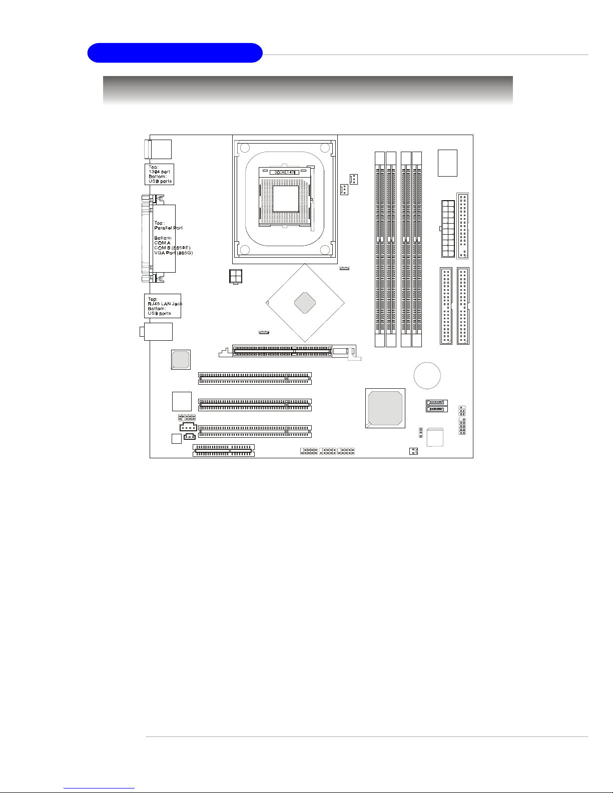
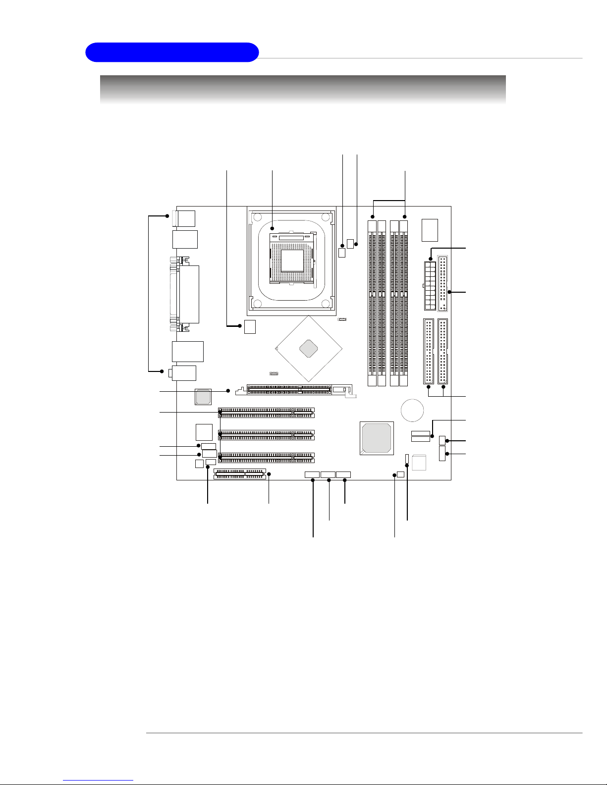
Mainboard Layout
MS-6743 v1.X M-ATX Mainboard
D
D
R
1
D
D
R
3
D
D
R
2
D
D
R
4
AGP Slot
T: mouse
B: keyboard
T:
Line-Out
B:Mic
Line-In
M:
JSPD1
CNR
JAUD1
JCD1
Codec
NEC
D72874GC
BATT
+
BIOS
W
i
n
b
o
n
d
8
3
6
2
7
H
F
-
A
W
ICH5
Intel
Springdale
865PE/G
I
D
E
1
I
D
E
2
F
D
D
1
PCI Slot 1
PCI Slot 2
PCI Slot 3
CPU_FAN
SYSTEM_FAN
JFP1
JIR1
JPW1
Intel
82562EZ
A
T
X
P
o
w
e
r
S
u
p
p
l
y
J1394_1
JBAT1
JCI1
JUSB1
SATA2
SATA1
JUSB2
Page 12
1-5
Getting Started
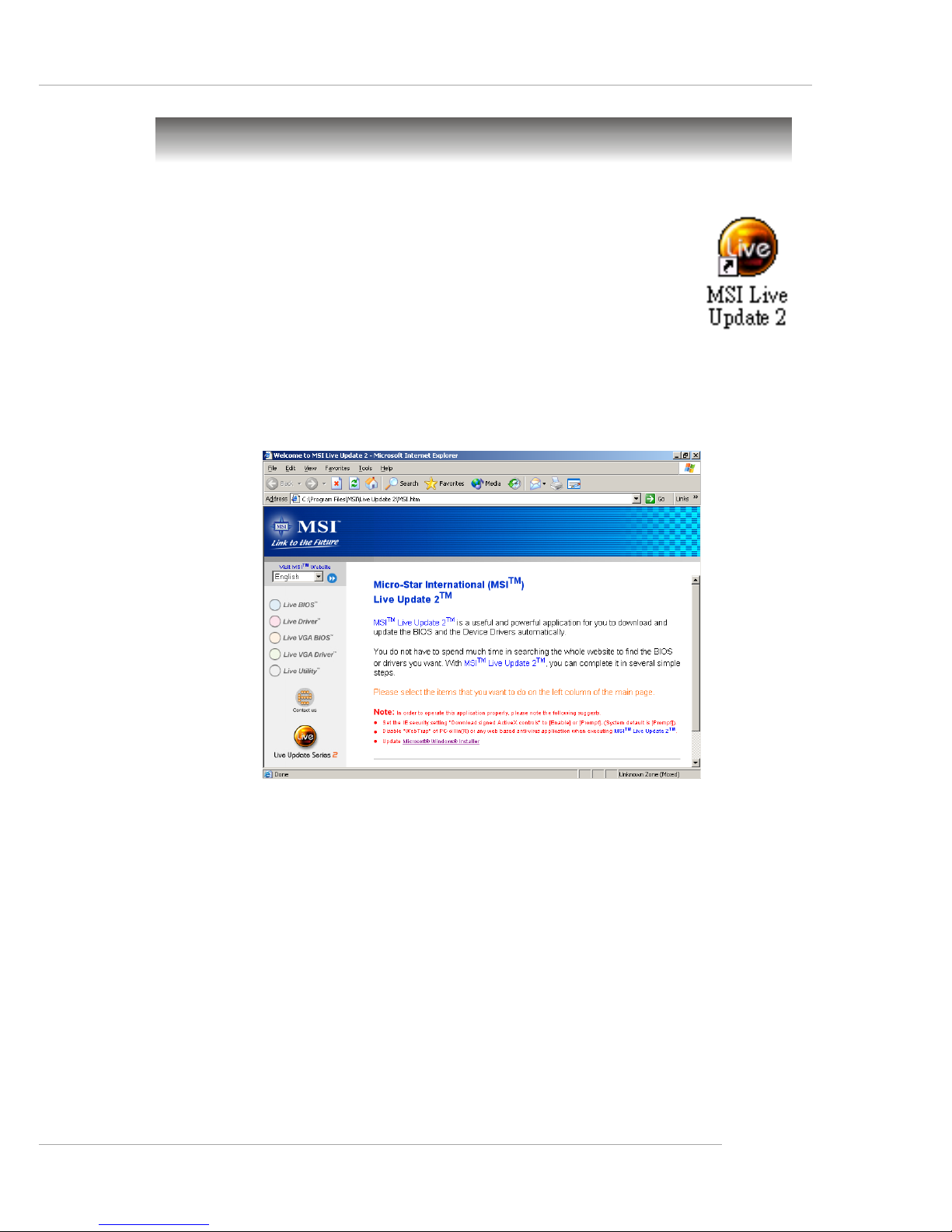
Live BIOS™/Live Driver™
The Live BIOS™/Live Driver™ is a tool used to detect and
update your BIOS/drivers online so that you don’t need to search
for the correct BIOS/driver version throughout the Web site. To
use the function, you need to install the “MSI Live Update 2”
application. After installation, the “MSI Live Update 2” icon (as
shown on the right) will appear on the screen.
Double click the “MSI Live Update 2” icon, and the following screen will appear:
Five buttons are placed on the leftmost pane of the screen. Click the desired
button to start the update process.
zz
zz
z Live BIOS – Updates the BIOS online.
zz
zz
z Live Driver – Updates the drivers online.
zz
zz
z Live VGA BIOS – Updates the VGA BIOS online.
zz
zz
z Live VGA Driver – Updates the VGA driver online.
zz
zz
z Live Utility – Updates the utilities online.
If the product you purchased does not support any of the functions listed
above, a “sorry” message is displayed. For more information on the update
instructions, insert the companion CD and refer to the “Live Update Guide”
under the “Manual” Tab.
MSI Special Features
Page 13
1-6
MS-6743 M-ATX Mainboard
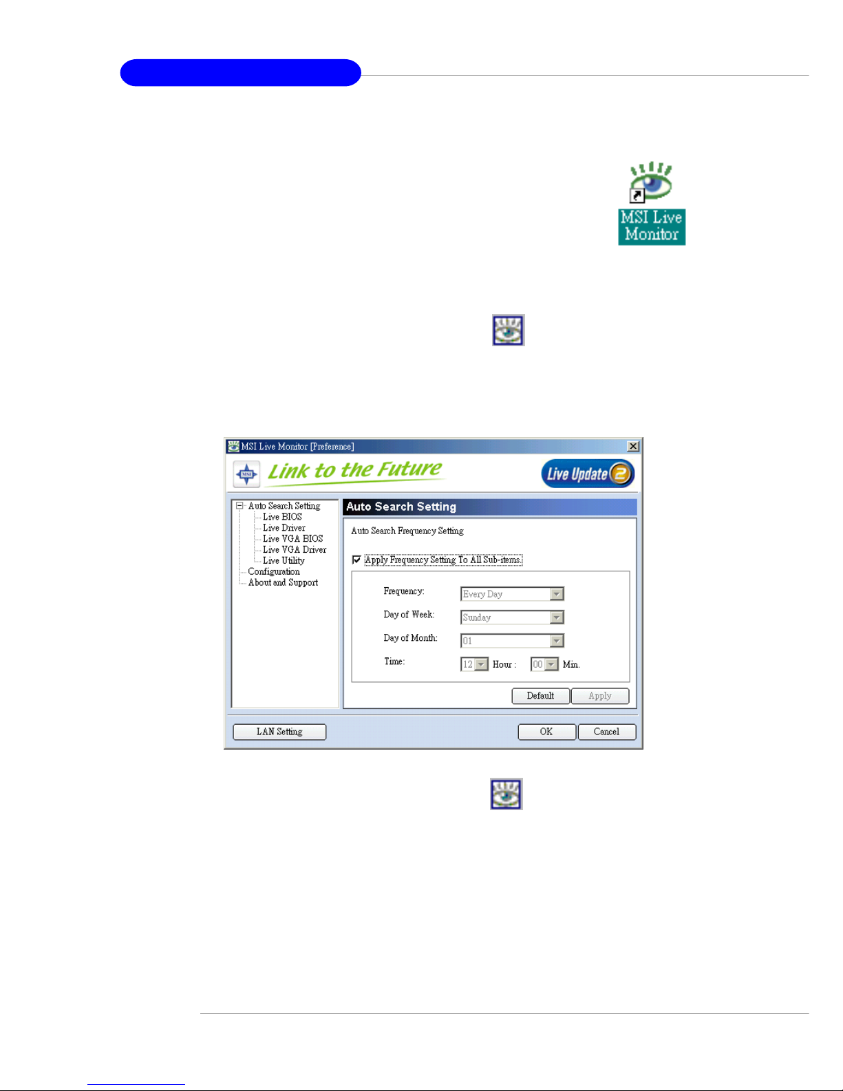
Live Monitor™
The Live Monitor™ is a tool used to schedule the search
for the latest BIOS/drivers version on the MSI Web site. To use
the function, you need to install the “MSI Live Update 2”
application. After installation, the “MSI Live Monitor” icon (as
shown on the right) will appear on the screen. Double click this
icon to run the application.
Double click the “MSI Live Monitor” icon at the lower-right corner
of the taskbar, and the following dialog box will appear. You can specify how
often the system will automatically search for the BIOS/drivers version, or
change the LAN settings right from the dialog box.
You can right-click the MSI Live Monitor icon to perform the functions
listed below:
zz
zz
z Auto Search – Searches for the BIOS/drivers version you need immediately.
zz
zz
z View Last Result – Allows you to view the last search result if there is any.
zz
zz
z Preference – Configures the Search function, including the Search schedule.
zz
zz
z Exit – Exits the Live Monitor™ application.
zz
zz
z FAQ – Provides a link to a database which contents various possible questions
about MSI's products for users to inquire.
Page 14
1-7
Getting Started
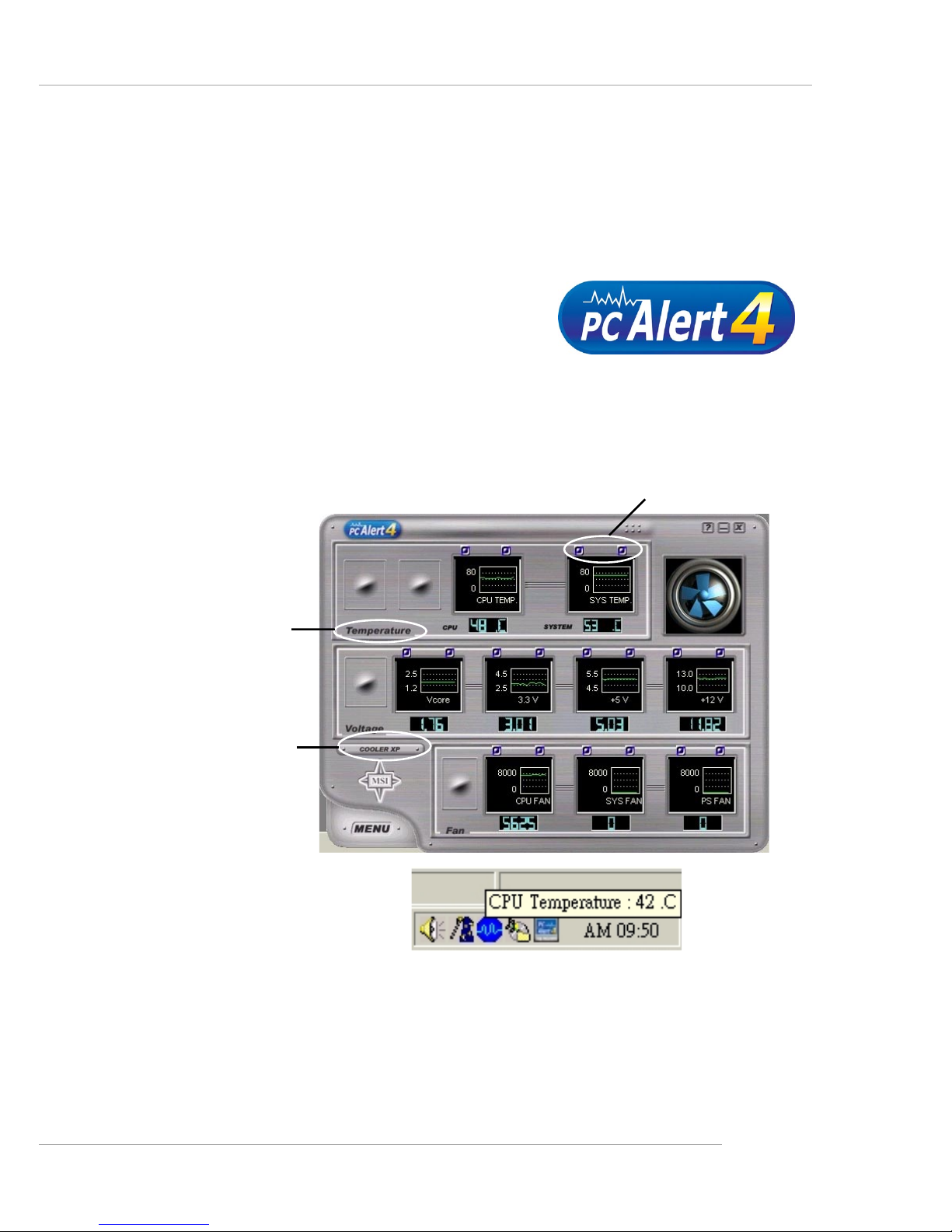
PC Alert™ 4
The PC AlertTM 4 is a utility you can find in the CD-ROM disk. The utility
is just like your PC doctor that can detect the following PC hardware status
during real time operation:
Ø monitor CPU & system temperatures
Ø monitor fan speeds
Ø monitor system voltages
If one of the items above is abnormal, the program main screen will be
immediately shown on the screen, with the abnormal item highlighted in red.
This will continue to be shown until the condition returns to the normal status.
Users can use the Adjusting Keys to change the minimum and maximum
threshold of each item for the system to send out a warning message. Click
Temperature to select the temperature modes of either Fahrenheit (oF) or Cel-
sius (oC). The PC Alert™ 4 icon on the Status Area will show the current CPU
temperature.
Temperature
Modes
Adjusting Keys
COOLER XP
Page 15
1-8
MS-6743 M-ATX Mainboard
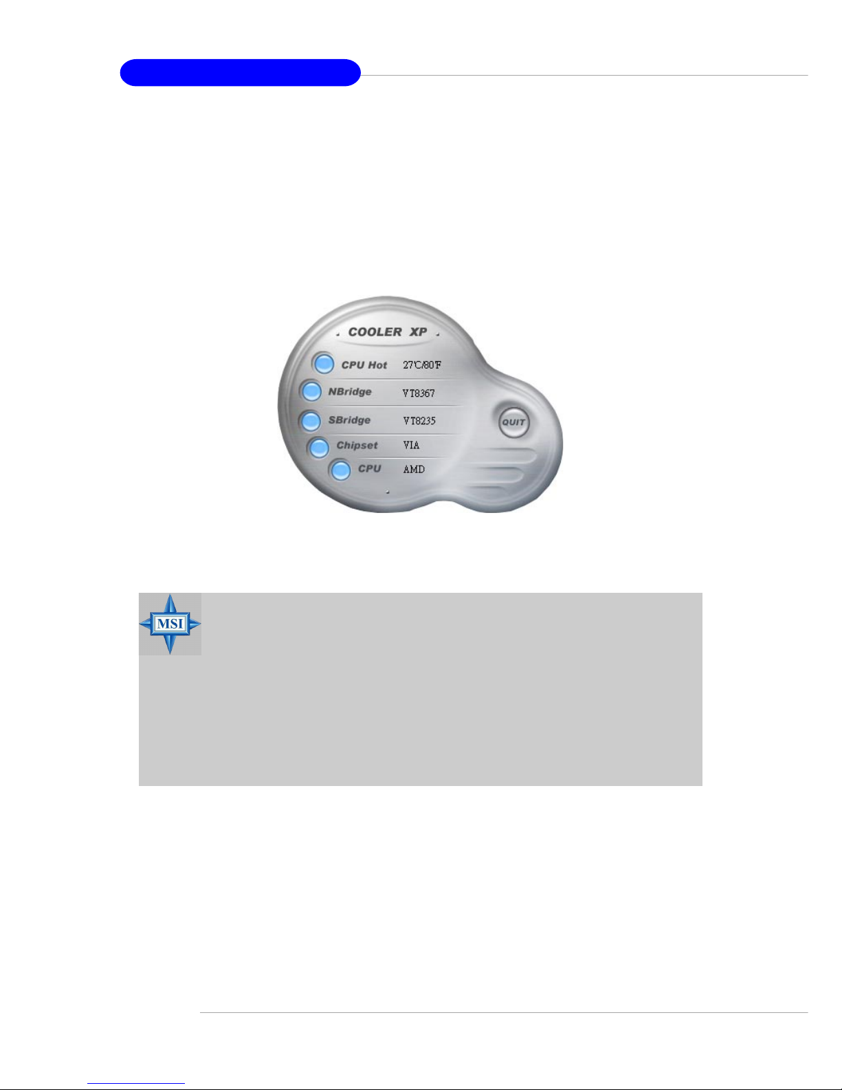
To better protect the CPU from overheating, a new feature, COOLER
XP, has been added to decrease the temperature of AMD Athlon™ XP CPU.
To do so, simply click COOLER XP and the screen will show the Cute skin (as
shown below) with information about the CPU and chipset. Right-click the
mouse to select the skin you want to switch to.
Cute
MSI Reminds You...
1. The new feature COOLER XP will work only if your mainboard
supports AMD Athlon™ XP CPU.
2. Items shown on PC Alert 4 vary depending on your system’s
status.
3. Whenever the minimum or maximum threshold of each item has
been changed, please close the PC Alert 4 program for the new
settings to take effect.
Page 16

2-1
Hardware Setup
Chapter 2. Hardware
Setup
This chapter tells you how to install the CPU, memory
modules, and expansion cards, as well as how to setup the jumpers on the mainboard. Also, it provides the instructions on connecting the peripheral devices, such as the mouse, keyboard,
etc.
While doing the installation, be careful in holding the components and follow the installation procedures.
Hardware Setup
Page 17
2-2
MS-6743 M-ATX Mainboard
Quick Components Guide
JCD1, p.2-19
JPW1, p.2-9 CPU, p.2-3
Back Panel
I/O, p.2-10
CPU_FAN1, p.2-18
FDD1, p.2-16
STAT2
SATA1, p.2-22
CNR1, p.2-29
JCI1, p.2-20
JSPD1, p.2-19
JFP1, p.2-21
JIR1, p.2-20
DDR DIMMs, p.2-7
ATX1, p.2-9
JAUD1, p.2-24
JUSB1, p.2-25
AGP slot, p.2-29
J1394_1, p.2-26
JBAT1, p.2-28
JUSB2, p.2-25
PCI slots, p.2-29
IDE1
IDE2, p.2-17
SYSTEM_FAN1, p.2-18
Page 18

2-3
Hardware Setup
Central Processing Unit: CPU
CPU Core Speed Derivation Procedure
CPU Clock multiplied by Core/Bus ratio equals the CPU core speed.
For example:
If CPU Clock = 100MHz
Core/Bus ratio = 14
then CPU core speed = Host Clock x Core/Bus ratio
= 100MHz x 14
= 1.4 GHz
The mainboard supports Intel® Pentium® 4/Celeron Northwood/Prescott
processor in the 478 pin package. The mainboard uses a CPU socket called
PGA478 for easy CPU installation. When you are installing the CPU, make
sure the CPU has a heat sink and a cooling fan attached on the top to
prevent overheating. If you do not find the heat sink and cooling fan, contact
your dealer to purchase and install them before turning on the computer.
Page 19
2-4
MS-6743 M-ATX Mainboard
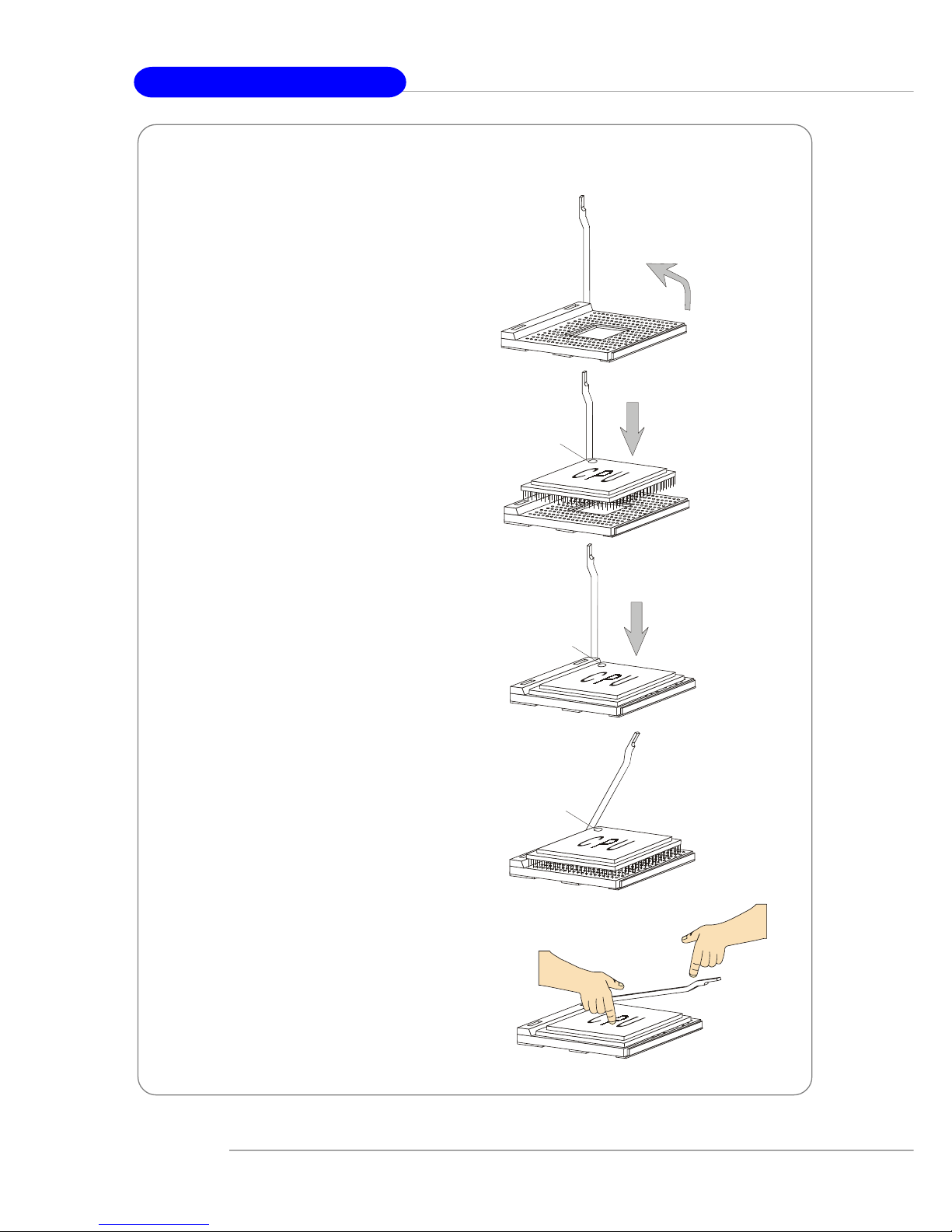
1. Please turn off the power and
unplug the power cord before
installing the CPU.
2. Pull the lever sideways away
from the socket. Make sure
to raise the lever up to a 90degree angle.
3. Look for the cut edge. The cut
edge should point towards the
lever pivot. The CPU can only
fit in the correct orientation.
4. If the CPU is correctly
installed, the pins should be
completely embedded into the
socket and can not be seen.
Please note that any violation
of the correct installation
procedures may cause
permanent damages to your
mainboard.
5. Press the CPU down firmly
into the socket and close the
lever. As the CPU is likely to
move while the lever is being
closed, always close the lever
with your fingers pressing
tightly on top of the CPU to
make sure the CPU is
properly and completely
embedded into the socket.
CPU Installation Procedures for Socket 478
Open Lever
Sliding
Plate
Dot / Cut edge
Close
Lever
Press down
the CPU
90 degree
Dot / Cut edge
Correct CPU placement
Dot / Cut edge
Incorrect CPU placement
X
O
Page 20
2-5
Hardware Setup
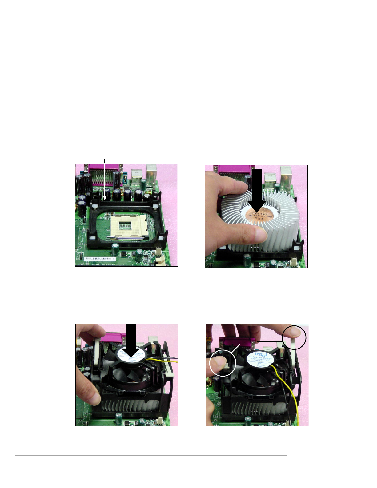
Installing the CPU Fan
As processor technology pushes to faster speeds and higher performance,
thermal management becomes increasingly important. To dissipate heat, you
need to attach the CPU cooling fan and heatsink on top of the CPU. Follow
the instructions below to install the Heatsink/Fan:
2. Position the heatsink onto the retention mechanism.
1. Locate the CPU and its retention
mechanism on the motherboard.
3. Mount the fan on top of the heatsink.
Press down the fan until its four clips
get wedged in the holes of the retention mechanism.
4. Press the two levers down to fasten
the fan. Each lever can be pressed
down in only ONE direction.
retention mechanism
levers
Page 21
2-6
MS-6743 M-ATX Mainboard
MSI Reminds You...
Overheating
Overheating will seriously damage the CPU and system, always make sure the cooling fan can work properly to protect
the CPU from overheating.
Replacing the CPU
While replacing the CPU, always turn off the ATX power supply or unplug the power supply’s power cord from grounded
outlet first to ensure the safety of CPU.
Overclocking
This motherboard is designed to support overclocking.
However, please make sure your components are able to tolerate such abnormal setting, while doing overclocking. Any attempt to operate beyond product specifications is not
recommended. We do not guarantee the damages or risks
caused by inadequate operation or beyond product
specifications.
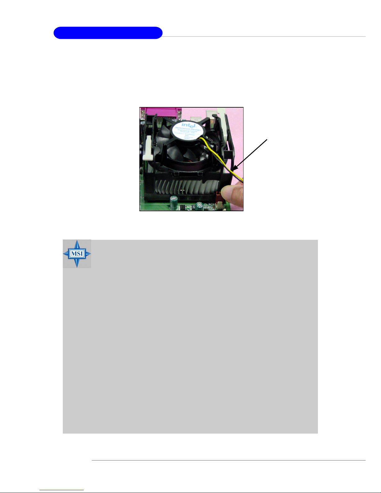
5. Connect the fan power cable from the mounted fan to the 3-pin fan power connector
on the board.
fan power cable
Page 22
2-7
Hardware Setup
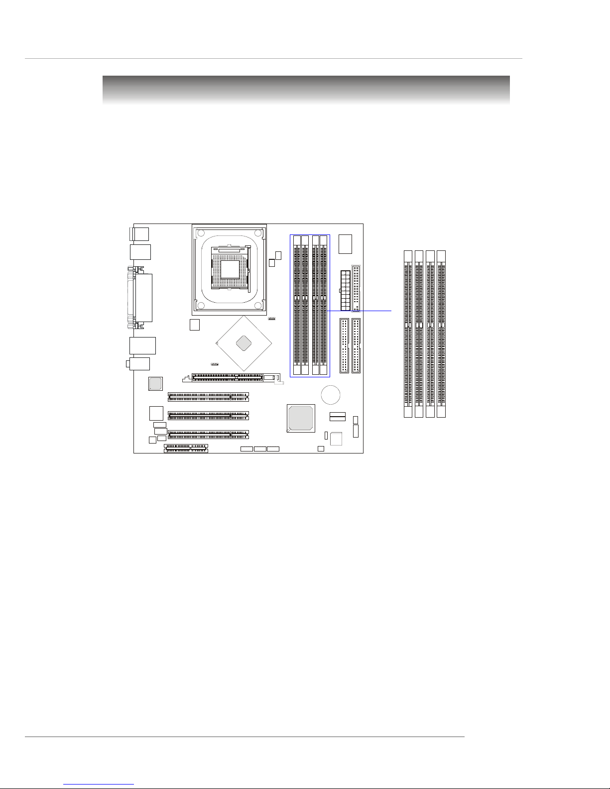
The mainboard provides 2 slots for 184-pin DDR SDRAM DIMM
(Double In-Line Memory Module) modules and supports the memory size up
to 2GB. You can install DDR400/DDR333/DDR266 modules on the DDR
DIMM slots (DDR 1~2).
Memory
Introduction to DDR SDRAM
DDR (Double Data Rate) SDRAM is similar to conventional SDRAM,
but doubles the rate by transferring data twice per cycle. It uses 2.5 volts as
opposed to 3.3 volts used in SDR SDRAM, and requires 184-pin DIMM modules rather than 168-pin DIMM modules used by SDR SDRAM. High memory
bandwidth makes DDR an ideal solution for high performance PC, workstations and servers.
D
I
M
M
1
D
I
M
M
2
D
I
M
M
3
D
I
M
M
4
Page 23
2-8
MS-6743 M-ATX Mainboard
DIMM Module Combination
Install at least one DIMM module on the slots. Memory modules can be
installed on the slots in any order. You can install either single- or doublesided modules to meet your own needs.
Memory modules can be installed in any combination as follows:
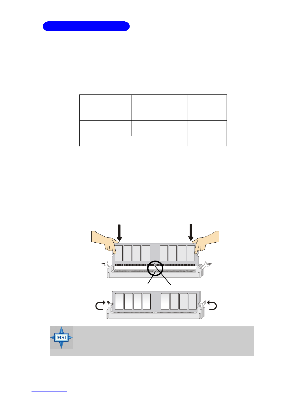
Installing DDR Modules
1. The DDR DIMM has only one notch on the center of module. The mod-
ule will only fit in the right orientation.
2. Insert the DIMM memory module vertically into the DIMM slot. Then
push it in until the golden finger on the memory module is deeply inserted in the socket.
3. The plastic clip at each side of the DIMM slot will automatically close.
S: Single Side D: Double Side
Slot Memory Module Total Memory
DIMM 1
(Bank 0 & 1)
S/D 64MB~1GB
DIMM 2
(Bank 2 & 3)
S/D 64MB~1GB
Maximum System Memory Supported
64MB~2GB
MSI Reminds You...
You can barely see the golden finger if the module is properly
inserted in the socket.
Volt
Notch
Page 24
2-9
Hardware Setup
Power Supply
The mainboard supports ATX power supply for the power system. Before inserting the power supply connector, always make sure that all components are installed properly to ensure that no damage will be caused.
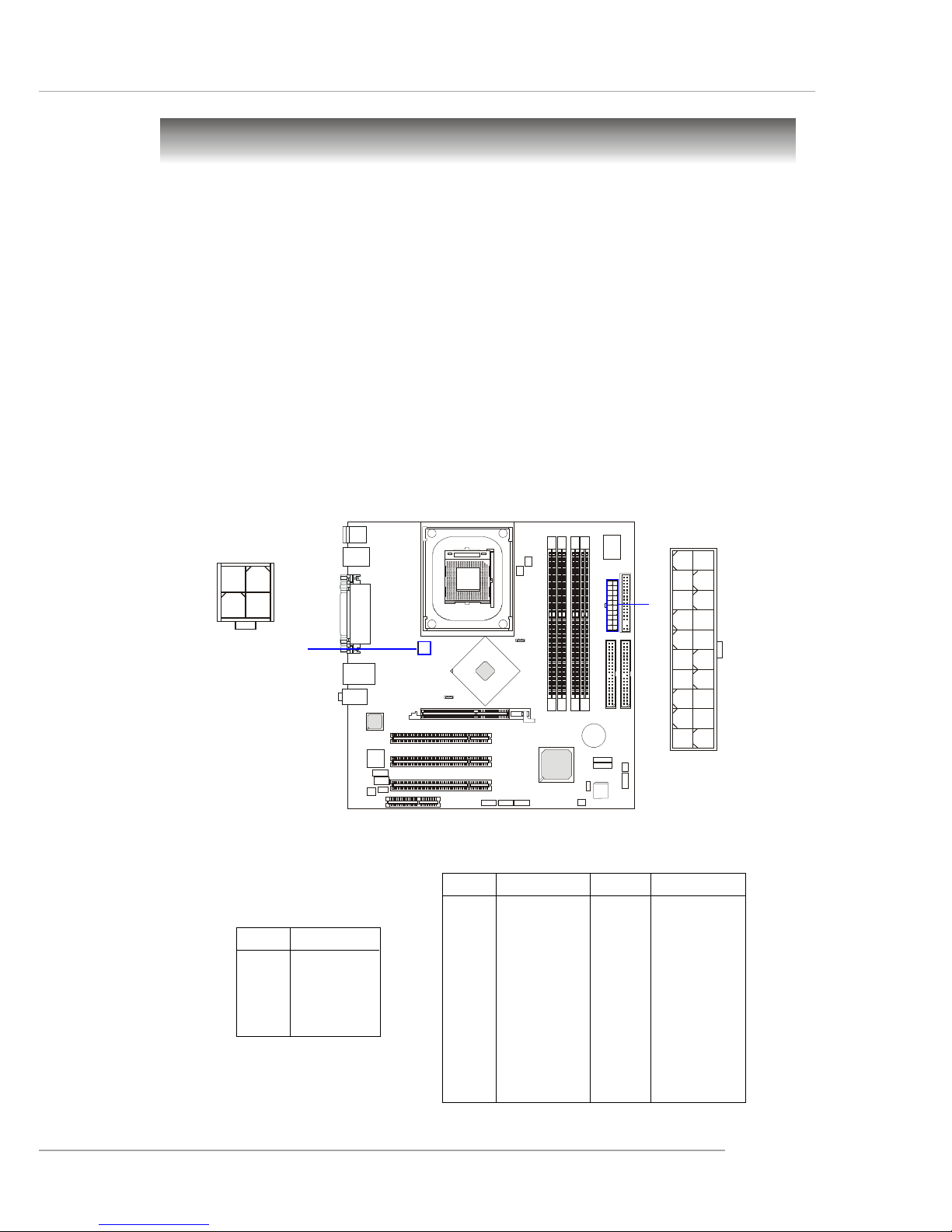
ATX 20-Pin Power Connector: ATX1
This connector allows you to connect to an ATX power supply. To
connect to the ATX power supply, make sure the plug of the power supply is
inserted in the proper orientation and the pins are aligned. Then push down
the power supply firmly into the connector.
ATX 12V Power Connector: JPW1
This 12V power connector is used to provide power to the CPU.
PIN SIGNAL
11 3.3V
12 -12V
13 GND
14 PS_ON
15 GND
16 GND
17 GND
18 -5V
19 5V
20 5V
PIN SIGNAL
1 3.3V
2 3.3V
3 GND
45V
5 GND
65V
7 GND
8 PW_OK
9 5V_SB
10 12V
ATX1 Pin Definition
PIN SIGNAL
1 GND
2 GND
3 12V
4 12V
JPW1 Pin Definition
JPW1
1
3
4
2
ATX1
10
1
20
11
Page 25
2-10
MS-6743 M-ATX Mainboard
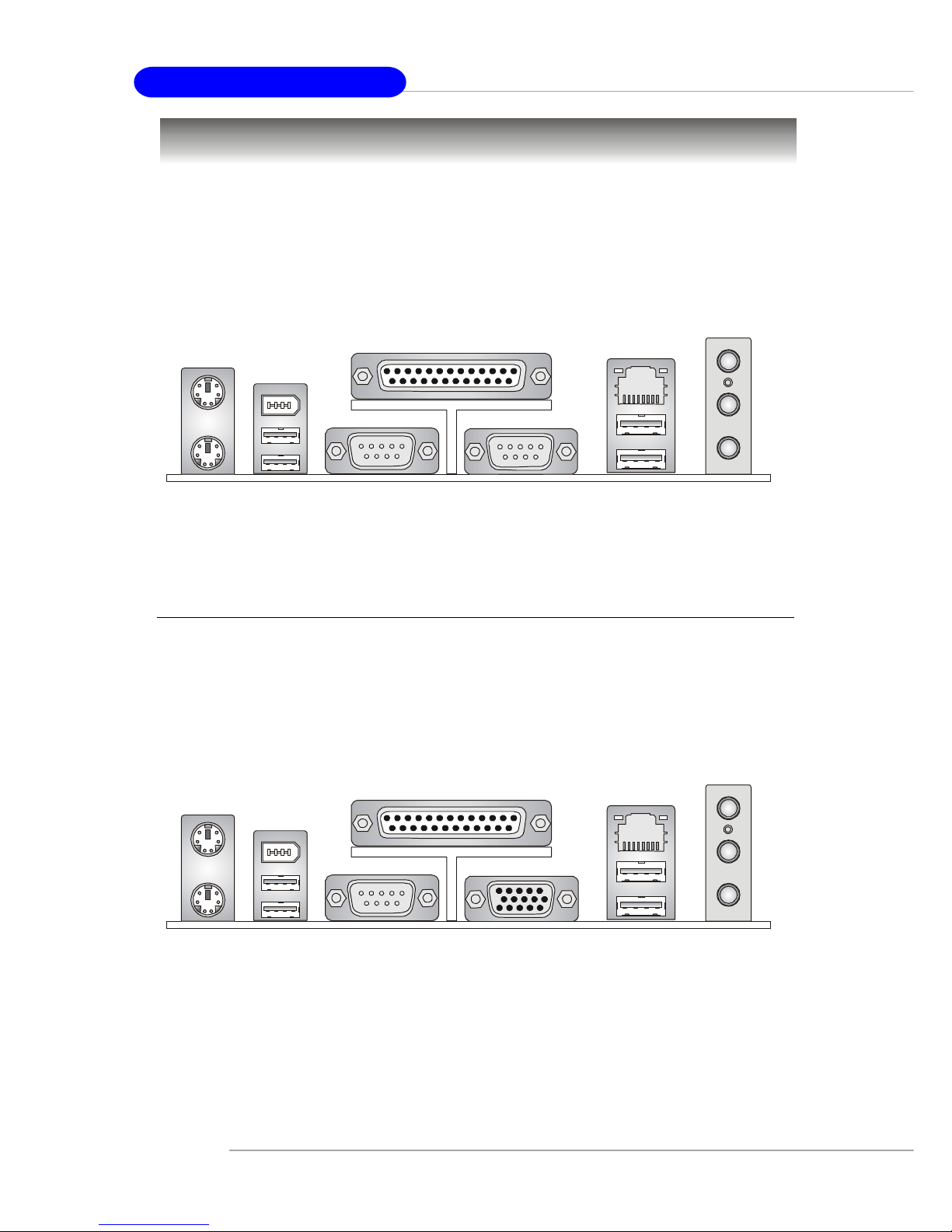
The back panel provides the following connectors:
Back Panel
For Springdale-PE
For Springdale-G
Mouse
Keyboard USB
Parallel
COM A
VGA
L-out
L-in
MIC
USB
LAN
Mouse
Keyboard USB
Parallel
COM A
COM B
L-out
L-in
USB
LAN
MIC
(Optional)
(Optional)
(Optional)
1394
(Optional)
1394
Page 26
2-11
Hardware Setup
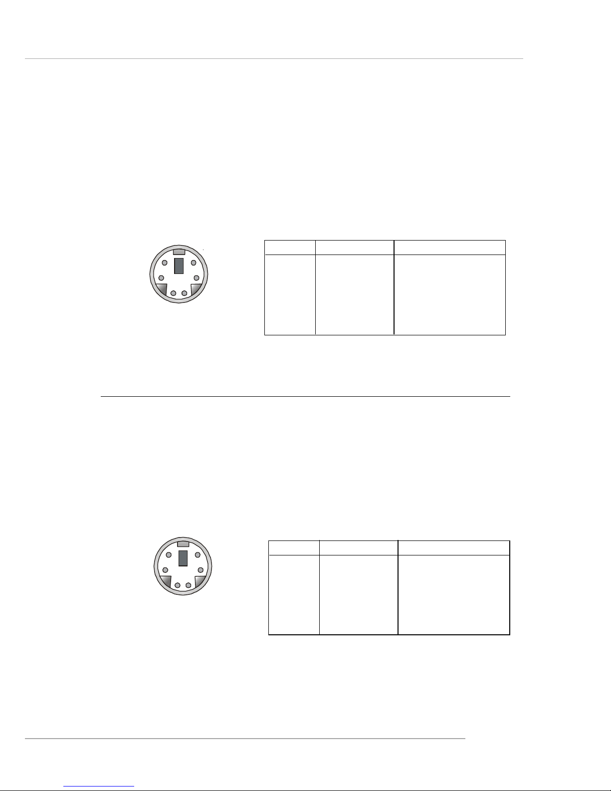
Keyboard Connector
The mainboard provides a standard PS/2® keyboard mini DIN connector for attaching a PS/2® keyboard. You can plug a PS/2® keyboard directly
into this connector.
PIN SIGNAL DESCRIPTION
1 Keyboard DATA Keyboard DATA
2 NC No connection
3 GND Ground
4 VCC +5V
5 Keyboard Clock Keyboard clock
6 NC No connection
Pin Definition
PS/2 Keyboard (6-pin Female)
2
1
3
4
5
6
Mouse Connector
The mainboard provides a standard PS/2® mouse mini DIN connector
for attaching a PS/2® mouse. You can plug a PS/2® mouse directly into this
connector. The connector location and pin assignments are as follows:
PIN SIGNAL DESCRIPTION
1 Mouse DATA Mouse DATA
2 NC No connection
3 GND Ground
4 VCC +5V
5 Mouse Clock Mouse clock
6 NC No connection
Pin Definition
PS/2 Mouse (6-pin Female)
2
1
3
4
5
6
Page 27

2-12
MS-6743 M-ATX Mainboard
USB Connectors
The mainboard provides a UHCI (Universal Host Controller Interface)
Universal Serial Bus root for attaching USB devices such as keyboard, mouse
or other USB-compatible devices. You can plug the USB device directly into
the connector.
PIN SIGNAL DESCRIPTION
1 VCC +5V
2 -Data 0 Negative Data Channel 0
3 +Data0 Positive Data Channel 0
4 GND Ground
5 VCC +5V
6 -Data 1 Negative Data Channel 1
7 +Data 1 Positive Data Channel 1
8 GND Ground
USB Port Description
USB Ports
1 2 3 4
5 6 7 8
RJ-45 LAN Jack (Optional)
The mainboard provides a RJ-45 connector that allows your computer
to be connected to a network environment.
LAN Jack
(RJ-45)
Activity
Indicators
Pin Signal Description
1 TDP Transmit differential pair
2 TDN Transmit differential pair
3 RDP Receive differential pair
4 NC Not used
5 NC Not used
6 RDN Receive differential pair
7 NC Not used
8 NC Not used
Page 28
2-13
Hardware Setup
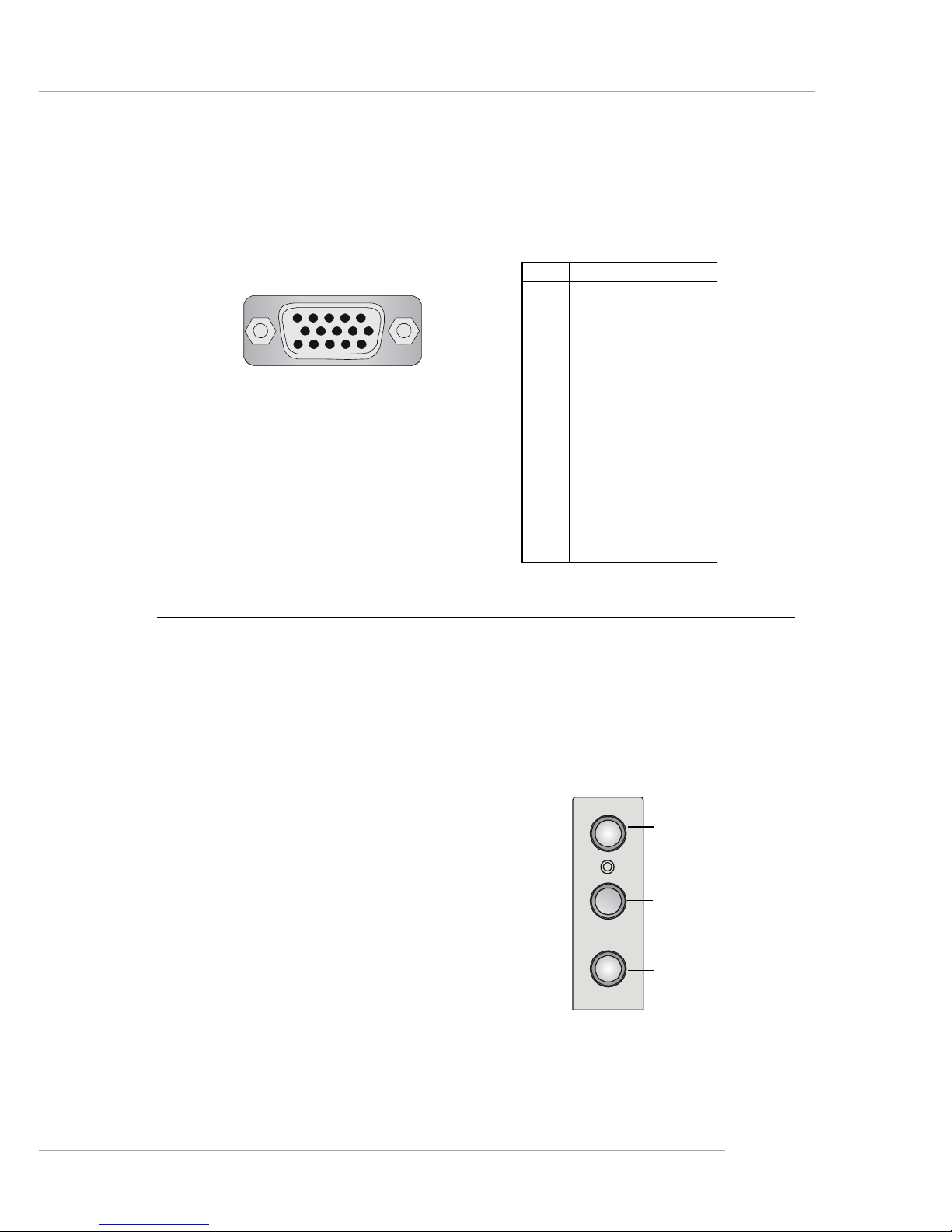
VGA Connector
The mainboard provides a DB 15-pin female connector to connect a
VGA monitor.
Pin Signal Description
1 RED
2 GREEN
3 BLUE
4 N/C
5 GND
6 GND
7 GND
8 GND
9 +5V
10 GND
11 N/C
12 SDA
13 Horizontal Sync
14 Vertical Sync
15 SCL
VGA Connector
(DB 15-pin)
1
5
11
15
Audio Port Connectors
Line Out is a connector for Speakers or Headphones. Line In is used
for external CD player, Tape player, or other audio devices. MIC-In is a
connector for microphones.
1/8” Stereo Audio Connectors
Line Out
Line In
MIC
Page 29
2-14
MS-6743 M-ATX Mainboard
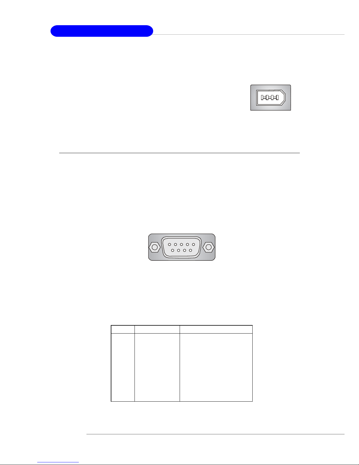
Serial Port Connectors: COM A/B
The mainboard offers two 9-pin male DIN connectors, COM A/B. Both
are 16550A high speed communication ports that send/receive 16 bytes FIFOs.
You can attach a serial mouse or other serial device directly to them.
PIN SIGNAL DESCRIPTION
1 DCD Data Carry Detect
2 SIN Serial In or Receive Data
3 SOUT Serial Out or Transmit Data
4 DTR Data Terminal Ready)
5 GND Ground
6 DSR Data Set Ready
7 RTS Request To Send
8 CTS Clear To Send
9 RI Ring Indicate
Pin Definition
9-Pin Male DIN Connector
COM A /B
1 2 3 4 5
6 7 8 9
IEEE1394 Port (Optional)
The mainboard provides one standard IEEE1394 port.
The standard IEEE1394 port connects to IEEE1394 devices
without external power. The IEEE1394 high-speed serial
bus complements USB by providing enhanced PC
connectivity for a wide range of devices, including
consumer electronics audio/video (A/V) appliances, storage
peripherals, other PCs, and portable devices.
Page 30
2-15
Hardware Setup
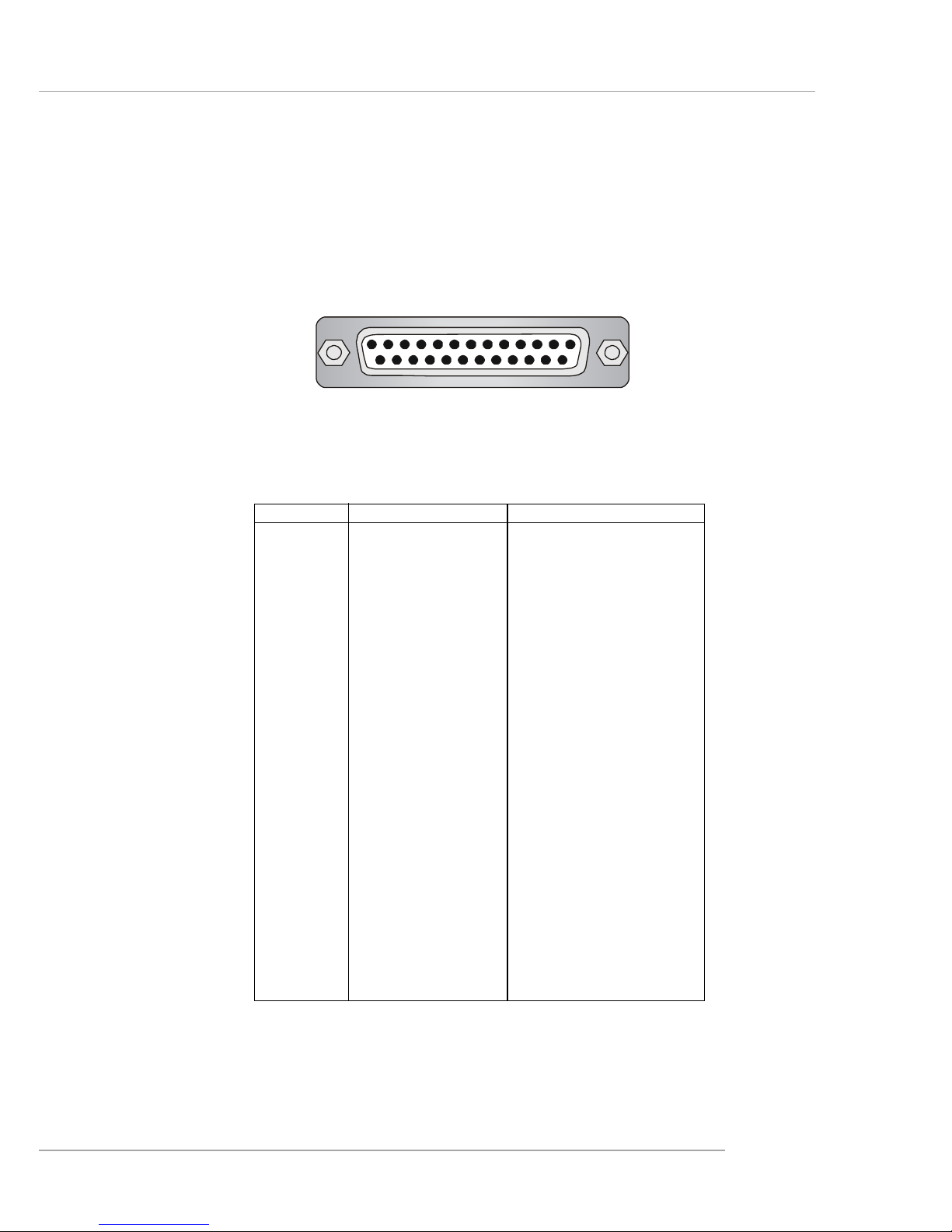
Parallel Port Connector: LPT1
The mainboard provides a 25-pin female centronic connector as LPT.
A parallel port is a standard printer port that supports Enhanced Parallel Port
(EPP) and Extended Capabilities Parallel Port (ECP) mode.
13 1
14
25
PIN SIGNAL DESCRIPTION
1 STROBE Strobe
2 DATA0 Data0
3 DATA1 Data1
4 DATA2 Data2
5 DATA3 Data3
6 DATA4 Data4
7 DATA5 Data5
8 DATA6 Data6
9 DATA7 Data7
10 ACK# Acknowledge
11 BUSY Busy
12 PE Paper End
13 SELECT Select
14 AUTO FEED# Automatic Feed
15 ERR# Error
16 INIT# Initialize Printer
17 SLIN# Select In
18 GND Ground
19 GND Ground
20 GND Ground
21 GND Ground
22 GND Ground
23 GND Ground
24 GND Ground
25 GND Ground
Pin Definition
Page 31

2-16
MS-6743 M-ATX Mainboard
The mainboard provides connectors to connect to FDD, IDE HDD, case,
modem, LAN, USB Ports, IR module and CPU/System/Power Supply FAN.
Floppy Disk Drive Connector: FDD1
The mainboard provides a standard floppy disk drive connector that
supports 360K, 720K, 1.2M, 1.44M and 2.88M floppy disk types.
Connectors
FDD1
Page 32

2-17
Hardware Setup
Hard Disk Connectors: IDE1 & IDE2
The mainboard has a 32-bit Enhanced PCI IDE and Ultra DMA 33/66/
100 controller that provides PIO mode 0~4, Bus Master, and Ultra DMA 33/
66/100 function. You can connect up to four hard disk drives, CD-ROM,
120MB Floppy (reserved for future BIOS) and other devices.
IDE1 (Primary IDE Connector)
The first hard drive should always be connected to IDE1. IDE1 can
connect a Master and a Slave drive. You must configure second hard
drive to Slave mode by setting the jumper accordingly.
IDE2 (Secondary IDE Connector)
IDE2 can also connect a Master and a Slave drive.
MSI Reminds You...
If you install two hard disks on cable, you must configure the
second drive to Slave mode by setting its jumper. Refer to the
hard disk documentation supplied by hard disk vendors for
jumper setting instructions.
IDE1IDE2
Page 33

2-18
MS-6743 M-ATX Mainboard
Fan Power Connectors: CPU_FAN/SYSTEM_FAN
The CPU_FAN (processor fan), SYSTEM_FAN1 (system fan) support
system cooling fan with +12V. It supports three-pin head connector. When
connecting the wire to the connectors, always take note that the red wire is the
positive and should be connected to the +12V, the black wire is Ground and
should be connected to GND. If the mainboard has a System Hardware Monitor chipset on-board, you must use a specially designed fan with speed sensor
to take advantage of the CPU fan control.
MSI Reminds You...
Always consult the vendors for proper CPU cooling fan.
SYSTEM_FAN
SENSOR
+12V
GND
CPU_FAN
SENSOR
+12V
GND
Page 34

2-19
Hardware Setup
CD-In Connector: JCD1
The connector is for CD-ROM audio connector.
SPDIF-Out Connector: JSPD1 (Optional)
This connector is used to connect SPDIF (Sony & Philips Digital Interconnect Format) interface for digital audio transmission.
JCD1
14
JSPD1
VCC
SPDIF
GND
Connected to JSPD1
SPDIF Bracket (Optional)
Page 35

2-20
MS-6743 M-ATX Mainboard
Chassis Intrusion Switch Connector: JCI1
This connector is connected to a 2-pin chassis switch. If the chassis is opened,
the switch will be short connected. The system will record this status and
show a warning message on the screen. To clear the warning, you must enter
the BIOS utility and clear the record. JCI1 is compliant with Intel® Front
Panel I/O Connectivity Design Guide.
IrDA Infrared Module Header: JIR1 (865PE only)
The connector allows you to connect to IrDA Infrared module. You
must configure the setting through the BIOS setup to use the IR function.
JIR1 is compliant with Intel® Front Panel I/O Connectivity Design Guide.
Pin Signal
1NC
2NC
3 VCC5
4 GND
5 IRTX
6 IRRX
Pin Definition
2
56
JIR1
1
JCI1
GND
CINTRU
1
2
Page 36

2-21
Hardware Setup
Front Panel Connector: JFP1
The mainboard provides two front panel connectors for electrical
connection to the front panel switches and LEDs. JFP1 is compliant with Intel
®
Front Panel I/O Connectivity Design Guide.
PIN SIGNAL DESCRIPTION
1 HD_LED_P Hard disk LED pull-up
2 FP PWR/SLP MSG LED pull-up
3 HD_LED_N Hard disk active LED
4 FP PWR/SLP MSG LED pull-up
5 RST_SW_N Reset Switch low reference pull-down to GND
6 PWR_SW_P Power Switch high reference pull-up
7 RST_SW_P Reset Switch high reference pull-up
8 PWR_SW_N Power Switch low reference pull-down to GND
9 RSVD_DNU Reserved. Do not use.
JFP1 Pin Definition
JFP1
1
910
2
Reset
Switch
Power
LED
Power
Switch
HDD
LED
Page 37

2-22
MS-6743 M-ATX Mainboard
Serial ATA Connectors: SATA1 / SATA2
The mainboard has dual high-speed Serial ATA interface connectors,
SATA1 & SATA2. Each supports 1st generation serial ATA data rates of 150
MB/s. Both connectors are fully compliant with Serial ATA 1.0 specifications.
Each Serial ATA connector can connect to 1 hard disk device. Please refer to
Serial ATA Raid manual for detail software installation procedure.
PIN SIGNAL PIN SIGNAL
1 GND 2 TXP
3 TXN 4 GND
5 RXN 6 RXP
7 GND
SATA1 & SATA2 Pin Definition
SATA1
SATA2
Page 38

2-23
Hardware Setup
MSI Reminds You...
Please do not fold the serial ATA cable in a 90-degree angle,
which will cause the loss of data during the transmission.
Connect to SATA1 or SATA2
Take out the dust cover and
connect to the hard disk
devices
Optional Serial ATA cable
Page 39

2-24
MS-6743 M-ATX Mainboard
Front Panel Audio Connector: JAUD1
The JAUD1 front panel audio connector allows you to connect to the
front panel audio and is compliant with Intel® Front Panel I/O Connectivity
Design Guide.
MSI Reminds You...
If you don’t want to connect to the front audio
header, pins 5 & 6, 9 & 10 have to be jumpered in
order to have signal output directed to the rear
audio ports. Otherwise, the Line-Out connector on
the back panel will not function.
5
6
10
9
PIN SIGNAL DESCRIPTION
1 AUD_MIC Front panel microphone input signal
2 AUD_GND Ground used by analog audio circuits
3 AUD_MIC_BIAS Microphone power
4 AUD_VCC Filtered +5V used by analog audio circuits
5 AUD_FPOUT_R Right channel audio signal to front panel
6 AUD_RET_R Right channel audio signal return from front panel
7 HP_ON Reserved for future use to control headphone amplifier
8 KEY No pin
9 AUD_FPOUT_L Left channel audio signal to front panel
10 AUD_RET_L Left channel audio signal return from front panel
JAUD1 Pin Definition
JAUD1
1
2
9
10
Page 40

2-25
Hardware Setup
Front USB Connectors: JUSB1 / JUSB2
The mainboard provides one USB 2.0 pin header JUSB1 that is compliant with Intel® I/O Connectivity Design Guide. USB 2.0 technology increases
data transfer rate up to a maximum throughput of 480Mbps, which is 40
times faster than USB 1.1, and is ideal for connecting high-speed USB interface peripherals such as USB HDD, digital cameras, MP3 players, printers,
modems and the like.
PIN SIGNAL PIN SIGNAL
1 VCC 2 VCC
3 USB0- 4 USB1-
5 USB0+ 6 USB1+
7 GND 8 GND
9 Key 10 USBOC
JUSB1/2 Pin Definition
JUSB1
(USB 2.0/Intel spec)
1
9
2 10
JUSB2
(USB 2.0/Intel spec)
1
9
2 10
Page 41

2-26
MS-6743 M-ATX Mainboard
IEEE 1394 Connector: J1394_1
The mainboard provides three 1394 pin headers that allow you to con-
nect optional IEEE 1394 ports.
J1394_1
J1394_1 Pin Definition
PIN SIGNAL PIN SIGNAL
1 TPA+ 2 TPA-
3 Ground 4 Ground
5 TPB+ 6 TPB-
7 Cable power 8 Cable power
9 Key (no pin) 10 Ground
9
2
10
1
Page 42

2-27
Hardware Setup
How to attach the IEEE 1394 Port:
Foolproof
design
Connected separately to J1394_1,
J1394_2 and J1394_3.
1394 Port
Page 43

2-28
MS-6743 M-ATX Mainboard
The motherboard provides the following jumpers for you to set the
computer’s function. This section will explain how to change your
motherboard’s function through the use of jumpers.
Jumpers
MSI Reminds You...
You can clear CMOS by shorting 2-3 pin while the system is off.
Then return to 1-2 pin position. Avoid clearing the CMOS while
the system is on; it will damage the mainboard.
Clear CMOS Jumper: JBAT1
There is a CMOS RAM on board that has a power supply from external
battery to keep the data of system configuration. With the CMOS RAM, the
system can automatically boot OS every time it is turned on. That battery has
long life time for at least 5 years. If you want to clear the system configuration,
use the JBAT1 (Clear CMOS Jumper ) to clear data. Follow the instructions
below to clear the data:
JBAT1
1
3
Clear DataKeep Data
1
3
1
3
Page 44

2-29
Hardware Setup
Slots
AGP (Accelerated Graphics Port) Slot
The AGP slot allows you to insert the AGP graphics card. AGP is an
interface specification designed for the throughput demands of 3D graphics.
It introduces a 66MHz, 32-bit channel for the graphics controller to directly
access main memory. The mainboard supports one AGP 8x slot.
PCI (Peripheral Component Interconnect) Slots
The PCI slots allow you to insert the expansion cards to meet your needs.
When adding or removing expansion cards, make sure that you unplug the
power supply first. Meanwhile, read the documentation for the expansion card
to make any necessary hardware or software settings for the expansion card,
such as jumpers, switches or BIOS configuration.
CNR (Communication Network Riser) Slot
The CNR slot allows you to insert the CNR expansion cards. CNR is
specifically designed for audio or modem riser cards for ATX family
motherboards. Its main processing is done through software and controlled
by the motherboard’s chipset.
The motherboard provides one AGP slot and three 32-bit PCI bus slots.
PCI Slots
AGP Slot
CNR Slot
Page 45

2-30
MS-6743 M-ATX Mainboard
PCI Interrupt Request Routing
The IRQ, abbreviation of interrupt request line and pronounced I-R-Q,
are hardware lines over which devices can send interrupt signals to the
microprocessor. The PCI IRQ pins are typically connected to the PCI bus INT
A# ~ INT D# pins as follows:
Order 1 Order 2 Order 3 Order 4
PCI Slot 1 INT G# INT H# INT E# INT F#
PCI Slot 2 INT F# INT B# INT H# INT E#
PCI Slot 3 INT E# INT E# INT G# INT H#
Page 46

3-1
BIOS Setup
Chapter 3. BIOS Setup
This chapter provides information on the BIOS Setup program
and allows you to configure the system for optimum use.
You may need to run the Setup program when:
An error message appears on the screen during the system
booting up, and requests you to run SETUP.
You want to change the default settings for customized
features.
BIOS Setup
Page 47

3-2
MS-6743 M-ATX Mainboard
Entering Setup
Power on the computer and the system will start POST (Power On Self Test)
process. When the message below appears on the screen, press <DEL> key to
enter Setup.
Press DEL to enter SETUP
If the message disappears before you respond and you still wish to enter Setup,
restart the system by turning it OFF and On or pressing the RESET button.
You may also restart the system by simultaneously pressing <Ctrl>, <Alt>,
and <Delete> keys.
Control Keys
<↑>
Move to the previous item
<↓>
Move to the next item
<←>
Move to the it em in the left hand
<→>
Move to the it em in the right hand
<Enter> Select the item
<Esc> Jumps to the Exit menu or returns to the main menu from a s ubmenu
<+/PU > Incr ease the numer i c value or make c han ge s
<-/PD> Decrease the numeric value or make changes
<F1> General help, only for Status Page Setup Menu and Option Page
Setup Menu
<F5> Re st ore the previous CMOS value from CMOS, only for Option Page
Setup Menu
<F6> Load the default CMOS value from Fail-Safe default table, only for
Option Page Setup Menu
<F7> Load Optimized defaults
<F10> Save all the CMOS changes and exit
Page 48

3-3
BIOS Setup
Getting Help
After entering the Setup menu, the first menu you will see is the Main Menu.
Main Menu
The main menu lists the setup functions you can make changes to. You can
use the control keys ( ↑↓ ) to select the item. The on-line description of the
highlighted setup function is displayed at the bottom of the screen.
Sub-Menu
If you find a right pointer symbol (as shown
in the right view) appears to the left of certain fields that means a sub-menu containing
additional options can be launched from this
field. You can use control keys ( ↑↓ ) to
highlight the field and press <Enter> to call
up the sub-menu. Then you can use the control keys to enter values and move from field
to field within a sub-menu. If you want to
return to the main menu, just press <Esc >.
General Help <F1>
The BIOS setup program provides a General Help screen. You can call up
this screen from any menu by simply pressing <F1>. The Help screen lists the
appropriate keys to use and the possible selections for the highlighted item.
Press <Esc> to exit the Help screen.
MSI Reminds You...
The items under each BIOS category described in this chapter
are under continuous update for better system performance.
Therefore, the description may be slightly different from the latest
BIOS and should be held for reference only.
Page 49

3-4
MS-6743 M-ATX Mainboard
The Main Menu
Standard CMOS Features
Use this menu for basic system configurations, such as time, date etc.
Advanced BIOS Features
Use this menu to setup the items of special enhanced features.
Advanced Chipset Features
Use this menu to change the values in the chipset registers and optimize your
system’s performance.
Integrated Peripherals
Use this menu to specify your settings for integrated peripherals.
Power Management Setup
Use this menu to specify your settings for power management.
PnP/PCI Configurations
This entry appears if your system supports PnP/PCI.
Once you enter Phoenix-Award® BIOS CMOS Setup Utility, the Main Menu
(Figure 1) will appear on the screen. The Main Menu allows you to select
from twelve setup functions and two exit choices. Use arrow keys to select
among the items and press <Enter> to accept or enter the sub-menu.
Page 50

3-5
BIOS Setup
PC Health Status
This entry shows your PC health status.
Frequency/Voltage Control
Use this menu to specify your settings for frequency/voltage control.
Load High Performance Defaults
Use this menu to load the BIOS values for the best system performance, but
the system stability may be affected.
Load BIOS Setup Defaults
Use this menu to load factory default settings into the BIOS for stable system
performance operations.
Set Supervisor Password
Use this menu to set Supervisor Password.
Set User Password
Use this menu to set User Password.
Save & Exit Setup
Save changes to CMOS and exit setup.
Exit Without Saving
Abandon all changes and exit setup.
Page 51

3-6
MS-6743 M-ATX Mainboard
Standard CMOS Features
Date
This allows you to set the system to the date that you want (usually the current
date). The format is <day><month> <date> <year>.
day Day of the week, from Sun to Sat, determined by
BIOS. Read-only.
month The month from Jan. through Dec.
date The date from 1 to 31 can be keyed by numeric
function keys.
year The year can be adjusted by users.
Time
This allows you to set the system time that you want (usually the current
time). The time format is <hour> <minute> <second>.
The items in Standard CMOS Features Menu are divided into 11 categories.
Each category includes no, one or more than one setup items. Use the arrow
keys to highlight the item and then use the <PgUp> or <PgDn> keys to select
the value you want in each item.
Page 52

3-7
BIOS Setup
IDE Channel 0/1 Master/Slave
IDE Channel 2/3 Master
Press PgUp/<+> or PgDn/<-> to select Manual, None or Auto type. Note
that the specifications of your drive must match with the drive table. The
hard disk will not work properly if you enter improper information for this
category. If your hard disk drive type is not matched or listed, you can use
Manual to define your own drive type manually.
If you select Manual, related information is asked to be entered to the following items. Enter the information directly from the keyboard. This information should be provided in the documentation from your hard disk vendor or
the system manufacturer.
Access Mode The settings are CHS, LBA, Large, Auto.
Capacity The formatted size of the storage device.
Cylinder Number of cylinders.
Head Number of heads.
Precomp Write precompensation.
Landing Zone Cylinder location of the landing zone.
Sector Number of sectors.
MSI Reminds You...
IDE Channel 2/3 Master only available when the following
two conditions come into existence at the same time:
hh
hh
h BIOS version after 2.0
hh
hh
h On-Chip Serial ATA is set to Auto (please refer Integrated
Peripherals/OnChip IDE Device/On-Chip Serial ATA for
details.)
When BIOS version 1.0 is installed, IDE Channel 0/1 Master/
Slave support maximum 4 IDE devices, including two Serial
ATA devices. In different words, if two Serial ATA devices is
installed, there will be only two IDE Channel left to support
two IDE devices.
Page 53

3-8
MS-6743 M-ATX Mainboard
Drive A:/B:
This item allows you to set the type of floppy drives installed. Available
options: None, 360K, 5.25 in., 1.2M, 5.25 in., 720K, 3.5 in., 1.44M, 3.5 in.,
2.88M, 3.5 in..
Video
The setting controls the type of video adapter used for the primary monitor of
the system. Available options: EGA/VGA , CGA 40, CGA 80, MONO.
Halt On
The setting determines whether the system will stop if an error is detected at
boot. Available options are:
All Errors The system stops when any error is detected.
No Errors The system doesn’t stop for any detected error.
All, But Keyboard The system doesn’t stop for a keyboard error.
All, But Diskette The system doesn’t stop for a disk error.
All, But Disk/Key The system doesn’t stop for either a disk or a
keyboard error.
CPU Type/BIOS Version/System Memory/Total Memory/
Video Memory (865G only)
These items show the CPU type, BIOS version and memory status of your
system (read only).
Page 54

3-9
BIOS Setup
Advanced BIOS Features
BIOS Virus Warning
The item is to set the Virus Warning feature for IDE Hard Disk boot sector
protection. If the function is enabled and any attempt to write data into this
area is made, BIOS will display a warning message on screen and beep.
Settings: Disabled and Enabled.
Hyper-Threading Technology
The processor uses Hyper-Threading technology to increase transaction
rates and reduces end-user response times. The technology treats the two
cores inside the processor as two logical processors that can execute
instructions simultaneously. In this way, the system performance is highly
improved. If you disable the function, the processor will use only one core
to execute the instructions. Settings: Enabled, Disabled.
Quick Boot
Setting the item to Enabled allows the system to boot within 5 seconds since
it will skip some check items Settings: Disabled, Enabled.
Full Screen LOGO Show
This item enables you to show the company logo on the bootup screen. Settings are:
Enabled Shows a still image (logo) on the full screen at boot.
Disabled Shows the POST messages at boot.
Page 55

3-10
MS-6743 M-ATX Mainboard
1st/2nd/3rd Boot Device
The items allow you to set the sequence of boot devices where BIOS attempts
to load the disk operating system. The settings are:
Floppy The system will boot from floppy drive.
LS120 The system will boot from LS-120 drive.
HDD-0 The system will boot from the first HDD.
SCSI The system will boot from the SCSI.
CDROM The system will boot from the CD-ROM.
HDD-1 The system will boot from the second HDD.
HDD-2 The system will boot from the third HDD.
HDD-3 The system will boot from the fourth HDD.
ZIP100 The system will boot from ATAPI ZIP drive.
USB-FDD The system will boot from USB-interfaced floppy drive.
USB-ZIP The system will boot from any USB-interfaced ATAPI
ZIP drive
USB-CDROM The system will boot from the USB-interfaced CD-ROM.
USB-HDD The system will boot from the USB-interfaced HDD.
LAN The system will boot from the Network drive.
Disabled Disable this sequence.
MSI Reminds You...
Available settings for “1st/2nd/3rd Boot Device” vary depending on the bootable devices you have installed. For example, if
you did not install a floppy drive, the setting “Floppy” does not
show up.
MSI Reminds You...
Enabling the functionality of Hyper-Threading Technology for
your computer system requires ALL of the following platform
Components:
*CPU: An Intel® Pentium® 4 Processor with HT Technology;
*Chipset: An Intel® Chipset that supports HT Technology;
*BIOS: A BIOS that supports HT Technology and has it enabled;
and
*OS: An operating system that supports HT Technology.
For more information on Hyper-threading Technology, go to:
www.intel.com/info/hyperthreading
Page 56

3-11
BIOS Setup
Boot Other Device
Setting the option to Enabled allows the system to try to boot from other
device if the system fails to boot from the 1st/2nd/3rd boot device.
Swap Floppy Drive
Setting to Enabled will swap floppy drives A: and B:.
Boot Up NumLock LED
This setting is to set the Num Lock status when the system is powered on.
Setting to On will turn on the Num Lock key when the system is powered on.
Setting to Off will allow users to use the arrow keys on the numeric keypad.
Setting options: On, Off.
Gate A20 Option
This item is to set the Gate A20 status. A20 refers to the first 64KB of extended memory. When the default value Fast is selected, the Gate A20 is
controlled by Port92 or chipset specific method resulting in faster system
performance. When Normal is selected, A20 is controlled by a keyboard controller or chipset hardware.
Typematic Rate Setting
This item is used to enable or disable the typematic rate setting including
Typematic Rate & Typematic Delay.
Typematic Rate (Chars/Sec)
After Typematic Rate Setting is enabled, this item allows you to set the rate
(characters/second) at which the keys are accelerated. Settings: 6, 8, 10, 12,
15, 20, 24 and 30.
Typematic Delay (Msec)
This item allows you to select the delay between when the key was first pressed
and when the acceleration begins. Settings: 250, 500, 750 and 1000.
Security Option
This specifies the type of BIOS password protection that is implemented. Settings are described below:
Page 57

3-12
MS-6743 M-ATX Mainboard
Option Description
Setup The password prompt appears only when end users try to
run Setup.
System A password prompt appears every time when the com-
puter is powered on or when end users try to run Setup.
APIC Function
This field is used to enable or disable the APIC (Advanced Programmable
Interrupt Controller). Due to compliance with PC2001 design guide, the system
is able to run in APIC mode. Enabling APIC mode will expand available IRQ
resources for the system. Settings: Enabled and Disabled.
MPS Table Version
This field allows you to select which MPS (Multi-Processor Specification)
version to be used for the operating system. You need to select the MPS version supported by your operating system. To find out which version to use,
consult the vendor of your operating system. Settings: 1.4, 1.1.
Boot OS/2 Select For DRAM > 64MB
This allows you to run the OS/2® operating system with DRAM greater than
64MB. Setting options: Non-OS2, OS2.
Hard Disk S.M.A.R.T.
This allows you to activate the S.M.A.R.T. (Self-Monitoring Analysis & Reporting Technology) capability for the hard disks. S.M.A.R.T is a utility that
monitors your disk status to predict hard disk failure. This gives you an opportunity to move data from a hard disk that is going to fail to a safe place
before the hard disk becomes offline. Settings: Enabled and Disabled.
Report No FDD for WIN 95
For compatibility with Windows 95 logo certification, select Yes to release
IRQ6 when the system contains no floppy drive. When this setting is set to
Yes, users have to select Disabled for the Onboard FDC Controller in the
Integrated Peripherals menu. Setting options: No, Yes.
Page 58

3-13
BIOS Setup
Advanced Chipset Features
MSI Reminds You...
Change these settings only if you are familiar with the chipset.
DRAM Timing Selectable
Selects whether DRAM timing is controlled by the SPD (Serial Presence
Detect) EEPROM on the DRAM module. Setting to By SPD enables DRAM
timings to be determined by BIOS based on the configurations on the SPD.
Selecting Manual allows users to configure the DRAM timings manually.
CAS Latency Time
This controls the timing delay (in clock cycles) before SDRAM starts a read
command after receiving it. Settings: 2, 2.5, 3 (clocks). 2 (clocks) increases the system performance the most while 3 (clocks) provides the most
stable performance.
Active to Precharge Delay
The field specifies the idle cycles before precharging an idle bank.
Settings: 8, 7, 6, 5 (clocks).
DRAM RAS# to CAS# Delay
This field allows you to set the number of cycles for a timing delay between
the CAS and RAS strobe signals, used when DRAM is written to, read from
Page 59

3-14
MS-6743 M-ATX Mainboard
or refreshed. Fast speed offers faster performance while slow speed offers
more stable performance. Settings: 4, 3, 2 (clocks).
DRAM RAS# Precharge
This item controls the number of cycles for Row Address Strobe (RAS) to
be allowed to precharge. If insufficient time is allowed for the RAS to
accumulate its charge before DRAM refresh, refresh may be incomplete
and DRAM may fail to retain data. This item applies only when synchronous DRAM is installed in the system. Available settings: 4, 3, 2 (clocks).
Memory Frequency For
Use this item to configure the clock frequency of the installed DRAMs.
Setting options: Auto, DDR266, DDR333, DDR320, DDR400.
System BIOS Cacheable
Selecting Enabled allows caching of the system BIOS ROM at F0000hFFFFFh, resulting in better system performance. However, if any program
writes to this memory area, a system error may result. Setting options: Enabled,
Disabled.
Video BIOS Cacheable
Selecting Enabled allows caching of the video BIOS ROM at C0000h to
C7FFFh, resulting in better video performance. However, if any program writes
to this memory area, a system error may result. Setting options: Disabled,
Enabled.
Memory Hole At 15M-16M
In order to improve performance, certain space in memory can be reserved
for ISA peripherals. This memory must be mapped into the memory space
below 16MB. When this area is reserved, it cannot be cached. Settings:
Enabled, Disabled.
Delay Prior to Thermal
When the CPU temperature reaches a factory preset level, a thermal monitoring mechanism will be enabled following the appropriate timing delay specified in this field. With the thermal monitoring enabled, clock modulation
controlled by the processor’s internal thermal sensor is also activated to keep
the processor within allowable temperature limit. Setting options: 4 Min, 8
Min, 16 Min, 32 Min.
Page 60

3-15
BIOS Setup
AGP Aperture Size (MB)
This setting controls just how much system RAM can be allocated to AGP for
video purposes. The aperture is a portion of the PCI memory address range
dedicated to graphics memory address space. Host cycles that hit the aperture
range are forwarded to the AGP without any translation. The option allows
the selection of an aperture size of 4MB, 8MB, 16MB, 32MB, 64MB, 128MB,
and 256 MB.
Init Display First
This item specifies which VGA card is your primary graphics adapter. Settings:
PCI Slot, Onboard/AGP.
**On-Chip VGA Setting** (Available only for 845G)
On-Chip VGA
This setting determines whether the system RAM can be allocated to on-chip
video controller for video purposes. When setting to Enabled, up to 128MB
system RAM will be allocated to on-chip video controller. Settings: Disabled,
Enabled.
On-Chip Frame Buffer Size
Frame Buffer is the video memory that stores data for video display (frame).
This field is used to determine the memory size for Frame Buffer. Larger
frame buffer size increases video performance. Settings: 1M, 4M, 8M, 16M,
32MB.
Boot Display
Use this field to select the type of device you want to use as the display(s) of
the system. Settings: Auto, CRT, TV, EFP. The option EFP refers to the LCD
display.
Page 61

3-16
MS-6743 M-ATX Mainboard
Integrated Peripherals
OnChip IDE Device
Press <Enter> to enter the sub-menu and the following screen appears:
IDE HDD Block Mode
Block mode is also called block transfer, multiple commands, or multiple
sector read/write. If your IDE hard drive supports block mode (most
new drives do), select [Enabled] for automatic detection of the optimal
number of block read/write per sector the drive can support. Setting
options: Disabled, Enabled.
Page 62

3-17
BIOS Setup
IDE DMA Transfer Support
This item is used to enable or disable the DMA transfer function of the
IDE Hard Drive. The settings are: Enabled, Disabled.
On-Chip Primary/Secondary PCI IDE
The integrated peripherals controller contains an IDE interface with
support for two IDE channels. Choose Enabled to activate each channel
separately. Setting options: Disabled, Enabled.
IDE Primary/Secondary Master/Slave PIO
The four IDE PIO (Programmed Input/Output) fields let you set a PIO
mode (0-4) for each of the four IDE devices that the onboard IDE interface
supports. Modes 0 through 4 provide successively increased performance.
In Auto mode, the system automatically determines the best mode for
each device. The settings are: Auto, Mode 0, Mode 1, Mode 2, Mode 3,
Mode 4.
Primary/Secondary Master/Slave UDMA
Ultra DMA/33 implementation is possible only if your IDE hard drive
supports it and the operating environment includes a DMA driver
(Windows 95 OSR2 or a third-party IDE bus master driver). If your hard
drive and your system software both support Ultra DMA/33, Ultra DMA/
66 and Ultra DMA/100 select Auto to enable BIOS support. The settings
are: Auto, Disabled.
**On-Chip Serial ATA Setting**
On-Chip Serial ATA
This setting is used to specify the SATA controller. Settings: Disable,
Auto, Legacy Mode, Native Mode. If [Legacy Mode] is selected, PATA
and SATA will be combined. If [Native Mode] is selected, PATA and
SATA will both be enabled. If [Auto] is selected, PATA and SATA will
be arranged by BIOS, and you will be able to see the IDE Device status
listed in Standard COMS Features.
Page 63

3-18
MS-6743 M-ATX Mainboard
Serial ATA Port 0/1 Mode
Select a compatible mode for Port 1 and Port 2 from Award setting to the
chipset settings:
1. Primary Master
Compatible Mode with Serial ATA Port 1 set to Primary Master.
2. Primary Slave
Compatible Mode with Serial ATA Port 1 set to Primary Slave.
3. Secondary Master
Compatible Mode with Serial ATA Port 1 set to Secondary Master.
4. Secondary Slave
Compatible Mode with Serial ATA Port 1 set to Secondary Slave.
5. Primary Master
Compatible Mode with only Serial ATA Enabled and Port 1 set to
Primary Master.
6. Secondary Master
Compatible Mode with only Serial ATA Enabled and Port 1 set to
Secondary Master.
7. SATA1 Master
Enhance Mode with Port 1 set to Native Mode Master.
8. SATA2 Master
Enhance Mode with Port 2 set to Native Mode Master.
Onboard Device
Press <Enter> to enter the sub-menu and the following screen appears:
Page 64

3-19
BIOS Setup
USB Controller
This setting is used to enable/disable the onboard USB controller. Setting options: Disabled, Enabled.
USB 2.0 Controller
Set to Enabled if you need to use any USB 2.0 device in the operating
system that does not support or have any USB 2.0 driver installed, such
as DOS and SCO Unix. Setting options: Disabled, Enabled.
USB Keyboard/Mouse Support
Select Enabled if you need to use a keyboard/mouse in the operating
system. Setting options: Enabled, Disabled.
AC97 Audio
Auto allows the motherboard’s BIOS to detect whether you’re using any
audio device. If so, the onboard audio controller will be enabled. If not,
the onboard audio controller will be disabled. If you want to use different controller cards to connect audio connectors, set the field to Disabled.
Setting options: Disabled, Auto.
AC97 Modem
Auto allows the mainboard to detect whether a modem is used. If a modem is detected, the onboard AC’97 modem controller will be enabled;
if not, it is disabled. Disable the controller if you want to use other controller cards to connect a modem. Settings: Auto, Disabled.
Onboard 1394 Device
This setting controls the onboard 1394 device. Setting options: Disabled,
Enabled.
Onboard LAN Control
This setting controls the onboard LAN controller. Setting options:
Disabled, Enabled.
Page 65

3-20
MS-6743 M-ATX Mainboard
Onboard Super IO Device
Press <Enter> to enter the sub-menu and the following screen appears:
POWER ON Function
This controls how the PS/2 mouse or keyboard can power on the system.
Settings: Password, Hot KEY, Mouse Left, Mouse Left, Mouse Right, any
KEY, BUTTON ONLY, Keyboard 98.
KB Power ON Password
If POWER ON Function is set to Password, then you can set a password
in the field for the PS/2 keyboard to power on the system.
Hot Key Power ON
If POWER ON Function is set to Hot KEY, you can assign a hot key
combination in the filed for the PS/2 keyboard to power on the system.
Settings: Ctrl-F1 through Ctrl-F12.
Onboard FDC Controller
Select Enabled if your system has a floppy disk controller (FDD) installed on the system board and you wish to use it. If you install add-on
FDC or the system has no floppy drive, select Disabled in this field. The
settings are: Enabled and Disabled.
Page 66

3-21
BIOS Setup
Onboard Serial Port 1/Onboard Serial Port 2 (865PE only)
Select an address and corresponding interrupt for the first and second
serial ports. The settings are: 3F8/IRQ4, 2E8/IRQ3, 3E8/IRQ4, 2F8/IRQ3,
Disabled, Auto.
UART Mode Select
This setting allows you to specify the operation mode for serial port 2.
Setting options: IrDA, ASKIR, Normal.
Normal RS-232C Serial Port
IrDA IrDA-compliant Serial Infrared Port
ASKIR Amplitude Shift Keyed Infrared Port
RxD, TxD Active
This setting controls the receiving and transmitting speed of the IR peripheral in use. Setting options: Hi/Hi, Hi/Lo, Lo/Hi, Lo/Lo.
IR Transmission Delay
This setting determines whether the IR transmission rate will be delayed
while converting to receiving mode. Setting options: Disabled, Enabled.
UR2 Duplex Mode
This setting controls the operating mode of IR transmission/reception.
Setting options: Full, Half. Under Full Duplex mode, synchronous, bidirectional transmission/reception is allowed. Under Half Duplex mode,
only asynchronous, bi-directional transmission/reception is allowed.
Use IR Pins
Please consult your IR peripheral documentation to select the correct
setting of the TxD and RxD signals. Setting options: RxD2/TxD2, IR-
Rx2Tx2.
Onboard Parallel Port
There is a built-in parallel port on the on-board Super I/O chipset that
provides Standard, ECP, and EPP features. It has the following options:
Disabled
3BC/IRQ7 Line Printer port 0
278/IRQ5 Line Printer port 2
378/IRQ7 Line Printer port 1
Page 67

3-22
MS-6743 M-ATX Mainboard
Parallel Port Mode
SPP : Standard Parallel Port
EPP : Enhanced Parallel Port
ECP : Extended Capability Port
ECP + EPP: Extended Capability Port + Enhanced Parallel Port
SPP/EPP/ECP/ECP+EPP
To operate the onboard parallel port as Standard Parallel Port
only, choose “SPP.” To operate the onboard parallel port in the
EPP mode simultaneously, choose “EPP.” By choosing “ECP”,
the onboard parallel port will operate in ECP mode only. Choosing “ECP + EPP” will allow the onboard parallel port to support
both the ECP and EPP modes simultaneously.
EPP Mode Select
The onboard parallel port is EPP Spec. compliant, so after the user chooses
the onboard parallel port with the EPP function, the following message
will be displayed on the screen: “EPP Mode Select.” At this time either
EPP 1.7 spec or EPP 1.9 spec can be chosen.
ECP Mode Use DMA
The ECP mode has to use the DMA channel, so choose the onboard
parallel port with the ECP feature. After selecting it, the following message will appear: “ECP Mode Use DMA.” At this time, the user can
choose between DMA channel 3 or 1.
PWRON After PWR-fail
This item specifies whether your system will reboot after a power failure
or interrupt occurs. Available settings are:
Off Leaves the computer in the power off state.
On Leaves the computer in the power on state.
Former-sts Restores the system to the status before power failure or
interrupt occurred.
Page 68

3-23
BIOS Setup
Power Management Setup
Sleep State
This item specifies the power saving modes for ACPI function. Options are:
S1/POS The S1 sleep mode is a low power state. In this state, no
system context is lost (CPU or chipset) and hardware
maintains all system context.
S3/STR The S3 sleep mode is a lower power state where the in-
formation of system configuration and open applications/
files is saved to main memory that remains powered
while most other hardware components turn off to save
energy. The information stored in memory will be used
to restore the system when a “wake up” event occurs.
MSI Reminds You...
S3-related functions described in this section are available only
when your BIOS supports S3 sleep mode.
Page 69

3-24
MS-6743 M-ATX Mainboard
Run VGABIOS if S3 Resume
When ACPI Suspend Mode is set to S3 or S1&S3, users can select the options
in this field. Selecting [Yes] allows BIOS to call VGABIOS to initializet he
VGA card when system wakes up (resumes) from S3 sleep state. The system
resume time is shortened when you disable the function, but system will need
an AGP driver to initialize the VGA card. Therefore, if the AGP driver of the
card does not support the initialization feature, the display may work abnormally or not function after resuming form S3. Options: Auto, Yes, No.
Power Management
This item is used to select the degree (or type) of power saving and is related
to these modes: Suspend Mode and HDD Power Down. There are three options for power management:
Min Saving Minimum Power Management. Suspend Mode=1 Hour
Max Saving Maximum Power Management. Suspend Mode=1 Min
User Define Allows end users to configure each mode separately.
Video Off Method
This determines the manner in which the monitor is blanked.
V/H SYNC+Blank This selection will cause the system to turn off
the vertical and horizontal synchronization ports
and write blanks to the video buffer.
Blank Screen This option only writes blaniks tot he video
buffer.
DPMS Initial display power management signaling.
Video Off In Suspend
This option enables the monitor to be turned off during the suspend mode.
Settings: Yes, No.
Suspend Type
This item allows you to select he suspend type for system power management.
Settings: Stop Grant, PwrOn Suspend.
MODEM Use IRQ
This determines the IRQ in which the MODEM can use. Activity of the selected IRQ always awakens the system. Settings: 3, 4, 5, 7, 9, 10, 11, NA.
Page 70

3-25
BIOS Setup
MSI Reminds You...
You need to install a modem card supporting power on function
for “Wake Up On Ring” function.
Suspend Mode
If system activity is not detected for the length of time specified in this field,
all devices except CPU will be shut off. Settings: Disabled, 1 Min, 2 Min, 4
Min, 8 Min, 12 Min, 20 Min, 30 Min, 40 Min, 1 Hour.
HDD Power Down
If HDD activity is not detected for the length of time specified in this field, the
hard disk drive will be powered down while all other devices remain active.
Settings: Disabled, 1 through 15 Min.
Power Button Function
This feature allows users to configure the Power Button function. Settings
are:
Power Off The power button functions as a normal power-on/-
off button.
Suspend When you press the power button, the computer en-
ters the suspend/sleep mode, but if the button is
pressed for more than four seconds, the computer is
turned off.
CPU THRM-Throttling
The item allows you to specify the CPU speed (at percentage) to which it will
slow down when the CPU reaches the predetermined overheat temperature.
Settings range from 12.5% to 87.5% at 12.5% increment.
Wake-Up On PME, Power On Ring
These fields specify whether the system will be awakened from power saving
modes when activity or input signal of the specified hardware peripheral or
component is detected. Options: Enabled, Disabled.
USB KB Wake-Up from S3
This setting allows you to enter “Any Key” (max. 8 numbers) to wake up the
system from S3 state. Settings are: Hot Key and Disabled.
Page 71

3-26
MS-6743 M-ATX Mainboard
Resume By Alarm
The field is used to enable or disable the feature of booting up the system on
a scheduled time/date.
Date(of Month) Alarm
The field specifies the date for Resume By RTC Alarm. Settings: 0~31.
Time(hh:mm:ss) Alarm
The field specifies the time for Resume By RTC Alarm. Format is <hour>
<minute><second>.
**Reload Global Timer Events**
Primary/Secondary IDE 0/1, FDD, COM, LPT Port, PCI PIRQ [A-D] #
The global timer is the hardware timer that counts down to the power
saving modes. If the monitoring of the listed hardware peripherals or
components is enabled, the activity of the specified peripherals or components will awaken the system or reload the original count of global timer
when they are accessed.
MSI Reminds You...
If you have changed this setting, you must let the system boot up
until it enters the operating system, before this function will work.
Page 72

3-27
BIOS Setup
PNP/PCI Configurations
This section describes configuring the PCI bus system and PnP (Plug & Play)
feature. PCI, or Peripheral Component Interconnect, is a system which allows I/O devices to operate at speeds nearing the speed the CPU itself uses
when communicating with its special components. This section covers some
very technical items and it is strongly recommended that only experienced
users should make any changes to the default settings.
PNP OS Installed
When set to [Yes], BIOS will only initialize the PnP cards used for booting
(VGA, IDE, SCSI). The rest of the cards will be initialized by the PnP operating system like Windows 98. When set to [No], BIOS will initialize all the
PnP cards. So, select [Yes] if your operating system is Plug & Play aware.
Resource Controlled By
The Award Plug and Play BIOS has the capacity to automatically configure
all of the boot and Plug and Play compatible devices. However, this capability
means absolutely nothing unless you are using a Plug and Play operating system such as Windows® 95/98. If you set this field to “manual” choose specific
resources by going into each of the sub menu that follows this field (a sub
menu is preceded by a “¾”). The settings are: Auto (ESCD), Manual.
Page 73

3-28
MS-6743 M-ATX Mainboard
IRQ Resources
The items are adjustable only when Resources Controlled By is set to Manual.
Press <Enter> and you will enter the sub-menu of the items. IRQ Resources
list IRQ 3/4/5/7/9/10/11/12/14/15 for users to set each IRQ a type depending
on the type of device using the IRQ. Settings are:
PCI Device For Plug & Play compatible devices designed for PCI
bus architecture.
Reserved The IRQ will be reserved for further request.
PCI/VGA Palette Snoop
When set to Enabled, multiple VGA devices operating on different buses can
handle data from the CPU on each set of palette registers on every video
device. Bit 5 of the command register in the PCI device configuration space is
the VGA Palette Snoop bit (0 is disabled). For example, if there are two VGA
devices in the computer (one PCI and one ISA) and the:
The setting must be set to Enabled if any ISA bus adapter in the system requires VGA palette snooping.
INT Pin 1~8 Assignment
The items allow you to assign an IRQ line to INT Pin #1~8 separately. Selecting Auto allows BIOS to determine the appropriate IRQ for each INT pin.
Options: Auto, 3, 4, 5, 7, 9, 10, 11, 12, 14, 15.
VGA Palette Snoop
Bit Setting
Action
Disabled Data read or written by the CPU is only directed to the PCI
VGA device’s palette registers.
Enabled Data read or written by the CPU is directed to both the PCI
VGA device’s palette registers and the ISA VGA device’s
palette registers, permitting the palette registers of both VGA
devices to be identical.
Page 74

3-29
BIOS Setup
PC Health Status
This section shows the status of your CPU, fan, overall system status, etc.
Monitor function is available only if there is hardware monitoring mechanism
onboard.
Chassis Intrusion Detect
The field enables or disables the feature of recording the chassis intrusion
status and issuing a warning message if the chassis is once opened. To clear
the warning message, set the field to Reset. The setting of the field will automatically return to Enabled later. Setting options: Enabled, Reset, Disabled.
Current System Temp, Current CPU Temperature, Current CPU Fan
Speed, Current System Fan Speed, Vcore(V), VTT(V), 3.3V, +5V, +12V,
-12V, -5V, VBAT(V), 5VSB(V)
These items display the current status of all of the monitored hardware devices/components such as CPU voltages, temperatures and all fans’ speeds.
Shutdown Temperature
If the CPU temperature reaches the limit preset in this setting, the system will
shotdown automatically. Setting options: 60℃-140℉, 65℃-149℉, 70℃-
158℉, 75℃-167℉ and Disabled.
Warning Beep
The item controls whether the system beeps when any warning such as
system overheating problem or chassis intrusion event occurs. Settings:
Enabled and Disabled.
Page 75

3-30
MS-6743 M-ATX Mainboard
CPU Smart Fan Temperature
Select a temperature setting here, and if the temperature of the CPU climbs
up to the selected temperature setting, the system will automatically increase the speed of the CPU fan to cool down the overheated CPU.
Settings: 30℃/86℉, 35℃-95℉, 40℃-104℉, 45℃-113℉,50℃/122
℉, 55℃-131℉, 60℃-140℉, and Disabled.
CPU Fan Tolerance Value
When a particular temperature setting is selected for the previous item, CPU
Smart Fan Temperature, a temperature tolerance value between 1 to 5 can
be adjusted here. Settings: From Min. 1 to Max. 5.
Page 76

3-31
BIOS Setup
Use this menu to specify your settings for frequency/voltage control.
Frequency/Voltage Control
Auto Detect PCI Clk
This option allows you to enable/disable the feature of auto detecting the clock
frequency of the installed PCI bus. The settings are: Enabled, Disabled.
Spread Spectrum
When the motherboard’s clock generator pulses, the extreme values (spikes)
of the pulses creates EMI (Electromagnetic Interference). The Spread Spectrum function reduces the EMI generated by modulating the pulses so that the
spikes of the pulses are reduced to flatter curves. If you do not have any EMI
problem, leave the setting at Disabled for optimal system stability and
performance. But if you are plagued by EMI, activate the Spread Spectrum
for EMI reduction. Remember to disable Spread Spectrum if you are
overclocking because even a slight jitter can introduce a temporary boost in
clockspeed which may just cause your overclocked processor to lock up.
Options: Disabled, Enabled.
CPU Clock
This item specifies the clock frequency of CPU host bus (FSB), AGP (3V66)
and PCI bus. It provides a method for end users to overclock the processor.
Setting options: Give a DEC value by entering a number between maximum
200 MHz to minimum 100 MHz.
Page 77

3-32
MS-6743 M-ATX Mainboard
CPU Vcore Adjust
This item specifies the voltage of CPU Vcore. Setting options: 1.425, 1.45, 1.
475,1.5, 1.525, 1.55, 1.575, 1.6, 1.625, 1.65, 1.675, 1.7, 1.725, 1.75, 1.775,
and 1.8.
AGP/PCI Clock Control
This item is used to control the synchronous setting between CPU frequency
and AGP/PCI clock. When set to Synchronous, the AGP/PCI clock will be
adjusted when you configure the CPU frequency. Setting options: Synchronous,
Asynchronous.
AGP Power Voltage
This item specifies the voltage of AGP. Setting options: 1.5V, 1.6V, 1.7V, and
1.8V.
Page 78

3-33
BIOS Setup
Load High Performance/BIOS Setup Defaults
The two options on the main menu allow users to restore all of the BIOS
settings to the High Performance Defaults or BIOS Setup Defaults. The High
Performance Defaults are the default values set by the mainboard manufacturer specifically for optimal performance of the mainboard. The BIOS Setup
Defaults are the default values set by the BIOS vendor for stable system
performance.
When you select Load High Performance Defaults, a message as below
appears:
Pressing Y loads the High Performance default values for the best system
performance but may lead to a stability issue.
When you select Load BIOS Setup Defaults, a message as below appears:
Pressing Y loads the BIOS Setup default settings for stable system
performance.
Page 79

3-34
MS-6743 M-ATX Mainboard
Set Supervisor/User Password
MSI Reminds You...
About Supervisor Password & User Password:
Supervisor password: Can enter and change the settings of
the setup menu.
User password: Can only enter but do not have the
right to change the settings of the setup
menu.
When you select this function, a message as below will appear on the screen:
Type the password, up to eight characters in length, and press <Enter>. The
password typed now will replace any previously set password from CMOS
memory. You will be prompted to confirm the password. Retype the password and press <Enter>. You may also press <Esc> to abort the selection and
not enter a password.
To clear a set password, just press <Enter> when you are prompted to enter
the password. A message will show up confirming the password will be
disabled. Once the password is disabled, the system will boot and you can
enter Setup without entering any password.
When a password has been set, you will be prompted to enter it every time
you try to enter Setup. This prevents an unauthorized person from changing
any part of your system configuration.
Additionally, when a password is enabled, you can also have BIOS to request
a password each time the system is booted. This would prevent unauthorized
use of your computer. The setting to determine when the password prompt is
required is the Security Option of the Advanced BIOS Feature menu. If the
Security Option is set to System, the password is required both at boot and at
entry to Setup. If set to Setup, password prompt only occurs when you try to
enter Setup.
Page 80

Using 2-, 4- or 6-Channel Audio Function
A-1
Appendix. Using 4- or 6-Channel
Audio Function
Appendix: Using 2-, 4- or 6-Channel Audio
Function
The motherboard comes with C-Media 9739A AC’97 audio chip, which provides exclusive Xear 3D
TM
technology, a value-add PC audio total solution.In
addtion, C-Media designs a Universal Driver Architecture (UDA driver) which
has a flexible interface so that it can be applied to different platforms and all CMedia audio chips. C-Media 9739A allows the board to attach 4 or 6 speakers
for better surround sound effect. The section will tell you how to install and
use 2-/4-/6-channel audio function on the board.
Page 81

A-2
MS-6743 M-ATX Mainboard
The mainboard is able to transform the audio connectors on the back panel
from 2-channel to 4-/6-channel. T o use the function, you need to install the CMedia UDA driver.
The UDA driver supports all Windows, C-Midia AC’97 CODEC, and audio
controllers (south bridges) on board. Moreover, there is no operation barrier
when switching to other C-Media’s products.
Main Features of UDA Driver V.029:
1. Xear 3D - 5.1 V irtual SPEAKER SHIFTER:
h It allows users to enjoy multi-channel surround sound system with any
kind of appliances including earphone (we call it 5.1 Xearphone feature),
2, 2.1 to 5.1 speakers.
h It has an user-friendly interface to shifting virtual speakers just like
moving the physical speakers literally to break through any spatial
placement limitation.
h Users can adjust the best field dynamically adapted to different
appliances and sound sources.
h A new multi-channel listening mode is provided: Earphone plus. You
can use open-aired earphones in place of rear speakers to save the cost
and setup trouble of rear speakers.
2. HRTF 3D Positional Audio : Xear 3D integrated world-standard Sensaura’s
CRL3D
TM
engine for providing the best HRTF (Head-Related Transfer
Function) 3D positional audio and related features as follows. They are
necessary for gaming and interactive applications:
h EAX
TM
1.0 & 2.0 (Creative Environment Audio eXtension has been a
world-wide standard for high-quality games.)
h A3DTM 1.0
h Compatible with Microsoft DirectSound 3DTM H/W & S/W
3. Sound Effects - Environment: It provides 27 options for simulating the
listening environment and get more magic and different sould field.
4. Sound Effects - Environment Size: It provides Small, Medium and Large
space for every type of Environment.
Installing C-Media Drivers
Page 82

Using 2-, 4- or 6-Channel Audio Function
A-3
5. Sound Effects - Equalizer: It offers 10-band Equalizer and 12 pre-set models
like “Live”, “Jazz” and so on for users to modify the frequency response of
sound singals. There is also “User Defined” list for users to save their own
settings.
6. Demo Program - Play3D Demo: It provides 5 sound sources and moving
path for playing for 3D audio playing. Y ou can feel 3D positional sound and
also use this program to adjust your virtual speakers before playing 3D
audio applications like gaming.
7. Demo Program - Multi-channel Music: Multi-channel Music Demo
Program has three 5.1-channel melodies for playing. You can also click on
the speakers respectively to test each channel and adjust virtual speakers
before playing multi-channel audio applications like DVD.
T o install C-Media drivers:
1. Insert the companion CD into the CD-ROM drive. The setup screen will
automatically appear.
2. Click on C-Media Sound Drivers.
3. Follow the on-screen instructions to complete installation.
4. Restart the system.
Page 83

A-4
MS-6743 M-ATX Mainboard
After installing the audio driver, you are able to use the 4-/6-channel audio
feature now. To enable 4- or 6-channel audio operation, first connect 4 or 6
speakers to the appropriate audio connectors, and then select 4- or 6-channel
audio setting in the software utility.
After installing the C-Media drivers, you can attach the speakers for 4-/6channel audio output. Always connect the speakers to the LINE OUT
connectors. Different connector configurations for 2-/4-/6-channel operations
are listed below:
Hardware Configuration
2-Channel
In 2-channel configuration,
Line Out, Line In and MIC
functions all exist.
4-Channel 6-Channel
When set to 4-channel
configuration, LINE IN
function DOES NOT
WORK any more.
When set to 6-channel
configuration, LINE IN
and MIC functions DO
NOT WORK anymore.
MIC
Line In
Line Out
MIC
Line Out
Line In
MIC
Line Out
Line In
Page 84

Using 2-, 4- or 6-Channel Audio Function
A-5
To have 4-/6-channel audio work, you must set appropriate configuration in
the C-Media software application. Click the C-Media Mixer icon from the
window tray on the bottom, and choose Open.
Then the “C-Media 3D Audio Configuration” will appear . Click on the Speaker
Output tab to configure the audio.
Software Configuration
h Bass Enhancement: Y ou may enable the Bass Enhancement option to
enhance the bass signal effect, in particular for Earphone Plus Mode. It
is available in 4 & 6CH setting.
4CH setting: Real channel => Front channel
In 6CH setting: Front and Rear channel => Independent Bass/
Subwoofer channel
Speaker Output
Page 85

A-6
MS-6743 M-ATX Mainboard
h Center/Bass Output Swap: Enabling this option will exchange the center/
bass output channel. PC speaker manufactures define typically that the
center signal is delivered by tip of the stereo plug and the bass signal is
by ring of it, as the figure showed below. However, some speakers have
opposite definition. Please use this option to solve the possible trouble.
In the left side, check the radio button next to the speaker to fit your
audio devices. In the Audio Jacks tab in the right side, the audio will
function as it shows. Please confirm you have connected your hardware to correct jacks before using.
CenterBassCenter Bass
Page 86

Using 2-, 4- or 6-Channel Audio Function
A-7
S/PDIF
Click on the S/PDIF tab and the following screen appears.
h Playing Audio (48 kHz Output): Playing Digital Audio to Digital S/
PDIF Output. Choosing this option allows the output digital playing
audio from your computer like DVD, VCD, digital CD, MP3, W ave... etc
through S/PDIF in 48KHz sample rate.
h Analog Input to S/PDIF-Out: Convert Analog Input to Digital S/PDIF
Out. This function is to convert analog input audio like Line-in, CDin, Microphone-in signal to S/PDIF digital output in real time. This is
useful to transfer the analog audio from one device to the S/PDIF
interface of another such as the external decoder or the amplifier of
Home Theater.
h No Output: C-Media AC’97 CODECs supports S/PDIF output with ana-
log output at the same time. When choosing this option, S/PDIF output
signal will be terminated. Otherwise, it would be transmitted all the time.
h Serial Copy Protection Option: When this option is enabled, the copy-
right of S/PDIF output audio data will be asserted. Therefore it can be
only recoreded once but can’t be copied again according to SCMS
(Serial Copy Management System) mandated by Audio Home Recording Act of U.S. in 1992.
Page 87

A-8
MS-6743 M-ATX Mainboard
h Select Source: Since the analog input signal needs to be recorded and
converted to digital format, you have to click Select Source button and
select one analog source in the “Select Source” window. Actually the
selected item synchronizes with the recording panel of Microsoft.
Choose the Analog Input to S/PDIF-Out and then click the Select Source
button. Then the Select Source window appears.
Page 88

Using 2-, 4- or 6-Channel Audio Function
A-9
You may regulate each volumn to the speaker for current playing digital sound
sources. If you use 2-channel speaker, only Front Left and Front Right bars are
available for you to configure. If you use 4-channel speaker, only Front Left,
Front Right, Rear Left and Rear Right bars are available. In 6-channel mode,
you may adjust all the speakers as showed above.
h Loudness (AGC): Loudness w/Auto-Gain-Control: When you want a
higher volume level of digital audio, you can enable Loudness (AGC). It
provides extra +3dB to +12dB gain to all channels. The driver has also
been designed with a sophisticated auto gain
control minimizing the signal clipping distortion.
However, it is not recommended to enhance the
volume too much here if you want a best sound
quality. The best way is to increase the volume
of external speakers or just to increase the Master
Volume in Microsoft Volume Control.
V olumn Control
Click on the V olumn Contr ol tab and the following screen appears.
Left-click Microsoft “Volume Control”
icon once and you’ll get the Master
Volume control slider.
Reset all to
default value
(0dB)
Page 89

A-10
MS-6743 M-ATX Mainboard
Microphone
Click on the Microphone tab and the following screen appears.
h Mute Microphone: Check this item to disable microphone inputs.
h Microphone Selection: You may select the microphone input you are
going to use. But if your system does not support 2 microphone inputs,
then you won’t see two items. Thereal-panel microphone jack is
sometimes shared by center/subwoofer output and will be grayed as
below: when you set 6CH speaker output. At this moment, you can still
use front-panel microphone.
h Microphone Boost: Check this them to enhance microphone volume by
+20dB.
Page 90

Using 2-, 4- or 6-Channel Audio Function
A-11
Xear 3D
Click on the Xear 3D tab and the following screen appears.
C-Media UDA driver now supports Xear 3D-5.1 Virtual SPEAKER SHIRFTER
and sound effects. Just click the left button in Xear 3D tab and the new
friendly/fancy graphic user interface will pop up as follows.
Page 91

A-12
MS-6743 M-ATX Mainboard
1. Sound Effect
From this part, you may choose the sound effect you like from 27 environment effects, 3 environment sizes and 10-band pre-set equalizer.
You may choose the
provided environments by clicking the
buttons (Bathroom,
Concert Hall, Sewer
Pipe and Music Pub)
or use the drop-down
lists to choose more.
Listening Environment Size.
10-Band Equalizer.
12 Pre-set Equalizer Models.
Page 92

Using 2-, 4- or 6-Channel Audio Function
A-13
You may click each speaker to get one channel sound. If it has sound, it will
be lighted up. You may also click each speaker to test your connection/
configuration. Moreover, it can help you to adjust your virtual speakers for
multi-channel audio applications, like DVD.
2. Demo Program
This part contains multi-channel music (including speakers testing) demo
program.
3 pieces of 5.1-channel music for your
selection.
5.1-channel speaker
environmenmt.
Page 93

A-14
MS-6743 M-ATX Mainboard
3. Xear 3D-5.1 Virtual SPEAKER SHIFTER
This part provides an advanced, amazing and considerate featuredynamically adjustable multi-channel sound system no matter what
listening appliance you are using and what application you are running.
The default setting for SPEAKER SHIFTER is OFF, thus you have to click
on it to make it ON, in which all the speakers are available to adjust.
Y ou may move Front-Left, Front-Right, Rear-Left, Rear-Right virtual speakers
to anywhere. Center is ususally for Voice in DVD and just suitable to move
in vertical to keep the sound in the center. Subwoofer signal is directionless
low-frequency sound to human ears. Thus, please move it horizontally to
express strength or weakness.
Page 94

Using 2-, 4- or 6-Channel Audio Function
A-15
Xear 3D- Play3D Demo
Xear 3D Advanced Program also provides interesting Play3D demo programs
for helping you configure your audio environment.
f you click One Touch Setup during the setup procedure when you insert the
MSI software driver, you may only see the Sound Effect tab in the Xear 3D
Advanced Program. Demo Program will not be installed automatically. Please
click C-Media Sound Drivers again for the complete installation of C-Media
applications. Please note the Setup screen may be different as showed as
following depending on the mainboard you purchase.
Click here for the complete installation
of C-Media applications.
After installing the program, you will find the program from the path: Start->
Programs->C-Media 3D Audio->Play3D Demo Program.
Page 95

A-16
MS-6743 M-ATX Mainboard
The Xear3D Sound - Play3D Demo program is showed as follows:
Five built-in Sound Sources.
Six Envornment Effects,
which will synchronize with
the Environment setting on
“Sound Effect” part.
Five Moving Paths.
Page 96

Using 2-, 4- or 6-Channel Audio Function
A-17
In the Moving Path selection, you may adjust your virtual speakers before
playing 3D audio applications like gaming. When clicking each of the Moving
Path icons (Drag Path, Horizontal Circle, Vertical Circle, Z Path and Random
Curve), a rea moving ball indicates the 3D source source position. The Drag
Path is recommended becuase it’s the most flexible one.
3D Sound Source position
indicator.
Page 97

A-18
MS-6743 M-ATX Mainboard
Attaching Speakers
To perform multichannel audio operation, connect multiple speakers to the
system. You should connect the same number of speakers as the audio channels you will select in the software utility.
Using Back Panel connectors:
In addition to a default 2-Channel analog audio output function, the audio
connectors on the Back Panel also provide 4- or 6-Channel analog audio output function if a proper setting is made in the software utility.
Read the following steps to have the Multi-Channel Audio Function properly
set in the software utility, and have your speakers correctly connected to the
Back Panel:
Using 2-, 4- or 6-Channel Audio Function
2-Channel Analog Audio Output
Refer to the following diagram and caption for the function of each phonejack
on the back panel when 2-Channel Mode is selected.
1 MIC
2 Line Out (Front channels)
3 Line In
1
2
3
Back Panel
Page 98

Using 2-, 4- or 6-Channel Audio Function
A-19
4-Channel Analog Audio Output
The audio jacks on the back panel always provide 2-channel analog audio
output function, however these audio jacks can be transformed to 4- or 6channel analog audio jacks by selecting the corresponding multi-channel operation from No. of Speakers.
Refer to the following diagram and caption for the founction of each jack on the
back panel when 4-Channel Mode is selected.
* Line In function is converted to Line Out function when 4-Channel Mode
for 4-Speaker Output is selected.
Back Panel
*
1 MIC
2 Line Out (Rear channels)
3 Line Out (Front channels)
3
1
2
Page 99

A-20
MS-6743 M-ATX Mainboard
6-Channel Analog Audio Output
Refer to the following diagram and caption for the founction of each jack on
the back panel when 6-Channel Mode is selected.
* Both Line In and MIC function are converted to Line Out function when 4Channel Mode for 6-Speaker Output is selected.
Back Panel
*
1 Line Out (Center and Subwoofer channel)
2 Line Out (Rear channels)
3 Line Out (Front channels)
*
3
1
2
Page 100

T-1
Troubleshooting
Troubleshooting
Troubleshooting
Q: Where will I find the model number of the mainboard?
A: There are two places where you can find the model number of the mainboard:
1. Somewhere between the PCI slots you shall find MS-xxxx or the marketing
name like “K7T Turbo”. You can also find the version number beside it. 2. At
the back cover of the user's manual.
Q: What do you mean by PCB version 1?
A: PCB is printed circuit board. Saying PCB version 1 is the same as saying
motherboard version 1.
Q: Why my motherboard BIOS sticker is "Phoenix BIOS" but when I boot
up my system I saw that "Award BIOS" is being used?
A: Phoenix & Award already merged as one company. All MSI motherboard
using Award BIOS comes with Phoenix logo sticker.
Q: How do I know what MSI D-LED or D-bracket light mean?
A: Please follow the special tech issue, http://www.msi.com.tw/support/
techexpress/special_tech/smartled.htm
Q: I have got MSI Motherboard and when it says detecting drives, it detects
them but says an error saying "Primary IDE Channel no 80 Conductor
Cable Installed"
A: This is not a problem. It merely means that you're using an ATA-66 or ATA-
100 HDD, but you're using the conductor 40 ATA-33 cable.
Q: I have high speed CPU cooling fan like Taisol CGK760092, Vantec CCK-
6035D & GlobalWin WBK38. Can I install the fan directly to the
motherboard?
 Loading...