

Page 1
FCC-B Radio Frequency Interference Statement
This equipment has been tested and found to comply with the limits for a class B digital device, pursuant to part 15 of
the FCC rules. These limits are designed to provide reasonable protection against harmful interference when the
equipment is operated in a commercial environment. This equipment generates, uses and can radiate radio frequency
energy and, if not installed and used in accordance with the instruction manual, may cause harmful interference to
radio communications. Operation of this equipment in a residential area is likely to cause harmful interference, in
which case the user will be required to correct the interference at his own expense.
Notice 1
The changes or modifications not expressly approved by the party responsible for compliance could void the user’s
authority to operate the equipment.
Notice 2
Shielded interface cables and A.C. power cord, if any, must be used in order to comply with the emission limits.
VOIR LA NOTICE D’NSTALLATION AVANT DE RACCORDER AU RESEAU.
Micro-Star International
MS-6788
This device complies with Part 15 of the FCC Rules. Operation is subject to the following two conditions:
(1) this device may not cause harmful i nterference, and
(2) this device must accept any interference received, including interference that may cause undesired operation
G52-M6788XA
i
Page 2

Copyright Notice
The material in this document is the intellectual property of MICRO-STAR INTERNATIONAL. We take every care in
the preparation of this document, but no guarantee is given as to the correctness of its contents. Our products are
under continual improvement and we reserve the right to make changes without notice.
Trademarks
All trademarks are the properties of their respective owners.
AMD, Athlon™ Athlon™XP, Thoroughbred™ and Duron™ are registered trademarks of AMD Corporation.
Intel® and Pentium® are registered trademarks of Intel Corporation.
PS/2 and OS® 2 are registered tradem arks of International Business Machines Corporation.
Microsoft® is a registered trademark of Microsoft Corporation. Windows® 98/2000/NT/XP are registered trademarks
of Microsoft Corporation.
NVIDIA, the NVIDIA logo, DualNet, and nForce are registered trademarks or trademarks of NVIDIA Corporation in the
United States and/or other countries.
Netware® is a registered trademark of Novell, Inc.
Award® is a registered trademark of Phoenix Technologies Ltd.
AMI® is a registered trademark of American Megatrends Inc.
Kensington and MicroSaver are registered trademarks of the Kensington Technology Group.
PCMCIA and CardBus are registered trademarks of the Personal Computer Memory Card International Association.
Revision History
Revision Revision History Date
V2.0 First release for PCB 2.x April 2004
V2.1 First release of Multi-language version for PCB 2.x April 2004
ii
Page 3

Safety Instructions
1. Always read the safety instructions carefully.
2. Keep this User Manual for future reference.
3. Keep this equipment away from humidity.
4. Lay this equipment on a reliable flat surface before setting it up.
5. The openings on the enclosure are for air convection hence protects the equipment from overheating. Do not
cover the openings.
6. Make sure the voltage of the power source and adjust properly 110/220V before connecting the equipment to the
power inlet.
7. Place the power cord such a way that people can not step on it. Do not place anything over the power cord.
8. Always Unplug the Power Cord before inserting any add-on card or module.
9. All cautions and warnings on the equipment should be noted.
10. Never pour any liquid into the opening that could damage or cause electrical shock.
11. If any of the following situations arises, get the equipment checked by a service personnel:
- The power cord or plug is damaged.
- Liquid has penetrated into the equipm ent.
- The equipment has been exposed to moisture.
- The equipment does not work well or you can not get it work according to User Manual.
- The equipment has dropped and damaged.
- The equipment has obvious sign of breakage.
12. Do not leave this equipment in an environment unconditioned, storage temperature above 600 C (1400F), it may
damage the equipment.
CAUTION: Danger of explosion if battery is incorrectly replaced. Replace only with
the same or equivalent type recommended by the manufacturer.
iii
Page 4

Table of Content
English.....................................................................1
Deutsch....................................................................15
Français...................................................................31
简体中文 ...................................................................45
繁體中文 ...................................................................59
Nederlands ..............................................................73
日本語.......................................................................89
iv
Page 5
Introduction
Thank you for choosing the 848P Neo-V/865PE Neo2-V Series (MS-6788 v2.X) ATX mainboard. The 848P
Neo-V/865PE Neo2-V Series is based on Intel® 848P/865PE & ICH5 chipsets for optimal system efficiency.
Designed to fit the advanced Intel ® Pentium ® 4 processors in 478 pin package, the 848P Neo-V/865 PE
Neo2-V Series delivers a high performance and professional desktop platform solution.
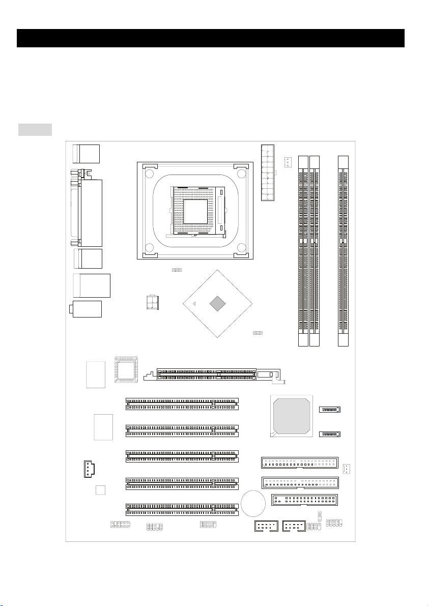
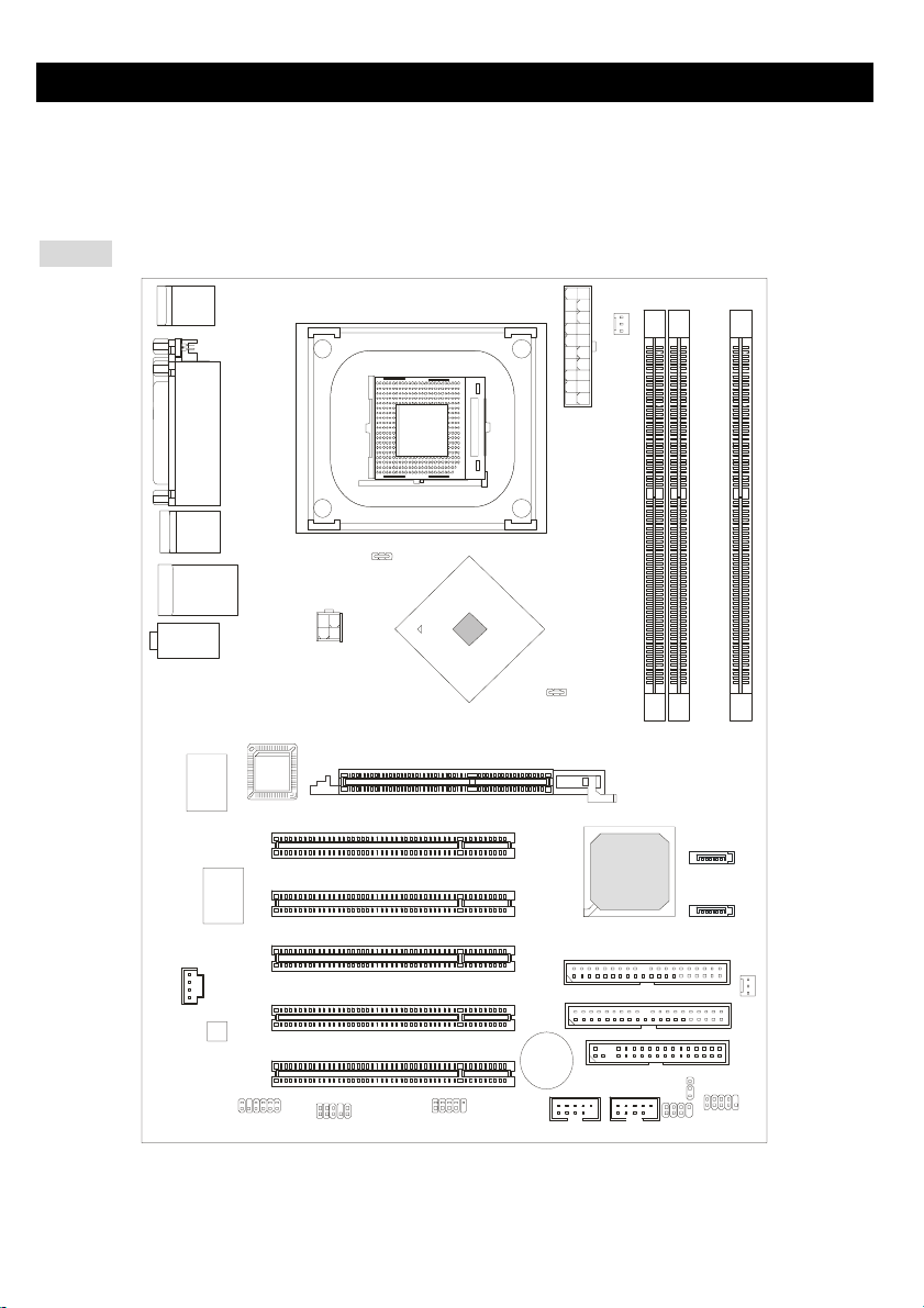
Layout
Top : mo us e
Bo tt om: k eyb oar d
Top : Para ll el P ort
Bottom:
COM A
T:S PDI F Ou t
B: US B po r t s
T:L AN jac k ( Op tio nal)
B: US B po rt s
T:Line -In
M:
Li ne -Out
B: Mi c
Winbond
W83627THF
Realtek
8110S/8100C
CD1
Code c
BIOS
JPW1
PCI Slot 1
PCI Slot 2
PCI Slot 3
PCI Slot 4
chip set
AGP Slot
SOCKET 478
Intel
865PE
ATX Powe r
Supply
ID E 2
ID E 1
CPUFAN1
I CH 5
DIMM 2
DIM M 3
SATA2
SATA 1
SYSFAN 1
DIMM 1
JS P1
JAUD1
PCI Slot 5
JDB1
865PE Neo 2 -V
1
BATT
+
USB2
USB3
JFP2
JB AT 1
FDD1
JFP1
Page 6
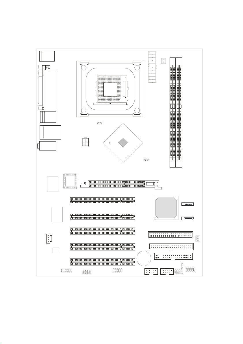
To p : mo u s e
Bottom: keyboard
Top : P arallel Port
Bottom:
COM A
T:SPDIF Out
B:USB ports
T:LA N ja ck (Opt iona l)
B :US B p ort s
T:Line-In
M:
Line-Out
B:Mic
Winbond
W83627THF
Realtek
8110S/8100C
CD1
Co de c
BIOS
JPW1
PCI S l ot 1
PCI S l ot 2
PCI S l ot 3
PCI S l ot 4
chi pset
AGP Slot
Intel
848P
CP UFA N1
SOCKET 478
ATX Powe r
Supply
DIMM 1
DIMM 2
SATA2
ICH 5
SATA1
IDE 2
IDE 1
SYSFAN1
JS P1
JAUD1
PCI S l ot 5
JD B1
848P Neo-V
2
BATT
+
USB2
USB3
JFP 2
JBAT1
FDD1
JFP1
Page 7

Specifications
CPU
z Supports Intel®P4 Northwood / Prescott (Socket 478) processors.
z FSB 400MHz (for Northwood only) / 533MHz / 800MHz depending on the North Bridge integrated.
z Supports up to 3.4GHz or higher speed P4 processor.
(For the latest information about CPU, please visit
http://www.msi.com.tw/program/products/mainboard/mbd/pro_mbd_cpu_support.php)
Chipset
z Intel® 865PE / 848P chipset
- Supports 400/533/800MHz Intel NetBurst micro-architecture bus.
- Supports AGP 8X/4X interface.
- Supports DDR266/333/400 memory interface.
z Intel® ICH5 chipset (376 BGA)
- 8 Hi-Speed USB ports (USB2.0/1.1) controller, 480Mb/sec.
- 2 Serial ATA/150 ports.
- 2 channel Ultra ATA 100 bus Master IDE controller.
- PCI Master v2.3.
- I/O APIC.
- Supports both ACPI and legacy APM power management.
Main Memory
z Supports bandwidth up to 3.2 GB/s (DDR 400) for single-channel mode and 6.4GB/s (DDR 400) for
dual-channel mode (for 865PE only).
z Supports two (for 848P) / three (for 865PE) unbuffered DIMM of 2.5 Volt DDR SDRAM.
z Supports up to 2GB (for 848P) / 3GB (for 865PE) memory size without ECC.
z Supports only x8, x16 DDR devices.
z Supports Dual-channel (for 865PE only) DDR 266/333/400 (based on DIMM 1.3).
(For the updated supporting memory modules, please visit
http://www.msi.com.tw/program/products/mainboard/mbd/pro_mbd_trp_list.php.)
Slots
z One AGP slot supports 8x/4x.
z Five 32-bit v2.3 Master PCI bus slots (supports 3.3v/5v PCI bus interface).
3
Page 8

On-Board IDE
z Dual Ultra DMA 66/100 IDE controllers integrated in ICH5.
- Supports PIO, Bus Master operation modes and can connect up to four Ultra ATA drives.
z Serial ATA/150 controller integrated in ICH5.
- Up to 150MB/sec transfer rate and can connect up to 2 Serial ATA drives.
On-Board Peripherals
z On-Board Peripherals includes.
- 1 floppy port supports 1 FDDs with 360K, 720K, 1.2M, 1.44M and 2.88Mbytes.
- 1 serial port COM1
- 1 parallel port supports SPP/EPP/ECP mode
- 8 USB 2.0 ports (Rear * 4/ Front * 4)
- 1 Line-In/Line-Out/Mic-In port
- 1 RJ45 LAN jack (Optional)
- 1 RCA SPDIF Out.
Audio
z AC97 link controller integrated in ICH5.
z 6 channels software audio codec ALC655.
- Compliance with AC97 v2.2 Spec and meet PC2001 audio performance requirement.
LAN (Optional)
z Realtek® 8110S/8100C Dual layout.
- Integrated Fast Ethernet MAC and PHY in one chip.
- Supports 10Mb/s, 100Mb/s & 1000Mb/s (it’s only for Realtek 8110S) auto-negotiation operation.
- Compliant with PCI v2.2.
- Supports ACPI Power Management.
BIOS
z The mainboard BIOS provides Plug & Play®BIOS which detects the peripheral devices and expansion
cards of the board automatically.
z The mainboard provides a Desktop Management Interface (DMI) function which records your
mainboard specifications.
Dimension
z ATX Form Factor: 29.5 cm (L) x 21.0 cm (W).
Mounting
z 6 mounting holes..
4
Page 9
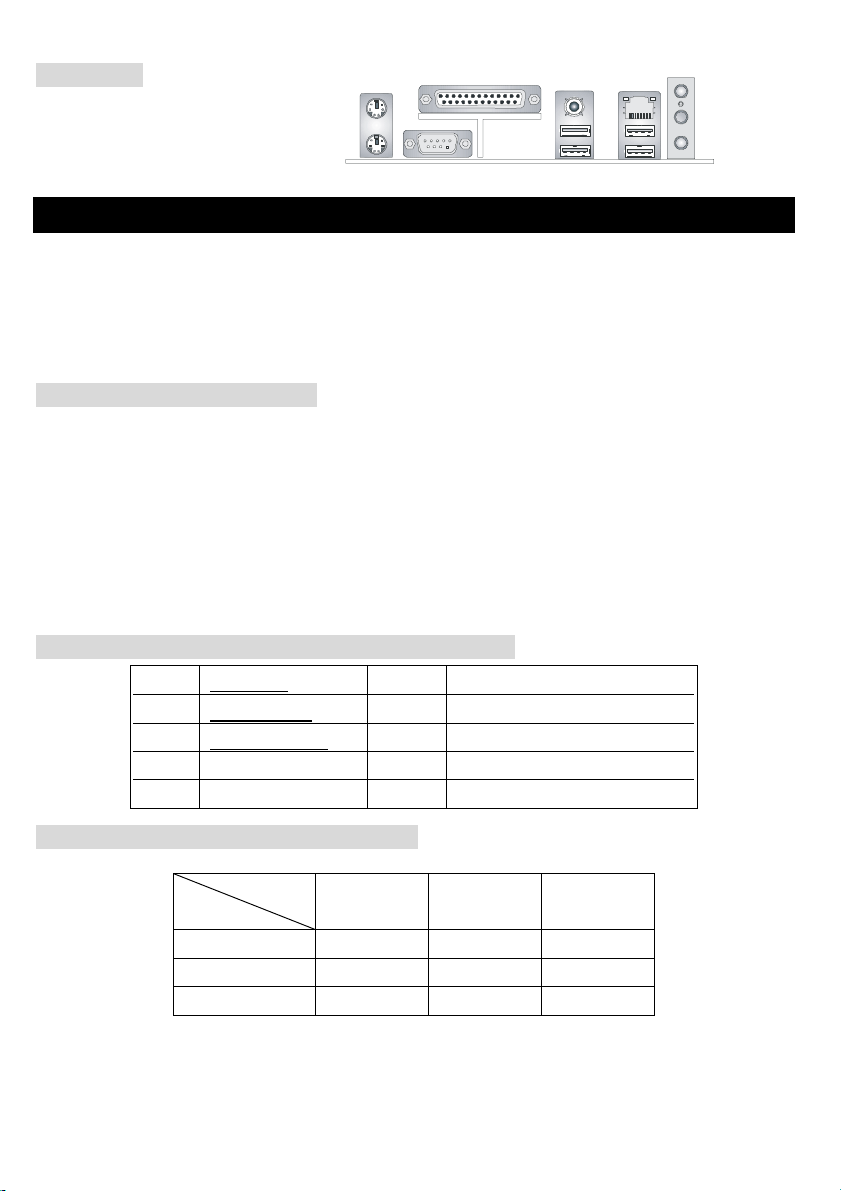
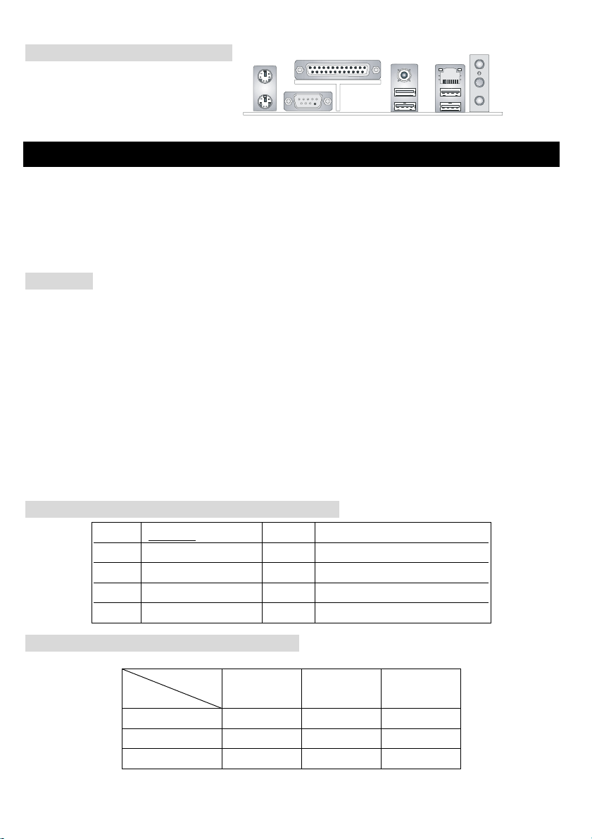
Back Panel
The back panel provides the following
connectors:
Mouse
Keyboard
COMA
Parallel
SPDIF-Out
USB Port s US B Ports
LAN
(O ptio nal)
L-in
L-out
Mic
Hardware Setup
This chapter tells you how to install the CPU, memory modules, and expansion cards, as well as how to
setup the jumpers on the mainboard. It also provides the instructions on connecting the peripheral devices,
such as the mouse, keyboard, etc. While doing the installation, be careful in holding the components and
follow the installation procedures.
Central Processing Unit: CPU
The mainboard supports Intel®Pentium®4 processors in the 478 pin package. The mainboard uses a CPU
socket called PGA478 for easy CPU installation. When you are installing the CPU, make sure the CPU has
a heat sink and a cooling fan attached on the top to prevent overheating. If you do not have the heat sink
and cooling fan, contact your dealer to purchase and install them before turning on the computer.
(For the latest information about CPU, please visit
http://www.msi.com.tw/program/products/mainboard/mbd/pro_mbd_cpu_support.php)
Example of CPU Core Speed Derivation Procedure
If CPU Clock = 200MHz
Core/Bus ratio = 12
then CPU core speed = Host Clock x Core/Bus ratio
= 200MHz x 12
= 2.4 GHz
Memory Speed/CPU FSB Support Matrix
Memory
FSB
400MHz OK N/A N/A
533MHz OK OK N/A
800MHz N/A OK OK
DDR 266 DDR333 DDR 400
5
Page 10

CPU Installation Procedures for Socket 478
1. Please turn off the power and unplug the power cord before installing the CPU.
2. Pull the lever sideways from the socket. Make sure to raise the lever up to a 90-degree angle.
3. Look for the gold arrow. The gold arrow should point towards the lever pivot. The CPU can only fit in
the correct orientation.
4. If the CPU is correctly installed, the pins should be completely embedded into the socket and can not
be seen. Please note that any violation of the correct installation procedures may cause permanent
damages to your mainboard.
5. Press the CPU down firmly into the socket and close the lever. As the CPU is likely to move while the
lever is being closed, always close the lever with your fingers pressing tightly on top of the CPU to
make sure the CPU is properly and completely embedded into the socket.
Installing the CPU Fan
As processor technology pushes to faster speeds and higher performance, thermal management becomes
increasingly important. To dissipate heat, you need to attach the CPU cooling fan and heatsink on top of the
CPU. Follow the instructions below to install the Heatsink/Fan:
1. Locate the CPU and its retention mechanism on the motherboard.
2. Position the heatsink onto the retention mechanism.
3. Mount the fan on top of the heatsink. Press down the fan until its four clips get wedged in the holes of
the retention mechanism.
4. Press the two levers down to fasten the fan. Each can only be pressed down in ONE-way.
5. Connect the power cable from the mounted fan to the 3-pin fan power connector on the board.
MSI Reminds You...
Overheating will seriously damage the CPU and system, always make sure the cooling fan can work
properly to protect the CPU from overheating.
While replacing the CPU, always turn off the ATX power supply or unplug the power supply’s power cord
from grounded outlet first to ensure the safety of CPU.
6
Page 11
Memory
The mainboard provides 2/3 slots for 184-pin, 2.5V DDR DIMM modules and supports the memory size up
to 2 GB/3GB without ECC. You can install DDR266/DDR333/DDR400 DDR SDRAM modules on the DDR
DIMM slots. To operate properly, at least one DIMM module must be installed.
(For the updated supporting memory modules, please visit
http://www.msi.com.tw/program/products/mainboard/mbd/pro_mbd_trp_list.php.)
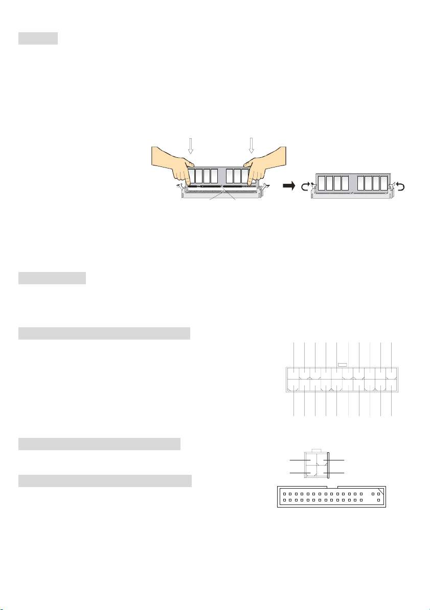
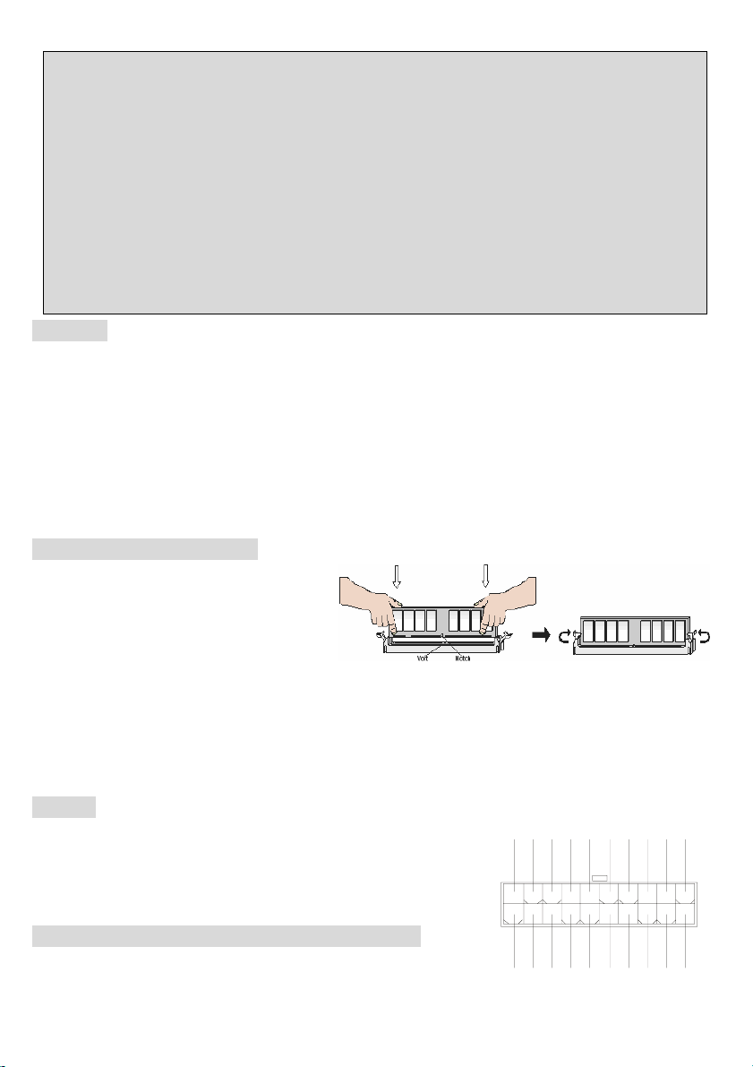
1. The DDR DIMM has only
one notch on the center of
module. The module will only fit in
the right orientation.
NotchVol t
2. Insert the DIMM memory module vertically into the DIMM slot. Then push it in until the golden finger
on the memory module is deeply inserted in the socket.
3. The plastic clip at each side of the DIMM slot will automatically close.
Power Supply
The mainboard supports ATX power supply for the power system. Before inserting the power supply
connector, always make sure all components installed properly and ensure no damage to be caused.
GND
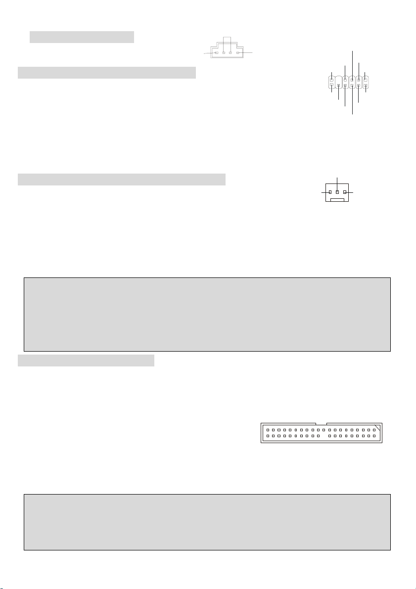
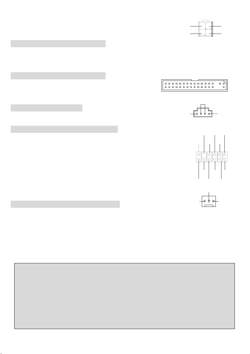
ATX 20-Pin Power Connector: ATX1
This connector allows you to connect to an ATX power supply. To
5V
-5V
5V
GND
GND
PS_ON
GND
-12V
3.3V
connect to the ATX power supply, make sure the plug of the power
supply is inserted in the proper orientation and the pins are aligned.
Then push down the power supply firmly into the connector.
ATX 12V Power Connector: JPW1
This 12V power connector is used to provide power to the CPU.
Floppy Disk Drive Connector: FDD1
The mainboard provides a standard floppy disk drive connector that
supports 360K, 720K, 1.2M, 1.44M and 2.88M floppy disk types.
7
20
10
12 V
12 V
5V _ SB
132
PW_OK
4
GND
11
1
3. 3V
GND
GND
5V
12 V
GNDGND
3.3V
5V
Page 12
CD-In Connector: CD1
T
The connector is for CD-ROM audio connector.
S-Bracket Connector: JSP1 (Optional)
The connector allows you to connect a S-Bracket for Sony & Philips Digital Interface
(SPDIF). The S-Bracket offers 2 SPDIF jacks for digital audio transmission (one for
GND
VDD3
2
1
VC C5
SPDFO
SO UT-R
SPDFO
GND
LFE -O U
SOUT-L
GND
12
11
GND
CET- OU T
R
L
optical fiber connection and the other for coaxial), and 2 analog Line-Out jacks for 4-channel audio output.
To attach the fiber-optic cable to optical SPDIF jack, you need to remove the plug from the jack first. The
two SPDIF jacks support SPDIF output only.
Fan Power Connectors: CPUFAN1/SYSFAN1
+12V
The CFAN1 (processor fan) and SFAN1 (system fan) support system cooling fan
GND
with +12V. They support three-pin head connector. When connecting the wire to the connectors, always
take note that the red wire is the positive and should be connected to the +12V, the black wire is Ground
and should be connected to GND. If the mainboard has a System Hardware Monitor chipset on-board, you
must use a specially designed fan with speed sensor to take advantage of the CPU fan control.
SENSOR
MSI Reminds You...
1. Always consult the vendors for proper CPU cooling fan.
2. CPUFAN1 supports the fan control. You can install the PC Alert utility that will automatically control the
CPU fan speed according to the actual CPU temperature.
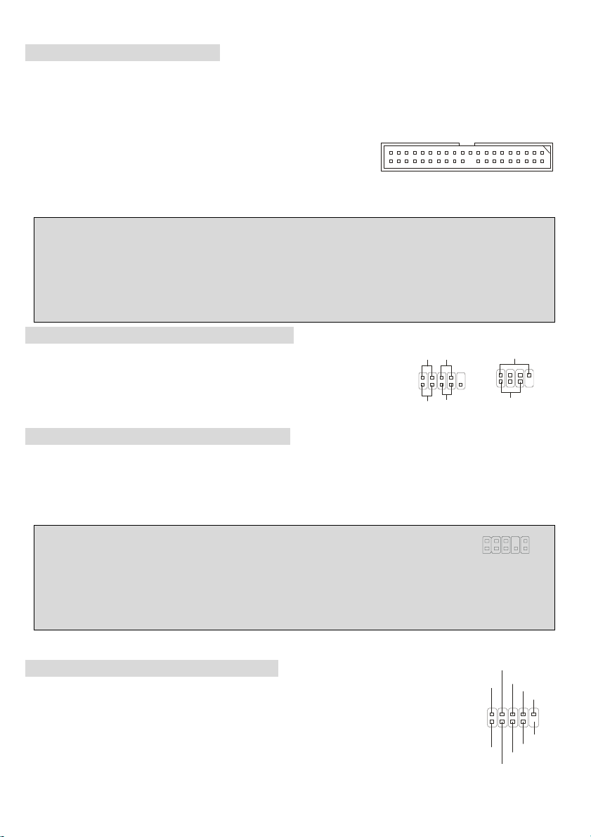
IDE Connectors: IDE1 & IDE2
The mainboard has a 32-bit Enhanced PCI IDE and Ultra DMA 33/66/100 controller that provides PIO mode
0~5, Bus Master, and Ultra DMA 33/66/100 function. You can connect up to four hard disk drives, CD-ROM,
120MB Floppy and other devices. These connectors support the provided IDE hard disk cable.
IDE1 (Primary IDE Connector):
The first hard drive should always be connected to IDE1. IDE1 can connect a Master and a Slave drive. You
must configure second hard drive to Slave mode by setting the jumper accordingly.
IDE2 (Secondary IDE Connector): IDE2 can also connect a Master and a Slave drive.
MSI Reminds You...
If you install two hard disks on cable, you must configure the second drive to Slave mode by setting its
jumper. Refer to the hard disk document supplied by hard disk vendors for jumper setting instructions.
8
Page 13
Front Panel Connectors: JFP1 & JFP2
6
1
2
The mainboard provides two front panel connectors for electrical connection
to the front panel switches and LEDs. JFP1 is compliant with Intel®Front
Panel I/O Connectivity Design Guide.
Power
LED
2
1
HD D
LED
JFP
Power
Swi t ch
Reset
Switch
JFP
Speaker
Power
LED
8
7
2
10
1
9
Front Panel Audio Connector: JAUD1
The front panel audio connector allows you to connect to the front panel audio and is compliant with Intel ®
Front Panel I/O Connectivity Design Guide.
MSI Reminds You...
Not to connect to the front audio header, pins 5 & 6, 9 & 10 should jumper in order to have signal output
10
9
5
directed to the rear audio ports. Otherwise, the Line-Out connector on the back panel will not function.
Front USB Connector: USB2&USB3
The mainboard provides two USB 2.0 pin headers JUSB2 & JUSB3 that are compliant
with Intel®I/O Connectivity Design Guide. USB 2.0 technology increases data transfer
rate up to a maximum throughput of 480Mbps, which is 40 times faster than USB 1.1,
and is ideal for connecting high-speed USB interface peripherals such as USB HDD,
digital cameras, MP3 players, printers, modems and the like.
VCC
2
1
VCC
USB1-
US B1+
US B 0 +
USB0-
GND
GND
US BOC
10
KE Y
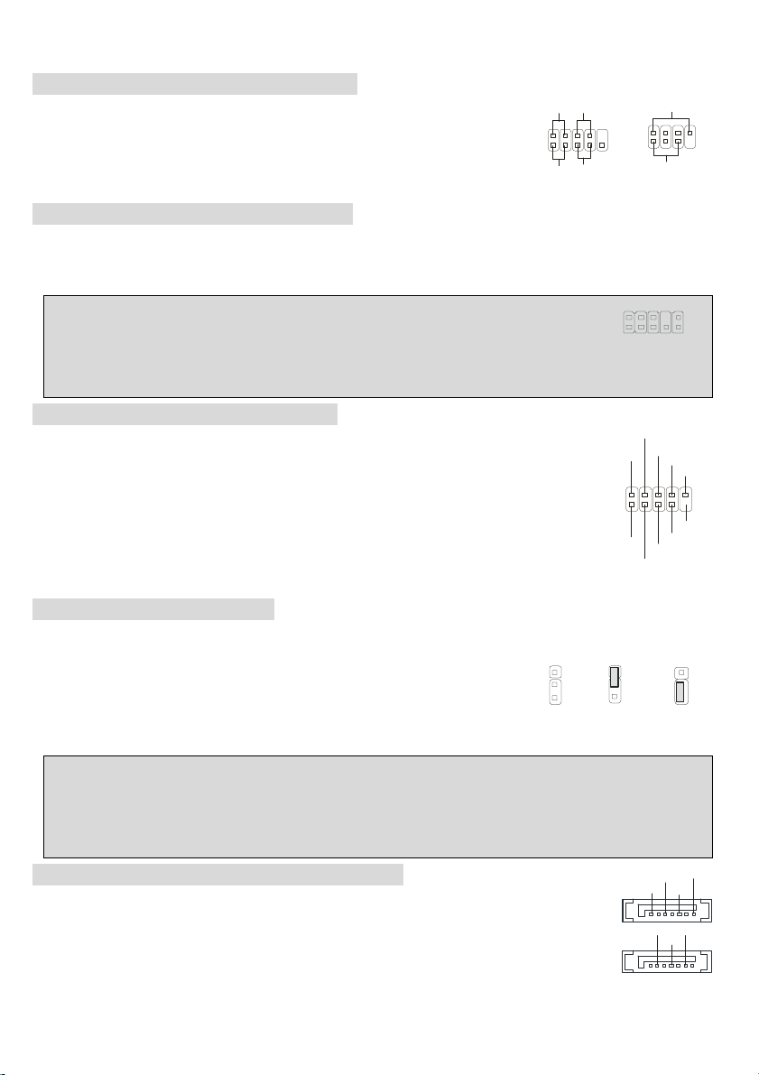
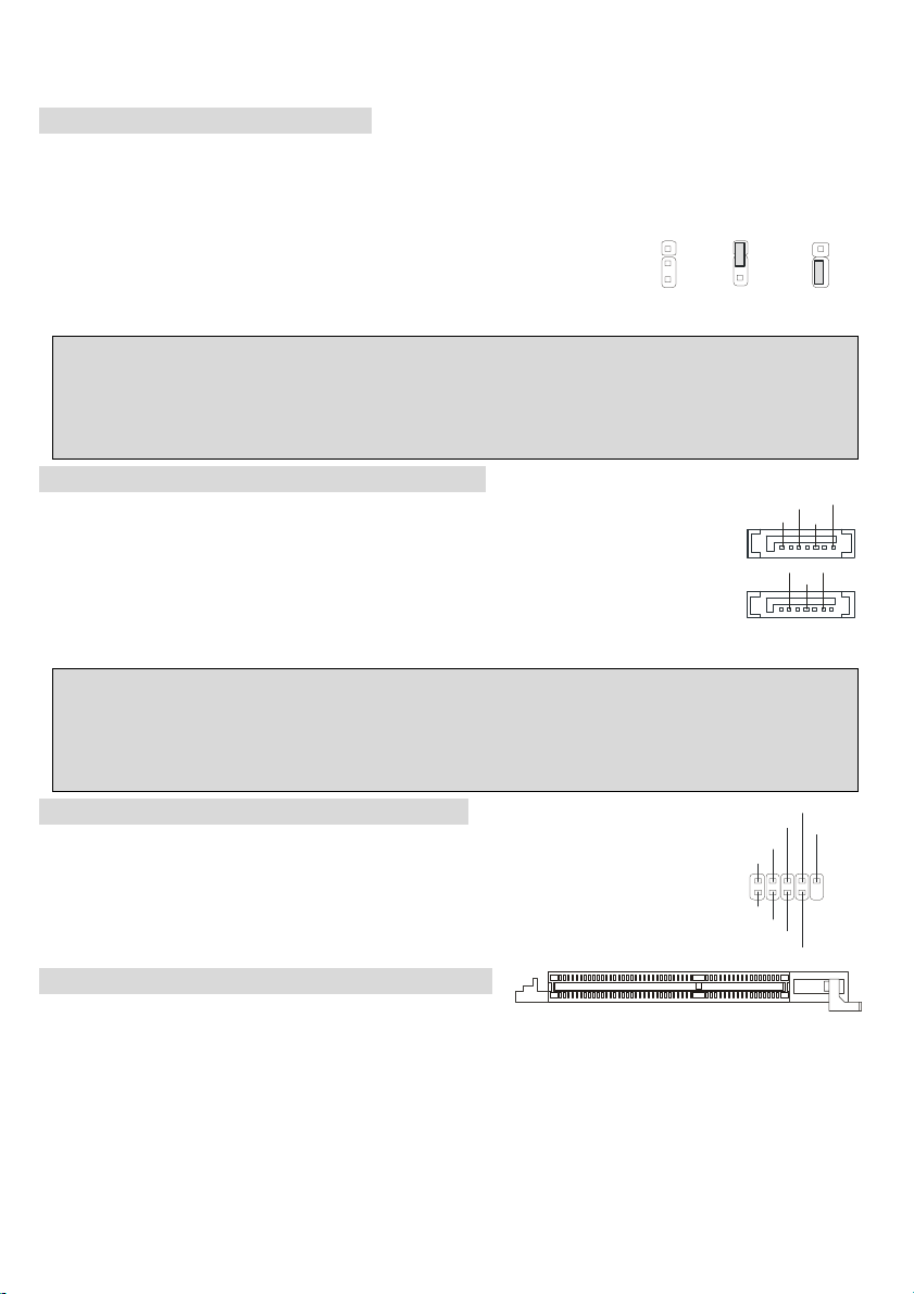
Clear CMOS Jumper: JBAT1
There is a CMOS RAM on board that has a power supply from external battery to keep the data of system
configuration. With the CMOS RAM, the system can automatically boot OS
every time it is turned on. If you want to clear the system configuration, use the
1
1
3
Kee p Data
1
3
Clear D ata
JBAT1 (Clear CMOS Jumper ) to clear data. Follow the instructions aside to clear the data:
MSI Reminds You...
9
You can clear CMOS by shorting 2-3 pin while the system is off. Then return to 1-2 pin position. Avoid
clearing the CMOS while the system is on; it will damage the mainboard.
Serial ATA HDD Connectors: SATA1, SATA2
The mainboard provides dual high-speed Serial ATA interface ports. The ports support 1st
generation Serial ATA data rates of 150MB/s and are fully compliant with Serial ATA 1.0
specifications. Each Serial ATA connector can connect to 1 hard disk drive.
9
GN D
RXP
7
RXN
GN D
GND
TXN
TX P
1
Page 14
MSI Reminds You...
Please do not fold the Serial ATA cable into 90-degree angle. Otherwise, the loss of data may occur
during transmission.
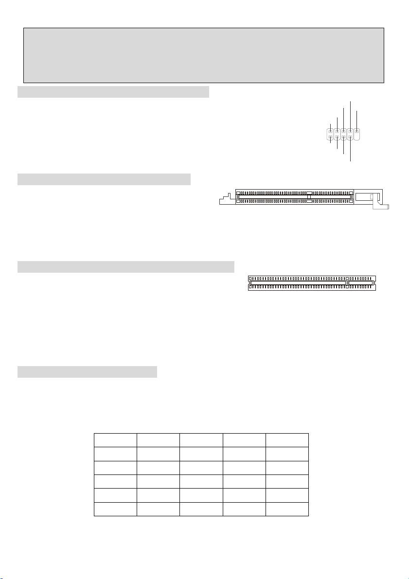
D-Bracket™2 Connector: JDB1 (Optional)
The mainboard comes with a JDB1 connector for you to connect to D-Bracket™2.
D-Bracket™2 is a USB Bracket that supports both USB1.1 & 2.0 spec. It integrates
four LEDs and allows users to identify system problem through 16 various
combinations of LED signals.
DBR4
DBR3
NC
DB R2
DB R1
210
DB G1
DB G2
DB G3
91
DB G4
AGP (Accelerated Graphics Port) Slot
The AGP slot allows you to insert the AGP graphics
card. AGP is an interface specification designed for the throughput demands of 3D graphics. It
introduces a 66MHz, 32-bit channel for the graphics controller to directly access main memory. The slot
supports 8x/4x AGP card.
PCI (Peripheral Component Interconnect) Slots
The PCI slots allow you to insert the expansion cards to meet
your needs. When adding or removing expansion cards, make sure that you unplug the power supply first.
Meanwhile, read the documentation for the expansion card to make any necessary hardware or software
settings for the expansion card, such as jumpers, switches or BIOS configuration. The orange PCI slot
(PCI5) also works as a communcation slot, which allows you to insert the communcation card.
PCI Interrupt Request Routing
The IRQ, acronym of interrupt request line and pronounced I-R-Q, are hardware lines over which devices
can send interrupt signals to the microprocessor. The PCI IRQ pins are typically connected to the PCI bus
INT A# ~ INT D# pins as follows:
Order1 Order2 Order3 Order4
PCI Slot 1 INT B# INT C# INT D# INT A#
PCI Slot 2 INT C# INT D# INT A# INT B#
PCI Slot 3 INT D# INT A# INT B# INT C#
PCI Slot 4 INT B# INT C# INT D INT A#
PCI Slot 5 INT A# INT B# INT C# INT D#
.
10
Page 15
BIOS Setup
Power on the computer and the system will start POST (Power On Self Test) process. When the
message below appears on the screen, press <DEL> key to enter Setup. DEL: Setup F11: Boot
Menu F12: Network boot TAB: Logo … If the message disappears before you respond and you still
wish to enter Setup, restart the system by turning it OFF and On or pressing the RESET button. You
may also restart the system by simultaneously pressing <Ctrl>, <Alt>, and <Delete> keys.
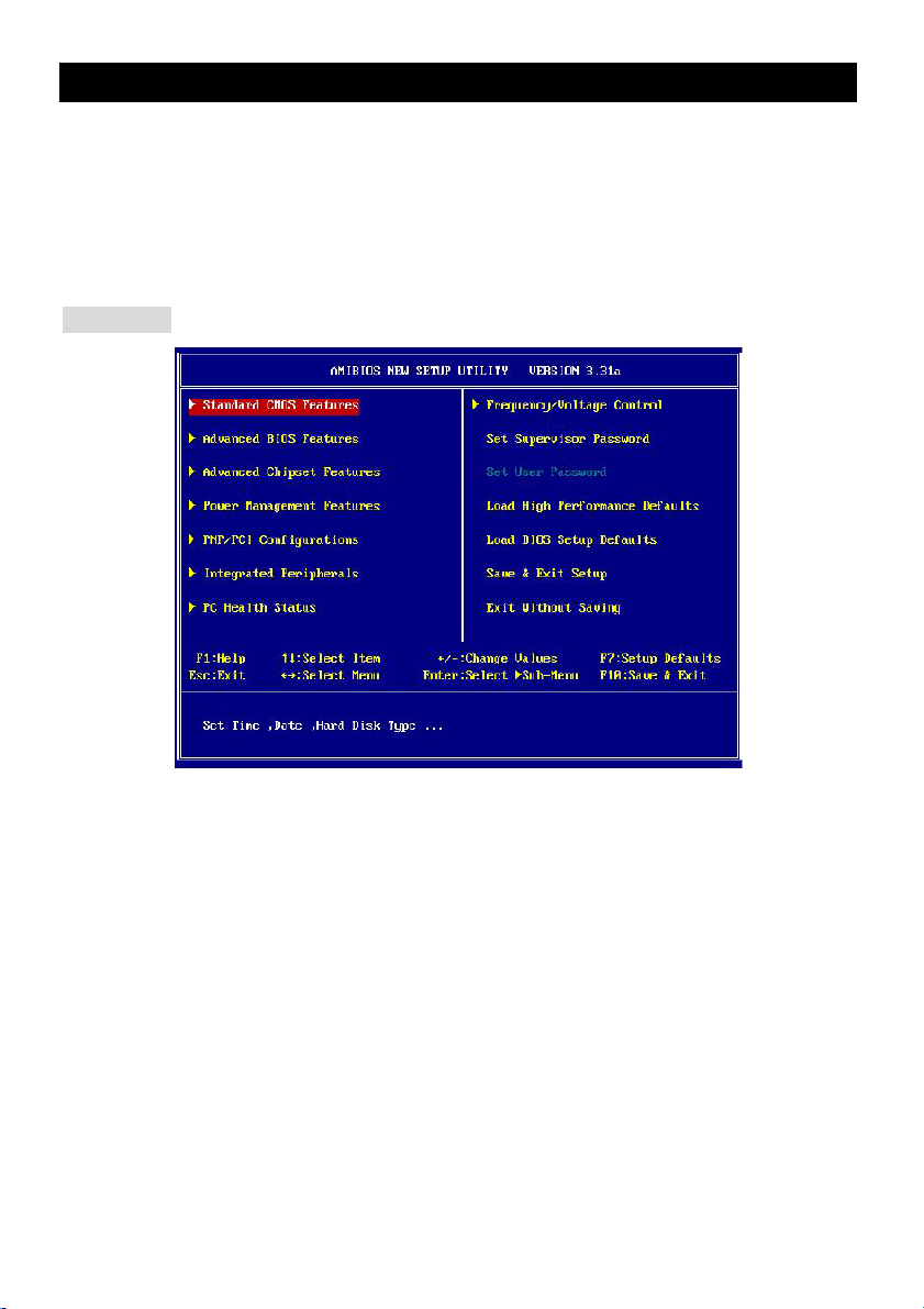
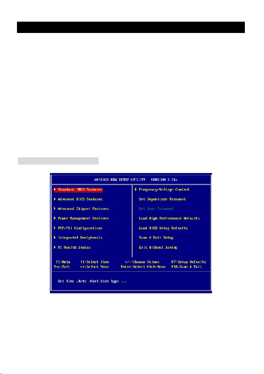
Main Page
Standard CMOS Features
Use this menu for basic system configurations, such as time, date etc.
Advanced BIOS Features
Use this menu to setup the items of AMI® special enhanced features.
Advanced Chipset Features
Use this menu to change the values in the chipset registers and optimize your system performance.
Power Management Features
Use this menu to specify your settings for power management.
PNP/PCI Configurations
This entry appears if your system supports PnP/PCI.
Integrated Peripherals
Use this menu to specify your settings for integrated peripherals.
PC Health Status
This entry shows your PC health status.
Frequency/Voltage Control
Use this menu to specify your settings for frequency/voltage control.
Set Supervisor Password
11
Page 16
Use this menu to set Supervisor Password.
Set User Password
Use this menu to set User Password.
Load High Performance Defaults
Use this menu to load the BIOS values for the best system performance, but the system stability may
be affected.
Load BIOS Setup Defaults
Use this menu to load factory default settings into the BIOS for stable system performance operations.
Save & Exit Setup
Save changes to CMOS and exit setup.
Exit Without Saving
Abandon all changes and exit setup.
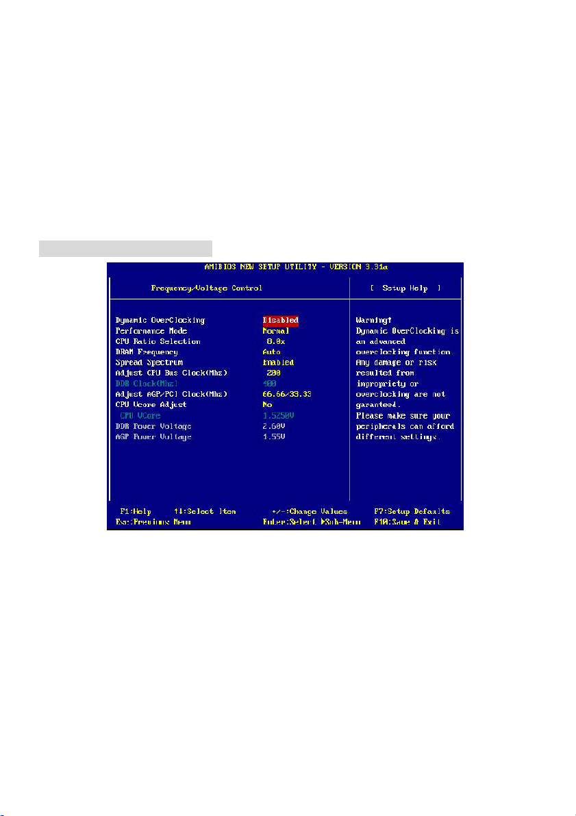
Frequency/Voltage Control
Dynamic OverClocking
Dynamic Overclocking Technology is the automatic overclocking function, included in the MSITM
newly developed CoreCellTM Technology. It is designed to detect the load balance of CPU while
running programs, and to adjust the best CPU frequency automatically. When the motherboard detects
CPU is running programs, it will speed up CPU automatically to make the program run smoothly and
faster. When the CPU is temporarily suspending or staying in the low load balance, it will restore the
default settings instead. Usually the Dynamic Overclocking Technology will be powered only when
users' PC need to run huge amount of data like 3D games or the video process, and the CPU
frequency need to be boosted up to enhance the overall performance. Setting options:
12
Page 17

[Disabled] Disable Dynamic Overclocking.
[Private] 1st level of overclocking.
[Sergeant] 2nd level of overclocking.
[Captain] 3rd level of overclocking, also default of Load High Performance Defaults.
[Colonel] 4th level of overclocking.
[General] 5th level of overclocking.
[Commander] 6th level of overclocking.
Performance Mode
Allows you to control the MAT (memory acceleration technology) function of CPU. MAT is MSITM
exclusive technology, specialized in optimizing the data transfer rate among CPU, N/B chip and
memory, and also in procuring better memory performance and bandwidth up to 10%. Selecting [Fast]
enables MAT. Note that not every memory is compatible with MAT. If the system fail to reboot for four
times, the BIOS will be restored to the Default value ([Normal]). Setting options: [Normal], [Fast].
CPU Ratio Selection
This setting controls the multiplier that is used to determine the internal clock speed of the processor
relative to the external or motherboard clock speed.
DRAM Frequency
Use this field to configure the clock frequency of the installed DRAM. Settings are:
PSB 400: [100-355MHz] PSB 533: [133-500MHz] PSB 800: [200-500MHz]
Spread Spectrum
When the motherboard clock generator pulses, the extreme values (spikes) of the pulses creates
EMI (Electromagnetic Interference). The Spread Spectrum function reduces the EMI generated by
modulating the pulses so that the spikes of the pulses are reduced to flatter curves. If you do not have
any EMI problem, leave the setting at [Disabled] for optimal system stability and performance. But if
you are plagued by EMI, activate the Spread Spectrum for EMI reduction. Remember to disable
Spread Spectrum if you are overclocking because even a slight jitter can introduce a temporary boost
in clock speed which may just cause your overclocked processor to lock up. Options: [Disabled],
[Enabled].
Adjust CPU Bus Clock (Mhz)
This item allows you to select the CPU Bus clock frequency (in MHz) and overclock the processor by
adjusting the FSB clock to a higher frequency. Also the setting you choose will change color for
warning if the value is of over the specifications.
DDR Clock (Mhz)
This read-only item allows you to view the current DDR clock.
13
Page 18

Adjust AGP/PCI Clock (Mhz )
This item allows you to select the AGP/PCI clock frequency (in MHz) by adjusting the AGP/PCI clock
to a higher frequency.
CPU Vcore Adjust
The setting allows you to adjust the CPU Vcore voltage. Available options: [Yes], [No].
CPU Vcore
The setting is adjustable if you set the CPU Vcore Adjust to [Yes] .
MSI Reminds You...
Changing CPU Ratio/Vcore could result in the instability of the system; therefore, it is NOT
recommended to change the default setting for long-term usage.
DDR Power Voltage
Adjusting the DDR voltage can increase the DDR speed. Any changes made to this setting may cause
a stability issue, so changing the DDR voltage for long-term purpose is NOT recommended.
AGP Power Voltage
AGP voltage is adjustable in the field, allowing you to increase the performance of your AGP display
card when overclocking, but the stability may be affected.
MSI Reminds You...
The settings shown in different color in CPU Vcore (V), DDR Power Voltage (V) and AGP Power
Voltage (V) helps to verify if your setting is proper for your system.
White: Safe setting.
Yellow: High performance setting.
Red: Not recommended setting and the system may be unstable..
14
Page 19
Einleitung
Vielen Dank für den Kauf 848P Neo-V/865PE Neo2-V (MS-6788 v2.X) Serie ATX Mainboard. Die 848P
Neo-V/865PE Neo2-V Serie sind Mainboards basiert auf Intel® 848P/865PE & ICH5 Chipsatz für optimale
Systemeffizienz. Entwickelt, für den für fortschrittlichen Intel ® Pentium ® 4 Prozessor im 478 Pin Gehäuse, liefert 848P Neo-V/865 PE Neo2-V Series hohe Perfomance für eine proffessionelle Desktop-PC
Lösung.
Layout
Top : mo us e
Bo tt om: k eyb oar d
Top : Para ll el P ort
Bottom:
COM A
T:S PDI F Ou t
B: US B po r t s
T:L AN jac k ( Op tio nal)
B: US B po rt s
T:Line -In
M:
Li ne -Out
B: Mi c
Winbond
W83627THF
Realtek
8110S/8100C
CD1
Code c
BIOS
JPW1
PCI Slot 1
PCI Slot 2
PCI Slot 3
PCI Slot 4
chip set
AGP Slot
SOCKET 478
Intel
865PE
ATX Powe r
Supply
ID E 2
ID E 1
CPUFAN1
I CH 5
DIMM 2
DIM M 3
SATA2
SATA 1
SYSFAN 1
DIMM 1
JS P1
JAUD1
PCI Slot 5
JDB1
865PE Neo 2 -V
15
BATT
+
USB2
USB3
JFP2
JB AT 1
FDD1
JFP1
Page 20

To p : mo u s e
Bottom: keyboard
Top : P arallel Port
Bottom:
COM A
T:SPDIF Out
B:USB ports
T:LA N ja ck (Opt iona l)
B :US B p ort s
T:Line-In
M:
Line-Out
B:Mic
Winbond
W83627THF
Realtek
8110S/8100C
CD1
Co de c
BIOS
JPW1
PCI S l ot 1
PCI S l ot 2
PCI S l ot 3
PCI S l ot 4
chi pset
AGP Slot
Intel
848P
CP UFA N1
SOCKET 478
ATX Powe r
Supply
DIMM 1
DIMM 2
SATA2
ICH 5
SATA1
IDE 2
IDE 1
SYSFAN1
JS P1
JAUD1
PCI S l ot 5
JD B1
848P Neo-V
16
BATT
+
USB2
USB3
JFP 2
JBAT1
FDD1
JFP1
Page 21

Spezifikationen
CPU
z Unterstützt Intel
z FSB 400 (nur für Northwood), 533, 800 (nur für PT880/PT800 only) MHz
z Unterstützt bis 3.4GHz oder schneller
(Für die neuesten CPU-Kompatiblitäts-Informationen besuchen Sie bitte die folgende Webseite:
http://www.msi.com.tw/program/products/mainboard/mbd/pro_mbd_cpu_support.php )
Chipsatz
z Intel® 865PE / 848P Chipsatz
- Unterstützt 400/533/800MHz Intel NetBurst Microarchitektur
- Unterstützt AGP 8X/4X Schnittstelle.
- Unterstützt DDR266/333/400 Speicherschnittstelle.
z Intel® ICH5 Chipsatz (376 BGA)
- 8 Hochgeschwindigkeits-USB-Anschlüsse (USB2.0/1.1), 480Mbit/s
- 2 Serial ATA/150 Anschlüsse.
- 2 Kanal Ultra ATA 100 Bus Master IDE Kontroller.
- PCI Master v2.3.
- I/O APIC.
- Unterstützt ACPI und APM Power Management.
Hauptspeicher
z Unterstützt eine Speicherbandbreite bis 3.2 GB/s (DDR 400) im Einkanal- und 6.4GB/s (DDR 400) im
Zweikanal-Modus (nur bei 865PE Chipsatz).
z Unterstützt zwei (bei 848P) / drei (bei 865PE) ungepufferte 2.5 Volt DIMMs.
z Unterstützt bis zu 2GB (bei 848P) / 3GB (bei 865PE) Speichergröße ohne ECC.
z Unterstützt nur x8, x16 DDR Speicherarchitektur.
z Unterstützt Zweikanal (nur 865PE) DDR 266/333/400 bei Bestückung von DIMM 1 und 3.
(Für die neuesten Speicher-Kompatiblitäts-Informationen besuchen Sie bitte die folgende Webseite:
http://www.msi.com.tw/program/products/mainboard/mbd/pro_mbd_trp_list.php )
Steckplätze
z Ein AGP (Accelerated Graphics Port) Steckplatz unterstützt 8x/4x (AGP 3.0) mit 1.5V (3.3V wird nicht
unterstützt)
z Fünf 32-bit Master PCI Bus Steckplätze (Unterstützt 3.3v/5v PCI Bus Schnittstelle)
®
P4 Northwood/Prescott (Socket 478) Prozessoren
17
Page 22

On-Board IDE
z Zwei Ultra DMA 66/100 IDE Kontrollers im ICH5 integriert.
- Unterstützt PIO und Bus Master Modus, es können bis zu 4 IDE Laufwerke angeschlossen werden.
z Serial ATA/150 Kontroller im ICH5 integriert.
- Bis zu 150MB/s Transferrate, es können bis zu 2 Serial ATA Laufwerke angeschlossen werden.
On-Board Peripherie
z On-Board Peripherie beinhaltet.
- 1 Floppy Anschluss, unterstützt 1 Floppy mit 360K, 720K, 1.2M, 1.44M und 2.88Mbytes.
- 1 Serieller Anschluß COM1
- 1 Paralleler Anschluß, unterstützt SPP/EPP/ECP Modus
- 8 USB 2.0 Anschlüsse (Rückseite * 4/ Front * 4)
- 1 Audio-Ein/Ausgang und Mikrofon-Anschluss
- 1 RJ45 Netzwerkanschluss (Optional)
- 1 RCA SPDIF digitaler Audio-Ausgang.
Audio
z AC97 Link Kontroller in ICH5 integriert.
z 6 Kanal Software Audio Codec ALC655.
- Entspricht den AC97 v2.2 Spezifikationen und den PC2001 Audio Anforderungen.
Netzwerk (Optional)
z Realtek® 8110S oder 8100C.
- Integrierter Ethernet MAC und PHY in einem Chip.
- Unterstützt 10Mb/s, 100Mb/s & 1000Mb/s (Nur bei Realtek 8110S) mit automtischer Erkennung.
- Entspricht PCI v2.2 Spezifikation.
- Unterstützt ACPI Power Management.
BIOS
z Das Mainboard stellt ein “Plug & Play” BIOS, welches angeschlossene Geräte und Erweiterungskarten
automatisch erkennt, zur Verfügung.
z Das Mainboard stellt die Desktop Management Interface (DMI) Funktionen zur Verfügung, welche die
Systemspezifikationen aufzeichnet.
Dimension
z ATX Form Faktor: 29.5 cm (B) x 21.0 cm (T).
Befestigung
z 6 Befestigungslöcher.
18
Page 23
Anschlüsse auf der Rückseite
Folgende Anschlüsse stehen auf der
Rückseite zur Verfügung:
Mouse
Keyboard
COMA
Parallel
SPDIF-Out
USB Port s US B Ports
LAN
(O ptio nal)
L-in
L-out
Mic
Hardware Einrichtung
Dieses Kapitel beschreibt Ihnen, wie CPU, Speichermodule und Erweiterungskarten eingesetzt werden,
und wie Jumper auf dem Mainboard eingestellt werden. Es beinhaltet auch die Anleitung, wie Sie
Peripheriegeräte wie Maus, Tastatur, usw. anschließen. Während der Installation behandeln Sie bitte die
Komponenten vorsichtig und folgen Sie genau der Anleitung.
Prozessor
Das Mainboard unterstützt Intel Pentium 4 Northwood & Prescott und Celeron Prozessoren in der Sockel
478 Bauform. Dazu hat es einen PGA478 Sockel für die leichte CPU Installation. Um den Prozessor vor
Überhitzung zu schützen, stellen Sie sicher, dass Sie einen geeigneten CPU-Kühler mit Lüfter auf dem
Prozessor installieren.. Wenn Sie keinen geeigneten Kühler für Ihren Prozessor haben sollten, kontaktieren
Sie Ihren Händler, um ein passendes Modell erwerben. Bitte schalten Sie den PC nicht ein, wenn Sie
keinen geeigneten Kühler installiert haben. (Für die neuesten CPU-Kompatiblitäts- Informationen besuchen
Sie bitte die folgende Webseite:
http://www.msi.com.tw/program/products/mainboard/mbd/pro_mbd_cpu_support.php )
Beispiel für die Ermittlung des CPU-Kerntaktes
Wenn CPU Takt = 200MHz
Taktmultiplikator = 12
dann CPU Kerntakt = Ext. Takt x Taktmultiplikator
= 200MHz x 12
= 2.4 GHz
Speicher Speed/CPU FSB Support Matrix
Speicher
400MHz OK Nein Nein
533MHz OK OK Nein
800MHz Nein OK OK
DDR 266 DDR333 DDR 400
19
Page 24

CPU Installationsprozedur für Sockel 478
1. Bitte schalten Sie den PC aus und ziehen das Netzkabel ab, bevor Sie die CPU einsetzen.
2. Klappen Sie den Hebel am CPU-Sockel auf. Stellen Sie sicher, dass er im 90 Grad Winkel
aufgeklappt ist.
3. Sehen Sie den goldenen Pfeil an der CPU?. Dieser Pfeil muss zum Hebelmechanismus des Sockels
zeigen. Die CPU darf nur in der richtigen Richtung eingesetzt werden.
4. Sobald die CPU richtig eingesetzt ist, sind die Anschlussbeine der CPU komplett im Sockel
eingesteckt. Das Einsetzen erfolgt ohne Kraftanwendung. Bitte beachten Sie, dass eine falsche
Installation des Prozessors Ihr Mainboard und Ihren Prozessor beschädigen können.
5. Drücken Sie noch mal auf die CPU und klappen dann den Hebel herunter. Während Sie den Hebel
herunterklappen, bewegt sich die CPU noch ein wenig nach vorne. Der Hebel ist in der Endposition,
wenn er fühlbar einrastet. Der Hebel lässt sich sehr leicht bewegen. Wenn es klemmt, prüfen Sie
nochmals den korrekten Sitz der CPU.
Installation des CPU-Kühlers
Da die Prozessortechnologie sich mit großen Schritten bei den Taktraten und der Arbeitsgeschwindigkeit
weiterentwickelt, wird die effiziente Prozessorkühluung immer wichtiger. Um die Wärme abzuführen,
müssen Sie einen CPU-Kühler mit Lüfter auf die CPU aufsetzen. Folgen Sie der Anleitung, um den Kühler
auf die CPU aufzusetzen.:
1. Lokalisieren Sie die CPU und den Befestigungsrahmen für den Kühler auf dem Mainboard.
2. Setzen Sie den Kühler in den Rahmen ein.
3. Falls erforderlich, befestigen Sie den Lüfter auf dem Kühler. Beachten Sie dabei die
Montagehinweise des Kühlerherstellers. Drücken Sie den Kühler in den Rahmen, bis er einrastet..
4. Drücken Sie die beiden Hebel des Kühlers herungter, bis sie einrasten. Bitte beachten Sie dabei die
Hinweise des Kühlerherstellers.
5. Schliessen Sie das Versorgungskabel des Lüfters an dem 3-poligen Anschluss des Mainboards an.
Er ist mit CPUFAN1 beschriftet.
20
Page 25
MSI erinnert Sie...
Überhitzung…
Überhitzung beschädigt Ihre CPU und ds gesamte System ernsthaft, stellen Sie daher sicher, dass die
Lüfter immer funktionieren, um die CPU und das System vor Schäden zu bewahren.
Die CPU tauschen…
Wenn Sie die CPU tauschen, schalten Sie das System ab und ziehen den Netzstecker. Bevor Sie das
Mainboard oder die CPU anfassen, erden Sie sich, in dem Sie kurz geerdeten Gegenstand (z.B.
Heizung) berühren. Dadurch vermeiden Sie Defekte an der Hardware durch statische Aufladung.
Speicher
Das Mainboard stellt 2/3 Steckplätze für 184-Pin, 2.5V DDR DIMM Module zur Verfügung und unterstützt
eine Speichergröße von bis zu 2 GB / 3GB ohne ECC. Sie können DDR266/DDR333/DDR400 DDR
SDRAM Module in den DDR DIMM Steckplätzen einsetzen. Damit das System funktioniert, muss
wenigstens ein DIMM eingesetzt werden.
(Für die neuesten Speicher-Kompatiblitäts-Informationen besuchen Sie bitte die folgende Webseite:
http://www.msi.com.tw/program/products/mainboard/mbd/pro_mbd_trp_list.php )
Speichermodule einsetzen
1. Das DDR DIMM Modul hat in der Mitte
eine Nase, die verhindern soll, dass
Sie das Modul in der falschen Richtung
einsetzen.
2. Setzen Sie das Modul senkrecht in den Sockel ein, bis die goldenen Kontakte komplett im Sockel
versinken.
3. Die weißen Verriegelungshebel an der Seite schließen sich automatisch und rasten ein.
Netzteil
Das Mainboard unterstützt ATX Netzteile für die Stromversorgung. Befor
5V
GND
GND
5V
-5V
GND
PS_ON
GND
-12V
3.3V
Sie das System einschalten, vergewissern Sie sich, dass alle
Komponenten richtig eingesetzt wurden.
20
10
ATX Netzteilanschluss mit 20Kontakten: ATX1
An diesem Anschluss schließen Sie das Netzteil an. Der Netzteilstecker
12 V
5V _ SB
PW_OK
GND
5V
3.3V
3. 3V
GND
GND
5V
21
11
1
Page 26
lässt sich nur in einer Richtung einstecken. Drücken Sie den Stecker in den
Anschluss, bis er einrastet.
12V
4
12V
GNDGND
132
ATX 12V Stromversorgung: JPW1
Dieser 12V Stromanschluss versorgt die CPU mit Strom. Auch dieser Stecker lässt sich nur in eine Richtung
einsetzen.
Floppylaufwerk-Anschluss: FDD1
Das Mainboard stellt einen Floppyanschluss zur Verfügung, an dem
ein Laufwerk mit 360K, 720K, 1.2M, 1.44M und 2.88M Kapazität angeschlossen werden kann.
CD-Audio-Eingang: JCD1
GND
R
L
Hier können Sie das Audiokabel Ihres CD-Laufwerks anschließen.
S-Bracket Anschluss: JSP1 (Optional)
Dieser Anschluss erlaubt Ihnen die Benutzung des S-Bracket für Sony & Philips
Digital Interface (SPDIF). Das S-Bracket bietet 2 SPDIF Stecker für digitale
Audio-Übertragung (Einmal optische Glasfaserverbindung und der andere Coaxial),
und 2 analoge Audio-Ausgänge für 4-Kanal Audio Ausgabe.
Um den optischen SPDIF anzuschliessen, müssen Sie vom D-Bracket den
schwarzen Schutzstecker abziehen
Lüfteranschlüsse: CPUFAN1/SYSFAN1
2
1
GND
VDD3
VC C5
(No Pin)
SPDF 0
SPDFI
GND
+12V
SOUT-R
LFE-OUT
GND
SOUT-L
12
11
GND
CE T-OUT
SENSOR
Der CFAN1 (CPU-Lüfter) und SFAN1 (System Lüfter) untesrtützen Lüfter mit +12V Betriebsspannung.
Diese müssen einen dreipüoligen Anschluss haben. Beim Anschliessen beachten, dass das rote Kabel im
Stecker immer mit dem 12-Anschluss des Steckers, der schwarze mit Masse des Steckers verbunden wird.
Da das Mainboard mit Hardware monitor ausgestattet ist, müsen Sie spezielle Lüfter mit Speed-Signal
verwenden, damit die Lüftergeschwindigkeit ausgewertet und gesteuert werden kann .
MSI erinnert Sie...
1. Verwenden Sie stets einen geeigneten CPU-Lüfter und beachten Sie die Einbauhinweise in diesem
Handbuch und in der Lüfterdokumentation.
2. CPUFAN1 unterstützt die Geschwindigkeitsregelung des Prozessorlüfters. Sobald Sie von der
Treiber-CD das Windows-Programm PC-Alert installiert haben, wird diese Regelung aktiviert. PC-Alert
regelt die Lüfterdrehzahl anhand der CPU-Temperatur.
22
Page 27
IDE Anschlüsse: IDE1 & IDE2
1
2
6
Das Mainboard hat einen 32-bit erweiterten PCI IDE und Ultra DMA 33/66/100/133 Controller, welcher die
PIO Modis 0~4, Bus Master, und Ultra DMA 33/66/100/133 Funktion zur Verfügung stellt. Sie können bis zu
vier IDE-Festplatten, CD-ROM, 120MB Floppys und andere Geräte anschließen.
IDE1 (Primärer IDE Anschluss):
Das erste Laufwerk sollte an IDE1 angeschlossen werden. IDE1 unterstützt Master und Slave-Laufwerke.
IDE2 (Sekundärer IDE Anschluss): IDE2 unterstützt Master und Slave Laufwerke.
MSI erinnert Sie...
Wenn Sie zwei IDE-Laufwerke an einem IDE-Kabel anschließen, so müssen Sie das erste Laufwerk als
Master und das zweite Laufwerk als Slave konfigurieren. Sie erfahren aus der Dokumentation der
Laufwerke, wie diese Einstellung gemacht wird.
Gehäusefront-Anschlüsse: JFP1 & JFP2
Das Mainboard hat Anschlüsse für Bedienelemente und Statusanzeigen an
der Vorderseite des gehäuses. Hierzu gehören Anzeige LEDs und Taster.
JFP1 entspricht dem “Intel Front Panel I/O Connectivity Design Guide”.
Power
2
1
LED
HD D
LED
JFP
Power
Swi t ch
Reset
Switch
JFP
Speaker
2
10
1
9
Power
LED
Gehäusefront Audio-Anschluss: JAUD1
Der JAUD1 Gehäusefront-Anschluss erlaubt es Ihnen, Audio-Anschlüsse an der Vorderseite Ihres
Gehäuses mit dem Mainboard zu verbinden. Der Anschluss entspricht dem “Intel ® Front Panel I/O
Connectivity Design Guide”.
MSI erinnert Sie...
Wenn Sie diesen Audioanschluss nicht verwenden möchten, so müssen die Kontakte 5 & 6, 9 & 10
5
jeweils mit einem Jumper geschlossen sein, damit der hintere Audio-Ausgang des Mainboards
funktioniert.
Front USB Anschlüsses: USB2&USB3
Das Mainboard stellt zwei interne USB 2.0 Anschlüsse JUSB2 & JUSB3, welche dem
Intel®I/O Connectivity Design Guide entsprechenUSB 2.0 Technologie ermöglicht eine
Datentransferrate bis zu einem Maximum von 480 Mbps, was 40 mal schneller ist als
USB 1.1. Somit ist USB 2.0 ideal um schnelle USB-Geräte wie Digitalkameras, MP3 Player,
VCC
2
1
VCC
USB1-
US B1+
US B 0 +
USB0-
10
GND
GND
8
7
9
US BOC
KE Y
10
9
23
Page 28
Drucker, Modems und ähnliches.
CMOS Rücksetz-Jumper: JBAT1
Im Mainboard ist ein CMOS Speicher integriert, welches von einer Batterie versorgt wird, um die
Systemkonfiguration zu speichern. Das CMOS RAM ermöglicht es, das System automatisch zu starten,
ohne dass die Konfiguration neu eingestellt werden muss. Wenn Sie die
CMOS-Konfiguration löschen wollen, setzen Sie im ausgeschalteten Zustand
1
1
3
Kee p Data
Clear D ata
den Jumper JBAT1 von Position 1-2 auf 2-3 um.
MSI erinnert Sie...
Schalten Sie den PC vor dem Umsetzen des Jumpers aus. Setzen Sie den Jumper nach ein paar
Sekunden wieder in 1-2 zurück und schalten erst dann den PC wieder ein.
Serial ATA HDD Connectors: SATA1, SATA2
RXN
Das Mainboard stellt zwei unabhängige SATA –Schnittstellen für den Anschluß von bis zu
zwei Serial ATA (Serial ATA RAID) Laufwerken. Beide Anschlüsse unterstützen die 1.
Generation von SATA-Laufwerken mit einer Übertragungsrate von bis zu 150 MB/s und
sind konform mit der Serial ATA 1.0 Spezifikation.
GN D
RXP
7
GN D
MSI erinnert Sie...
Bitte falten Sie die Serial ATA Kabel nicht im 90 Grad Winkel.. Ansonsten ware ein Datenverlust bei der
Übertragung zum Laufwerk möglich.
D-Bracket™2 Anschluss: JDB1 (Optional)
Das Mainboard hat einen JDB1 Stecker für den Anschluss des D-Bracket™2.
D-Bracket™2 ist ein USB Bracket, welches USB1.1 & 2.0 unterstützt. Es integroiert 4
LEDs und erlaubt damit die Erkennung von Systemsproblemen beim Start des PC.
DBR4
DBR3
DB R2
DB R1
210
DB G1
DB G2
DB G3
DB G4
AGP (Accelerated Graphics Port) Steckplatz
1
3
GND
TXN
TX P
1
NC
91
In den AGP Steckplatz können Sie eine AGP-Grafikkarte einsetzen. AGP
ist eine Schnittstelle, deren Spezifikation für den Datendurchsatz von schnellen 3D-Grafuikkarten entwickelt
wurde. AGP ermöglicht 66MHz, 64-Bit Datenübertragung für den Grafik-Kontroller direkt zum
Hauptspeicher. Das Mainboard unterstützt AGP-Grafikkarten mit 4x/8x Übertragung und 1.5V AGP
Betriebsspannung.
24
Page 29
PCI (Peripheral Component Interconnect) Steckplätze
Ein PCI Steckplatz erlaubt es Ihnen, für Sie erforderliche
PCI-Erweiterungskarten in das System einzusetzen. Wenn Sie Erweiterungskarten einsetzen oder
entfernen, stellen Sie sicher, dass Sie vorher den PC ausschalten und den Netzstecker abziehen. Lesen
Sie auch die Dokumentation der Erweiterungskarte bezüglich Hinweisen des Herstellers zum Einbau und
möglichen Hardware- und Softwareeinstellungen. Der orangene PCI Steckplatz (PCI5) funktioniert auch als
Kommunikations-Steckplatz mit speziellen Kommunikationskarten von MSI.
PCI Interrupt Request Routing
The IRQ, acronym of interrupt request line and pronounced I-R-Q, are hardware lines over which devices
can send interrupt signals to the microprocessor. The PCI IRQ pins are typically connected to the PCI bus
INT A# ~ INT D# pins as follows:
Reihenfolge 1 Reihenfolge 2 Reihenfolge 3 Reihenfolge 4
PCI Steckplatz 1 INT B# INT C# INT D# INT A#
PCI Steckplatz 2 INT C# INT D# INT A# INT B#
PCI Steckplatz 3 INT D# INT A# INT B# INT C#
PCI Steckplatz 4 INT B# INT C# INT D INT A#
PCI Steckplatz 5 INT A# INT B# INT C# INT D#
.
25
Page 30
BIOS Setup
Wenn Sie den PC einschalten, startet er zuerst die POST-Systemdiagnose (Power On Self Test).
Wenn die folgende Meldung angezeigt wird, dann drücken Sie die Taste <Entf> um in das BIOS-Setup
zu gelangen.
DEL: Setup F11: Boot Menu F12: Network boot TAB: Logo
Wenn die Meldung verschwindet, bevor Sie die Taste gedrückt haben, wird es das installierte
Betriebssystem starten. Wenn Sie doch ins BIOS-Setup wollen, so schalten Sie den PC aus und
wieder an, oder drücken den Reset-Knopf, um es erneut zu versuchen. Alternativ können Sie den
Neustart des Systems auch durch das gleichzeitige Drücken der Tasten <STRG>, <Alt>, and <Entf>
auslösen.
Hauptseite des BIOS Setup
Standard CMOS Features
Hier können Sie die Grundeinstellungen wie Laufwerke, Dastum, Uhrzeit einstellen.
Advanced BIOS Features
Hier stellen Sie erweiterte Einstellungen des AMI-BIOS ein.
Advanced Chipset Features
Hier stellen Sie Chipsatzregister ein und können die Systemperformance optimieren.
26
Page 31

Power Management Features
Hier können Sie Energieoptionen einstellen.
PNP/PCI Configurations
Dieser Eintrag wird angezeicht, wenn Ihr System PnP/PCI unterstützt.
Integrated Peripherals
Hier können Sie Einstellungen zu Peripheriegerätetn vornehmen.
PC Health Status
Dieses Untermenü zeigt Ihnen die Hardwareüberwachung Ihres Systems an.
Frequency/Voltage Control
Use this menu to specify your settings für frequency/voltage control.
Set Supervisor Password
Benutzen Sie diesen Eintrag um ein Supervisor-Passwort einzustellen.
Set User Password
Benutzen Sie diesen Eintrag um ein benutzer-Passwort einzutragen.
Load High Performance Defaults
Dies ist eine Voreinstellung für eine hohe Systemperformance, jedoch kann die Systemstabilität
beeinträchtigt werden.
Load BIOS Setup Defaults
Dies sit die Produktions-Voreinstellung. Benutzen Sie diese für eine hohe stabile
Sysetmvoreinstellung.
Save & Exit Setup
Speichert die Einstellungen und verlässt das Setup.
Exit Without Saving
Verwirft die neuen Einstellungen und verlässt das Setup.
Frequency/Voltage Control
27
Page 32

Dynamic Overclocking
Dynamic Overclocking Technology ist eine automatische Übedrtaktungsfunktion. Sie ist der neu von
TM
MSI
entwickelten CoreCellTM Technologie enthalten. Sie erkennt den Auslastungsgrad der CPU und
stellt automatisch die optimale CPU-Taktfrequenz ein. Wenn das Mainboard erkennt, dass die CPU
Programme ausführt, wird die CPU automatisch hochgetaktet um das Programm flüssiger laufen zu
lassen. Wenn die CPU gerade kein Programm ausführt, werden die Standardeinstellungen wieder
hergestellt. Normalerweise schaltet sich die Dynamic Overclocking Technologie nur dann ein, wenn
der PC viele Daten wie 3D Spiele oder Videodaten verarbeitet. Dann wird die CPU Frequenz
beschleunigt um die Gesamtleistung des Systems zu erhöhen.
Einstellungen:
[Disabled] Dynamisches Übertakten ausgeschaltet.
[Private] Erste Stufe der Übertaktung.
[Sergeant] Zweite Stufe der Übertaktung.
[Captain] Dritte Stufe der Übertaktung, dies ist der Standard für "Load High
Perfürmance Defaults".
[Colonel] Vierte Stufe der Übertaktung.
[General] Fünfte Stufe der Übertaktung.
[Communder] Sechste Stufe der Übertaktung.
Performance Mode
Erlaubt es Ihnen die Funktion MAT (Memory Acceleration Technology) des Mainboards zu aktivieren.
MAT ist eine exclusive Technologie von MSI
TM
, specialisiert auf dei Optimierung des Datendurchsatzes
zwischen CPU, Chipsatz und Speicher. MAT kann das System um bis zu 10% beschleunigen. Die
Einstellung [Fast] schaltet MAT ein. Beachten Sie bitte, dass nicht jades Speichermodul mit MAT
kompatibel ist. Wenn das System mit aktivierttem MAT viermal nacheinander nicht starten kann, wird
MAT wieder ausgeschaltet ([Normal]). Mögliche Einstellungen: [Normal], [Fast].
CPU Ratio Selection
Sie können hier das CPU-Takt-Verhältnis verändern, wenn der Prozessor dies unterstützt. Vorsicht,
hiermit können Sie Ihre CPU übertakten.
DRAM Frequency
Benutzen Sie dieses Feld, um den Speichertakt einzustellen. Mögliche Einstellungen sind:
PSB 400: [100-355MHz] PSB 533: [133-500MHz] PSB 800: [200-500MHz]
Spread Spectrum
Die Mainboardtaktsignale erzeugen magnetische Störsignale in der Frequenz der Taktsignale. Mit
Spread Spectrum werden die Frequenzen der Taktsignale ständig leicht variiert. Dadurch vermeidet
man, dass starke Störsignale ausgesendet werden. Satt dessen wird das Störsignal auf ein breiteres
Frequenzspektrum verteilt und erhöht somit die Elektromagnetische Verträglichkeit (EMV). Wenn SIe
damit keine Probleme haben, lassen Sie diese Funktion aus, um die Systemkompatibilität zu erhöhen.
Mögliche Einstellungen: [Disabled], [Enabled].
Adjust CPU Bus Clock (Mhz)
28
Page 33

Diese Position erlaubt es Ihnen, den CPU-FSB-Takt (in MHz) einzustellen. Damit kann man den
Prozessor übertakten, in dem man den FSB Takt auf eine höhere Frequenz einstellt. Wenn der
eingestellte Takt ausserhalb der Spezifikationen liegt, wird der angezeigte Wert seine Farbe ändern.
DDR Clock (Mhz)
Hier können Sie den Speichertakt ablesen. Eine Änderung ist hier nicht möglich..
Adjust AGP/PCI Clock (Mhz )
Hier können Sie die AGP/PCI Taktfrequenz (in MHz) einstellen.
CPU Vcore Adjust
Diese Einstellung schaltet die Einstellung der CPU-Vcore-Spannung ein oder aus. Mögliche
Einstellungen: [Yes], [No].
CPU Vcore
Diese Einstellung ist möglich, sobald Sie dievorherige Einstellung auf [Yes] gestellt haben.
MSI erinnert Sie...
Das Ändern des CPU Multiplikators/Taktes/Spannung kann zu einem instabilen Systemverhalten
führen. Daher ist es nicht empfohlen, die Standardeinstellung für eine längere Betriebszeit zu
ändern.
DDR Power Voltage
Das Einstellen der DDR-Speicher-Spannung kann die Speichergeschwindigkeit erhöhen. Diese
Einstellung kann aber auch zu einem instabiles Systemverhalten führen. Daher ist es nicht empfohlen,
die Standardeinstellung für eine längere Betriebszeit zu ändern.
AGP Power Voltage
Diese Einstellung verändert die Betriebsspannung der AGP-Grafikkarte. Sie können die Spannung
erhöhen, um die Karte besser zu übertakten, aber diese Einstellung kann die Systemstabilität
beeinflussen.
MSI erinnert Sie...
Die verschiedenen Einstellungen für CPU - / DDR- / AGP- / Northbridge- /Southbridge-
Betriebsspannung sind verschieden eingefärbt, um Ihnen zu zeigen, welche davon für Ihr System
geeignet sind.
Weiss: Sichere Einstellung.
Gelb: High Performance Einstellung.
Rot: Nicht empfohlene Einstellung, da sie Ihr System instabil machen kann.
Die Änderung Betriebsspannungen kann die Systemstabilität beeinträchtigen. Wir empfehlen
daher, diese Einstellungen nicht für einen längeren Zeitraum zu verwenden.
29
Page 34

30 31
Page 35

Introduction
Félicitation vous venez d’acheter une carte mère ATX 848P Neo-V/865PE Neo2-V (MS-6788 v2.X). Les
848P Neo-V/865PE Neo2-V Series sont basées sur des chipsets Intel® 848P/865PE & ICH5 très
performants. Destinées aux processeurs Intel ® Pentium ® 4 (socket 478), ces cartes sont parfaites pour
tous les types d’applications et toutes les plateformes.
Schéma
Top : mo us e
Bo tt om: k eyb oar d
Top : Para ll el P ort
Bottom:
COM A
T:S PDI F Ou t
B: US B po r t s
T:L AN jac k ( Op tio nal)
B: US B po rt s
T:Line -In
M:
Li ne -Out
B: Mi c
Winbond
W83627THF
Realtek
8110S/8100C
CD1
Code c
BIOS
JPW1
PCI Slot 1
PCI Slot 2
PCI Slot 3
PCI Slot 4
chip set
AGP Slot
SOCKET 478
Intel
865PE
ATX Powe r
Supply
ID E 2
ID E 1
CPUFAN1
I CH 5
DIMM 2
DIM M 3
SATA2
SATA 1
SYSFAN 1
DIMM 1
JS P1
JAUD1
PCI Slot 5
JDB1
865PE Neo 2 -V
BATT
+
USB2
USB3
JFP2
JB AT 1
FDD1
JFP1
Page 36

To p : mo u s e
Bottom: keyboard
Top : P arallel Port
Bottom:
COM A
T:SPDIF Out
B:USB ports
T:LA N ja ck (Opt iona l)
B :US B p ort s
T:Line-In
M:
Line-Out
B:Mic
Winbond
W83627THF
Realtek
8110S/8100C
CD1
Co de c
BIOS
JPW1
PCI S l ot 1
PCI S l ot 2
PCI S l ot 3
PCI S l ot 4
chi pset
AGP Slot
Intel
848P
CP UFA N1
SOCKET 478
ATX Powe r
Supply
DIMM 1
DIMM 2
SATA2
ICH 5
SATA1
IDE 2
IDE 1
SYSFAN1
JS P1
JAUD1
PCI S l ot 5
JD B1
848P Neo-V
32
BATT
+
USB2
USB3
JFP 2
JBAT1
FDD1
JFP1
Page 37

Spécificités
CPU
z Supporte les processeurs Intel®P4 Northwood / Prescott (Socket 478).
z FSB 400MHz (pour Northwood uniquement) / 533MHz / 800MHz selon le North Bridge intégré.
z Supporte les processeurs jusqu’à 3.4GHz ou supérieur.
(Pour plus d’informations sur le CPU, veuillez visiter notre site web à cette adresse
http://www.msi.com.tw/program/products/mainboard/mbd/pro_mbd_cpu_support.php)
Chipset
z chipset Intel® 865PE / 848P
- Supporte la micro architecture Intel 400/533/800MHz.
- Supporte l’interface AGP 8X/4X.
- Supporte la mémoire DDR266/333/400.
z Chipset Intel® ICH5 (376 BGA)
- Contrôleur 8 ports USB Hi-Speed (USB2.0/1.1), 480Mb/sec.
- 2 ports Serial ATA/150.
- Contrôleur 2 canaux Ultra ATA 100 bus Master IDE.
- PCI Master v2.3.
- I/O APIC.
- Supporte à la fois l’ACPI et l’APM (gestion de l’énergie).
Mémoire Principale
z Bande passante allant jusqu’à 3.2 GB/s (DDR 400) pour le mode simple canal et 6.4GB/s (DDR 400)
pour le mode double canal (pour 865PE uniquement).
z Supporte deux (pour 848P) / trois (pour 865PE) DIMM DDR SDRAM unbuffered de 2.5 Volt.
z Supporte jusqu’à 2GB (pour 848P) / 3GB (pour 865PE) de mémoire non ECC.
z Supporte uniquement la DDR x8, x16.
z Supporte la DDR 266/333/400 en mode double canal (pour 865PE uniquement) (sur les DIMM 1.3).
(Pour plus d’informations sur le support des mémoires, veuillez vous référer à notre site web
http://www.msi.com.tw/program/products/mainboard/mbd/pro_mbd_trp_list.php.)
Slots
z Un slot AGP supportant 8x/4x.
z Cinq slots PCI 32-bit v2.3 Master (supportant l’interface PCI 3.3v/5v).
IDE Intégré
z Double contrôleur intégré Ultra DMA 66/100 IDE dans l’ICH5.
33
Page 38

- Supporte les modes opératoires PIO, Bus Master. Possibilité de connecter jusqu’à quatre matériels
Ultra ATA.
z Contrôleur Serial ATA/150 intégré dans l’ICH5.
- Taux de transfert allant jusqu’à 150MB/sec, possibilité de connecter 2 disques Serial ATA.
Périphériques Intégrés
z Les périphériques intégrés sont :
- 1 port floppy supportant 1 FDD (360K, 720K, 1.2M, 1.44M et 2.88Mbytes).
- 1 port série COM1
- 1 port parallèle supportant les modes SPP/EPP/ECP
- 8 ports USB 2.0 (Arrière * 4/ Façade * 4)
- 1 port Line-In/Line-Out/Mic-In
- 1 connecteur réseau RJ45 (Optionnel)
- 1 RCA SPDIF Out.
Audio
z Contrôleur AC97 intégré dans l’ICH5.
z 6 canaux – codec audio ALC655 (logiciel).
- Compatible avec l’AC97 v2.2 Spec et répond aux exigences PC2001.
Réseau (Optionnel)
z Realtek® 8110S/8100C (double schéma).
- Fast Ethernet MAC et PHY intégré dans une puce.
- Supporte 10Mb/s, 100Mb/s & 1000Mb/s (uniquement pour Realtek 8110S) (auto négociation).
- Compatible avec le PCI v2.2.
- Supporte l’ACPI Power Management.
BIOS
z Le BIOS de la carte mère est Plug & Play, par conséquent il est en mesure de détecter
automatiquement les périphériques ou cartes d’extensions
z La carte mère procure une fonction DMI (Desktop Management Interface) qui mémorise les spécificités
de la carte mère.
Dimension
z Format ATX : 29.5 cm (L) x 21.0 cm (W).
Montage
z 6 trous de montage.
34
Page 39

Panneau Arrière
Le panneau arrière procure les
connecteurs suivants :
Mouse
Keyboard
COMA
Parallel
SPDIF-Out
USB Port s US B Ports
LAN
(O ptio nal)
L-in
L-out
Mic
Installation Matériel
Ce chapitre vous indique comment installer le CPU, la mémoire ainsi que les cartes d’extension ou encore
le réglage des cavaliers présents sur la carte. Vous aurez aussi des instructions relatives à la connexion
des périphériques tels que la souris, le clavier etc. Lors de l’installation veuillez faire très attention aux
éléments composant la carte mère et suivez bien les procédure d’installations.
Central Processing Unit: CPU
La carte mère supporte les processeurs Intel®Pentium®4 (socket 478). La carte mère utilise un socket
appelé PGA478 permettant une installation aisée du CPU. Lors de l’installation du CPU, assurez-vous que
le CPU possède bien un système de refroidissement constitué d’un dissipateur + ventilateur permettant la
dissipation de la chaleur. Pour connaître le modèle de ventilateur nécessaire à la bonne utilisation de votre
système n’hésitez pas à contacter votre revendeur. (Pour connaître les dernières informations concernant
le CPU, veuillez visiter
http://www.msi.com.tw/program/products/mainboard/mbd/pro_mbd_cpu_support.php)
Exemple de Procédure de Dérivation Du CPU Core
Si Horloge CPU = 200MHz
Ration Core/Bus = 12
Alors Vitesse CPU = Horloge x ration Core/Bus
= 200MHz x 12
= 2.4 GHz
Tableau de Support Vitesse Mémoire/CPU FSB
Mémoire
FSB
400MHz OK N/A N/A
533MHz OK OK N/A
800MHz N/A OK OK
DDR 266 DDR333 DDR 400
35
Page 40

Procédure d’Installation du CPU Socket 478
1. Veuillez éteindre ou débrancher le PC avant d’installer le CPU.
2. Tirer le levier qui se trouve sur le côté du socket. Assurez-vous que celui-ci est bien relevé (position
90°).
3. Chercher la marque dorée sur le CPU. La marque dorée doit pointer vers le pivot du levier. Le CPU
peut ne s’installer que dans une seule position.
4. Si le CPU est correctement installé, les pattes doivent être complètement insérées dans le socket et
ne plus être visibles. Veuillez noter qu’une mauvaise installation endommage à coup sur le
processeur ainsi que la carte mère.
5. Appuyer sur le CPU et baisser le levier. Ainsi le CPU ne peut plus bouger et reste fixe sur le socket
Installation du Ventilateur de CPU
La technologie faisant augmenter rapidement la vitesse des nouveaux CPU, il devient donc nécessaire de
prêter attention à la dissipation thermique (refroidissement du CPU). C’est la raison pour laquelle vous
devez installer un système de refroidissement en phase avec votre processeur. Suivez les instructions ci
dessous afin d’installer votre système de refroidissement :
1. Localiser le CPU et son système de rétention sur la carte mère.
2. Positionner le dissipateur au dessus du mécanisme de rétention du CPU.
3. Monter le ventilateur sur le dissipateur. Appuyer sur l’ensemble jusqu’à ce que vous puissiez
attacher le ventilateur au mécanisme de rétention.
4. Appuyer sur les deux leviers du ventilateur. Chaque levier ne peut se manipuler que dans un seul
sens.
5. Connecter le câble d’alimentation sur le connecteur de la carte mère prévu à cet effet (3 broches).
MSI Vous Rappelle...
La surchauffe endommagera le CPU ainsi que le système, c’est pourquoi il faut un ventilateur adéquat
afin de protéger votre PC.
Lorsque vous remplacez le CPU, veuillez toujours couper le courant ou débrancher la prise pour éviter
tout problème et ne pas endommager votre PC.
36
Page 41

Mémoire
La carte procure 2/3 slots 2.5V DDR et supporte jusqu’à 2 GB/3GB non ECC. Vous pouvez installer des
modules DDR266/DDR333/DDR400 sur les slots. Pour fonctionner correctement le système nécessite au
moins l’installation d’un module de mémoire.
(pour plus d’informations sur les modules supportés, veuillez visiter notre site à cette adresse :
http://www.msi.com.tw/program/products/mainboard/mbd/pro_mbd_trp_list.php.)
1. La barrette de DDR possède
une seule encoche au centre.
Vous ne pouvez ainsi réaliser de
mauvais montage.
2. Insérer le module DIMM verticalement dans le slot mémoire. Puis appuyer jusqu’à ce que la marque
dorée disparaisse dans le slot mémoire.
NotchVol t
Les clips en plastique de chaque côté se ferment automatiquement.
Alimentation
La carte mère supporte les alimentations ATX. Avant de brancher le connecteur d’alimentation. Il faut
toujours vous assurer que tous les composants sont bien installés afin de
ne pas les endommager.
5V
GND
5V
GND
-5V
GND
GND
PS_ON
-12V
Connecteur d’Alimentation ATX 20 Broches : ATX1
Ce connecteur vous permet de connecter l’alimentation ATX. Pour ce
faire assurez-vous que le connecteur est bien positionné dans le bon
sens. Puis appuyer sur le câble.
Connecteur d’Alimentation ATX 12V : JPW1
Le connecteur d’alimentation 2V est utilisé pour alimenter le CPU.
20
10
GND
12 V
5V _ SB
12 V
PW_OK
132
GND
GND
5V
5V
4
12 V
GNDGND
Connecteur Floppy Disk Drive : FDD1
La carte offre un connecteur standard floppy disk drive (lecteur de
disquette) qui supporte les disques 360K, 720K, 1.2M, 1.44M et 2.88M.
3.3V
3.3V
11
1
3. 3V
37
Page 42

Connecteur CD-In : CD1
T
Ce connecteur est à relier au CDROM.
Connecteur SPDIF-OUT : JSP1 (Optionnel)
Le connecteur vous permet de connecter un S-Bracket SPDIF (Sony & Philips
Digital Interface). Le S-Bracket offre 2 jacks SPDIF for une connexion numérique (un
GND
VDD3
2
1
VC C5
SPDFO
SO UT-R
SPDFO
GND
LFE -O U
SOUT-L
GND
12
11
GND
CET- OU T
R
L
optique, un coaxial), et 2 analogiques pour une sortie 4 canaux audio.
Pour relier le câble de la fibre optique au jack optique SPDIF, vous devez retirer le capuchon qui protège
l’entrée. Ce connecteur ne supporte que les signaux en sortie.
Connecteur d’Alimentation de Ventilateur: CPUFAN1/SYSFAN1
+12V
Le CFAN1 (ventilateur de CPU) et le SFAN1 (ventilateur système) ne supportent que
GND
les ventilateurs en +12V – 3 broches. Lors de la connexion du câble, assurez-vous que le fil rouge soit
connecté au +12V et le fil noir connecté au “GND“. Si la carte mère possède un système de gestion intégré,
vous devez utiliser un ventilateur ayant ces caractéristiques si vous voulez contrôler le ventilateur du CPU.
SENSOR
MSI Vous Rappelle…
1. Il faut toujours consulter votre revendeur au sujet du ventilateur.
2. Le CPUFAN1 supporte le contrôle du ventilateur. Vous pouvez installer l’utilitaire PC Alert qui
contrôlera automatiquement la vitesse de rotation en fonction de la température.
Connecteurs IDE : IDE1 & IDE2
La carte mère possède un contrôleur avancé 32-bit PCI IDE et Ultra DMA 33/66/100 qui procure les
fonctions PIO mode 0~5, Bus Master, et Ultra DMA 33/66/100. Vous pouvez connecter jusqu’à quatre
disques durs, CD-ROM, lecteur floppy 120MB ou d’autres matériels.
IDE1 (Connecteur IDE Primaire):
Le premier disque dur doit être connecté sur l’IDE1. L’IDE1 peut recevoir un matériel Maître et un Esclave.
Vous devez configurer le second disque en mode Esclave et ce à l’aide du cavalier situé à l’arrière.
IDE2 (Connecteur IDE Secondaire): L’IDE2 peut aussi recevoir un matériel en Maître et en Esclave.
MSI Vous Rappelle…
Si vous voulez installer deux disques durs, vous devez configurer le second en Esclave en configurant le
cavalier. Se référer à la documentation du disque dur pour les instructions.
38
Page 43

Connecteur Front Panel : JFP1 & JFP2
6
1
2
La carte mère procure 2 connecteurs pour les branchements électriques (LED
disque dur…). JFP1 est compatible avec le Design Intel Front Panel I/O
Connectivity.
Power
LED
2
1
HD D
LED
JFP
Power
Swi t ch
Reset
Switch
JFP
Speaker
2
10
1
9
Power
LED
Connecteur Front Panel Audio : JAUD1
Le connecteur audio JAUD1 vous permet de connecter l’audio en façade et est compatible avec l’ntel ®
Front Panel I/O Connectivity.
MSI Vous Rappelle...
Si vous ne voulez pas connecter l’audio en façade à l’aide des broches 5 & 6, 9 & 10 doivent être
10
9
5
recouvertes par un cavalier pour envoyer le signal vers les ports audio à l’arrière. Autrement, le
connecteur Line-Out à l’arrière ne fonctionnera pas.
Connecteur Front USB : JUSB2&JUSB3
La carte procure deux connecteurs standards USB 2.0 (JUSB1 & JUSB2) qui sont
compatibles avec l’Intel
®
I/O Connectivity Design Guide. La technologie USB 2.0 accroît le
taux de transfert jusqu’à 480Mbps, ce qui est 40 fois plus rapide que l’ USB 1.1. Idéal
pour connecter des périphériques gourmand en bande passante (appareil photo
numérique, caméra numérique etc).
1
Cavalier Clear CMOS : JBAT1
La batterie (pile) permet à la mémoire CMOS RAM de retenir les modifications que vous faites dans le
1
3
Kee p Data
1
3
Clear D ata
VCC
2
1
VCC
USB1-
US B1+
US B 0 +
USB0-
GND
GND
US BOC
KE Y
8
7
10
9
BIOS. Si vous voulez effacer les informations stockées dans cette mémoire vous devez utiliser le JBAT1
(Clear CMOS Jumper). Suivez les instructions ci-dessous pour effacer les données
MSI Vous Rappelle...
Vous effacez les données en positionnant le cavalier sur les broches 2-3 quand le PC n’est pas allumé.
Puis il faut remettre le cavalier en position 1-2. Ne surtout pas effacer les données (position 2-3) lorsque
le PC est en fonction, cela endommagerait la carte mère.
Connecteurs Serial ATA HDD : SATA1, SATA2
La carte procure des ports Serial ATA ultra rapide. Les ports supportent la 1
de Serial ATA avec un taux de transfert de 150MB/s et sont totalement compatibles avec
les spécifications du Serial ATA 1.0. Chaque connecteur peut recevoir 1 disque dur SATA.
ère
génération
39
GN D
RXP
7
RXN
GN D
GND
TXN
TX P
1
Page 44

MSI Vous Rappelle...
Ne pas plier le câble Serial ATA à 90°. Sinon vous pourriez perdre des données lors du transfert.
Connecteur D-Bracket™2 : JDB1 (Optionnel)
La carte mère possède un connecteur JDB1 permettant la connexion du D-Bracket® 2. Le
D-Bracket
®
2 est un bracket USB qui supporte l’USB1.1 & 2.0. Il possède quatre LED et
indique à l’utilisateur d’où vient le problème par le biais d’un jeu de 16 signaux de couleur.
Slot AGP (Accelerated Graphics Port)
DBR4
DBR3
NC
DB R2
DB R1
210
DB G1
DB G2
DB G3
DB G4
Le slot AGP vous permet de connecter une carte graphique. Cette interface est particulièrement bien
adaptée aux applications 3D. Contrôleur 66MHz, 32-bit
avec accès direct à la mémoire principale. Le slot supporte les cartes AGP 8x/4x.
Slot PCI (Peripheral Component Interconnect)
Les slots PCI vous permettent la connexion de cartes
d’extension selon vos besoins. Pour installer ou retirer une carte
PCI, il faut que le PC soit éteint. Si la carte PCI nécessite des réglages, veuillez vous reporter à la
documentation fournie avec cette dernière.
PCI Interrupt Request Routing
IRQ est l’abréviation de “interrupt request line”. Les IRQ sont des signaux émis par des matériels. Les PCI
IRQ sont connectés généralement au PCI bus INT A# ~ INT D# pins comme ceci :
Order1 Order2 Order3 Order4
PCI Slot 1 INT B# INT C# INT D# INT A#
PCI Slot 2 INT C# INT D# INT A# INT B#
PCI Slot 3 INT D# INT A# INT B# INT C#
PCI Slot 4 INT B# INT C# INT D INT A#
PCI Slot 5 INT A# INT B# INT C# INT D#
.
91
40
Page 45

Setup du BIOS
Lorsque le PC démarre le processus de POST (Power On Self Test) se met en route. Quand le
message ci-dessous apparaît, appuyer sur <DEL> pour accéder au Setup.
DEL: Setup F11: Menu de Boot F12: Boot réseau TAB: Logo
Si le message disparaît avant que n’ayez appuyé sur la touche, redémarrez le PC à l’aide du bouton
RESET. Vous pouvez aussi redémarrer en utilisant la combinaison de touches <Ctrl>, <Alt>, et
<Delete>.
Page Principale
Standard CMOS Features
Cette fonction permet le paramétrage des éléments standard du BIOS.
Advanced BIOS Features
Cette fonction permet de paramétrer des éléments avancés du Bios.
Advanced Chipset Features
Cette option vous permet de paramétrer les éléments relatifs au registre du chipset, permettant ainsi
d’optimiser les performances de votre système
Power Management Setup
Utilisez ce menu pour appliquer vos choix en ce qui concerne le power management.
PNP/PCI Configurations
Apparaît si votre système supporte PNP/PCI.
Integrated Peripherals
Utiliser ce menu pour paramétrer les périphériques intégrés.
PC Health Status
Cette option vous permet de visualiser l’état des éléments présents dans votre système.
41
Page 46

Frequency/Voltage Control
Utilisez ce menu pour spécifier les paramètres que vous désirez utiliser en ce qui concerne le contrôle
fréquence/voltage.
Set Supervisor Password
Utilisez ce menu pour entre un mot de passe superviseur.
Set User Password
Utilisez ce menu pour entre un mot de passe utilisateur.
Load High Performance Defaults
Utiliser ce menu pour charger les valeurs du BIOS permettant d’obtenir les meilleures performances,
mais la stabilité du système n’est pas garantie.
Load BIOS Setup Defaults
Utiliser ce menu afin de charger les valeurs du BIOS définies en usine pour que votre système soit
stable et performant.
Save & Exit Setup
Sauvegarde les changements effectués dans le CMOS avant de sortir du BIOS.
Exit Without Saving
Abandonne tous les changements puis sort du BIOS.
Contrôle Fréquence/Voltage
Dynamic OverClocking
Le DOT (Dynamic Overclocking Technology) est une fonction d’overclocking automatique inclus dans
le nouveau CoreCell de MSI. Il est capable de déterminer automatiquement en fonction des besoins,
la bonne fréquence du CPU. Habituellement le Dynamic Overclocking Technology se met en place
lors de l’utilisation de jeux 3D notamment car le CPU est sollicité de façon beaucoup plus importante :
[Disabled] Désactive le Dynamic Overclocking.
[Private] 1
[Sergeant] 2
[Captain] 3
er
niveau d’overclocking.
ème
niveau d’overclocking.
ème
niveau d’overclocking, ainsi que la valeur par défaut de « Load High
42
Page 47

Performance Defaults ».
[Colonel] 4
[General] 5
[Commander] 6
ème
niveau d’overclocking.
ème
niveau d’overclocking.
ème
niveau d’overclocking.
Performance Mode
Vous permet de contrôler la fonction MAT (Technologie d’Accélération Mémoire) du CPU. Le MAT est
une technologie exclusive MSI
TM
, permettant l’optimisation du taux de transfert : CPU, N/B et la
mémoire, procurant ainsi une bande passante mémoire pouvant aller jusqu’à 10%. Choisir [Fast]
active le MAT. A noter que toutes les mémoires ne sont pas compatibles avec le MAT. Si le système
reboot quatre fois de suite, le BIOS va remettre par défaut ses propres valeurs ([Normal]). Les options
sont : [Normal], [Fast].
CPU Ratio Selection
Ce paramètre contrôle le multiplicateur qui est utilisé pour déterminer la fréquence d’horloge du
processeur en fonction de la fréquence d’horloge de la carte mère.
DRAM Frequency
Utiliser ce paramètre pour configurer la fréquence d’horloge de la DRAM installée. Les options sont :
PSB 400: [100-355MHz] PSB 533: [133-500MHz] PSB 800: [200-500MHz]
Spread Spectrum
Les cartes mères créent des EMI (Electromagnetic Interference). La fonction de Spread Spectrum
reduit ces EMI. Si vous n’avez pas de problème d’EMI, laisser l’option sur Disabled, ceci vous permet
une stabilité du système et des performances optimales. Dans le cas contraire, choisissez Enabled
pour rédiure les EMI. N’oubliez pas de désactiver cette fonction si vous voulez faire de l’overclocking,
afin d’éviter tout problème. Les Options : [Disabled], [Enabled].
Adjust CPU Bus Clock (Mhz)
Cet élément vous permet de sélectionner la fréquence d’horloge du bus CPU Bus (en MHz) et
d’overclocker le processeur en augmentant la valeur du FSB. Si le paramètre sélectionné change de
couleur cela indiquera que la valeur souhaitée est au dessus des spécifications.
DDR Clock (Mhz)
Cet élément vous permet uniquement de lire la valeur de la fréquence de la DRAM.
Adjust AGP/PCI Clock (Mhz )
Cet élément vous permet de choisir la fréquence d’horloge (en MHz) de l’AGP/PCI.
CPU Vcore Adjust
Ce paramètre est utilisé pour modifier le voltage du CPU Vcore. Options : [Yes], [No].
43
Page 48

CPU Vcore
Ce paramètre est modifiable uniquement lorsque vous mettez le « CPU Vcore Adjust » sur [Yes] .
MSI Vous Rappelle...
Changer le CPU Ratio/Vcore pourrait entraîner une instabilité du système ; c’est pourquoi il n’est
pas recommandé de changer ces paramètres pour une utilisation prolongée.
DDR Power Voltage
Modifier le voltage DDR voltage peut augmenter la vitesse de la DDR. Tous changements de ces
paramètres peuvent causer une instabilité, il n’est donc PAS RECOMMANDE de changer ce
paramètre de façon durable.
AGP Power Voltage
Le voltage de l’AGP est modifiable, ce qui vous permet d’augmenter les performances de votre carte
graphique, cet overclocking peut rendre votre système instable.
MSI Vous Rappelle...
Les paramètres indiqués avec des couleurs différentes (pour le CPU Vcore (V), DDR Power
Voltage (V) et l’ AGP Power Voltage (V)) vous aident à entrer les bonnes valeurs de paramétrage.
Blanc : Paramètre sécurisé.
Jaune : Paramètre Hautement Performant.
Rouge : Paramètre non recommandé, système instable.
44
Page 49

简介
感谢您购买 848P Neo-V/865PE Neo2-V 系列(MS-6788 v2.X)ATX 主板。848P Neo-V/865PE Neo2-V 系
列是基于 Intel
478-pin 封装 Intel
布局
®
848P/865PE 和 ICH5 芯片组以提高系统性能。848P Neo-V/865 PE Neo2-V 系列主板是为
®
Pentium® 4 的处理器量身定做的高性能主板,提供了高性能、专业化的桌面平台解决方案。
Top : mo us e
Bo tt om: k eyb oar d
Top : Para ll el P ort
Bottom:
COM A
T:S PDI F Ou t
B: US B po r t s
T:L AN jac k ( Op tio nal)
B: US B po rt s
T:Line -In
M:
Li ne -Out
B: Mi c
Winbond
W83627THF
Realtek
8110S/8100C
CD1
Code c
BIOS
JPW1
PCI Slot 1
PCI Slot 2
PCI Slot 3
PCI Slot 4
chip set
AGP Slot
SOCKET 478
Intel
865PE
ATX Powe r
Supply
ID E 2
ID E 1
CPUFAN1
I CH 5
DIMM 2
DIM M 3
SATA2
SATA 1
SYSFAN 1
DIMM 1
JS P1
JAUD1
PCI Slot 5
JDB1
865PE Neo 2 -V
45
BATT
+
USB2
USB3
JFP2
JB AT 1
FDD1
JFP1
Page 50

To p : mo u s e
Bottom: keyboard
Top : P arallel Port
Bottom:
COM A
T:SPDIF Out
B:USB ports
T:LA N ja ck (Opt iona l)
B :US B p ort s
T:Line-In
M:
Line-Out
B:Mic
Winbond
W83627THF
Realtek
8110S/8100C
CD1
Co de c
BIOS
JPW1
PCI S l ot 1
PCI S l ot 2
PCI S l ot 3
PCI S l ot 4
chi pset
AGP Slot
Intel
848P
CP UFA N1
SOCKET 478
ATX Powe r
Supply
DIMM 1
DIMM 2
SATA2
ICH 5
SATA1
IDE 2
IDE 1
SYSFAN1
JS P1
JAUD1
PCI S l ot 5
JD B1
848P Neo-V
46
BATT
+
USB2
USB3
JFP 2
JBAT1
FDD1
JFP1
Page 51

规格
CPU
®
z 支持 Intel
z FSB 400MHz(仅对于 Northwood)/ 533MHz / 800MHz,根据集成的北桥芯片而定
z 支持 3.4GHz 或更高的 P4 处理器
(请访问网站参阅相关信息:
http://www.msi.com.tw/program/products/mainboard/mbd/pro_mbd_cpu_support.php)
芯片组
z Intel
- 支持 400/533/800MHz Intel NetBurst 微结构总线
- 支持 AGP 8X/4X 界面
- 支持 DDR266/333/400 内存界面
z Intel
- 8 个高速 USB 端口(USB2.0/1.1)控制器,480Mb/sec
- 2 个 Serial ATA/150 端口
- 2 通道 Ultra ATA 100 总线 Master IDE 控制器
- PCI Master v2.3.
- I/O APIC.
- 支持 ACPI 和 legacy APM 电源管理
主内存
z 支持的带宽,在单通道模式中高达 3.2 GB/s(DDR 400),在双通道模式中高达 6.4GB/s(DDR 400)(仅
对于 865PE)
z 支持 2 条(对于 848P)/3 条(865PE)无缓冲的 2.5 Volt DDR SDRAM 的 DIMM 插槽
z 最高可支持 2GB(对于 848P)/ 3GB(对于 865PE)的无 ECC 的内存容量
z 仅支持 x8, x16 DDR 设备
z 支持双通道(仅对于 865PE)DDR 266/333/400(基于 DIMM 1.3)
(对于内存模组支持的更新,请访问
http://www.msi.com.tw/program/products/mainboard/mbd/pro_mbd_trp_list.php )
插槽
z 1条 AGP 插槽,支持 8x/4x
z 5条 32-bit v2.3 Master PCI 总线插槽(支持 3.3v/5v PCI 总线界面)
P4 Northwood / Prescott(Socket 478)处理器
®
865PE / 848P 芯片组
®
ICH5 芯片组(376 BGA)
47
Page 52

板载 IDE
z Dual Ultra DMA 66/100 IDE 控制器集成于 ICH5 中
- 支持在 PIO、Bus Master 工作模式,且最多可连接 4 个 Ultra ATA 设备
z Serial ATA/150 控制器集成于 ICH5 中
- 高达 150MB/sec 的传输速率,且最多可连接 2 个 Serial ATA 设备
板载周边
z 板载周边包括:
- 1 个软驱接口,支持 2 台 360K,720K,1.2M,1.44M 和 2.88Mbytes 的软驱
- 1 个串行端口 COM1
- 1 个并行端口,支持 SPP/EPP/ECP 模式
- 8 个 USB 2.0 端口(后置* 4/前置* 4)
- 1 个 Line-In/Line-Out/Mic-In 端口
- 1 个 RJ45 LAN 插孔(选配)
- 1 个 RCA SPDIF Out.
音频
z AC97 连接控制器集成于 ICH5 中
z 6声道软件音频编解码 ALC655
- 符合 AC97 v2.2 规格,满足 PC2001 音频性能要求
LAN(选配)
®
z Realtek
8110S/8100C 两种布局
- 集成 Fast Ethernet MAC 和 PHY 在同一芯片
- 支持 10Mb/s、100Mb/s 和 1000Mb/s(仅 Realtek 8110S 支持)自适应工作
- 符合 PCI v2.2
- 支持 ACPI 电源管理
BIOS
®
z 主板的 BIOS 提供 Plug & Play
(即插即用)BIOS 功能,可自动侦测周边设备和连接于主板上的扩展卡
z 主板提供了桌面管理界面(DMI)功能,可记录您主板的规格
规格
z ATX 规格结构:29.5 cm (L) x 21.0 cm (W)
固定孔
z 6个固定孔
48
Page 53

后置面板
后置面板提供以下接口:
Mouse
Keyboard
COMA
Parallel
SPDIF-Out
USB Port s US B Ports
LAN
(O ptio nal)
L-in
L-out
Mic
硬件安装
这一章主要告诉您如何安装 CPU,内存,扩展卡,也会告诉您怎样设置主板上的跳线,并提供连接外围设备
的指导,如鼠标,键盘等。安装时,请谨慎拿各零部件并且按照安装说明的步骤进行。
中央处理器:CPU
本主板支持 478 针脚封装的 Intel® Pentium® 4 处理器。主板使用的是 PGA478 的 CPU 插槽,可使 CPU 安
装过程简化。当您在安装 CPU 时,请务必确认您使用的 CPU 带有防过热的散热片和降温风扇。如果您的 CPU
没有散热片和降温风扇,请与销售商联系,购买或索取以上设备,并在开机之前妥善安装。(要了解关于 CPU
的最新信息,请访问 http://www.msi.com.tw/program/products/mainboard/mbd/pro_mbd_cpu_support.php)
CPU 核心速度推导
如果 CPU 时钟频率
核心/总线倍频
那么 CPU 核心频率
= 200MHz x 12
= 2.4 GHz
内存速率/CPU FSB 支持列表
内存
400MHz OK N/A N/A
533MHz OK OK N/A
800MHz N/A OK OK
= 200MHz
= 12
=
主时钟频率x核心/总线倍频
DDR 266 DDR333 DDR 400
49
Page 54

478 针脚封装的 CPU 安装
1. 安装前请先关掉电源并且拔掉电源线。
2. 将拉杆从插槽上拉起,与插槽成 90 度角。
3. 寻找 CPU 上的圆点/切边。此圆点/切边应指向拉杆的旋轴,只有方向正确 CPU 才能插入。
4. 如果 CPU 是正确安装的,针脚应该完全嵌入进插座里并且不能被看到。请注意任何违反正确操作的行
为都可能导致主板的永久性破坏。
5. 稳固的将 CPU 插入到插座里并且关上拉杆。当拉上拉杆时 CPU 可能会移动,一般关上拉杆时用手指
按住 CPU 的上端以确保 CPU 正确的而且是完全的嵌入进插座里了。
安装 CPU 风扇
在新技术的推动下,使处理器可以运行在更高的频率下,速度更快,效能更好,热量的控制也变得越来越重
要。为了驱散 热量,您应在 CPU 上方安装合适的散热片和降温风扇。请按照以下步骤完成散热片和风扇的安
装:
1. 在主板上找到 CPU 及其支架的位置。
2. 把散热片妥善定位在支撑机构上。
3. 将冷却风扇安装在散热片的顶部。下压风扇直到它的四个卡子嵌入支撑机构上对应的孔中。
4. 将两个压杆压下以固定风扇。每个压杆都只能沿一个方向压下。
5. 将风扇的电源线从安装好的风扇引出,接在主板上 3 针的 CPU 风扇电源接头上。
微星提醒您...
温度过高会严重损害 CPU 和系统,请务必确认所使用的风扇始终能够正常工作,保护 CPU 以免过热烧毁。
更换 CPU 时,请先关闭 ATX 电源供应或拔掉电源插头以确保 CPU 的安全。
50
Page 55

内存
本主板提供了 2 条/3 条内存插槽,支持 184-pin、2.5V DDR DIMM 的内存模组,最多可支持无 ECC 的内存
到 2 GB/3GB。您可安装 DDR266/DDR333/DDR400 DDR SDRAM 模组在 DDR DIMM 插槽中。您至少要安
装一条内存在插槽,以保证系统正常工作。
(要了解内存模组支持的更新,请访问
http://www.msi.com.tw/program/products/mainboard/mbd/pro_mbd_trp_list.php )
1. DDR DIMM 内存条的中央
仅有一个缺口。
2. 将 DDR 内存垂直插入 DDR 插槽
中,并确保缺口的正确位置。
NotchVol t
3. DIMM 插槽两边的塑料卡口会自动闭合。
电源供应
主板使用 ATX 结构的电源供应器给主板供电。在连接电源供应器之前,请务必确认所有的组件都已正确安装,
并且不会造成损坏。
ATX 20-Pin 电源接口:AT X1
此接口可连接 ATX 电源供应器。在与 AT X 电源供应器相连时,请务必
确认,电源供应器的接头安装方向正确,针脚对应顺序也准确无误。
将电源接头插入,并使其与主板电源接口稳固连接。
ATX 1 2V 电源接口:JPW1
此 12V 电源接口用于为 CPU 供电。
软盘驱动器接口:FDD1
主板提供了一个标准的软盘驱动器接口 FDD,支持 360K,720K,1.2M,
1.44M 和 2.88M 的软盘驱动器。
5V
GND
GND
GND
PS_ON
GND
GND
5V
4
12 V
GNDGND
5V
-5V
20
10
5V_SB
12V
PW_OK
12 V
132
3.3V
GND
-12V
11
1
3.3V
GND
5V
3.3V
51
Page 56

CD-In 接口:CD1
T
GND
此接口为 CD-ROM 的音频接口。
R
S-Bracket 接口:JSP1(选配)
此接口允许您连接一个 S-Bracket 挡板到 Sony & Philips 数字接口(SPDIF)。S- Bracket
有 2 个 SPDIF 插孔以传输数字音频(一个是光纤接口,另一个是同轴接口)和 2 个 2
模拟 Line-Out 插孔实现 4-声道音频输出。
要把光纤线缆连到的 SPDIF 光纤插孔,您需要从插孔上移除防尘塞。这两个 SPDIF 插孔
仅支持 SPDIF output(SPDIF 输出)。
风扇电源接口:CPUFAN1/SYSFAN1
L
SO UT-R
SOUT-L
SPDFO
VDD3
2
1
VC C5
SPDFO
GND
GND
LFE -O U
+12V
GND
12
11
GND
CET- OU T
SENSOR
CFAN1(处理器风扇)和 SFAN1(系统风扇)支持+12V 的系统散热风扇,使用 3 -pin 接
头。当您将接线接到风扇接头时请注意红色线为正极,必须接到+12V,而黑色线是接地,必须接到 GND。
如果您的主机板有系统硬件监控芯片,您必须使用一个特别设计的支持速度侦测的风扇方可使用此功能。
微星提醒您...
1. 请询问厂商以使用适当的 CPU 降温风扇。
2. CFAN1 支持风扇控制。您可以安装 PC Alert 工具,这样它会根据处理器的温度,自动设定风扇的速度。
IDE 接口:IDE1 & IDE2
主板有一个 32-bit 增强 PCI IDE 和 Ultra DMA 33/66/100/控制器,提供 IDE 接口设备工作于 PIO 模式 0-4、
Bus Master 和 Ultra DMA 33/66/100 等功能。您共可使用四个 IDE 设备,如硬盘,CD-ROM、 120MB 软驱
或其它 IDE 设备。这些接口支持所提供了 IDE 硬盘数据线。
IDE1(第一 IDE 接口):
第一个硬盘必须与 IDE1 接口相连。您可将一个主盘和一个从盘与 IDE1 相连接,您必须通过硬盘的相应跳线
把第二个硬盘设置为从盘模式。
IDE2(第二 IDE 接口):您可将一个主盘和一个从盘与 IDE2 相连接。
微星提醒您...
如果您打算在一条硬盘线上连接两个硬盘,您必须将第二个硬盘设为从盘。请参考硬盘所附的说明手册设
定主/从盘模式。
52
Page 57

前置面板接口:JFP1 & JFP2
6
1
2
主板提供了 2 组机箱面板和电源开关、指示灯的连接接口 JFP1 和 JFP2。JFP1
是符合 Intel
®
I/O 面板连接设计向导的。
前置音频接口:JAUD1
Power
2
1
LED
HD D
LED
JFP
Power
Swi t ch
Reset
Switch
JFP
Speaker
2
10
1
9
Power
LED
您可以在前置面板接口 JAUD1 上连接一个音频接口,JAUD1 是符合 Intel®l I/O 面板连接设计向导的。
微星提醒您...
如果您不想使用前置音频,针脚 5 & 6, 9 & 10 必须用跳线帽短接,这样输出信号才会转到后面的音频端
口。否则后面的 Line-Out 音频接口将不起作用。
5
10
8
7
9
VCC
2
1
VCC
USB1-
US B1+
US B 0 +
USB0-
GND
GND
US BOC
KE Y
前置 USB 接口:USB2&USB3
主板提供 2 个 USB2.0 的接口 JUSB2 和 JUSB3,符合 Intel®l I/O 面板连接设计向导的。。USB
2.0 技术提高数据传输的速率达到 480Mbps,是 USB1.1 的 40 倍。它可连接高速数据传输速
率的 USB 界面周边设备,例如 USB HDD、数码相机、MP3 播放器、打印机、调制解调器等。
清除 CMOS 跳线:JBAT1
主板上建有一个 CMOS RAM,其中保存的系统配置数据需要通过一枚外置电池来维持。CMOS RAM 是在每
次启动计算机的时候引导操作系统的。如果您想清除保存在 CMOS RAM 中的
系统配置信息,可使用 JBAT1(清除 CMOS 跳线)清除数据。请按照以下方法
1
1
3
Kee p Data
1
3
Clear D ata
清除数据:
微星提醒您...
在系统关闭时,您可通过短接 2-3 针脚来清除 CMOS 数据。然后,返回到 1-2 针短接的状态。请避免在系
统开机时清除 CMOS,这样可能会对主板造成损害。
GND
Serial ATA HDD 接口:SATA1, SATA2
GN D
RXN
TXN
此主板提供了 2 个高速的串行接口。每个接口都支持第一代串行 ATA 数据速率 150 MB/s。
TX P
RXP
两个接口都兼容串行 ATA1.0 规格。每个串行 ATA 接口都可。连接 1 个硬盘。
GN D
7
1
微星提醒您...
10
9
请勿将串行 ATA 数据线对折成 90 度,否则会造成在传输过程中的数据丢失。
53
Page 58

D-Bracket™2 接口:JDB1(选配)
DBR4
主板提供了 JDB1 接头以连接到 D-Bracket™2。D-Bracket™2 是支持 USB1.1 和 USB2.0 规
格的一个 USB 档板,其上镶嵌了四个指示灯,它通过指示灯组合的 16 种信号,帮助用户
诊断系统问题。
AGP(加速图形端口)插槽
DBR3
NC
DB R2
DB R1
210
DB G1
DB G2
DB G3
91
DB G4
用户可将 AGP 图形卡安装在此 AGP 插槽上。AGP 是专为 3D 图形显示而设计的一种接口规范。它为图形控
制器对主内存的直接访问提供一个 66MHz,32-bit 专用
通道。本主板支持 8x/4x 的 AGP 卡。
PCI(周边设备连接)插槽
PCI 插槽可安装您所需要的扩展卡。当您在安装或拆卸扩展卡的
时候,请务必确认已将电源插头拔除。同时,请仔细阅读扩展卡的说明文件,安装和设置此扩展卡必须的硬
件和软件,比如跳线或 BIOS 设置。
PCI 中断请求队列
IRQ 是中断请求队列和中断请求确认的缩写,将设备的中断信号送到微处理器的硬件列表。PCI 的 IRQ 针脚
一般都是连接到如下表所示的 PCI 总线的 INT A# ~ INTD#引脚:
Order1 Order2 Order3 Order4
PCI Slot 1 INT B# INT C# INT D# INT A#
PCI Slot 2 INT C# INT D# INT A# INT B#
PCI Slot 3 INT D# INT A# INT B# INT C#
PCI Slot 4 INT B# INT C# INT D INT A#
PCI Slot 5 INT A# INT B# INT C# INT D#
.
54
Page 59

BIOS 设置
计算机加电后,系统将会开始 POST (加电自检)过程。当屏幕上出现以下信息时,按<DEL>键即可
进入设定程序。
DEL: Setup F11: Boot Menu F12: Network boot TAB: Logo
如果此信息在您做出反应前就消失了,而您仍需要进入 Setup,请关机后再开机或按机箱上的 Reset 键,
重启您的系统。您也可以同时按下<Ctrl> <Alt>和<Delete>键来重启系统。
主页面
Standard CMOS Features(标准 CMOS 特性设定)
使用此菜单可对基本的系统配置进行设定。如时间,日期等。
Advanced BIOS Features(高级 BIOS 特性设定)
使用此菜单可对系统的高级特性进行设定。
Advanced Chipset Features(高级芯片组特性设定)
使用此菜单可以修改芯片组寄存器的值,优化系统的性能表现。
Power Management Features(电源管理特性设定)
使用此菜单可以对系统电源管理进行特别的设定。
PNP/PCI Configurations(PnP/PCI 配置)
此项仅在您系统支持 PnP/PCI 时才有效。
Integrated Peripherals(整合周边设定)
使用此菜单可以对周边设备进行特别的设定。
PC Health Status(PC 健康状态)
此项显示了您 PC 的当前状态。
Frequency/Voltage Control(频率/电压控制)
使用此菜单可以进行频率和电压的特别设定。
55
Page 60

Set Supervisor Password(设置管理员密码)
使用此菜单可以设定管理员密码。
Set User Password(设置用户密码)
使用此菜单可以设定用户密码。
Load High Performance Defaults(载入高性能缺省值)
使用此菜单可以载入系统性能最佳化的 BIOS 值,但此缺省值可能会影响系统的稳定性。
Load BIOS Setup Defaults(载入 BIOS 设定缺省值)
使用此菜单可以载入制造厂商设定的稳定系统性能的 BIOS 缺省值。
Save & Exit Setup(保存后退出)
保存对 CMOS 的修改,然后退出 Setup 程序。
Exit Without Saving(不保存退出)
放弃对 CMOS 的修改,然后退出 Setup 程序。
频率/电压控制
Dynamic OverClocking(动态超频)
Dynamic Overclocking Technology(动态超频技术)具有自动超频功能,包含在 MSI
技术中。是用来侦测 CPU 在处理应用程序时的负荷状态,以及自动调整 CPU 的最佳频率。当主板检测
到 CPU 正在运行程序,它会自动为 CPU 提速,可更流畅更快速的运行程序。在 CPU 暂时处于挂起或
在低负荷状态下,它就会恢复默认设置。通常,动态超频技术(DOT)只有在用户的 PC 需要运行大数
据量的程序,例如 3D 游戏或是视频处理时,才会发挥作用,此时 CPU 频率的提高会增强整个系统的性
能。设定值有:
[Disabled] 关闭动态超频
[Private] 第 1 级别的超频
[Sergeant] 第 2 级别的超频
[Captain] 第 3 级别的超频,也是“Load High Performance Defaults”的缺省值
[Colonel] 第 4 级别的超频
TM
全新的 CoreCellTM
56
Page 61

[General] 第 5 级别的超频
[Commander] 第 6 级别的超频
Performance Mode(性能模式)
此项允许您控制 CPU 的 MAT(内存加速技术)功能。 MAT 是微星的独有技术,专门用于优化在 CPU,
北桥芯片和内存间的数据传输,同时会得到更好的内存性能以及提高 10%的带宽。设置为[Fast]可开启
MAT。请注意,并非所有内存都可使用 MAT 功能。如果系统间断重启了 4 次后,BIOS 也会恢复默认设
置([Normal])。设定值有:[Normal],[Fast]。
CPU Ratio Selection(CPU 倍频选择)
此项用来设定外频与处理器内部时钟频率的倍数关系。
DRAM Frequency(DRAM 时钟)
您可以通过此项来配置已安装的 DRAM 时钟频率。设定值有:
PSB 400: [100-355MHz] PSB 533: [133-500MHz] PSB 800: [200-500MHz]
Spread Spectrum(频展)
当主板上的时钟震荡发生器工作时,脉冲的极值(尖峰)会产生 EMI(电磁干扰)。频率范围设定功能
可以降低脉冲发生器所产生的电磁干扰,所以脉冲波的尖峰会衰减为较为平滑的曲线。如果您没有遇到
电磁干扰问题,将此项设定为[Disabled],这样可以优化系统的性能表现和稳定性。但如果您被电磁干扰
问题困扰,请将此项设定为[Enabled],这样可以减少电磁干扰。注意,如果您超频使用,必须将此项禁
用。因为即使是微小的峰值漂移(抖动)也会引入时钟速度的短暂突发,这样会导致您超频的处理器锁
死。设定值有:[Disabled],[Enabled]。
Adjust CPU Bus Clock (Mhz)(调整 CPU 总线时钟,Mhz)
此项允许您选择 CPU 总线时钟频率(以 MHz),通过调整 FSB 时钟到更高频率来进行超频。同样,您
的设定值将以颜色的变化来提醒您此设定值是否超出了规定范围。
DDR Clock (Mhz)(DDR 时钟,Mhz)
此项可让您查看当前的 DDR 时钟。只读。
Adjust AGP/PCI Clock (Mhz ) (调整 AGP/PCI 时钟频率,Mhz)
此项允许您调整 AGP/PCI 时钟频率(以 Mhz)到较高的频率。
CPU Vcore Adjust(CPU 核心电压调整)
此项允许您调整 CPU 核心电压。设定值有:[Yes],[No]。
CPU Vcore(CPU 电压)
此项仅在“CPU Vcore Adjust”设置为[Yes]才有效。
微星提醒您...
改变 CPU Ratio/Vcore 的值会导致系统不稳定,所以我们建议您不要改变默认值作为长期使用。
DDR Power Voltage(DDR 电压)
调整 DDR 的电压可以提高 DDR 的速度。此处的任何改变都会造成稳定性的问题,所以我们建议您不要
长期改变 DDR 的电压。
AGP Power Voltage(AGP 电压)
此项可调 AGP 的电压,超频时可以增加 AGP 显卡的性能,但是可能会影响系统的稳定性。
57
Page 62

微星提醒您...
在 CPU Vcore (V)、DDR Power Voltage (V)和 AGP Power Voltage (V)中各项设置的不同颜色,帮助
您区分系统设置是否恰当。
白色:安全设置。
黄色:高性能设置。
红色:不推荐的设置,可能导致系统不稳定。
58
Page 63

簡介
感謝您購買 848P Neo-V/865PE Neo2-V 系列 (MS-6788 v2.X ) ATX 主機板。848P Neo-V/865PE
Neo2-V 系列 (MS-6788 v2.X ) ATX 主機板。係採用 Intel
478 腳位的 Pentium
®
4 處理器來設計。848P Neo-V/865PE Neo2-V 系列可提供您高效能及專業的桌上型
電腦平台解決方案。
主機板配置圖
®
848P/865PE 及 ICH5 晶片組,並針對新一代
Top : mou se
Bo tt om: k eyb oa rd
Top : P ara lle l Por t
Bottom:
COM A
T:S PDI F Ou t
B: US B p or t s
T:LAN jack (Optional)
B: US B po rt s
T:Line -In
M:
Lin e-Out
B: Mi c
Winbond
W83627THF
Realtek
8110S/8100C
CD1
Code c
JS P1
BIOS
JPW1
JAUD1
PCI Slot 1
PCI Slot 2
PCI Slot 3
PCI Slot 4
PCI Slot 5
AGP Slot
JDB1
SOCKET 478
Intel
865PE
chipset
BATT
+
ATX Pow er
Supp ly
IDE 2
IDE 1
USB2
CPUFAN1
I CH 5
US B3
DIMM 2
JBAT1
DIM M 3
SATA2
SATA 1
SYS FAN1
FDD1
JFP1
DIMM 1
JFP 2
86 5P E Ne o 2 - V
59
Page 64

p
Top : mous e
Bottom: keyboard
T:SPDIF Out
B:USB ports
T:LAN jack (Optional)
B:USB ports
T:Line-In
M:
Line-Out
B:Mic
JPW1
chi
Intel
848P
CPUFAN1
ATX Power
Supply
set
Winbond
W83627THF
BIOS
AGP Slot
DIMM 1
DIMM 2
PCI Slot 1
SATA2
USB2
ICH 5
USB3
JFP2
JBAT1
SATA1
SYSFAN1
FDD1
JFP1
Realtek
8110S/8100C
CD1
Codec
JSP1
JAUD1
PCI Slot 2
PCI Slot 3
PCI Slot 4
PCI Slot 5
JDB1
BATT
+
IDE 2
IDE 1
848P Neo-V
60
Page 65

主機板規格
中央處理器
®
z 支援 Socket 478 架構 Intel
P4 Northwood/Prescott 處理器
z 支援 FSB@400(僅限Northwood);533、800MHz 視北橋的規格而不同。
z 支援 3.2GHz 或更快的處理器(有關更多的 CPU 訊息,請至微星科技網站:http://cweb.msi.com.tw )
晶片組
®
z Intel
865PE/848P 晶片組
- 支援 FSB 400/533/800 MHz 外頻,Intel Netburst micro-architecture 匯流排。
- 支援 AGP 8x/4X 介面。
- 支援 DDR266/333/400 記憶體介面。
®
z Intel
ICH5 晶片組
- 支援 8 組高速 USB 2.0/1.1 控制器 (480Mb/sec.) 。
- 支援二組 Serial ATA/150 ports。
- 支援 2 通道的 Ultra ATA 100 主匯流排 IDE 控制器。
- 支援 PCI Master v2.3。
- 支援 I/O ACPI。
- 支援 ACPI 及 APM 及電源管理方式。
記憶體
z 支援單通道的 DDR 400MHz 高達 3.2GB/s 的記憶體容量(僅供 848P)或雙通道的 DDR 400MHz 高達
6.4GB/s 的記憶體容量(僅供 865PE)
z 支援兩條(僅供 848P)/三條(僅供 865PE) 2.5v 的 DDR SDRAM DIMM。
z 支援高達 2GB(僅供848P)/ 3GB (僅供 865PE),不具備錯誤修正碼檢查(ECC)功能
z Supports only x8, x16 DDR devices.
z Supports Dual-channel (for 865PE only) DDR 266/333/400 (based on DIMM 1.3)
(有關更多的記憶體模組訊息,請至微星科技網站:http://cweb.msi.com.tw )
插槽
z 一個 AGP(繪圖加速埠) AGP 8X/4x 插槽
z 五個 32 位元 PCI 2.3 主控匯流排插槽(支援 3.3v/5v 的 PCI 匯流排介面)。
內建 IDE
z ICH5 晶片組上內建雙通道DMA 66/100 IDE 控制器。
- 支援 PIO、Bus Master 操作模式。
- 可連接多達四部 IDE 裝置。
61
Page 66

z ICH5 晶片組上內建Serial ATA/150 控制器。
- 可高達每秒 150MB 的傳輸速率。
- 可連接多達兩部 Serial ATA 裝置。
內建週邊輸出
z 內建週邊包括:
- 一個軟碟機埠,可支援兩部 360K/720K/1.2M/1.44M/2. 88MB 規格的軟碟機
- 一個序列埠(COM1)
- 個平行埠可支援 SPP/EPP/ECP 模式
- 八個 USB2.0/1.1 連接埠(背板*4/面板*4)
- 一個音效輸入/音效輸出/麥克風輸入連接埠
- 一個 RJ-45 的區域網路接頭(選購)
- 一個 RCA SPDIF 輸出埠。
音效
®
z Intel
z 內建 Realtek
ICH5 晶片上整合內建 AC'97 音效控制器
®
ALC655 六聲道音效輸出
- 符合 AC'97 2.2 規範和 PC2001 高效能音效需求
區域網路 LAN(選購)
®
z RealTek
8110S/8100C 網路晶片
- 整合快速太乙網路 MAC 及 PHY 於單晶片。
- 支援 10Mb/s, 100Mb/s 和 1000Mb/s(僅供 RealTek® 8110S 網路晶片)auto-negotiation 運作。
- 符合 PCI 2.2。
- 支援 ACPI 電源管理。
BIOS
z 主機板 BIOS 提供「隨插即用」功能,可自動偵測板上的週邊裝置及擴充卡。
z 本主機板提供桌面管理介面(DMI)功能,可記錄主機板的規格。
尺寸
z 29.5 公分(長) x 21.0 公分(寬) ATX 規格
裝機孔
z 6 個裝機孔
62
Page 67

背板
主機板後面的背板提供下列各項連接器:
硬體安裝
本章將教您安裝中央處理器、記憶體模組、擴充卡及設定主機板上的跨接器。附帶並告訴您如何連接滑
鼠鍵盤等週邊裝置。進行安裝時請小心處理零組件並遵守安裝步驟。
中央處理器
本主機板使用 Socket478 規格的 CPU 插槽,支援 Intel Pentium 4 Northwood/ Prescott 處理器。當您
在安裝 CPU 時,請確認附有散熱器與冷卻風扇以防止CPU 過熱。如果沒找到散熱器與冷卻風扇,請洽
詢經銷商購買,並在啟動電腦之前,將散熱器正確地安裝在您的主機板上。
(有關更多的 CPU 訊息,請至微星科技網站:http://cweb.msi.com.tw )
CPU 核心速度調整說明
如果 CPU 時脈 = 200MHz
核心/匯流排比值 = 12
則 CPU 核心速度 = 主時脈 x 核心/匯流排比值
= 200MHz x 12
= 2.4 GHz
記憶體速度/CPU FSB 支援對照表
Memory
FSB
400MHz OK N/A N/A
533MHz OK OK N/A
800MHz N/A OK OK
DDR 266 DDR 333 DDR400
63
Page 68

安裝 Socket 478 規格的中央處理器
1. 在安裝中央處理器之前請先把電源關閉並且將電源線拔開。
2. 將側邊的拉桿從插槽拉起,然後將拉桿提升至 90 度角。
3. 找出 CPU 上的標記/切角(如圖,此標記/切角應在拉桿末端)。CPU 的安裝具有方向性,僅能以一
個正確方向插入。
4. 如果中央處理器有安裝正確,插梢應該能完全地進入腳座內而且看不到插梢。請注意,任何不正確的
安裝中央處理器,可能會造成主機板永久毀損。
5. 壓下拉捍以完成安裝。當您壓下拉捍的時候,中央處理器還是有可能會移動,請緊緊地按住中央處理
器上方,確定您的中央處理器腳座的拉捍適當而且完全地進入腳座內。.
安裝 CPU 風扇
由於處理器速度愈來愈快,散熱問題也愈來愈重要。為了避免因高速運轉所帶來的過熱問題,您需要安
裝風扇及散熱器。
1. 找出主機板上的處理器插槽和底座。
2. 將散熱器放置在底座上。
3. 在散熱器的頂端上安裝風扇,用力往下壓,直到它的四個卡榫卡進底座的四個洞裡。
4. 將兩邊的拉桿壓下,每個拉桿只能以一個方向壓下。
5. 將風扇電源線連接到主機板上的風扇電源連接器(3-pin)。
MSI 提醒您…
溫度過高
溫度過高將會嚴重損壞您的 CPU 及系統,請確保您的散熱風扇可以正常運作,以保護 CPU,避免發生過
熱的情形。
更換 CPU
當您在更換 CPU 時,為了確保不會損壞 CPU,應該要先關掉 ATX 電源的開關,或將電源線拔掉。
記憶體
z 此主機板提供 2 條(僅供 848P)/ 3 條(僅供 865PE) 184-pin、2.5V DDR DIMM 插槽。最高可支援
2GB(僅供848P)/ 3GB (僅供 865PE) 記憶體,不具備錯誤修正碼檢查(ECC)功能。您可以安裝
DDR266、DDR333、DDR400 記憶體模組在 DDR DIMM 插槽上,您必須安裝至少一個以上的記
憶體模組。(有關更多的記憶體模組訊息,請至微星科技網站:http://cweb.msi.com.tw )
64
Page 69

安裝 DDR 模組
1. DDR DIMM 模組上只有一個凹槽。模組只能以一個方向安裝。
2. 將 DIMM 模組垂直插入
DIMM 插槽。請確定凹槽
的方向正確,直到記憶體模組
上的金手指牢固地插入主機板的
插槽上。
NotchVol t
3. 記憶體插槽兩側的塑膠卡榫會自動卡上。
電源供應器
本主機板的電源系統支援ATX 電源。在插入電源連接器之前,請務必確認所有的零組件均安裝妥善,以
免造成損壞。我們建議您使用300 瓦以上的電源供應器。
5V
GND
5V
-5V
GND
GND
PS_ON
GND
-12V
3.3V
ATX 20-pin 電源連接器:ATX1
此連接器讓您接上 ATX 電源。連接 ATX 電源時,請確認電源插
頭插入的方向正確並對準腳位,然後將電源緊密地壓入連接器內。
20
10
GND
12 V
5V _ SB
PW_OK
GND
5V
5V
GND
3.3V
3. 3V
ATX 12V 電源連接器:JPW1
12V 的電源連接器是供中央處理器使用。
12 V
4
12 V
GNDGND
132
軟碟機連接器:FDD 1
本主機板提供了標準的軟碟機連接器,可以連接以下類型的軟碟
11
1
機:360KB、720KB、1.2MB、1.44MB 及 2.88MB。
CD 輸入連接器:CD1
此連接器是供光碟機的音訊連接器使用。
R
GND
L
65
Page 70

S-Bracket 連接器:JSP1(選購)
T
此連接器提供您連接S-Bracket,此裝置可讓您連接 Sony 及 Philips 的數位介面(SPDIF)。
此 S-Bracket 提供了兩個可傳輸數位音訊的 SPDIF 接頭(一個可連到光纖纜線,另一個
可連到同軸纜線)和兩個四聲道類比輸出的音訊輸出(Line-Out)接頭。若要連接光纖線
路到光纖的 SPDIF 接頭,請先取下接頭上的保護蓋。
冷卻風扇連接器:CPUFAN1/SYSFAN1
+12V
GND
VDD3
2
1
VC C5
SPDFO
SENSOR
SO UT-R
SPDFO
GND
LFE -O U
SOUT-L
GND
GND
CET- OU T
CPUFAN1(處理器冷卻風扇)、SYSFAN1(系統冷卻風扇),這兩個連接器以+12V 的電壓供應電力給系統
的冷卻風扇。它支援 3-pin 接頭的連接器。當您將電線連接到連接器時,請務必記得紅色線是正極,一
定要連接到+12V,而黑色線是接地線,必須要連接到 GND。假如主機板上內建有系統硬體監控器晶片
組,你必須使用具有速度感應器的特殊設計冷卻風扇才能夠使用 CPU 冷卻風扇控制功能。
MSI 提醒您...
1. 請詢問供應商選擇合適的 CPU 風扇。
2. CPUFAN1 支援風扇控制器,您可安裝 PC Alert 工具程式,這個程式會根據 CPU 的實際溫度來控制
CPU 冷卻風扇的速度。
12
11
IDE 連接器:IDE1/ IDE2
本主機板具有一個 32 位元增強型 PCI IDE 及Ultra DMA 33/66/100 控制器,可提供 PIO 模式 0~4、主
控匯流排以及Ultra DMA 33/66/100 等功能。你可透過 IDE 連接線連接四部硬碟、CD-ROM 及其他IDE
裝置。
第一部硬碟必須連接到IDE1。IDE1 可以連接一部主要裝置及一部隸
屬裝置。您必須根據跳線設定將第二部裝置設定為隸屬裝置。IDE2
也可連接一部主要裝置及一部隸屬裝置。
MSI 提醒您...
假如您在同一條連接線上安裝了兩組硬碟,您必須設定硬碟的跨接器(Jumper),將第二組硬碟指定到隸
屬模式。關於硬碟的設定方式,請參考硬碟廠商所提供之說明。
66
Page 71

面板連接器:JFP1 & JFP2
6
1
2
主機板提供兩個面板連接器連接到面板開關及 LED 指示燈。JFP1 的規格
符合 Intel 面板輸入/輸出設計指南。
Power
2
1
LED
HD D
LED
JFP
Power
Swi t ch
Reset
Switch
JFP
Speaker
2
10
1
9
Power
LED
面板音效連接器:JAUD1
JAUD1 面板音效連接器可讓您連接到面板音效,其規格符合 Intel 面板輸入/輸出設計指南。
MSI 提醒您...
如果您不想連接到此面板音效連接器,則必須用跨接器將連接器上的第 5、6、9 及 10 腳短路,以將音
10
5
8
7
9
訊輸出導引至背板音效埠
。
面板 USB 連接器: USB2&USB3
主機板提供一個面板 USB2.0 連接器 JUSB1,其規格都符合 Intel 面板輸入/輸出設計指
南。USB2.0 技術可大幅提昇資料傳輸速率,最高可達 480Mbps,為 USB1.1 的 40 倍,
適用於高速 USB 介面的週邊裝置,例如:USB 硬碟、數位相機、MP3 播放器、印表機、
數據機及相關週邊裝置。
VCC
2
1
VCC
USB1-
US B1+
US B 0 +
USB0-
GND
GND
US BOC
KE Y
清除 CMOS 跨接器:JBAT1
主機板上有一個 CMOS RAM,它是利用主機板上的水銀電池來保存
BIOS 的設定。CMOS RAM 可以讓系統在每次開機的時候,依照使用者
設定的 BIOS 來開機。如果你想要將 BIOS 回復到原廠的設定值,可以使
用 JBAT1 跨接器。(Keep Data:保留資料 / Clear Data:清除資料)
1
1
3
Kee p Data
1
3
Clear D ata
MSI 提醒您...
當系統關閉時,您可以將 2-3 腳位短路以清除 CMOS 資料。避免在系統開機的狀態下進行資料的清除,
否則將可能導致主機板受損。操作時請務必將電源線拔除。
10
9
67
Page 72

Serial ATA 硬碟控制器:SATA1, SATA2
此主機板提供高速的 Serial ATA 介面連接埠。透過第一代Serial ATA 的介面可提
供高達 150 MB/s 的傳輸率,每個Serial ATA 介面可連接一組硬碟機且均完全相容
GN D
RXP
RXN
GN D
GND
TXN
TX P
於 Serial ATA 1.0 的規範。
7
1
MSI 提醒您...
請勿摺疊 Serial ATA 排線超過90 度,以免產生傳輸資料時的錯誤。
D-Bracket 2 連接器:JDB1(選購)
您的主機板附有 JDB1 連接器,可以讓您連接D-Bracket 2。D-Bracket 2 是一種USB 擋
板,支援 USB 1.1& USB2.0 兩種規格。D-Bracket 2 整合了四個 LED 指示燈,透過 16
組 LED 訊號的不同組合,可讓使用者辨識系統問題所在。
DBR4
DBR3
NC
DB R2
DB R1
210
DB G1
DB G2
DB G3
91
DB G4
AGP 插槽
此插槽能讓您安裝 AGP 顯示卡。AGP 的設計是一個可提
升 3D 繪圖處理效能的介面規格。它採用一個 66MHz、
32 位元的頻寬當作圖形控制器和主記憶體之間的直接通道。此插槽支援支援 4x/8x 1.5V AGP 顯示卡。
PCI 插槽
此插槽可以讓您安裝各類擴充卡,以滿足你的使用需求。當您
要安裝或是移除擴充卡時,請先確認電源已切斷。另外,請詳
讀擴充卡的使用說明,以確認在使用擴充卡時所需要變更的硬體或軟體設定,例如跨接器、開關或 BIOS
的組態與設定。
PCI 的中斷要求
IRQ 是中斷要求 (Interrupt request) 的英文縮寫,它是一個可讓裝置傳送中斷訊號至微處理器的硬體線
路。PCI 的 IRQ 腳位通常都連接到PCI 匯流排的 INT A#~INT D#腳位,如下所示:
Order1 Order2 Order3 Order4
PCI Slot 1 INT B# INT C# INT D# INT A#
PCI Slot 2 INT C# INT D# INT A# INT B#
PCI Slot 3 INT D# INT A# INT B# INT C#
PCI Slot 4 INT B# INT C# INT D INT A#
PCI Slot 5 INT A# INT B# INT C# INT D#
68
Page 73

BIOS 設定
打開電腦的電源後,系統就會開始 POST (開機自我測試)程序。當下列訊息出現在螢幕上時,按下<DEL>
鍵進入設定程式。
DEL:Setup F11:Boot Menu F12:Network boot TAB:Logo
如果此訊息在您反應之前就已消失,而您還想要進入設定時,將系統關閉重新啟動或是按下RESET 按鈕。
您也可以同時按下 <Ctrl>、<Alt>及<Delete>鍵重新啟動系統。
主選單
Standard CMOS Features(標準 CMOS 設定)
使用此選單設定基本的系統組態,例如時間、日期等。
Advanced BIOS Features(進階 BIOS 設定)
使用此選單設定 Award 特殊的進階功能選項。
Advanced Chipset Features(進階晶片組功能)
使用此選單變更晶片組暫存器中的數值,並將系統效能最佳化。
Power Management Features(電源管理設定)
使用此選單指定電源管理的設定。
PNP/PCI Configurations(PNP/PCI 組態)
如果系統支援 PnP/PCI,本選項便會出現。
Integrated Peripherals(整合型週邊)
使用此選單指定整合型週邊裝置的設定。
PC Health Status(PC 狀態)
此選單可顯示您電腦目前的狀態,例如:溫度、電壓和其他設定。
69
Page 74

Frequency /Voltage Control(頻率/電壓控制)
使用此選單指定您的頻率/電壓控制設定。
Set Supervisor Password(設定管理者密碼)
使用此選單設定管理者密碼。
Set User Password(設定使用者密碼)
使用此選單設定使用者密碼。
Load High Performance Defaults(載入高系統效能設定)
使用此選單載入 BIOS 的最佳預設值,以獲得最佳化的系統效能。但系統穩定度可能會被影響。
Load BIOS Setup Defaults(載入理想化預設值)
使用此功能清單載入 BIOS 的出廠預設值,以獲得最穩定的系統效能。
Save & Exit Setup(儲存並離開設定)
將變更儲存到 CMOS 並離開設定程式。
Exit Without Saving(離開但不儲存)
放棄所有 CMOS 變更並離開設定程式。
頻率/電壓控制
Dynamic OverClocking (動態超頻)
動態超頻(Dynamic Overclocking Technology) 能讓您自動超頻功能,包含了微星科技CoreCellTM 新技
術。這個設計主要是在偵測中央處理器的平均負載及自動地調整最好的中央處理器頻率。當主機板偵測
中央處理器執行程式時,它將自動地提升中央處理器執行效能,使程式
執行得更平順、更快速。當中央處理器工作暫停時平均負載會降低, 它將恢復預設值。通常當使用者的
電腦需要執行像 3D 遊戲、較大的程式或影像處理時就會啟動動態超頻的技術動態超頻。
Disabled 關閉啟動動態超頻。
Private 第一層動態超頻。
Sergeant 第二層動態超頻。
Captain 第三層動態超頻,同時也是 "Load High Performance Defaults"的初始值。
70
Page 75

Colonel 第四層動態超頻。
General 第五層動態超頻。
Commander 第六層動態超頻。
Performance Mode(效能模式)
這個項目讓您控制中央處理器的記憶體加速度技術(Memory Acceleration Technology)功能。MAT 是微
星科技獨家的技術,讓中央處理器能將資料傳送速度最佳化,北橋器晶片組和記憶體將提高 10% 至記憶
體效能和頻寬。設定值為:Fast 時,將開啟 MAT 功能。請注意並不是每個記憶體都能與 MAT 功能相容。
如果系統無法再時間內重新啟動,BIOS 將會自動復原到內定值(Normal)。設定值為:正常(Normal)、快
速(Fast)。
CPU Ratio Selection(CPU 倍頻)
此項設定控制中央處理器的倍頻。
DRAM Frequency(DRAM 頻率)
此項可配置已安裝 DRAM 的時脈頻率。設定值為:
PSB 400:100-355MHz。 PSB 533:133-500MHz。 PSB 800:200-500MHz。
Spread Spectrum(頻譜擴散)
此選項可讓您控制時脈產生器開展到最大時所產生的電磁波大小。因此若您沒有電磁波干擾(EMI)的問
題,或想要執行超頻的動作時,您可將之設定為:關閉(Disabled)以達到較佳的系統穩定性和效能。但若
您想減少電磁波的產生以符合EMI 規範,則您必須設為開啟(Enable)。設定值為:關閉(Disabled)、開
啟(Enable)。
Adjust CPU Bus Clock(CPU 前端匯流排時脈設定)
此選項可讓您設定 CPU 的前端匯流排時脈頻率(外頻),您也可以提高此選項的設定值來設定 CPU 的超頻
頻率。針對調整後的效果,將顯示出不同的顏色來警告您的設定值是否正確。
DDR Clock (Mhz)(DDR 時脈)
此選項可讓您檢視目前的DDR 時脈頻率。
71
Page 76

Adjust AGP/PCI Clock (Mhz)(AGP/PCI 時脈設定)
此選項可讓你設定 AGP/PCI 的時脈頻率(外頻)。
CPU Vcore Adjust(CPU 核心電壓調整)
此設定是用來調整 CPU 的核心電壓。設定值為:是(Yes)、否(No)。
CPU Vcore (CPU 核心電壓)
此選項可調整 CPU 核心電壓,只要您將「CPU Vcore Adjust」設定為:是(Yes)。
MSI 提醒您...
改變 CPU 的倍頻/核心電壓會影響系統的穩定性。因此我們不建議長期改變 CPU的倍頻和核心電壓。
DDR Voltage (V)(DDR 電壓)
調整 DDR 的電壓可以加快 DDR 速率。改變這個設定可能會造成系統不穩定,所以我們不建議長期改變
DDR 電壓。
AGP Voltage (V)(AGP 電壓)
此設定可讓您調整 AGP 電壓,讓您超頻時可以增加您的 AGP 卡的效率,但系統穩定性可能受影響。
MSI 提醒您...
如果您要針對系統調整合適的 CPU核心電壓(V)、DRAM 核心電壓(V)、AGP 核心電壓(V)設定值,此選項
將針對調整後的效果,顯示出不同顏色。
白色:為安全設定值
黃色:為高效能設定值
紅色:不推薦此設定值,此設定值將會造成系統的不穩定
若您需要更詳細的 BIOS 介紹與設定,請至微星科技網站http://cweb.msi.com.tw
72
Page 77

Introductie
Gefeliciteerd met u aankoop van het 848P Neo-V/865PE Neo2-V Serie (MS-6788 v2.X) ATX moederbord.
De 848P Neo-V/865PE Neo2-V Serie is gebaseerd op de Intel® 848P/865PE & ICH5 chipset en is
ontworpen voor de Intel ® Pentium ® 4 processor. De 848P Neo-V/865PE Neo2-V Serie is een perfecte
basis voor een goed presterend, professioneel desktop platform.
Layout
Top : mo us e
Bo tt om: k eyb oar d
Top : Para ll el P ort
Bottom:
COM A
T:S PDI F Ou t
B: US B po r t s
T:L AN jac k ( Op tio nal)
B: US B po rt s
T:Line -In
M:
Li ne -Out
B: Mi c
Winbond
W83627THF
Realtek
8110S/8100C
CD1
Code c
BIOS
JPW1
PCI Slot 1
PCI Slot 2
PCI Slot 3
PCI Slot 4
chip set
AGP Slot
SOCKET 478
Intel
865PE
ATX Powe r
Supply
ID E 2
ID E 1
CPUFAN1
I CH 5
DIMM 2
DIM M 3
SATA2
SATA 1
SYSFAN 1
DIMM 1
JS P1
JAUD1
PCI Slot 5
JDB1
865PE Neo 2 -V
73
BATT
+
USB2
USB3
JFP2
JB AT 1
FDD1
JFP1
Page 78

To p : mo u s e
Bottom: keyboard
Top : P arallel Port
Bottom:
COM A
T:SPDIF Out
B:USB ports
T:LA N ja ck (Opt iona l)
B :US B p ort s
T:Line-In
M:
Line-Out
B:Mic
Winbond
W83627THF
Realtek
8110S/8100C
CD1
Co de c
BIOS
JPW1
PCI S l ot 1
PCI S l ot 2
PCI S l ot 3
PCI S l ot 4
chi pset
AGP Slot
Intel
848P
CP UFA N1
SOCKET 478
ATX Powe r
Supply
DIMM 1
DIMM 2
SATA2
ICH 5
SATA1
IDE 2
IDE 1
SYSFAN1
JS P1
JAUD1
PCI S l ot 5
JD B1
848P Neo-V
74
BATT
+
USB2
USB3
JFP 2
JBAT1
FDD1
JFP1
Page 79

Specificaties
CPU
z Geschikt voor Intel®P4 Northwood / Prescott (Socket 478) processoren.
z FSB 400MHz (Northwood) / 533MHz / 800MHz afhankelijk van de geintregreerde North bridge.
z Ondersteunt tot 3.4GHz of snellere P4 processor.
(Voor de meest recente informatie over processor-ondersteuning, kijk op
http://www.msi.com.tw/program/products/mainboard/mbd/pro_mbd_cpu_support.php)
Chipset
z Intel® 865PE / 848P chipset
- Ondersteunt 400/533/800MHz Intel NetBurst micro-architecture bus.
- Ondersteunt AGP 8X/4X interface.
- Ondersteunt DDR266/333/400 geheugen interface.
z Intel® ICH5 chipset (376 BGA)
- 8 Hi-Speed USB poorten (USB2.0/1.1) voor maximaal 480Mb/sec.
- 2 Serial ATA/150 poorten.
- 2 channel Ultra ATA 100 bus Master IDE controller.
- PCI Master v2.3.
- I/O APIC.
- Ondersteunt zowel ACPI als legacy Advanced Power Management (APM).
Geheugen
z Bandbreedte tot 3.2 GB/s (DDR 400) in single-channel mode en 6.4GB/s (DDR 400) in dual-channel
mode (alleen 865PE).
z Geheugensloten (2.5 Volt DDR): 2x (848P) / 3x (865PE) Unbuffered.
z Geheugenomvang: tot 2GB (bij 848P) / 3GB (bij 865PE).
z Ondersteunt geheugenmodules met x8 of x16 bezetting van geheugenchips.
z Ondersteunt Dual-channel (alleen bij 865PE) DDR 266/333/400 (gebaseerd op DIMM 1.3).
(Voor de meest recente informatie over geheugenondersteuning, kijk op
http://www.msi.com.tw/program/products/mainboard/mbd/pro_mbd_trp_list.php.)
UitbreidingsSloten
z 1x AGP slot ondersteunt 8x/4x.
z 5x 32-bit PCI bus (ondersteunen 3.3v/5v PCI bus interface versie 2.3).
75
Page 80

On-Board IDE
z Dual Ultra DMA 66/100 IDE controller geintegreerd in ICH5.
- Ondersteunt PIO en UDMA voor maximaal vier (Ultra) ATA apparaten (harde schijf of CD/DVD).
z Serial ATA/150 controller geintegreerd in ICH5.
- Tot 150MB/sec doorvoersnelheid en aansluiting mogelijk van maximaal 2 Serial ATA harde schijven.
Overige Aansluitingen voor Randapparatuur
z On-Board randapparatuur omvat:
- 1 floppy aansluiting voor maximaal 2 diskettedrives van 360K, 720K, 1.2M, 1.44M of 2.88Mbytes.
- 1 seriële poort
- 1 paralelle poort SPP/EPP/ECP mode
- 8 USB poorten (4x Achterzijde / 4x Voorzijde optioneel))
- 1 Line-In/Line-Out/Mic-In Aansluiting
- 1 RJ45 LAN jack (Optioneel, alleen op de ‘L’ of ‘F’ versies)
- 1 RCA SPDIF Optische uitgang.
Audio
z AC’97 controller geïntegreerd in ICH5.
z 6 kanaals software audio codec Realtek ALC655.
- Volgens AC’97 v2.2 Specificatie voldoet aan eisen van PC2001 geluidsweergave
LAN (Optioneel)
z Realtek® 8110S/8100C.
- Geïntegreerde Fast Ethernet MAC en PHY in 1 chip.
- Ondersteunt 10Mb/s, 100Mb/s & 1000Mb/s (alleen voor Realtek 8110S) auto-negotiation operation.
- Volgens PCI v2.2 specificatie.
- Ondersteunt ACPI Power Management.
BIOS
z De BIOS op het moederbord bevat Plug & Play® BIOS die de randapparatuur en de uitbreidingskaarten
automatisch herkent.
z Ondersteunt Desktop Management Interface (DMI) die gegevens van de sensoren op het moederbord
registreerd.
Afmetingen
z ATX Form Factor: 29.5 cm (L) x 21.0 cm (W).
Assemblage
z 6 montage gaten.
76
Page 81

Back Panel
Het back panel (I/O) shield bevat de
volgende connectoren:
Mouse
Keyboard
COMA
Parallel
SPDIF-Out
USB Port s US B Ports
LAN
(O ptio nal)
L-in
L-out
Mic
Hardware Setup
In dit hoofdstuk kunt U lezen hoe U de CPU, geheugenmodules en uitbreidingskaarten kunt installeren.
Tevens word uitgelegd hoe enkele jumpers op het moederbord ingesteld kunnen worden. Tenslotte word
aangegeven waar en hoe de randapparatuur zoals muis, keyboard etc. aangesloten kunnen worden. Houd
tijdens de installatie de onderdelen voorzichtig vast en volg stap voor stap de installatieprocedures.
Central Processing Unit: CPU
Het moederbord ondersteunt de 478 pins Intel®Pentium®4 processor. Het moederbord gebruikt een CPU
socket: PGA478 voor eenvoudige installatie van de CPU. Als u de CPU plaatst, wees er dan zeker van dat
de CPU is voorzien van een koelblok met daarop een koeler om oververhitting te voorkomen. Als U geen
koeler heeft, raadpleeg dan eerst u dealer en installeer de koeler voordat U de computer aanzet.
Een voorbeeld voor het bepalen van de CPU Kloksnelheid
Als CPU Clock = 200MHz (FSB=800MHz)
Core/Bus ratio = 12
Dan CPU core speed = Host Clock x Core/Bus ratio
= 200MHz x 12
CPU Kloksnelheid = 2.4 GHz
Verhouding tussen Geheugensnelheid en CPU FSB
Geheugen
400MHz OK N/A N/A
533MHz OK OK N/A
800MHz N/A OK OK
DDR 266 DDR333 DDR 400
77
Page 82

CPU Installatie Procedure voor Socket 478
1. Zorg ervoor dat u systeem volledig uit staat en haal de stekker uit het stopcontact alvorens de CPU
te installeren.
2. Haal het hefboompje op de socket iets opzij en til het vervolgens omhoog, tot het haaks (90 graden)
op het moederbord staat).
3. Let op de goudkleurige pijl op de hoek van de CPU. Deze pijl moet in de richting van het hefboompje
wijzen. De CPU past slechts op één manier in de socket. Als de CPU correct is geinstalleerd, zal hij
zonder veel druk uit te oefenen vanzelf in de socket vallen en zijn de pinnetjes aan de onderzijde
volledig in de socket verdwenen Let erop dat verkeerde plaatsing van de CPU blijvende schade aan
U moederbord en CPU kan toebrengen. Druk de CPU in de socket en haal het hefboompje weer
omlaag. Omdat de CPU nog kan bewegen terwijl de hefboom wordt gesloten, is het verstandig om
met u vingers op de bovenkant van de CPU te drukken, zodat de CPU volledig in de socket valt.
Installatie van de CPU koeler
Omdat de processor technologie voortschrijdt naar grotere snelheden en hogere prestaties, is koeling in
toenemende mate belangrijk. Om de warmte af te voeren, dient U het CPU koelblok en de CPU koeler op
het frame rond de CPU vast te zetten. Volg de instructies om de koeler goed te intstalleren:
1. Bepaal de orientatie-richting van het frame rond de CPU.
2. Plaats het koelblok in dezelfde richting over het frame.
3. Druk het koelblok omlaag zodat deze volledig in het frame valt.
4. Druk de vier hoekpunten van de vergrendelbeugel over de hoeken van het frame zodat deze
vastklikken en vergrendel de koeler met de twee witte vergrendel-hefbomen.
5. Sluit de koeler-ventilator aan op de 3-pins voedingsconnector op het moederbord.
MSI herinnert U eraan...
Oververhitting zal U CPU en systeem serieus beschadigen. Let er altijd op dat de koeler goed werkt en
de CPU beschermt tegen oververhitting.
Als U de CPU vervangt, zet het systeem uit of trek de stekker uit het stopcontact om de CPU veilig te
stellen.
78
Page 83

Geheugen
Het moederbord bevat 2 of 3 sloten voor 184-pins, 2.5V DDR DIMM modules en ondersteunt geheugen tot
2 GB/3GB zonder ECC. U kunt DDR266/DDR333/DDR400 DDR SDRAM modules plaatsen in de DIMM
sloten. Om te kunnen werken moet er minstens 1 geheugenmodule zijn geplaatst.
1. De geheugenmodule heeft
een uitsparing in het midden.
De module past alleen in het
slot als de uitsparing op de juiste
NotchVol t
plaats gehouden word.
2. Plaats een geheugenmodule altijd verticaal in het slot en druk beide uiteinden gelijktijdig omlaag.
3. De module zit volledig op zijn plaats als de twee plastic clips aan de uiteinden zich vanzelf sluiten.
Voeding
U heeft een ATX voeding nodig in u kast om het moederbord van spanning te voorzien. Voordat U de
voeding aansluit, zorg er dan voor dat alle componenten juist geplaatst zijn om beschadiging te voorkomen.
ATX 20-Pins Voedings-Aansluiting: ATX1
5V
-5V
5V
GND
GND
PS_ON
GND
-12V
3.3V
GND
Hierop sluit U de ATX voeding aan. Let op de juiste orientatierichting
van de stekker. Een aantal nokjes aan de binnen- en buitenzijde
20
10
11
1
van de connector zouden een onjuiste plaatsing van de stekker
moeten voorkomen. Gebruik dus een minimale kracht bij het plaatsen
12 V
5V _ SB
PW_OK
GND
GND
5V
3.3V
5V
3. 3V
GND
van de stekker, maar let er wel op dat de stekker volledig vastklikt.
ATX 12V Power Connector: JPW1
Deze aansluiting zorgt voor de 12V voeding naar de CPU. Het is dus een must
om deze stekker aan te sluiten.
12 V
4
12 V
GNDGND
132
Floppy Disk Drive Connector: FDD1
Op het moederbord zit een standaard floppy aanlsuiting voor 360K,
720K, 1.2M, 1.44M of 2.88M floppy disk types.
79
Page 84

CD-In Connector: CD1
T
GND
Hierop kunt U de audio-aansluiting van u CD/DVD speler plaatsen.
R
L
S-Bracket Connector: JSP1 (Optioneel)
VDD3
2
1
VC C5
SPDFO
SENSOR
SO UT-R
SPDFO
GND
LFE -O U
SOUT-L
GND
12
11
GND
CET- OU T
Op deze aansluiting kunt U de S-Bracket voor de Sony & Philips Digital Interface (SPDIF)
plaatsen. De S-Bracket zorgt voor 2 jackplug aansluitingen en 1 optische of coaxiale
aansluiting voor digitale geluidsoverdracht. Om de optische kabel op de S-Bracket
aan te sluiten moet U eerst de plug uit de achterzijde van de S-Bracket halen. Let
erop dat deze SPDIF aansluitingen alleen als uitgang geschikt zijn.
Ventilator Aansluitingen: CPUFAN1/SYSFAN1
+12V
GND
De CFAN1 (CPU Fan) en SFAN1 (Systeem Fan) zijn geschikt voor 12V ventilatoren. Let erop dat de rode
draad altijd +12V is en de zwarte draad altijd de massa (GND) aansluiting is. Als U gebruik wilt maken van
snelheidsregeling van de ventilator, dan zal ook de sensordraad aanwezig moeten zijn!
MSI Herinnert u eraan...
1. Vraag u verkoper altijd om de juiste CPU en Systeem ventilatoren.
2. CPUFAN1 Ondersteund snelheidsregeling van de ventilator. Installeer hiervoor de PC-Alert software
die de snelheid van de ventilator automatisch aanpast aan de temperatuur van de CPU..
80
Page 85

IDE Connectoren: IDE1 & IDE2
6
1
2
Het moederbord beschikt over een 32-bit Enhanced PCI IDE en Ultra DMA 33/66/100 controller geschikt
voor PIO mode 0~5, Bus Master, en Ultra DMA 33/66/100 function. U kunt in totaal maximaal 4 apparaten
aansluiten, zoals harde schijven, CD/DVD spelers of 120Mb floppy drives. U kunt de bijgeleverde kabels
gebruiken om u apparaten aan te sluiten.
IDE1 (Primary IDE Connector):
De eerste harde schijf (waarvan U U systeem wil opstarten)
moet altijd op IDE1 aangesloten worden. U kunt de apparaten in Master/Slave configuratie aansluiten.
IDE2 (Secondary IDE Connector): Zie IDE1.
MSI Herinnert u eraan...
Als U twee apparaten op 1 IDE kabel aansluit, dan moet U de Master/Slave instellingen wel juist maken!
Doet U dit niet, dan kan het zijn dat U systeem geen enkel apparaat herkent. Raadpleeg de handleiding
van het apparaat voor de juiste instellingen.
Front Panel Connectoren: JFP1 & JFP2
Het moederbord heeft twee front panel connectoren voor verbinding met de
front panel schakelaars en LEDs. JFP1 voldoet aan de Intel®Front Panel
I/O Connectivity Design Guide.
Power
2
1
LED
HD D
LED
JFP
Power
Swi t ch
Reset
Switch
JFP
Speaker
2
10
1
9
Power
LED
Front Panel Audio Connector: JAUD1
De front panel audio connector kunt U verbinden met het audio aansluitingen op de voorzijde van U
computerkast en voldoet aan de Intel ® Front Panel I/O Connectivity Design Guide.
MSI Herinnert U eraan...
Pin 5&6 en 9&10 te verbinden indien U geluid wilt hebben op de achterzijde van de kast indien U de
10
5
JAUD1 connector niet gebruikt. Als U geen jumpers plaatst over deze aansluitingen, dan zal de audio op
de achterzijde niet werken!
81
8
7
9
Page 86

Front USB Connector: USB2&USB3
Het moederbord heeft twee USB 2.0 pin headers JUSB2 & JUSB3. Deze voldoen aan de
Intel®I/O Connectivity Design Guide. De USB 2.0 heeft een maximale doorvoersnelheid
van 480Mbps. Dit is 40 keer sneller dan USB 1.1 en is dus ideaal om andere USB
randapparatuur zoals USB HDD, digital cameras, MP3 spelers aan te sluiten.
VCC
2
1
VCC
USB1-
US B1+
US B 0 +
USB0-
GND
GND
US BOC
10
KE Y
U kunt er ook voor kiezen om deze aanlsuitingen te gebruiken voor extra USB connectoren op de
achterzijde van de kast.
Clear CMOS Jumper: JBAT1
De BIOS (CMOS) houdt zijn instellingen vast met een externe batterij. Met de Clear CMOS jumper kunt U
alle instellingen van het BIOS wissen. Let op de plaatjes hiernaast om te zien
hoe u de jumper kunt gebruiken om de instellingen te wissen.
1
1
3
Kee p Data
1
3
Clear D ata
MSI Herinnert U eraan...
U kunt de CMOS leeg maken door pin 2 en 3 te verbinden. Zorg er na het wissen van de CMOS altijd
voor dat U pin 1 en 2 weer met elkaar verbind. Vermijd het leegmaken van de CMOS wanneer het
system aan staat; het zal u moederbord beschadigen!
9
Serial ATA HDD Connectoren: SATA1, SATA2
Het moederbord heeft twee high-speed Serial ATA aanlsuitingen. De poorten
ondersteunen de eerste generatie Serial ATA data rates van 150MB/s en zijn volledig
uitwisselbaar met Serial ATA 1.0 specificaties. Iedere Serial ATA connector kan verbonden
worden met 1 hard disk drive.
GN D
RXP
7
RXN
MSI herinnert U eraan...
Voer niet te veel druk uit op de Serial ATA connectoren en kabels. Buig de kabels ook niet in een hoek
van 90 graden. Dit kan de kabel blijvend beschadigen.
82
GN D
GND
TXN
TX P
1
Page 87

D-Bracket™2 Connector: JDB1 (Optioneel)
Het moederbord heeft ook een JDB1 connector om de D-Bracket™2 aan te sluiten.
D-Bracket™2 is een USB Bracket die zowel USB1.1 & 2.0 ondersteunt. Met de
D-Bracket™2 ziet u tijdens het opstarten van u PC of de opstartprocedure naar behoren
verloopt. (er zijn 16 verschillende codes mogelijk).
DBR4
DBR3
NC
DB R2
DB R1
210
DB G1
DB G2
DB G3
91
DB G4
AGP (Accelerated Graphics Port) Slot
Het AGP slot is geschikt voor AGP 8x en 4x
videokaarten. AGP is een interface specificatie ontworpen voor 3D grafische beeldgeving . Het slot heeft
een 66MHz, 32-bit channel voor de grafische controller om direct het geheugen aan te spreken.
PCI (Peripheral Component Interconnect) Sloten
De PCI sloten bieden de mogelijkheid om uitbreidingskaarten in
te steken. Wanneer U een uitbreidingskaart wilt toevoegen of verwijderen, zorg er dan voor dat u systeem
volledig is uitgeschakeld en er geen voedingskabel is aangesloten. Lees ondertussen de documentatie van
de uitbreidingskaart om te zien of U nog speciale hardware of software instellingen moet uitvoeren, zoals
jumpers, switches of de BIOS configuratie. Het oranje PCI Slot (PCI5) werkt ook als een communciatie slot.
Het is hier dus mogelijk om een communicatie kaart van MSI in te steken.
PCI Interrupt Request Routing
Middels de IRQ (Interupt Request Line) instellingen kunt U bepalen welke kaart op welk moment signalen
mag versturen binnen het systeem. Indien er geen speciale instellingen worden gemaakt, zijn de IRQ’s als
volgt over u systeem verdeeld:
Order1 Order2 Order3 Order4
PCI Slot 1 INT B# INT C# INT D# INT A#
PCI Slot 2 INT C# INT D# INT A# INT B#
PCI Slot 3 INT D# INT A# INT B# INT C#
PCI Slot 4 INT B# INT C# INT D INT A#
PCI Slot 5 INT A# INT B# INT C# INT D#
83
Page 88

BIOS Setup
Zet de computer aan en het system zal het POST (Power On Self Test) proces starten. Zodra de
onderstaande regel op het scherm verschijnt, druk dan op de <DEL> toets om het BIOS Setup menu
te starten.
Setup F11: Boot Menu F12: Network boot TAB: Logo … A
StartPagina
Standard CMOS Features
Gebruik dit menu voor de basis systeem configuraties zoals tijd, datum etc.
Advanced BIOS Features
Gebruik dit menu om de items van de AMI® features in te stellen.
Advanced Chipset Features
Gebruik dit menu om veranderingen in de waarden van de chipset aan te brengen en om de prestatie
van het systeem te optimaliseren.
Power Management Features
Gebruik dit menu om de instellingen voor power management te specificeren.
PNP/PCI Configurations
Deze melding verschijnt als het systeem PnP/PCI ondersteunt.
Integrated Peripherals
Gebruik dit menu om de instelling van de geïntegreerde randapparatuur te specificeren.
PC Health Status
Laat de status van de verschillende sensoren in de PC zien.
84
Page 89

Frequency/Voltage Control
Gebruik dit menu om de instellingen voor de frequentie/voltage control te specificeren.
Set Supervisor Password
Gebruik dit menu om een Supervisor Wachtwoord in te stellen.
Set User Password
Gebruik dit menu om een Gebruikers Wachtwoord in te stellen.
Load High Performance Defaults
Gebruik dit menu om de geoptimaliseerde BIOS waarden te laden voor de beste prestaties van het
systeem. Let er wel op dat dit mogelijk ook effect heeft op de stabiliteit van het systeem
Load BIOS Setup Defaults
Gebruik dit menu om de standaard instellingen van het systeem in de BIOS te laden voor een stabiel
systeem en goede prestaties.
Save & Exit Setup
Veranderingen opslaan in de CMOS en het Setup menu verlaten.
Exit Without Saving
Negeer het opslaan van veranderingen en het Menu verlaten.
85
Page 90

Frequentie/Voltage Controle
Dynamic OverClocking
Dynamic Overclocking is de automatische overclockingsfunctie, geïntegreerd in het nieu ontworpen
MSI Corecell Technologie. Het is ontworpen om de CPU optimaal te laten presteren als er
programma’s gestart worden die veel rekenkracht van de CPU vragen. Het moederbord zal de
frequentie van de CPU automatisch aanpassen en alleen verhogen wanneer het nodig is. Als de CPU
geen rekenkracht hoeft te leveren schakelt het systeem automatisch terug naar de standaardsnelheid,
zodat het systeem zo koel mogelijk blijft. Enkele typische toepassingen van de Dynamic Overclocking
Technology is bij 3D spellen of het bewerken van videobeelden. Er zijn verschillende niveaus mogelijk:
[Disabled] Uitschakelen.
[Private] 1st niveau.
[Sergeant] 2nd niveau.
[Captain] 3rd niveau, (standaardinstelling bij ‘Load High Performance Defaults’).
[Colonel] 4th niveau.
[General] 5th niveau.
[Commander] 6th niveau.
Performance Mode
Hiermee kunt U de MAT (memory acceleration technology) function van de chipset instellen. MAT is
een exclusieve MSI technologie, gespecialiseerd in het optimaliseren van de dataoverdracht tussen
CPU, chipset en geheugen. Dit kan resulteren in een verbeterde prestaties van het geheugen tot 10%.
Indien U [Fast] kiest, schakelt u de MAT technologie in. Denk eraan dat niet alle soorten geheugen
geschikt zijn voor de MAT technologie. Als u syteem de MAT instellingen niet aankan, dan zal het
scherm zwart blijven bij het opnieu opstarten.
86
Page 91

Als U dan het systeem 4 keer opnieu opstart (reset), zullen automatisch de standaardinstellingen weer
hersteld worden.
CPU Ratio Selection
Hiermee selecteert U de vermeningvuldigingsfactor voor de frequentie.
DRAM Frequency
Hiermee kunt U de snelheid van het geheugen instellen. Mogelijkheden:
PSB 400: [100-355MHz] PSB 533: [133-500MHz] PSB 800: [200-500MHz]
Spread Spectrum
Bij het genereren van de klokpulsen op het moederbord kunnen er enkele uitschieters onstaan. Deze
zorgen voor EMI storingen (ElectroMagnetic Interference). Met de Spread Spectrum functie kunt U
deze uitschieters reduceren. Als U geen EMI problemen heeft, kunt u de instelling op [Disabled] laten
staan. Maar als U wel last van EMI problemen heeft, probeerd u dan wat van de Spread Spectrum
instellingen uit om te zien welke het beste resultaat geeft.
Adjust CPU Bus Clock (Mhz)
Hiermee kunt u de busfrequentie voor de CPU instellen. Tevens stelt het U in staat om de processor te
overclocken door de frequentie hoger in te stellen dan de voorgeschreven waarde. De waarde zal van
kleur veranderen als u de instelling buiten de voorgeschreven waarde brengt.
DDR Clock (Mhz)
Hierin word de uitgelezen waarde van u geheugensnelheid weergegeven.
Adjust AGP/PCI Clock (Mhz )
Hiermee kunt U de frequentie voor AGP/PCI kaarten (in MHz) wijzigen.
CPU Vcore Adjust
Hiermee kunt U kiezen of U wel of niet in staat wil zijn om de CPU Vcore aan te passen.
CPU Vcore
Deze waarde is te wijzigen als u bij CPU Vcore Adjust voor Yes gekozen heeft.
MSI Herinnert U eraan…
Het wijzigen van de CPU Ratio en Vcore kan resulteren in instabiliteit van u systeem. Tevens kan
het permanente schade toebrengen aan CPU of moederbord. Het is dan ook niet aan te raden om
de waarden voor lange perioden (gebruikt) te wijzigen.
87
Page 92

DDR Power Voltage
Hiermee kunt u de voedingsspanning voor het geheugen wijzigen. Indien er geen aanleiding is om
deze waarde te wijzigen, raden wij U aan om de standaardwaarde ongewijzigd te laten..
AGP Power Voltage
AGP voltage is te veranderen, waardoor u mogelijk de prestaties van u AGP kaart kunt verbeteren.
Maar het kan ook sterke gevolgen hebben voor de stabiliteit van u systeem.
MSI Herinnert u eraan...
De instellingen voor CPU Vcore (V), DDR Power Voltage (V) en AGP Power Voltage (V) wijzigen
van kleur om aan te geven of een waarde veilig is of niet.
Wit : Veilige / Standaard Instelling.
Geel: Instelling voor verbeterde prestaties.
Rood: Niet aan te raden omdat het ernstige gevolgen kan hebben voor de stabiliteit van het
systeem.
88
Page 93

はじめに
848P Neo-V/865PE Neo2-V シリーズ (MS-6788 v2.X) ATX マザーボードをお買い上げいただき、まことに
ありがとうございます。848P Neo-V/865PE Neo2-V シリーズは Intel® 848P/865PE & ICH5 チップセットに
基づいていて、478 ピンパッケージの Intel ® Pentium ® 4 プロセッサのデザインに準拠しています。 848P
Neo-V/865 PE Neo2-V シリーズはハイ・パフォーマンスおよびプロフェッショナル・デスクトップ・ソリ
ューションを提供します。
レイアウト
Top : mo us e
Bo tt om: k eyb oar d
Top : Para ll el P ort
Bottom:
COM A
T:S PDI F Ou t
B: US B po r t s
T:L AN jac k ( Op tio nal)
B: US B po rt s
T:Line -In
M:
Li ne -Out
B: Mi c
Winbond
W83627THF
Realtek
8110S/8100C
CD1
Code c
BIOS
JPW1
PCI Slot 1
PCI Slot 2
PCI Slot 3
PCI Slot 4
chip set
AGP Slot
SOCKET 478
Intel
865PE
ATX Powe r
Supply
ID E 2
ID E 1
CPUFAN1
I CH 5
DIMM 2
DIM M 3
SATA2
SATA 1
SYSFAN 1
DIMM 1
JS P1
JAUD1
PCI Slot 5
JDB1
865PE Neo 2 -V
89
BATT
+
USB2
USB3
JFP2
JB AT 1
FDD1
JFP1
Page 94

To p : mo u s e
Bottom: keyboard
Top : P arallel Port
Bottom:
COM A
T:SPDIF Out
B:USB ports
T:LA N ja ck (Opt iona l)
B :US B p ort s
T:Line-In
M:
Line-Out
B:Mic
Winbond
W83627THF
Realtek
8110S/8100C
CD1
Co de c
BIOS
JPW1
PCI S l ot 1
PCI S l ot 2
PCI S l ot 3
PCI S l ot 4
chi pset
AGP Slot
Intel
848P
CP UFA N1
SOCKET 478
ATX Powe r
Supply
DIMM 1
DIMM 2
SATA2
ICH 5
SATA1
IDE 2
IDE 1
SYSFAN1
JS P1
JAUD1
PCI S l ot 5
JD B1
848P Neo-V
90
BATT
+
USB2
USB3
JFP 2
JBAT1
FDD1
JFP1
Page 95

マザーボードの仕様
CPU
z Socket 478 Intel® Pentium 4 Northwood / Prescott プロセッササポート
z ノースブリッジによる FSB 400MHz / 533MHz / 800MHz の対応
z 3.4GHz またはそれ以上をサポート
(最新の CPU 対応表は下記のホームページからご参考ください。
http://www.msi.com.tw/program/products/mainboard/mbd/pro_mbd_cpu_support.php )
チップセット
z Intel® 865PE / 848P チップセット
- 400/533/800MHz Intel NetBurst micro-architecture bus をサポート
- AGP 8X/4X インターフェイス
- DDR266/333/400 メモリーをサポート
z Intel® ICH5 チップセット (376 BGA)
- 480Mb/sec 高速 USB (USB 2.0/1.1)を 8 ポートサポート
- 2 シリアル ATA / 150 ポート
- 2 チャンネル Ultra ATA100 バスマスタ IDE コントローラ
- PCI マスタ v2.3
- I/O APIC.
- APIC 及び APM 互換性を持った電源管理機能
メインメモリ
z シングルチャンネルモードによる 3.2GB/s(DDR 400)、デュアルチャンネルモードによる 8.4GB/s(DDR
400)の転送率をサポート(865PE のみ)
z 2.5V DDR SDRAM unbuffered DIMM を 2 本 (848P) / 3 本 (865PE)サポート
z 最大 2GB (848P) / 3GB (865PE) ECC なしのメモリサイズをサポート
z x8、x16 の DDR メモリのみサポート
z デュアルチャンネル (865PE のみ) DDR 266/333/400 (DIMM 1.3)
(最新のメモリモジュール対応表は下記のホームページからご参考ください。
http://www.msi.com.tw/program/products/mainboard/mbd/pro_mbd_trp_list.php.)
スロット
z 1 8x/4x インターフェイスをサポートする AGP スロット
z 5 32-bit v2.3 マスタ PCI バススロット(3.5v/5v PCI バスインターフェイスをサポート)
91
Page 96

オンボード IDE
z ICH5 に統合したデュアル Ultra DMA 66/100 IDE コントローラ
- PIO、バスマスタオペレーションモードによる最大 4 個の IDE デバイスをサポート
z ICH5 に統合したシリアル ATA / 1 5 0 コントローラ
- 最大 150MB/sec 転送速度、2 個のシリアル ATA ドライブをサポート
オンボード周辺装置
z オンボード周辺装置は以下のものを含みます。
- 1 フロッピーポートが 360K、720K、1.2M、1.44M、2.88M バイトの FDD を 2 台までサポート
- 1 シリアルポート COM 1 ポート
- 1 パラレルポート、SPP/EPP/ECP モードサポート
- 8 USB 2.0 ポート (バックパネル x 4, フロントパネル x 4 )
- 1 Line-In/Line-Out/Mic オーディオポート
- 1 RJ45 LAN ジャック (オプション)
- 1 RCA SPDIF out コネクタ
オーディオ
z ICH5 に統合した AC’97 リンクコントローラ
z ALC 655 による 6チャンネルオーディオソフトウェアコーデック
- AC’97 v2.2 スペック準拠、PC2100 オーディオ対応
LAN (オプション)
z Realtek® 8110S/8100C デュアルレイアウト
- Fast Ethernet MAC 及び PHY を統合
- 1000/100/10Mbps LAN 自動認識をサポート (Realtek 8110S のみ)
- PCI v2.2 準拠
- ACPI 電源管理機能をサポート
BIOS
z 本製品の BIOS は接続された周辺機器や装着された拡張カードを自動的に認識する Plug & Play® BIOS
を提供
z DMI (Desktop Management Interface)機能によりメインボードの仕様を記録
寸法
z AT X フォーム・ファクタ: 29.5 cm (L) x 21.0 cm (W)
取付
z 取付穴×6
92
Page 97
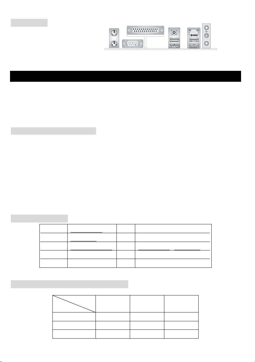
バックパネル
バックパネルには以下のコネクタが用意
されています。
Mouse
Keyboard
COMA
Parallel
SPDIF-Out
USB Port s US B Ports
LAN
(O ptio nal)
L-in
L-out
Mic
ハードウエアセットアップ
この章ではハードウェアのインストール手順について説明します。インストール中は、各種コンポーネン
トの取り扱いおよびインストール手順には最新の注意を払ってください。いくつかのコンポーネントは誤
った方向にインストールすると破損または不安定になる場合があります。
Central Processing Unit: CPU
本製品は Intel® Pentium® 4 プロセッサで動作します。本製品は PGA 478 というソケットを使用しているた
め CPU のインストールが大変簡単です。CPU の過剰な発熱を防ぐためには必ずヒートシンクと冷却ファン
が必要です。もしヒートシンクと冷却ファンが見つからない場合は、販売店に連絡するか、別途購入して
からコンピュータの電源をオンにしてください。
(最新の CPU 対応表は下記のホームページからご参考ください。
http://www.msi.com.tw/program/products/mainboard/mbd/pro_mbd_cpu_support.php )
CPU クロックの設定
例えば CPU クロック
コア/バス比
すると CPU コアスピード
= 200MHz x 12
=2.4 GHz
= 200MHz
= 12
=
CPU クロック
x コア/バス比
メモリスピード / CPU FSB サポート対応表
メモリ
400MHz OK N/A N/A
533MHz OK OK N/A
800MHz N/A OK OK
DDR 266 DDR333 DDR 400
93
Page 98

Socket 478 CPU のインストール手順
1. CPU を装着する前に必ず電源スイッチをオフにし、電源コードを抜いてください。
2. レバーをソケットから横方向に引っ張ってください。そのままレバーを持ち上げるようにしてソケ
ットとの角度が 90 度になるまで開きます。
3. ソケットのピン 1 と CPU の金色の矢印もしくは端が欠けている場所を確認してください。それらを
合わせるようにして CPU をソケットに挿入してください。
4. CPU がしっかりと装着されているのなら、ピンが見えないようになります。CPU が正しく装着され
ない場合、マザーボードに厳重なダメージを与えることになります。
5. CPU を奥まで押して、ソケットにしっかりと嵌めてから、レバーを閉じてください。レバーが完全
に閉じる前に、CPU を押した手を離さないでください。
CPU Fan のインストール手順
プロセッサ技術の進歩によりスピードと性能が上がるにつれて温度管理がますます重要になってきました。
熱を拡散するために CPU の上にヒートシンクとファンを取り付ける必要があります。以下の手順に従って
ヒートシンクとファンを取り付けてください。
1. マザーボード上に CPU とりテンションがあることを確認してください。
2. ヒートシンクをリテンションの上に設置してください。
3. ヒートシンクの上にファンを設置します。ファンを下方向に押して 4 つのクリップがリテンション
の穴にはまるようにしてください。
4. 2 つのレバーを押してファンを固定してください。各レバーはそれぞれ 1 方向にしか押し下げられな
いようになっています。
5. マザーボード上の 3 ピンのファン電源コネクタにファンに付いているファン電源ケーブルを接続し
ます。
MSI Reminds You...
CPU
の過熱…
CPU
が過剰な熱を持つと破損する場合があります。使用される冷却ファンが正常に動作することを必ず
確認してから
CPU
の交換…
CPU
を交換する間は必ず
CPU
の安全を確保してください。
CPU
の取り付けを行ってください。
ATX
電源を切るか、
ATX
電源用ケーブルを接地コンセントから抜いて、まず
94
Page 99

メモリ
本製品には 2.5V DDR DIMM(Double In-Line Memory Module)モジュールを差し込む 184 ピンソケットが 2/3
本あり、ECC なしのメモリーモジュールを最大 2 GB/3GB のメモリ容量をサポートします。DDR DIMM ス
ロット上、DDR266 / DDR333 / DDR400 SDRAM モジュールをインストールすることができます。適
切に作動する為に、少なくとも 1 つの DIMM モジュールをインストールする必要があります。
(最新のメモリモジュール対応表は下記のホームページからご参考ください。
http://www.msi.com.tw/program/products/mainboard/mbd/pro_mbd_trp_list.php )
1. DDR DIMM スロットには
絵に描いてあるような
"VOLT"の切れ込みがあります。こ
のため、DIMM メモリは 1 方向にし
か挿入できません。
2. DIMM メモリーモジュールを DIMM スロットに垂直に差込み、押し込みます。
3. DIMM スロットの両側にあるプラスチッククリップが自動的に固定されます。
NotchVol t
電源
5V
GND
5V
-5V
GND
GND
PS_ON
GND
-12V
3.3V
本製品では、給電システムとして ATX 電源がサポートされています。
電源コネクタをインストールする前に、ボードに損傷が与えられな
20
10
いようにするため、すべてのコンポーネントが適切にインストールされ
ていることを確認してください。
12 V
5V _ SB
PW_OK
GND
5V
5V
GND
3.3V
3. 3V
GND
ATX 20-ピン電源コネクタ: ATX1
このコネクタを使用すると、AT X 電源に接続することができます。ATX 電源へ接続するには、電源のプラ
グが正しい方向に挿入され、ピンが適切に配置されていることを確認します。そして電源をコネクタの奥
まで差し込みます。
ATX 1 2V 電源コネクタ: JPW1
この 12V 電源コネクタは、CPU への電源供給で使用されます。
12 V
4
12 V
GNDGND
132
95
11
1
Page 100

フロッピーディスクコネクタ: FDD1
T
本製品は 360K、720K、1.2M、1.44M 及び 2.88M のフロッピーディスク
ドライブに対応しています。
CD-In コネクタ: CD1
このコネクタは CD-ROM オーディオコネクタと接続します。
12 V
4
12 V
GNDGND
132
S-Bracket コネクタ: JSP1 (コネクタ)
VDD3
2
1
VC C5
SPDFO
SENSOR
SO UT-R
SPDFO
GND
LFE -O U
SOUT-L
GND
12
11
GND
CET- OU T
このコネクタは、デジタル・オーディオ伝送を対象とした SPDIF(Sony & Philips Digital
Interconnect Format)インタフェースへ接続するために使用します。S-Bracket ではデジタ
ルオーディオ出力の SPDIF ジャック(1 つは光学式コネクタ、もう 1 つは同軸式コネク
タ)、及び 4 チャンネルオーディオの 2 つのアナログ出力ジャックが付いています。光
学式 SPDIF ジャックに接続したいとき、プラグを外して使ってください。
ファン電源コネクタ: CPUFAN1/SYSFAN1
+12V
GND
これらのコネクタは+12V の冷却ファンをサポートします。3 ピンコネクタをサポートします。接続すると
きに注意しなければならないのは、赤い線はプラスなので+12V に、黒い線はアースなので GND に接続す
ることです。また、本製品のシステムハードウェアモニタ機能を使用する場合はファン回転数センサー機
能がついたファンを使用する必要があります。
MSI Reminds You...
1.
適切な冷却ファンについては、ベンダーにお問い合わせください。
2. CPUFAN1
Windows
はファンコントローラをサポートしています。
上でファンの回転数を監視することができます。
96
PC Alert
ユーティリティーを使用すると、
 Loading...