

Page 1
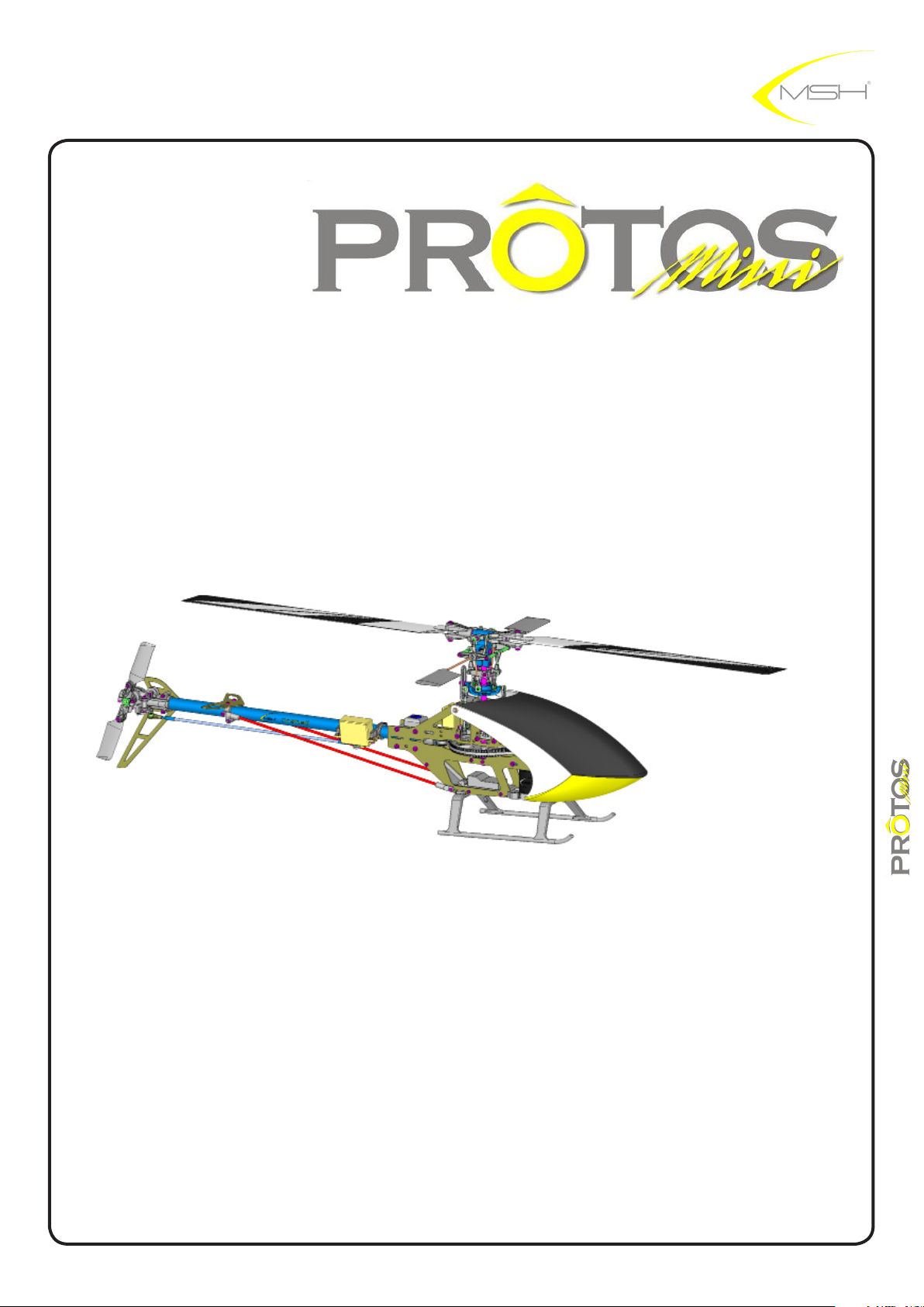
RC helicopter
instructions manual
Main rotor diameter: 736mm
Tail rotor diameter: 157mm
Length without main blades: 714mm
Length with main blades: 879mm
Main blades length: 325mm
Overall height: 233mm
Tail rotor-Main rotor ratio: 4,29
Main pulley: 120T
Weight AUW without battery: 635gr
1
instructions manual
Page 2
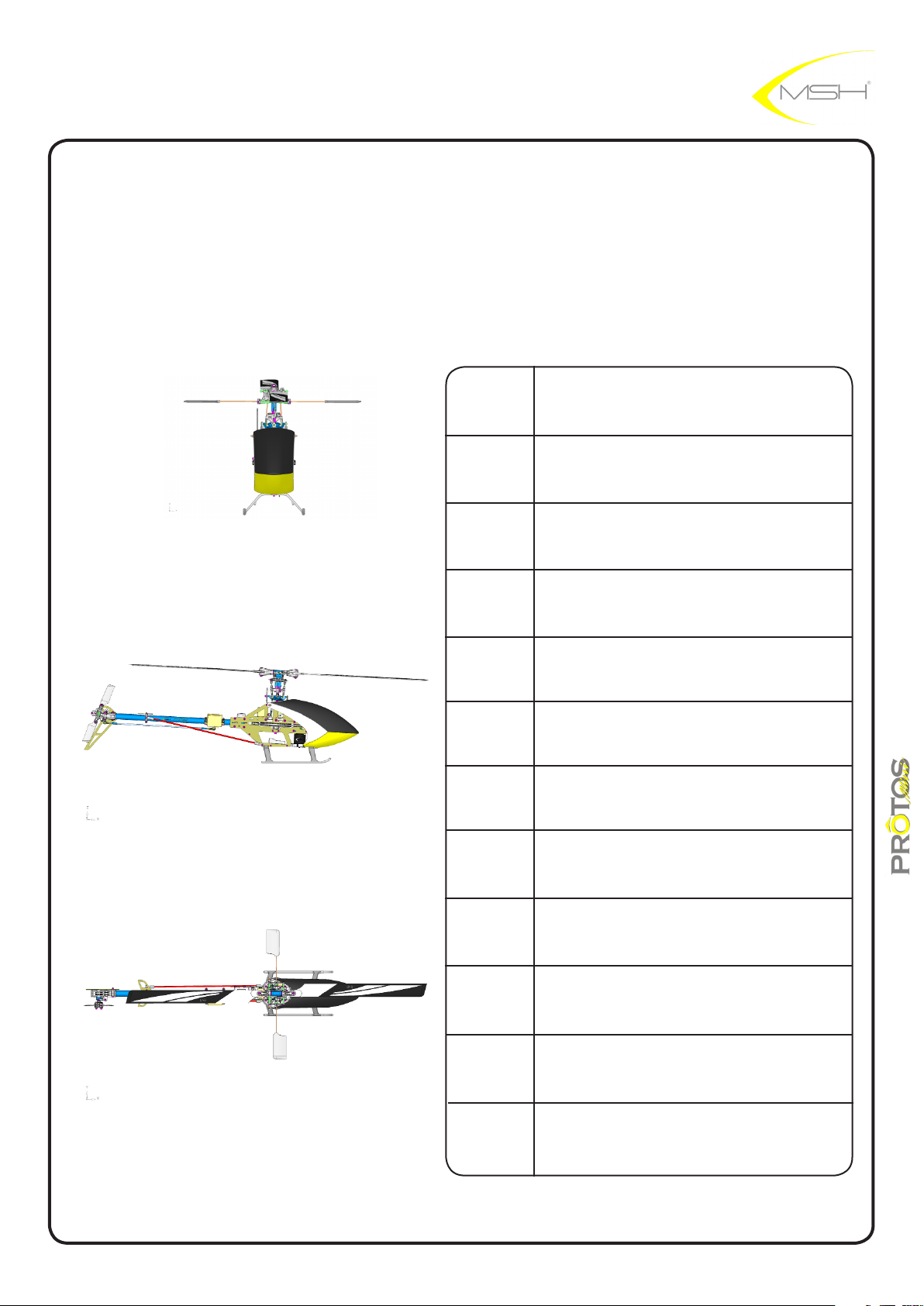
RC helicopter
Instruction Manual
Index
3
4
5
6
7-13
14-22
23-26
safety rules
assembly tools required
R/C equipement required
for assembly
motor pinion teeth choice
main frame assembly
ybarred head assembly
ybarless head assembly
27-37
38-40
41-42
42
43-46
2
tail assembly
motor installation
battery, ESC and canopy
installation
belt tensioning diagram
spare parts listing
instructions manual
Page 3
Always follow these rules for safety
Operate the helicopter in open areas with no people nearby.
Do NOT operate the helicopter in the following places and situations (or else you risk severe
accidents):
-in places where children gather or people pass through
-in residential areas and parks
-indoors and in limited space
-in windy weather or when there is rain, snow, fog or other precipitation
If you do not observe these instructions you may be held reliable for personal injury or property damage!
Always check the R/C system prior to operating your helicopter.
When the R/C system batteries get weaker,the operational range of the R/C system decreases
Note that you may lose control of your model when operating it under such conditions
Keep in mind that other people around you might also be operating a R/C model.
Never use a frequency which someone else is using at the same time.
Radio signals will be mixed and you will lose control of your model
If the model shows irregular behavior, bring the model to a halt immediately and disconnect the batteries.
Investigate the reason and fix the problem.
Do not operate the model again as long as the problem is not solved, as this may lead to further trouble
and unforeseen accidents.
.
.
.
In order to prevent accidents and personal injury, be sure to observe the following:
Before fying the helicopter, ensure that all screws are tightened.
A single loose screw may cause a major accident
Replace all broken or defective parts with new ones, as damaged parts lead to crashes
Never approach a spinning rotor. Keep at least 10 meters/yards away from a spinning rotor blades
Do not touch the motor immediately after use. It may be hot enough to cause burns.
Perform all necessary maintenance.
PRIOR TO ADJUSTING AND OPERATING YOUR MODEL, OBSERVE THE FOLLOWING
Operate the helicopter only outdoors and out of people’s reach as the main rotor operates at high rpm
While adjusting, stand at least 10 meter
Novice R/C helicopter pilots should always seek advice from experienced pilots to obtain hints with assembly
and for pre-fight adjustments.
Note that a badly assembled or insuffciently adjusted helicopter is a safety hazard!
In the beginning, novice R/C helicopter pilots should always be assisted by an experienced pilot
and never fy alone!
MSHeli Srl
Italy
y alone!
s
.
.
.
!
instructions manual
3
Page 4
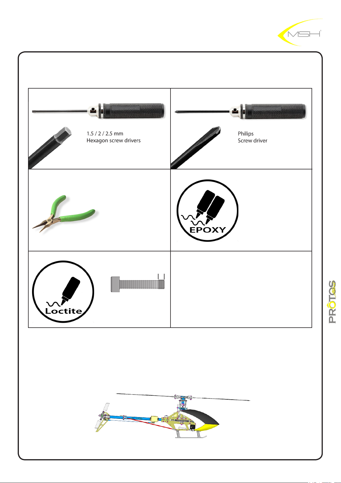
Tools required for assembly
Hex screw driver 1,5-2-2,5 Philips screw driver
Needle nose pliers
where indicated use
read lock MEDIUM (blue)
Slow curing EPOXY
instructions manual
4
Page 5
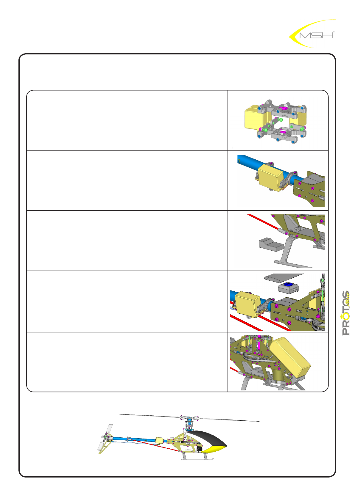
R/C equipement required for assembly
3 micro servos
1 gyro servo micro/mini
1 receiver
1 gyro
1 battery 3S 2000-2500mah
instructions manual
5
Page 6
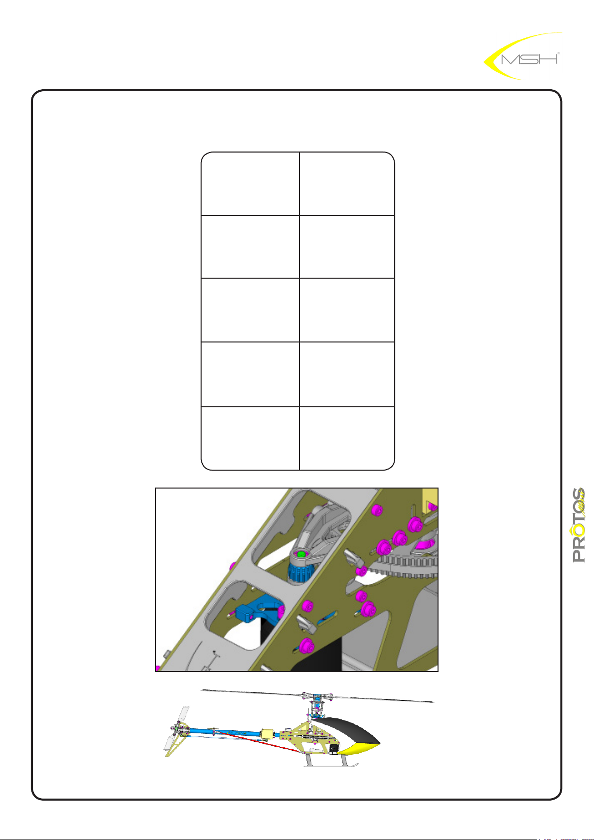
Motor pinion teeth choice
Fly style
Beginner 14-15
Sport 15-16
Soft 3D 16
Hard 3D 17
Battery type
3s
instructions manual
6
Page 7
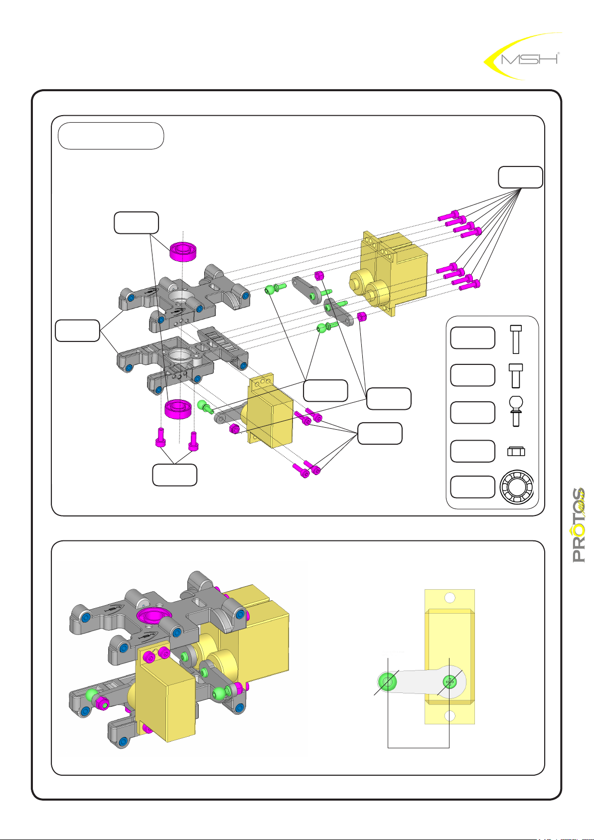
BAG A
BB 6x12x4
MSH40011
servo frame
comolded
MSH40054
hex screw
M2,5x5
MSH50101
ball M2x4,8
MSH50007
M2 nylon nut
MSH40029
hex screw
M2x8
MSH40035
hex screw
M2x8
MSH40035
hex screw
M2,5x5
MSH50101
ball M2x4,8
MSH50007
M2 nylon nut
MSH40029
BB 6x12x4
MSH40011
hex screw
M2x8
MSH40035
15mm
instructions manual
7
Page 8
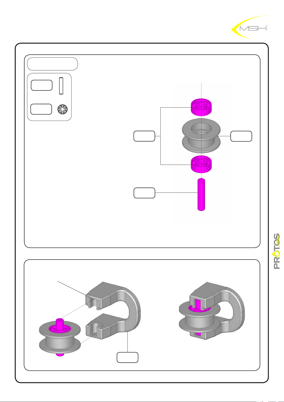
BAG B
pin
2,5x12
BB 2,5x7x2,5
MSH40004
BB 2,5x7x2,5
MSH40004
pin
2,5x12
guide pulley
MSH 40021
CLICK IN POSITION
guide pulley
support
MSH40022
instructions manual
8
Page 9
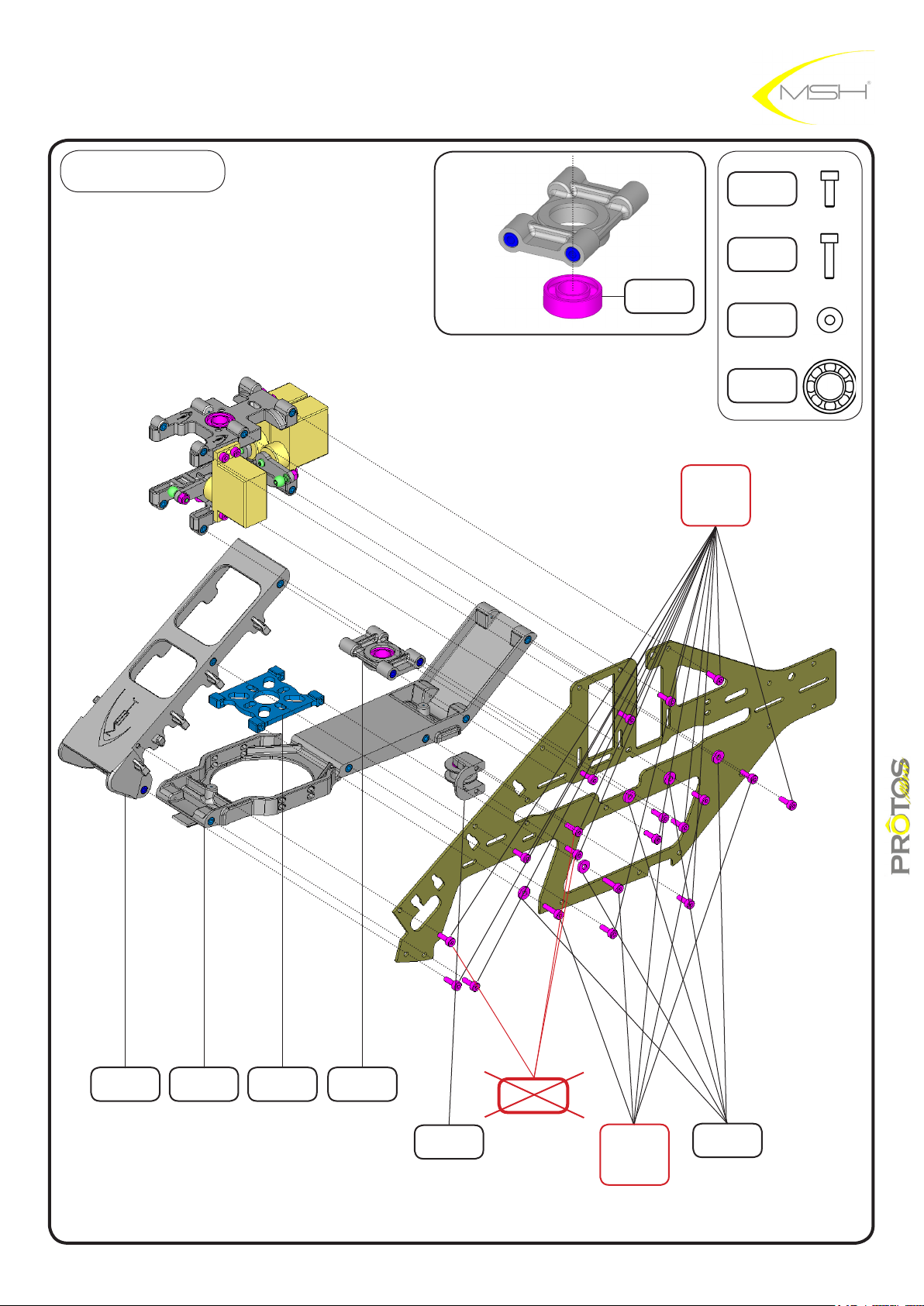
BAG B
BB 6x12x4
MSH400011
LOCTITE
hex screw
M2x6
MSH50098
hex screw
M2x6
MSH50098
hex screw
M2x8
MSH40035
washer
2,1x5,5x1
MSH40085
BB 6x12x4
MSH40011
battery plate
MSH40002
lower plate
MSH40027
motor mount
MSH40045
3° BB support
MSH40079
guide pulley
support
MSH40022
9
LOCTITE
LOCTITE
hex screw
M2x8
MSH40035
washer
2,1x5,5x1
MSH40085
instructions manual
Page 10
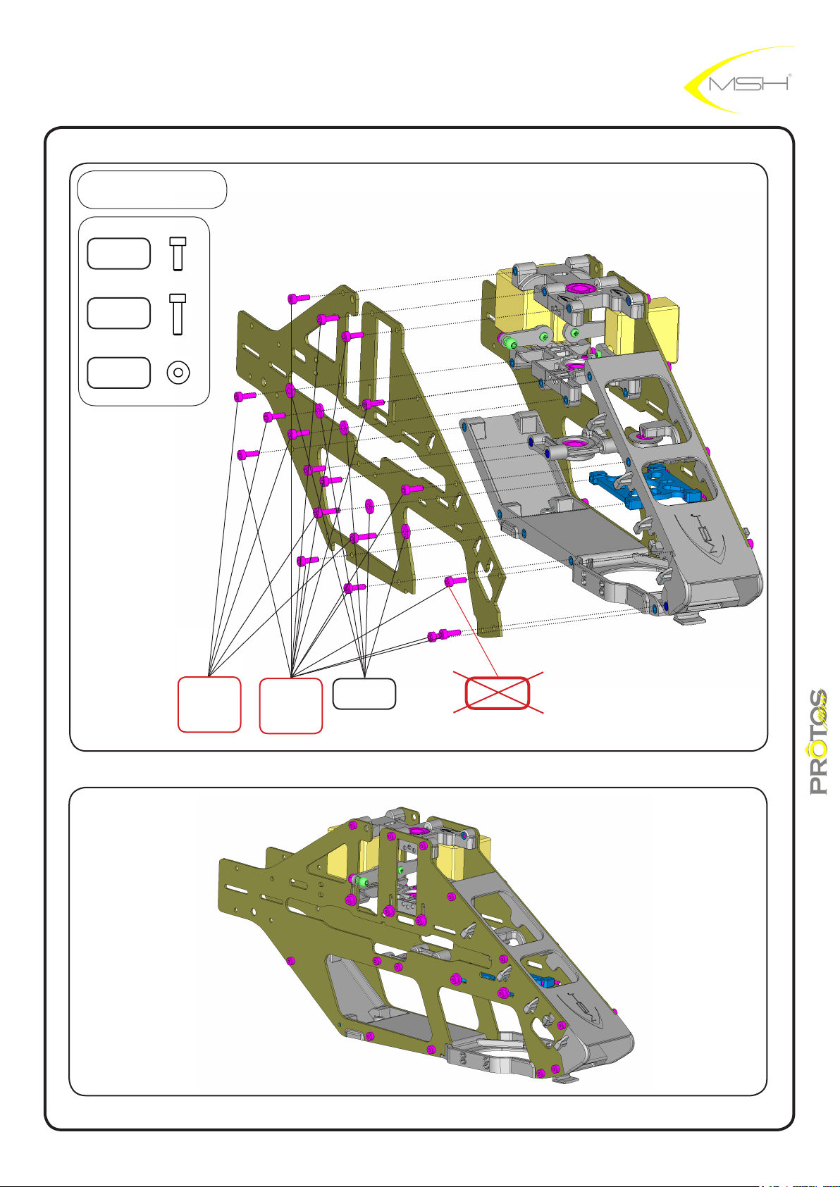
BAG B
hex screw
M2x6
MSH50098
hex screw
M2x8
MSH40035
washer
2,1x5,5x1
MSH40085
LOCTITE
hex screw
M2x8
MSH40035
LOCTITE
hex screw
M2x6
MSH50098
washer
2,1x5,5x1
MSH40085
LOCTITE
10
instructions manual
Page 11
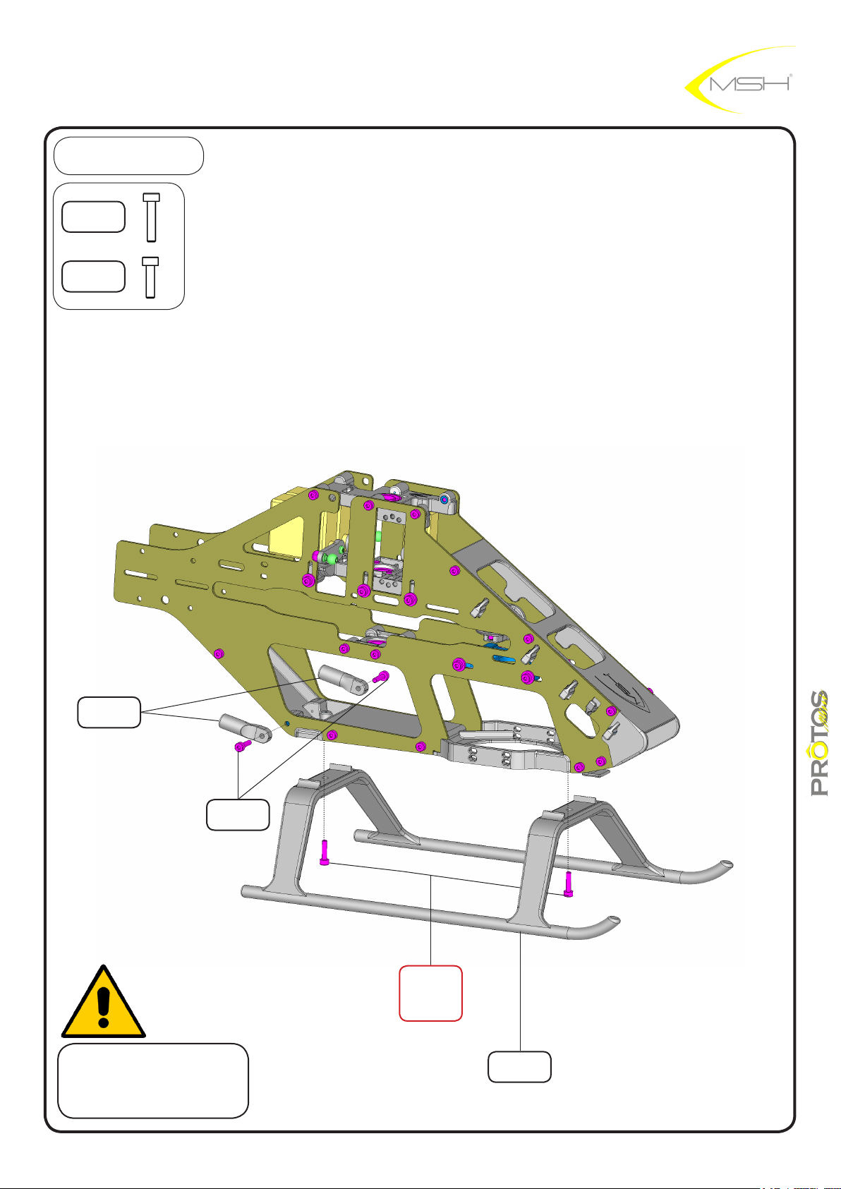
BAG B
hex screw
M2x10
MSH50099
hex screw
M2x8
MSH40035
brace rod end
MSH40014
hex screw
M2x8
MSH40035
do not tighten
brace rod ends screws yet
LOCTITE
hex screw
M2x10
MSH50099
landing gear
MSH50311
11
instructions manual
Page 12
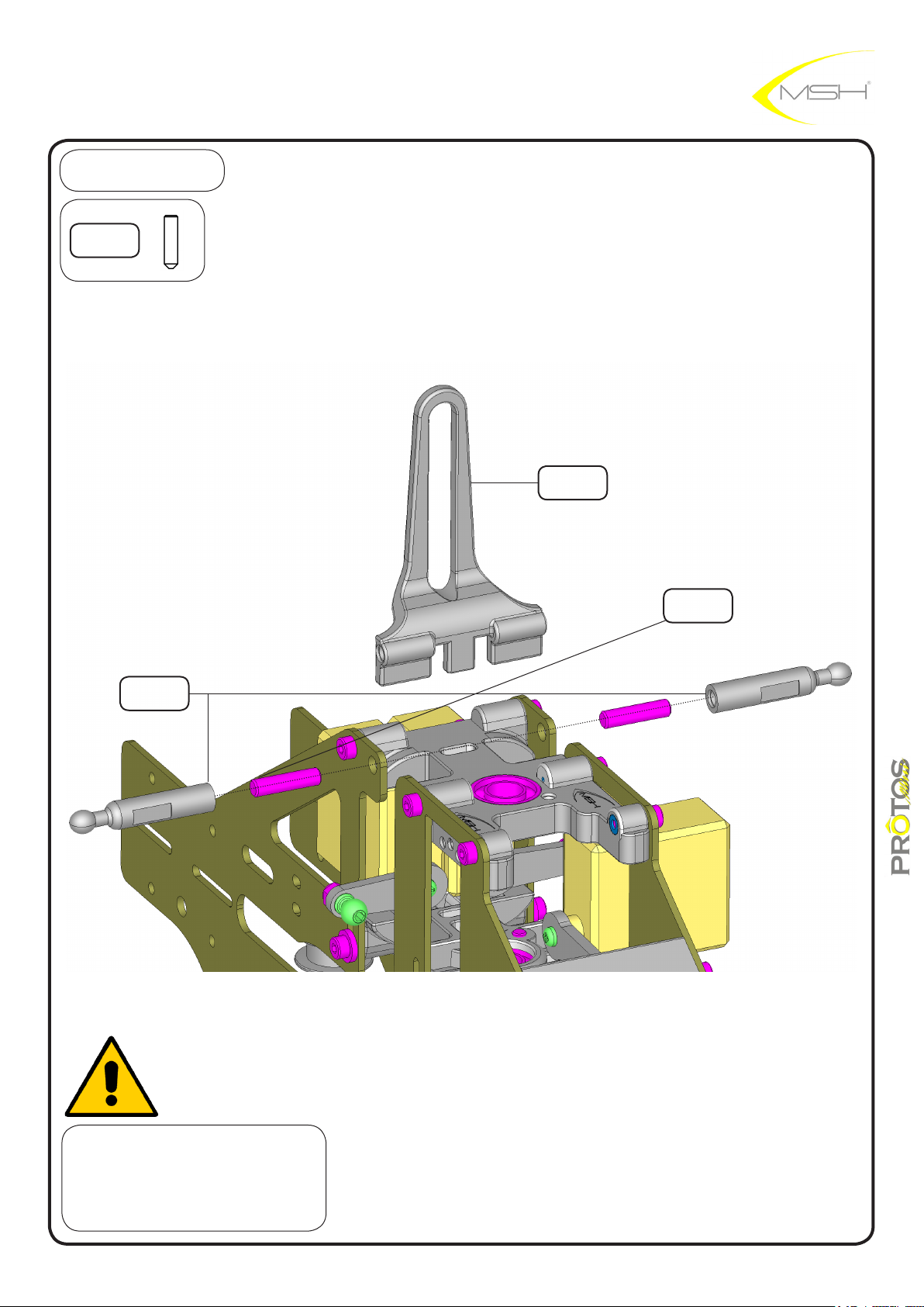
BAG B
hex grub screw
M3x12
MSH40030
anti swashplate
MSH40001
hex grub screw
M3x12
MSH40030
canopy stand
MSH40016
tighten antiswashplate spin
with hex grubscrew M3x12
BEFORE mounting canopy stands
instructions manual
12
Page 13
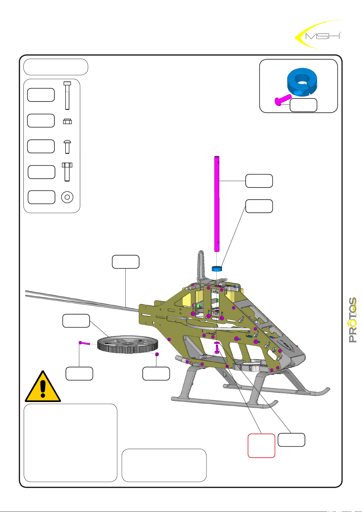
BAG C
hex screw
M2x14
MSH40031
nylon nut M2
MSH40029
hex screw
SPECIAL M2x6
MSH40111
hex head
+screw M2,5x8
MSH40028
washer
2,6x6,5x1,5
MSH50146
main shaft
hollow
MSH40040
main shaft lock
MSH40106
hex screw
SPECIAL M2x6
MSH40111
main pulley
120T
MSH40039
hex screw
M2x14
MSH40031
when tightening shaft collar
check that there in no vertical
play in main shaft assembly.
before sliding main shaft in
position make sure belt is
already in position
belt 2M-1100-4
MSH40013
nylon nut M2
MSH40029
insert main shaft with M2,5
threaded hole facing down
LOCTITE
hex screw
M2,5x8 Ex head
MSH40028
washer
2,6x6,5x1,5
MSH50146
13
instructions manual
Page 14
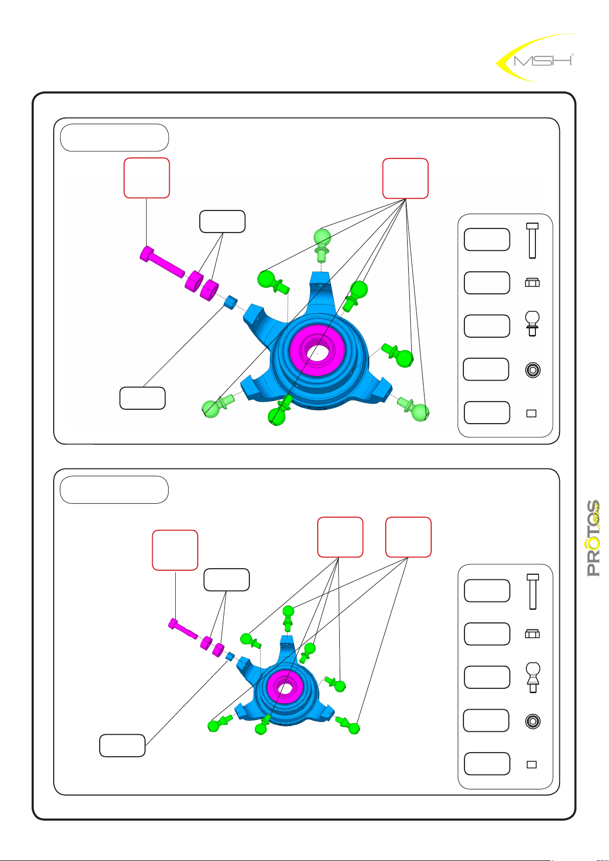
BAG C
swashplate ybarred
LOCTITE
hex screw
M2x10
MSH50099
swashplate
bushing
MSH50021
BB 2x5x2,5
MSH50039
LOCTITE
ball M2x2.8
MSH50009
hex screw
M2x10
MSH50099
nylon nut M2
MSH40029
ball M2x2,8
MSH50009
BB 2x5x2,5
MSH50039
ball M2x2,8
MSH5009
BAG C
swashplate
bushing
MSH50021
LOCTITE
hex screw
M2x10
MSH50099
swashplate ybarless
LOCTITE
ball FBL M2x2.8
MSH50175
hex screw
M2x10
MSH50099
nylon nut M2
MSH40029
ball FBL M2x2,8
MSH50175
BB 2x5x2,5
MSH50039
swashplate
bushing
MSH50021
BB 2x5x2,5
MSH50039
LOCTITE
ball M2x2.8
MSH50009
14
instructions manual
Page 15
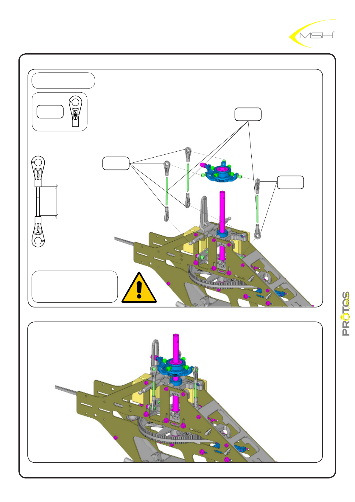
BAG C
uniball hand L
MSH50092
17mm
uniball hand L
MSH50092
rod E 35mm
MSH50045
uniball hand L
MSH50092
check for links smoothness
if tight use provided reamer
15
instructions manual
Page 16
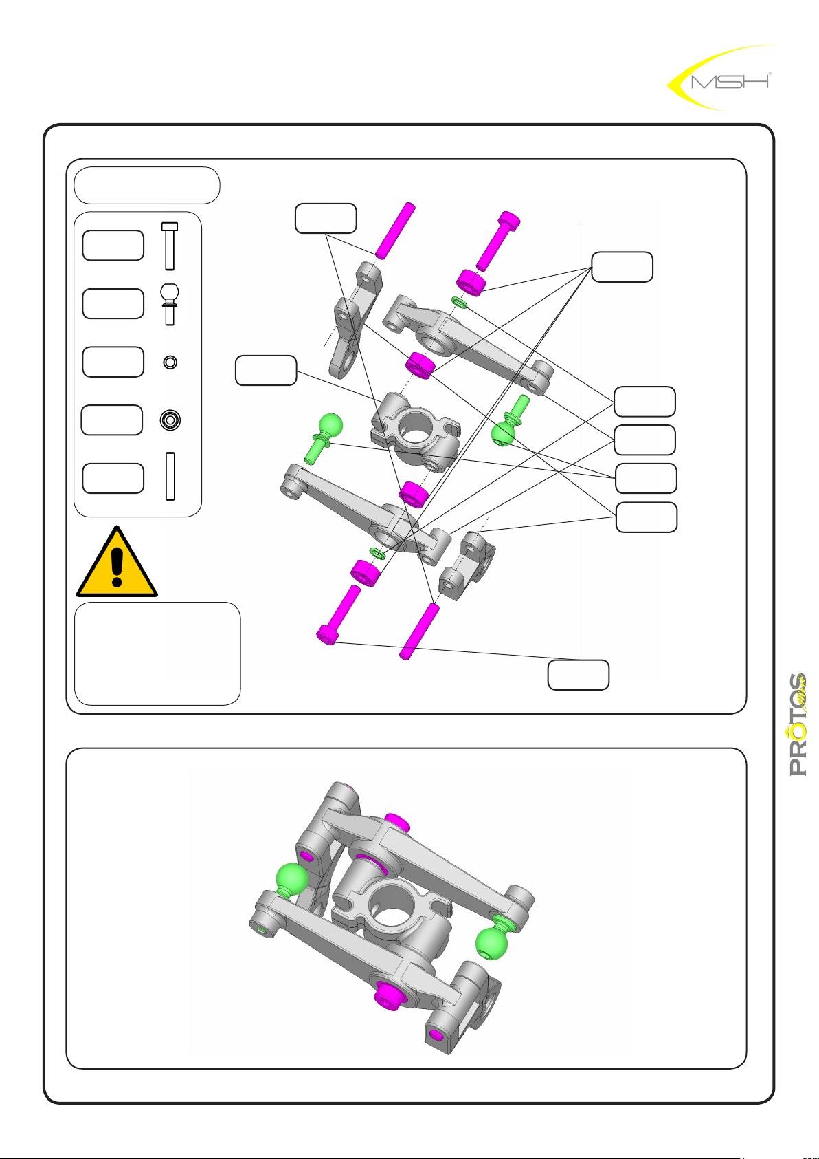
rotor head ybarred
BAG D
hex screw
M2x10
MSH5099
ball M2x4,8
MSH50007
for ybarless rotorhead jump to page 24
pin 2x12 M6
MSH50058
BB 2x5x2,5
MSH50038
bb spacer
MSH40012
BB 2x5x2,5
MSH50039
pin 2x12 M6
MSH50058
check carefully that
BB spacer is in position
between BB before
tightening assembly
washout hub
MSH40083
hex screw
M2x10
MSH5099
bb spacer
MSH40012
washout arm
MSH40082
ball M2x4,8
MSH50007
washout
uniball arm
MSH40084
16
instructions manual
Page 17
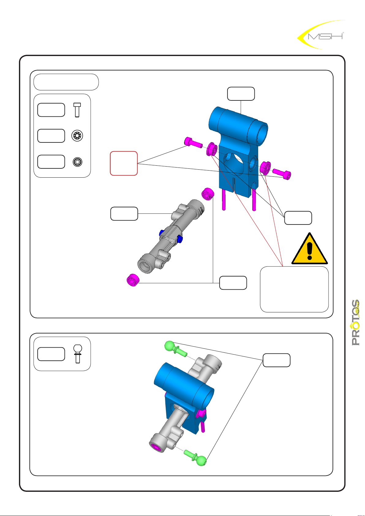
BAG D
hex screw
M2x6
MSH50098
BB 2x5x2,5
anged
MSH50041
main hub
MSH40112
BB 2x5x2,5
MSH50039
LOCTITE
hex screw
M2x6
MSH50098
ybar carrier
MSH 40019
BB 2x5x2,5
MSH50039
BB 2x5x2,5
anged
MSH50041
apply a small amount
of threadlock on the
outside of BB before
sliding it in main hub
ball M2x4,8
MSH50007
17
ball M2x4,8
MSH50007
instructions manual
Page 18
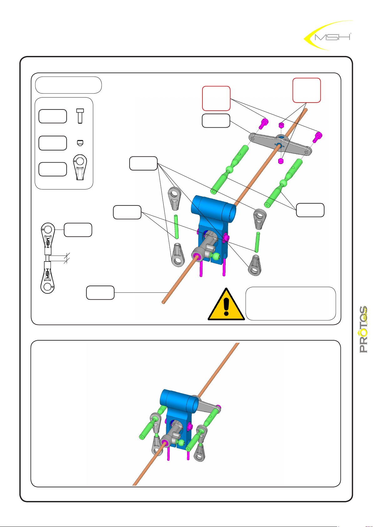
BAG D
hex screw
M2x6
MSH50098
hex grub
screw
M3x3 MSH50117
uniball hand S
MSH50096
uniball hand S
MSH50096
LOCTITE
hex screw
M2x6
MSH50098
ybar arm
MSH40018
LOCTITE
hex grub screw
M3x3
MSH50117
rod 15.1
MSH40050
3,1mm
ybar rod
MSH40020
rod 15,1mm
MSH40050
cross ball
MSH40017
check for links smoothness
if tight use provided reamer
18
instructions manual
Page 19
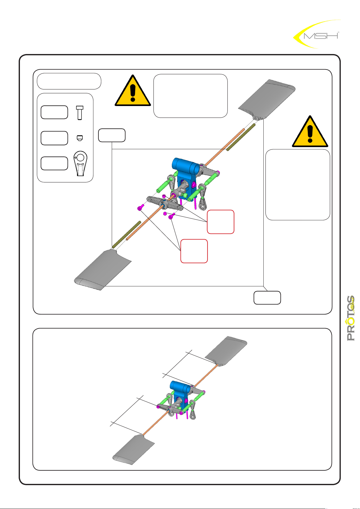
BAG D
hex screw
M2x6
MSH50098
before tightening M3x3
grub screw check for
crossball alignment
hex grub
screw
M3x3 MSH50117
uniball hand S
MSH50096
paddle weight
2,5x50
MSH50062
LOCTITE
hex screw
M2x6
MSH50098
LOCTITE
hex grub screw
M3x3
MSH50117
paddle weights can
be used or not
dependind on ying
style.
for beginners we
advise on using
them
paddle
MSH50088
60,8mm
60,8mm
instructions manual
19
Page 20
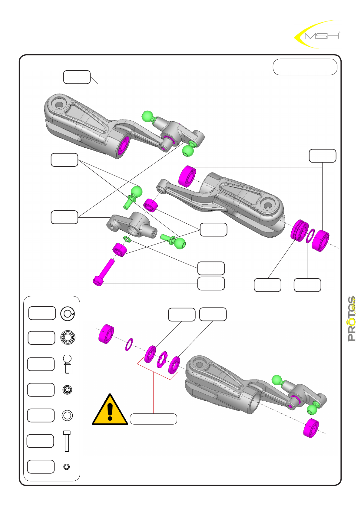
main blade
holder
MSH 40037
BAG D
thrust BB
4x8x2,5
MSH40080
ball M2x4,8
MSH50007
mixer
MSH40041
SMALLER
inside ø
BB 2x5x2,5
MSH50039
bb spacer
MSH40012
hex screw
M2x10
MSH50099
LARGER
inside ø
thrust BB
4x8x2,5
MSH40080
washer
4.1x6x0.2
MSH40087
BB 4x8x3
MSH40008
BB 4x8x3
MSH40008
ball M2x4,8
MSH50007
BB 2x5x2,5
MSH50039
washer
4.1x6x0.2
MSH40087
hex screw
M2x10
MSH50099
bb spacer
MSH40012
apply grease
instructions manual
20
Page 21
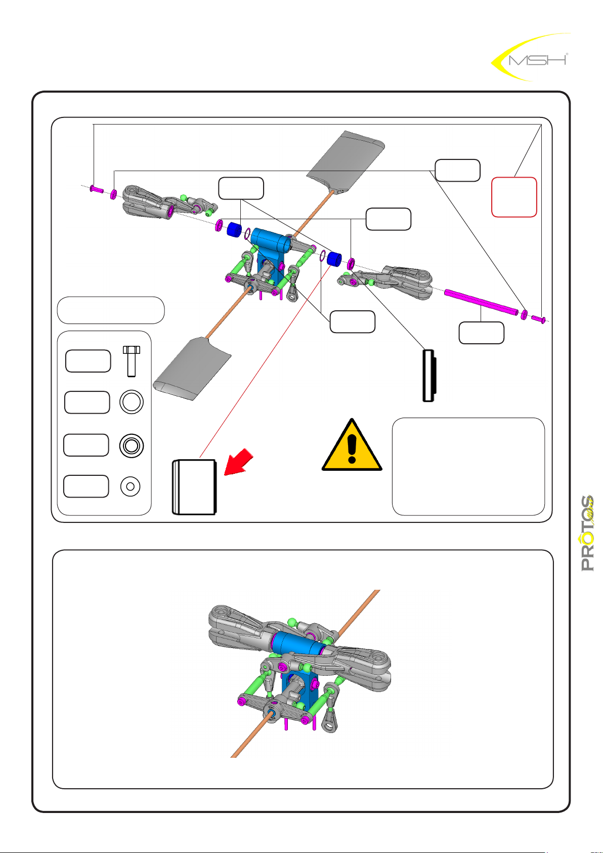
dumper main
head
MSH40105
spindle spacer
MSH40058
washer
2.6x5.6x.0.5
MSH50120
LOCTITE
hex screw
M2.5x8
MSH50103
BAG D
hex screw
M2,5x8
MSH50103
washer
6x8x0.1
MSH40102
spindle spacer
MSH40058
washer
2,6x6,5x1,5
MSH50146
stepped face outside
washer
6x8x0.1
MSH40102
spindle
MSH40057
hub side blade side
apply a thin layer of grase on
the spindle to help it slide in
position.
make sure no grease touches
threaded part of spindle
21
instructions manual
Page 22
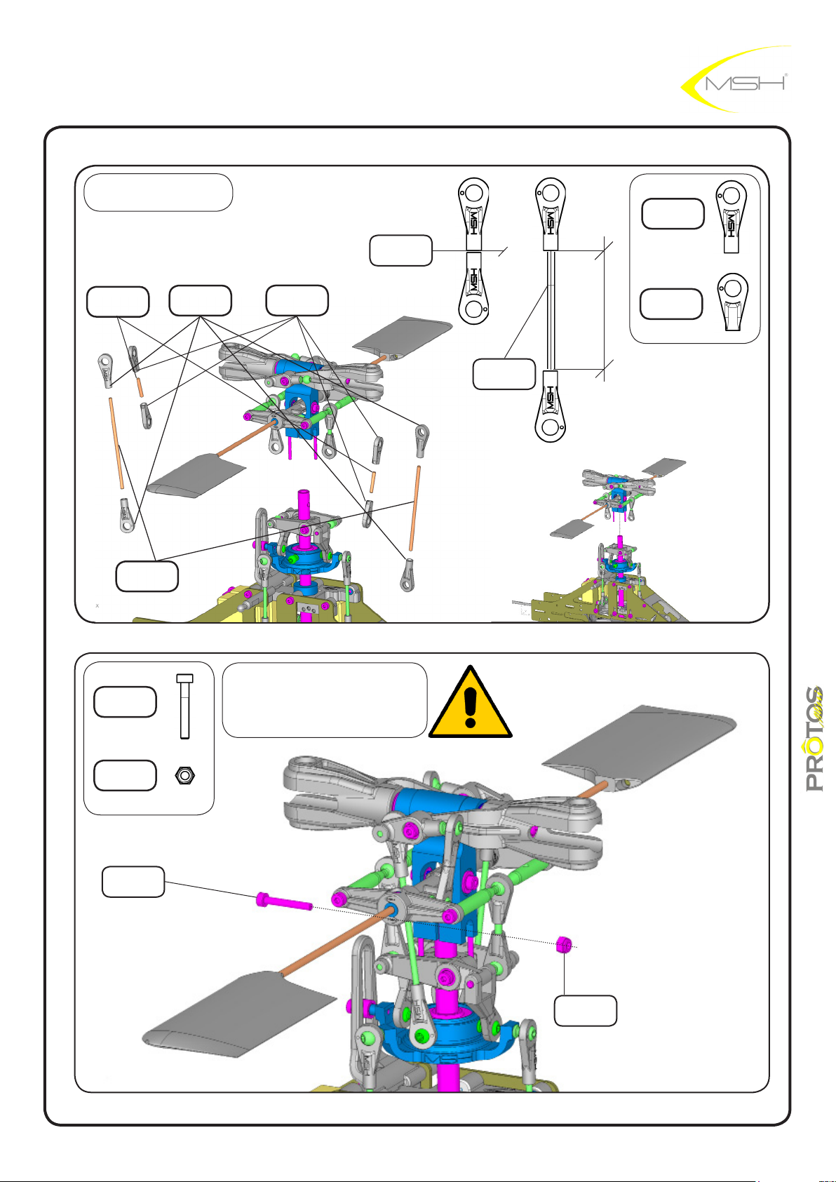
BAG D
rod 12
MSH50049
0mm
uniball hand L
MSH50092
rod 15,1mm
MSH40050
rod 48,8mm
MSH40051
hex screw
M2x14
MSH 40031
uniball hand L
MSH50092
uniball hand S
MSH50096
check for links smoothness
if tight use provided reamer
rod 48.8
MSH40051
uniball hand S
MSH50096
29.8mm
M2 nylon nut
MSH40029
hex screw
M2x14
MSH 40031
22
M2 nylon nut
MSH40029
instructions manual
Page 23
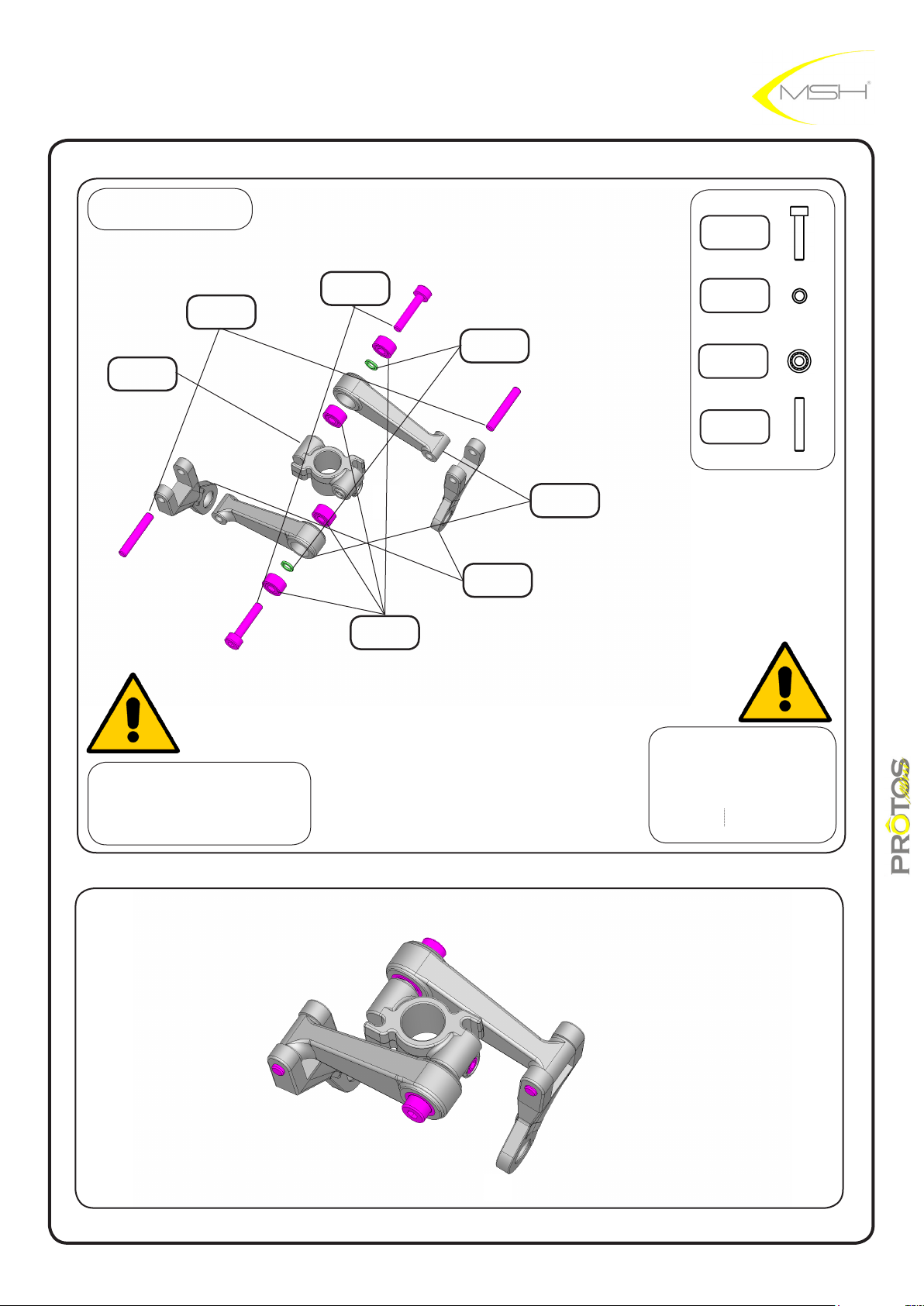
rotor head ybarless
for ybarred rotor head jump to page 16
BAG D
pin 2x12 M6
MSH50058
wash out hub
MSH40083
hex screw
M2x10
MSH50099
BB 2x5x2,5
MSH50039
bb spacer
MSH40012
wash out uni-
ball arm
MSH40084
wash out arm
FBL
MSH41104
hex screw
M2x10
MSH5099
bb spacer
MSH40012
BB 2x5x2,5
MSH50039
pin 2x12 M6
MSH50058
check for links smoothness
if tight use provided reamer
check carefully that
BB spacer is in position
between BB before
tightning assembly
23
instructions manual
Page 24
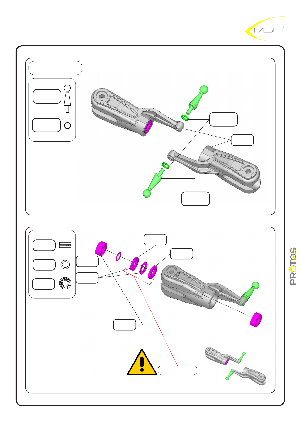
BAG D
ball long stand grips
MSH40107
spindle spacer FBL
MSH40109
ball long stand grips
MSH40107
spindle spacer FBL
MSH40109
main blade
holder
MSH40037
thrust BB
4x8x2,5
MSH40080
washer
4.1x6x0.2
MSH40087
BB 4x8x3
MSH40008
washer
4.1x6x0.2
MSH40087
thrust BB
4x8x2,5
MSH40080
BB 4x8x3
MSH40008
SMALLER
inside ø
LARGER
inside ø
apply grease
24
instructions manual
Page 25
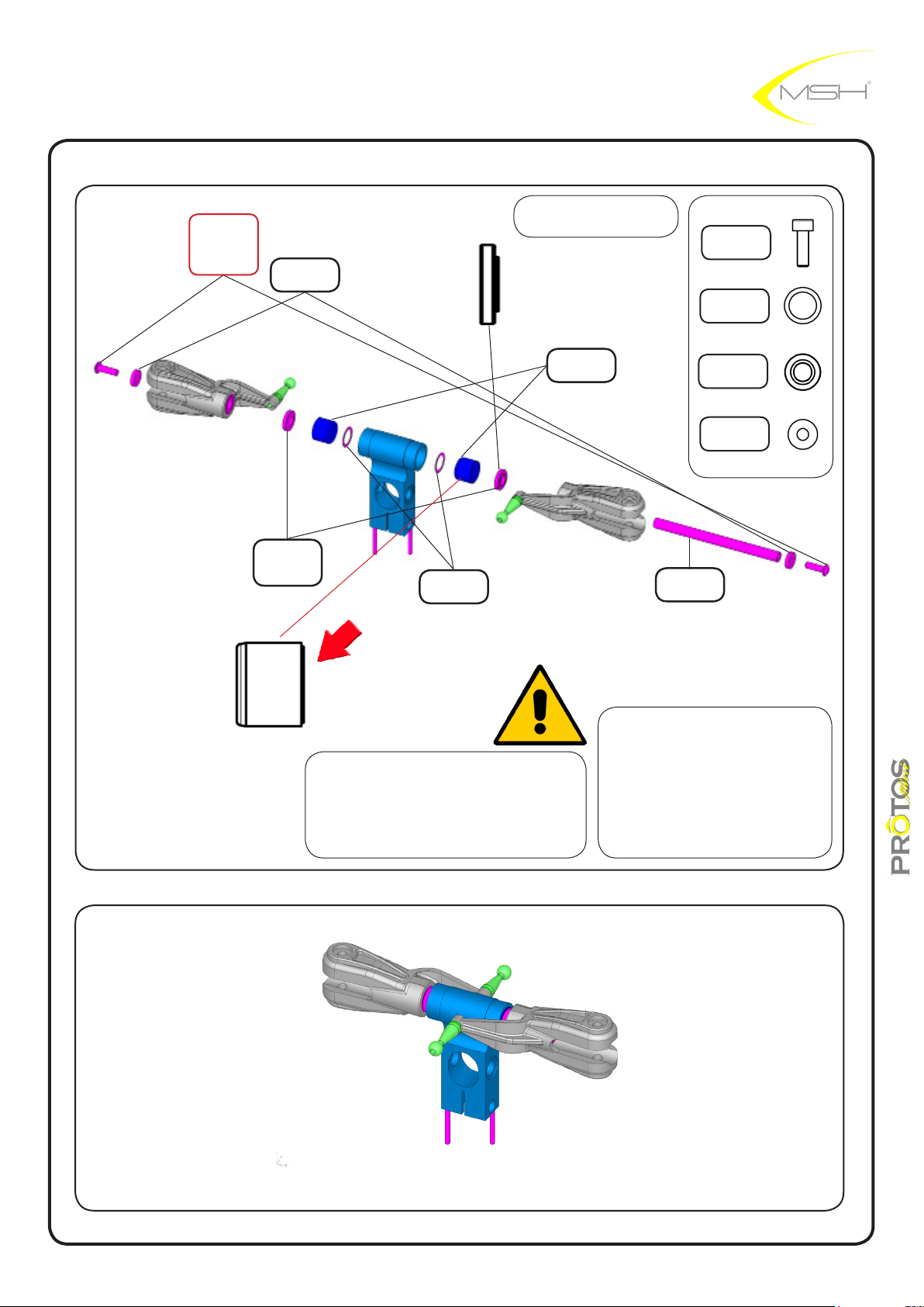
LOCTITE
hex screw
M2.5x8
MSH50103
washer
2.6x5.6x.0.5
MSH50120
spindle spacer
LARGE FBL
MSH40109
BAG D
hub side blade side
dumper main
MSH40105
washer
6x8x0.1
MSH40102
head
MSH50103
MSH40102
spindle spacer
MSH40058
2,6x6,5x1,5
MSH50146
long spindle
FBL
MSH40108
hex screw
M2,5x8
washer
6x8x0.1
washer
stepped face outside
Spindle spacer is a stepped washer,
please make sure that, the stepped
side faces BB 4x8x3.
apply a thin layer of grase on
the spindle to help it sliding
in position.
make sure no grease touches
threaded part of spindle.
25
instructions manual
Page 26
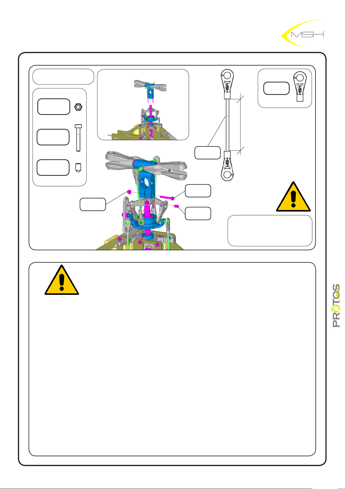
BAG D
M2 nylon nut
MSH40029
uniball hand L
MSH50092
hex screw
M2x14
MSH 40031
hex screw grub M3x5
MSH50116
M2 nylon nut
MSH40029
rod 48.8
MSH40051
hex screw
M2x14
MSH 40031
hex screw grub
M3x5
MSH50116
31.1mm
check for links smoothness
if tight use provided reamer
Slide washout hub all the way up aganist the main rotor head and secure it in position with
provided hex grub screw M3x3.
Do not overtighten grub screw
instructions manual
26
Page 27
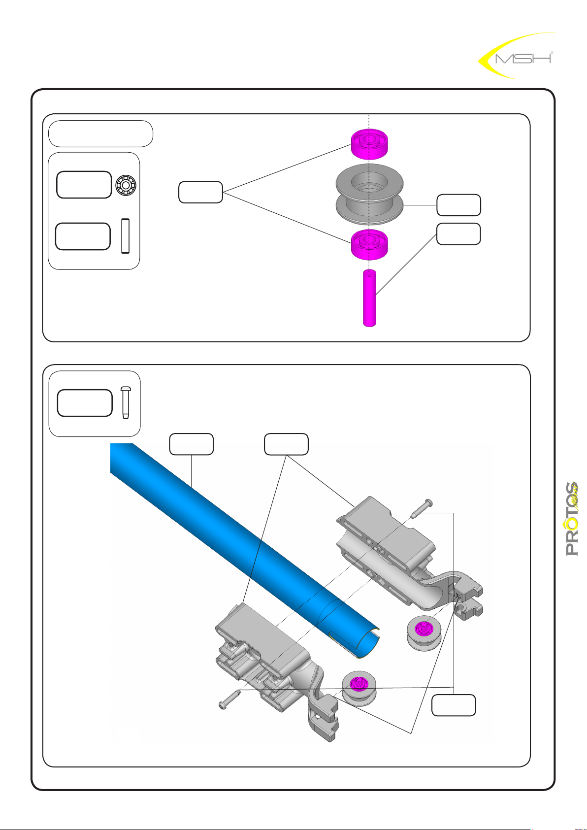
BAG E
BB 2.5x7x2.5
MSH40004
BB 2.5x7x2.5
MSH40004
guide pulley
MSH40021
pin
2,5x12 h6
self tapping screw
2.2x9.5
tail boom
MSH40061
tail boom
clamp
MSH40063
pin
2,5x12 h6
27
self tapping
screw
2.2x9.5
CLICK IN POSITION
instructions manual
Page 28
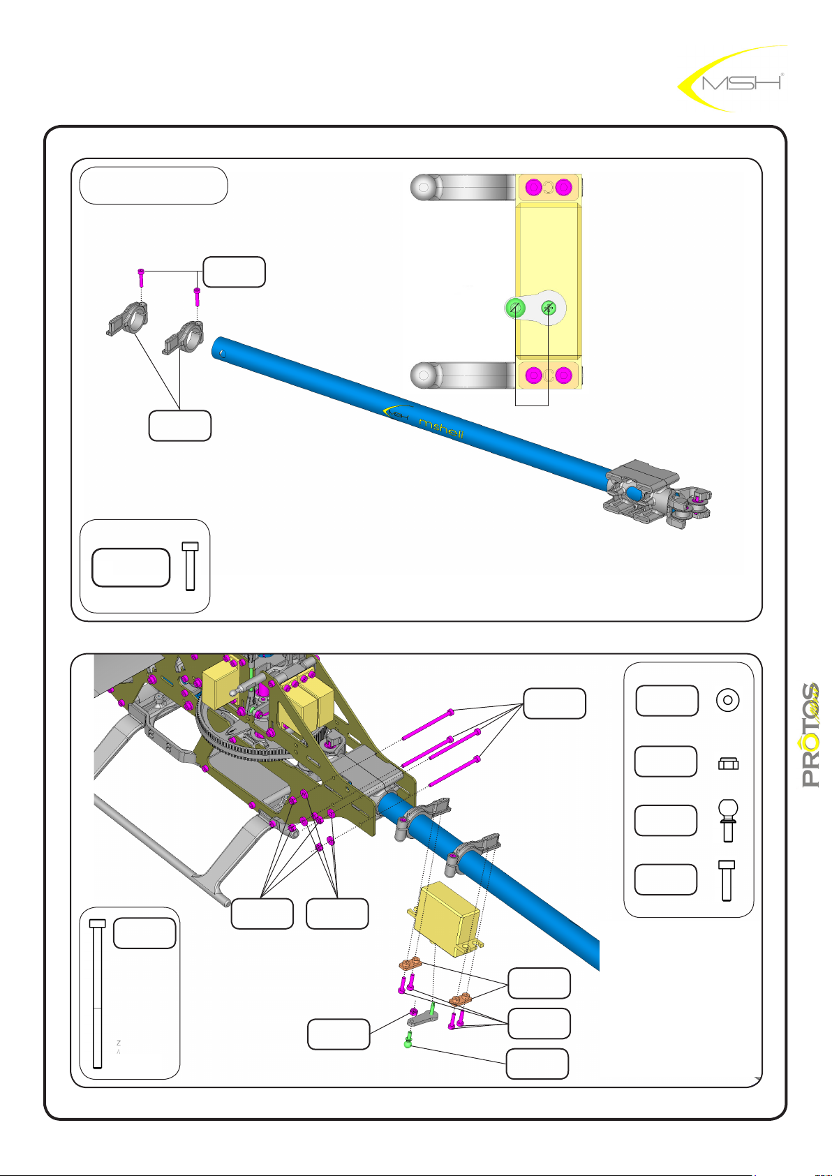
BAG E
hex screw
M2x10
MSH50099
hex screw
M2x10
MSH50099
tail servo
holder
MSH40074
7,5mm
hex screw
MSH40034
M2x36
washer
2,1x5,5x1
M2 nylon nut
MSH40029
ball M2x4,8
MSH50007
hex screw
M2x36
MSH40034
M2 nylon nut
MSH40029
washer
2,1x5,5x1
M2 nylon nut
MSH40029
28
servo adapter
MSH50086
hex screw
M2x8
MSH40035
ball M2x4,8
MSH50007
hex screw
M2x8
MSH40035
instructions manual
Page 29
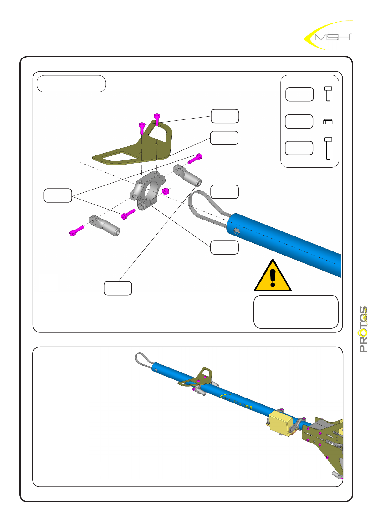
BAG G
hex screw
M2x6
MSH50098
horizontal n cf
MSH40024
hex screw
M2x6
MSH50098
M2 nylon nut
MSH40029
hex screw
M2x10
MSH50099
hex screw
M2x10
MSH50099
brace rod end
MSH40014
M2 nylon nut
MSH40029
horizontal n
clamp
MSH40023
do not tighten M2x10
brace rod ends screws yet
29
instructions manual
Page 30
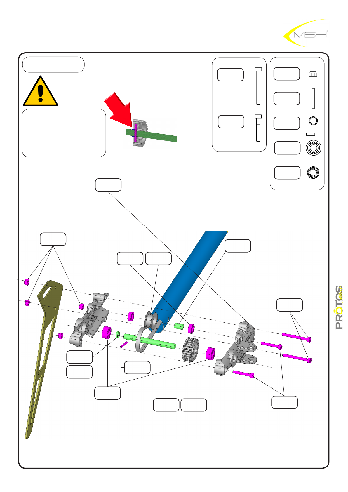
BAG F
hex screw
M2x20
MSH40033
M2 nylon nut
MSH40029
pin 1,5x12 H6
MSH50144
make sure that tail shaft
bushing is halfway inserted
in tail pulley over the pin as
in picture
M2 nylon nut
MSH40029
tail box L/R
MSH40064
MSH40065
BB 4x7x2,5
MSH40007
guide pulley
MSH40021
hex screw
M2x14
MSH40031
tail guide
pulley bushing
MSH40068
tail shaft
bushing
MSH40076
BB 4x9x4
MSH40009
BB 4x7x2,5
MSH40007
tail shaft
bushing
MSH40076
vertical n CF
MSH40081
BB 4x9x4
MSH40009
pin 1,5x12 H6
MSH50144
tail shaft
MSH40075
tail pulley
MSH40073
hex screw
M2x20
MSH40033
hex screw
M2x14
MSH40031
instructions manual
30
Page 31
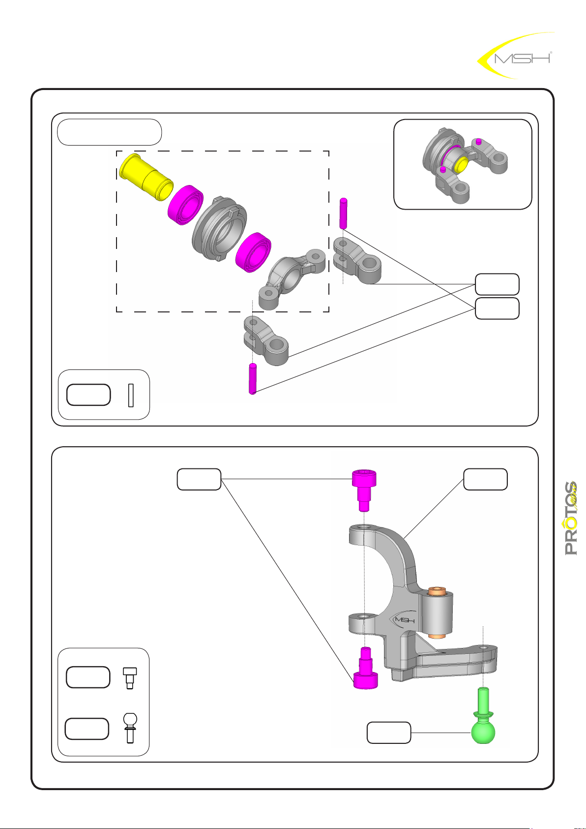
BAG F
preassembled
pin 1,5x8
MSH50057
tail plastic rod
MSH40078
pin 1,5x8
MSH50057
special tail
pitch lever screw
MSH50100
ball M2x4,8
MSH50007
special tail
pitch lever screw
MSH50100
ball M2x4,8
MSH50007
tail pitch lever
MSH40070
31
instructions manual
Page 32
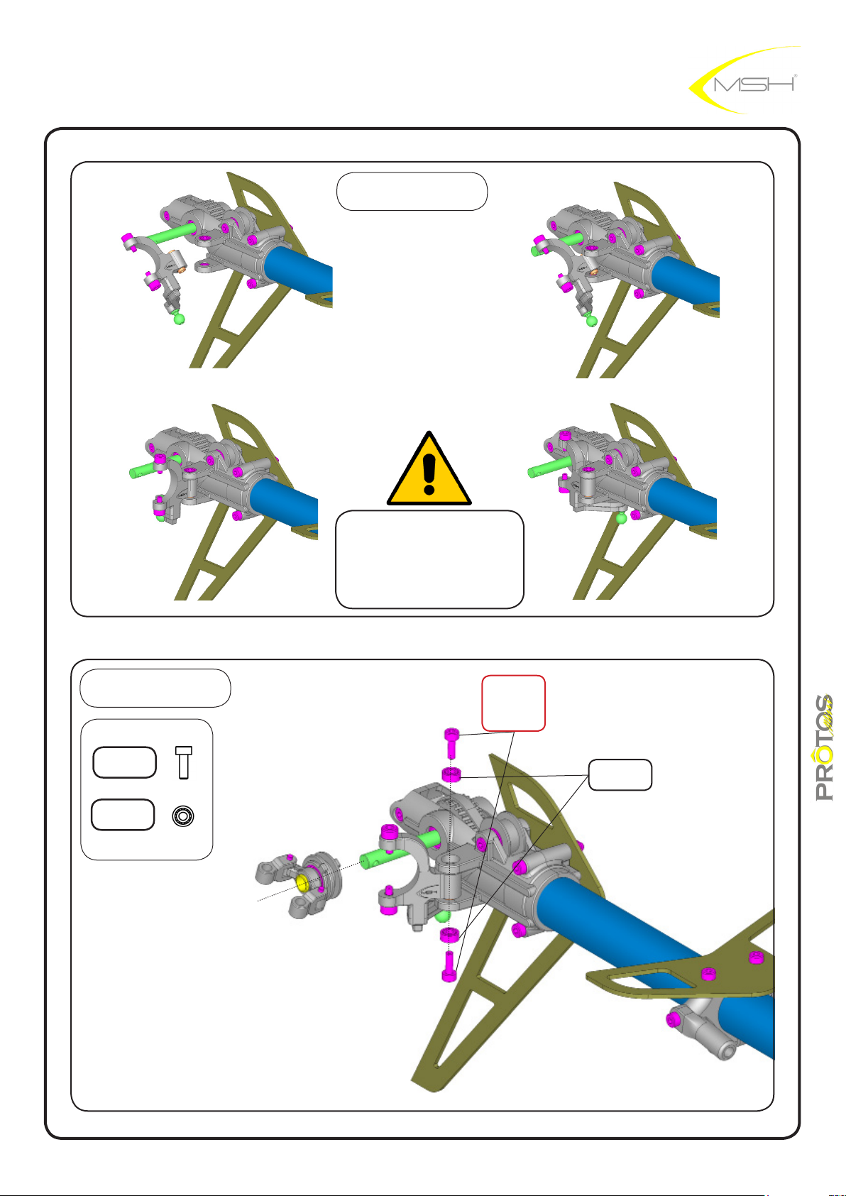
1 2
BAG F
3 4
follow steps in pics
carefully to insert lever in
position
BAG F
hex screw
M2x6
MSH50098
BB 2x5x2
MSH40005
LOCTITE
hex screw M2x6
MSH50098
BB 2x5x2
MSH40005
32
instructions manual
Page 33
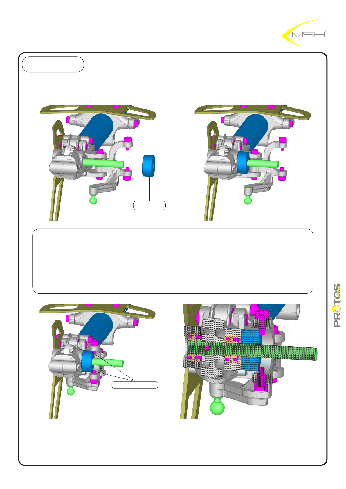
BAG F
1 2
spacer A
Insert spacer A on tail shaft and slide it to the left aganist the tail box. Turn the tail pitch lever
untill tail pitch lever special screws touch the spacer A. Check that both screws touch the
spacer at the same time.
If one screw touches before gently twist the lever untill they touch together.
Warming up lever makes job easier.
Remeber to remove spacer A after the job is completed.
contact point
3
4
instructions manual
33
Page 34
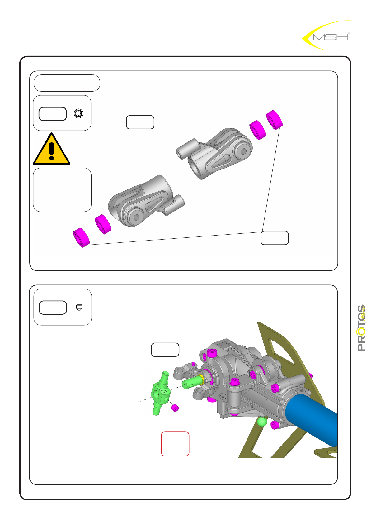
BAG F
BB 3x6x2,5
MSH50037
make sure BB are
fully seated inside
tail blade grip
tail blade
holder
MSH40060
BB 3x6x2,5
MSH50037
hex screw
grub M3x3
MSH50117
tail spindle
MSH40060
LOCTITE
hex grub screw
MSH50117
M3x3
34
instructions manual
Page 35
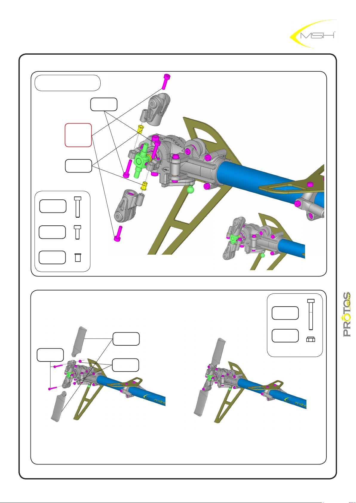
BAG F
LOCTITE
hex screw M2x6
MSH50098
tail pitch
bushing
MSH40069
hex screw
M2x10
MSH50099
hex screw
M2x6
MSH50098
tail pitch
bushing
MSH40069
hex screw
M2x10
MSH50099
hex screw
M2x16
MSH40032
tail blade black
MSH50305
M2 nylon nut
MSH40029
hex screw
M2x10
MSH50099
M2 nylon nut
MSH40029
instructions manual
35
Page 36
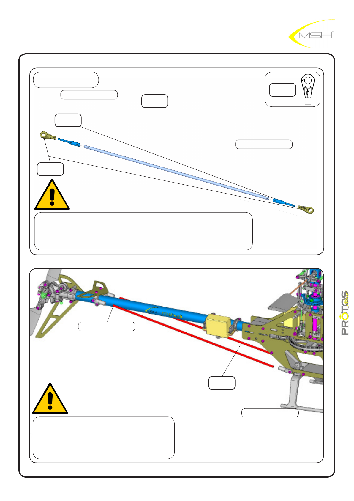
BAG L
slow curing epoxy
tail control rod
tting
MSH40066
uniball hand L
MSH50092
gently remove coating with sandpaper on 10mm a the end of
control rod and boom brace.
tail control
rod CF
MSH40067
slow curing epoxy
uniball hand L
MSH50092
slow curing epoxy
after the braces are in position with epoxy
tighten the 4 screw at the brace rod ends.
remember apply threadlock on the front ones.
36
tail boom
brace CF
MSH40062
slow curing epoxy
instructions manual
Page 37
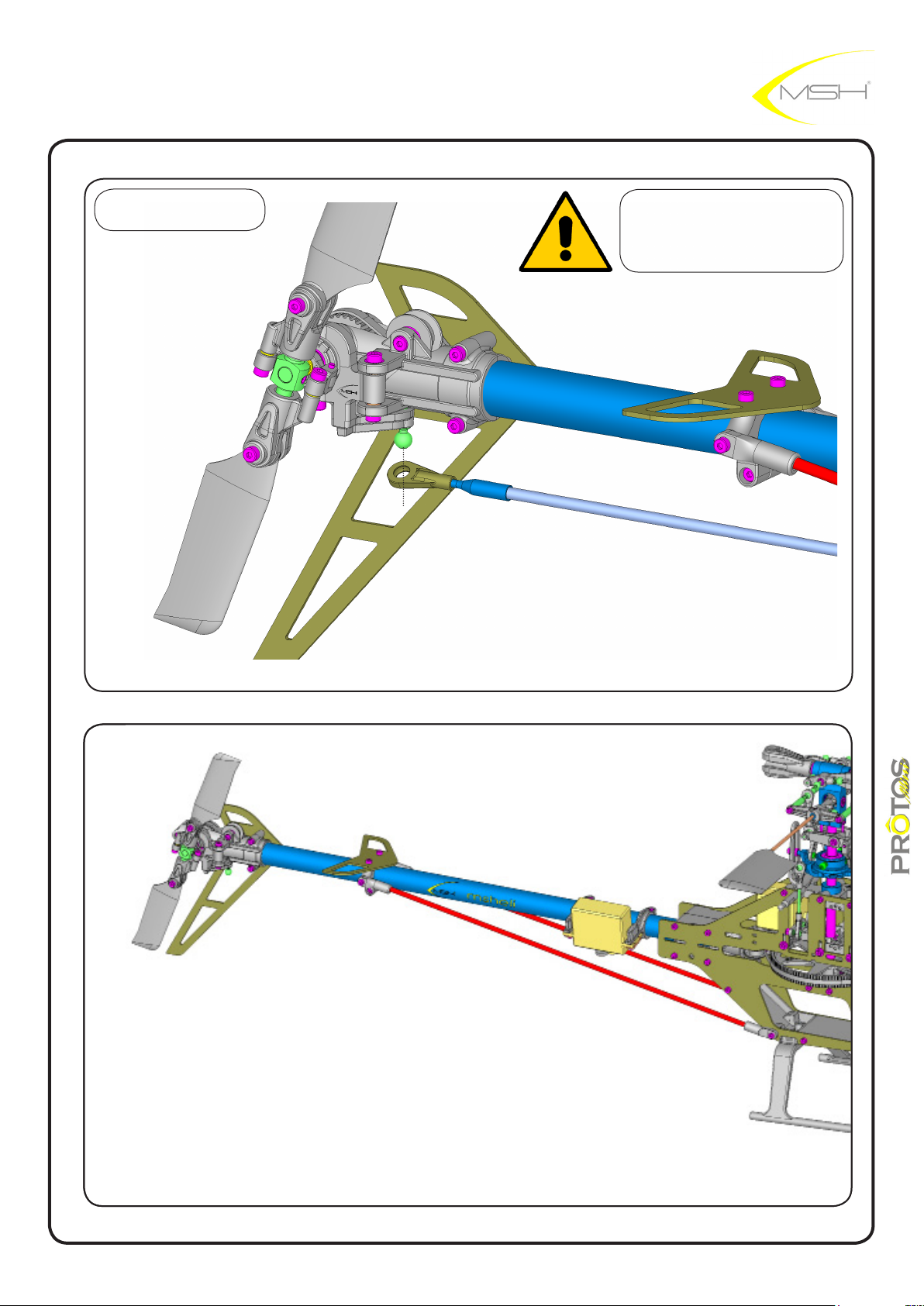
BAG H
check for links smoothness
if tight use provided reamer
37
instructions manual
Page 38
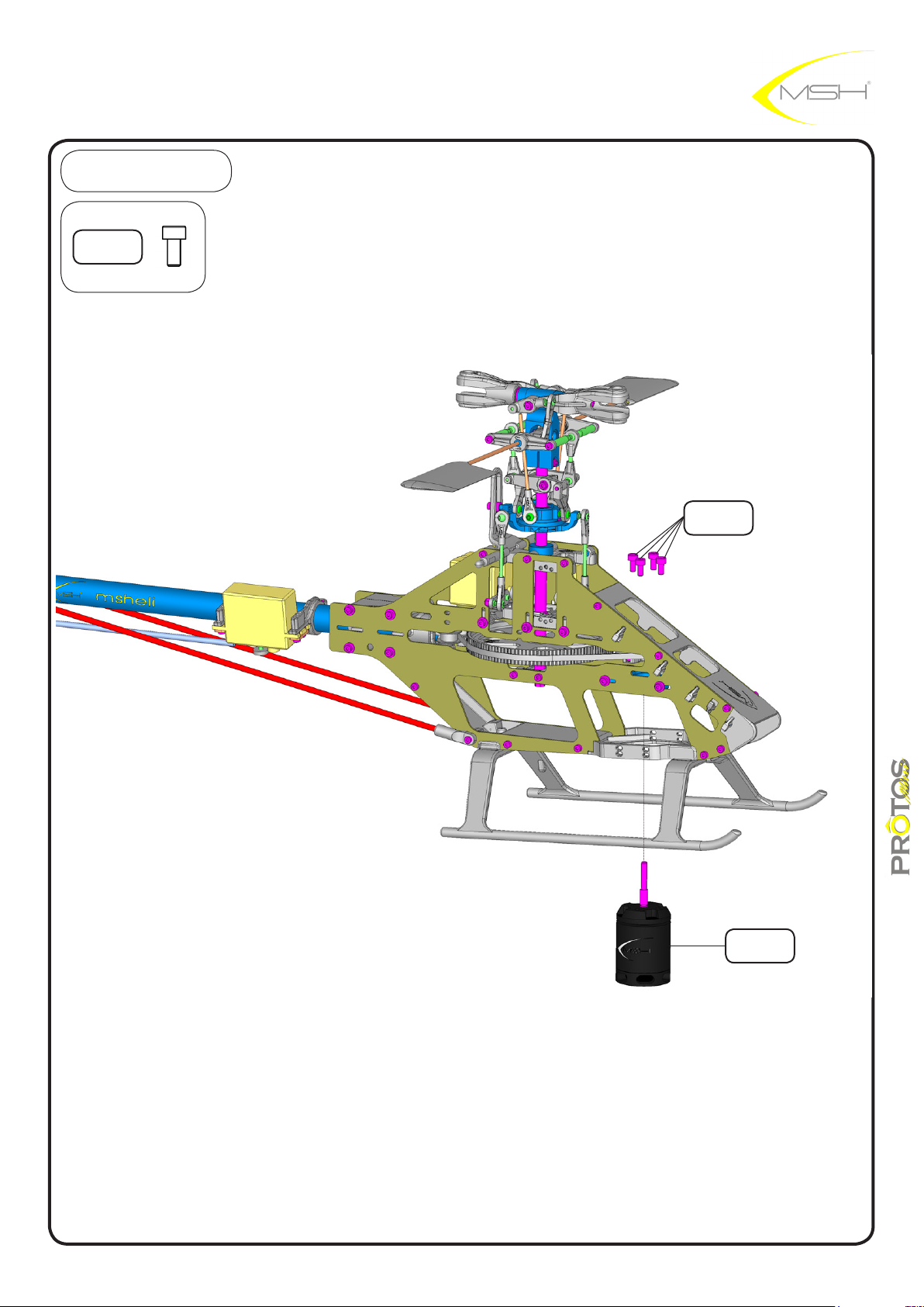
BAG H
hex screw
M3x6
MSH40097
hex screw
M3x6
MSH40097
38
MSH-scorpion
2580KV
MSH40043
instructions manual
Page 39
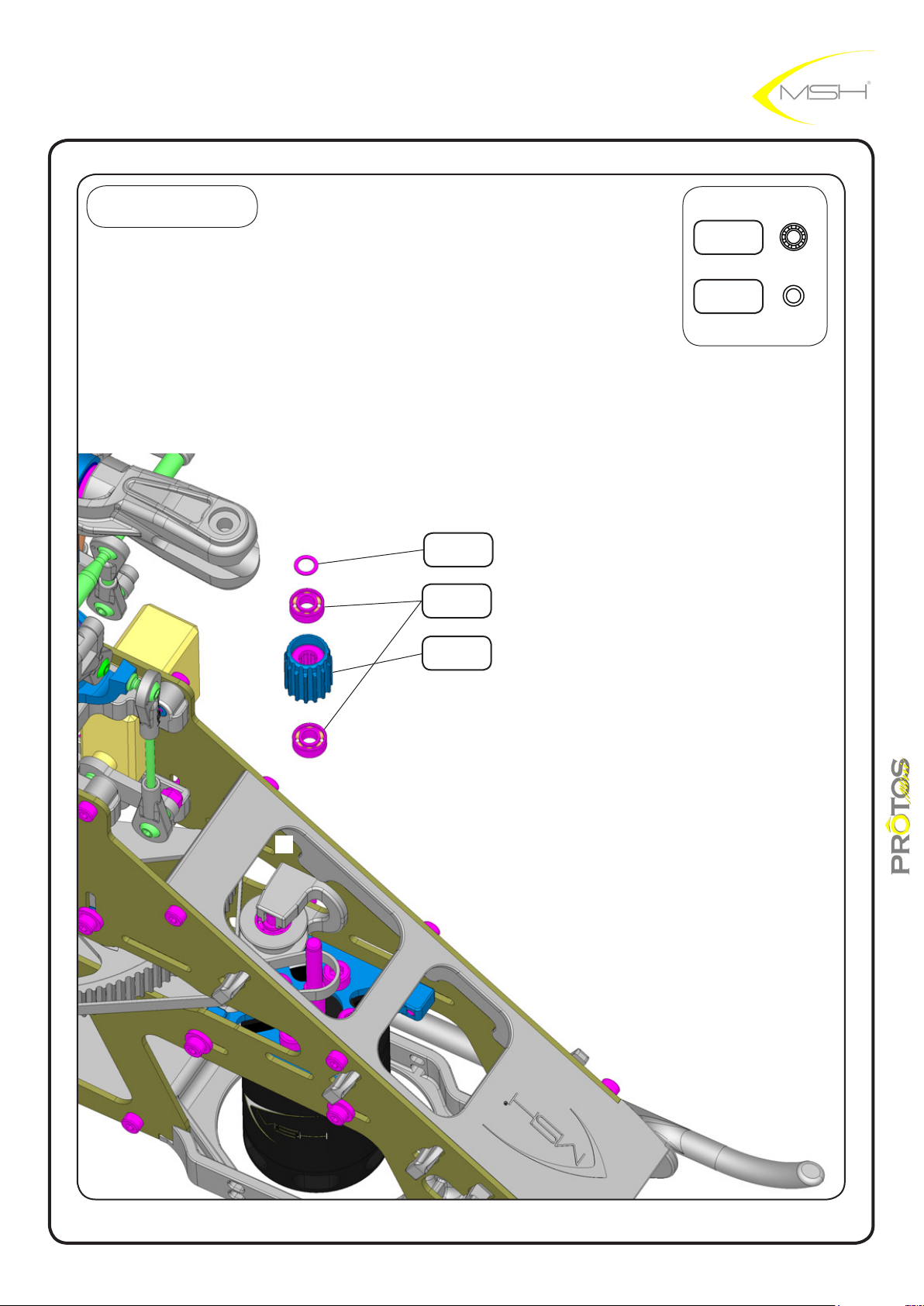
BAG H
washer
3,1x4,5x0,2
MSH40086
BB 3x6,5x2,5
MSH40006
motor pulley
16T
MSH40094
BB 3x6,5x2,5
MSH40006
washer
3,1x4,5x0,2
MSH40086
39
instructions manual
Page 40
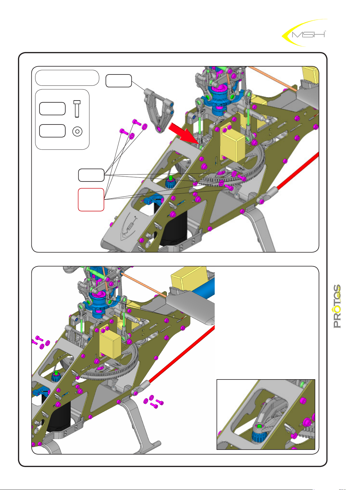
BAG F
hex screw
M2x8
MSH40035
washer
3,1x4,5x0,2
MSH40086
MSH40085
LOCTITE
hex screw
MSH40035
washer
2,1x5,5x1
M2x8
Y support
MSH40103
40
instructions manual
Page 41
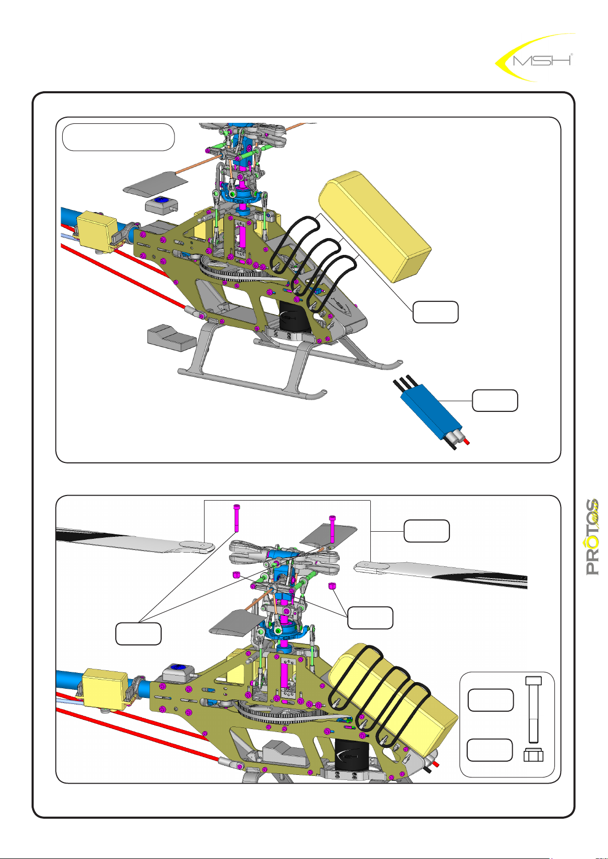
BAG M
battery oring
MSH50053
ESC YGE by
MSH 60A
MSH40088
hex screw
M3x20
MSH50113
M3 nylon nut
MSH50125
SAB blade
325mm
MSH40052
hex screw
M3x20
MSH50113
M3 nylon nut
MSH50125
instructions manual
41
Page 42
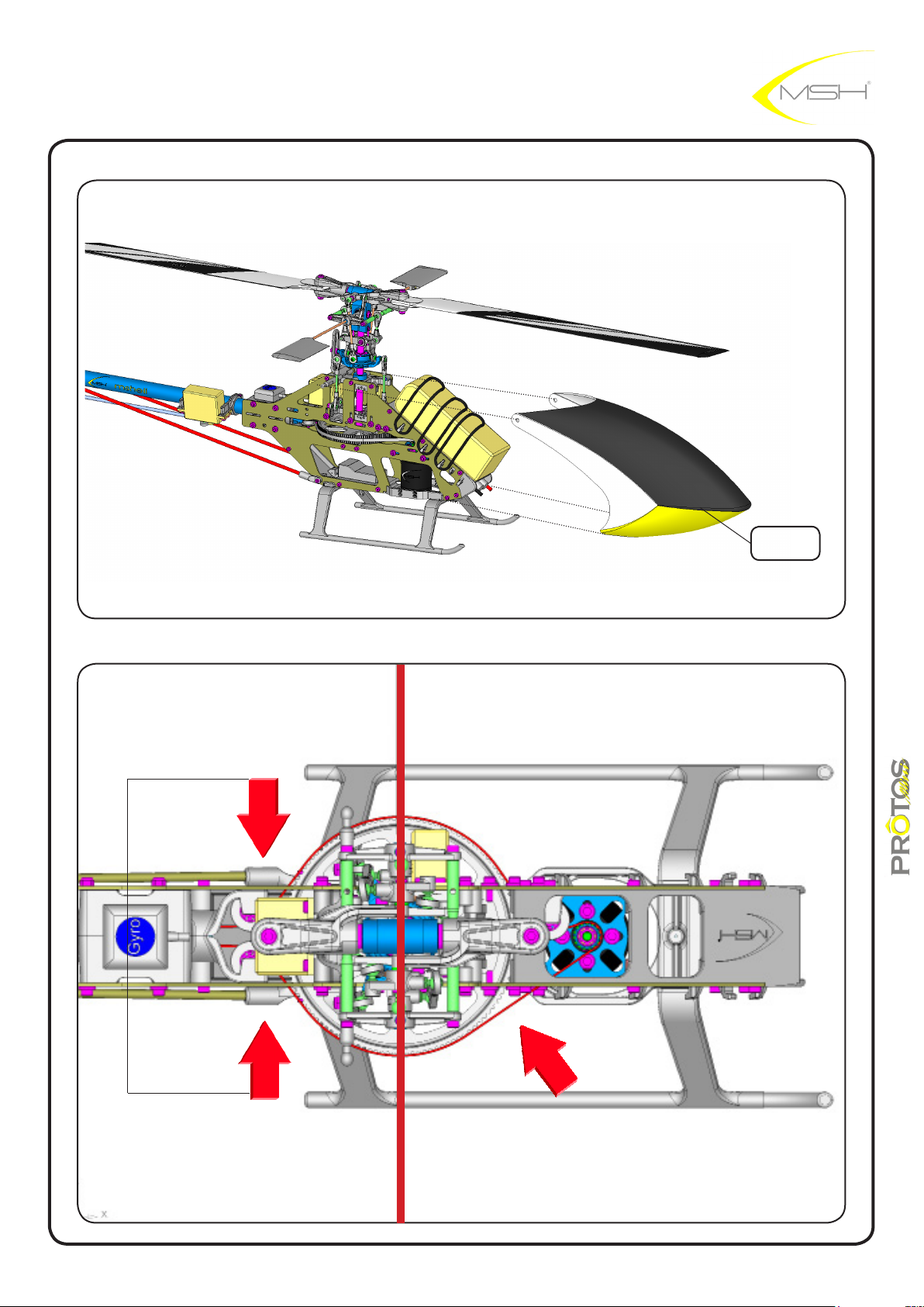
belt tension
check point
belt tension adjustment
Pressing the belt moderately, it should move 2-3 mm.
Test tension as indicated in the picture.
canopy
PROTOS MINI
MSH40015
belt tension
check point
belt tension
check point
REAR TENSION ADJUSTMENT FRONT TENSION ADJUSTMENT
Please make sure that belt tension is set properly on
both sides.
Front and Rear tension is set independently !!
42
instructions manual
Page 43
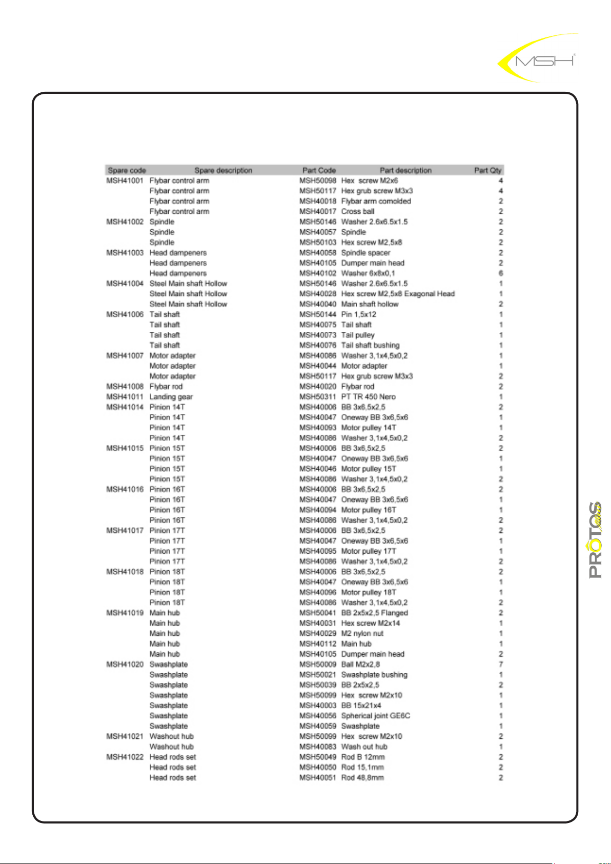
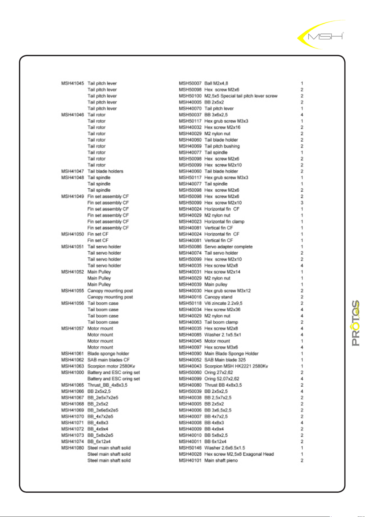
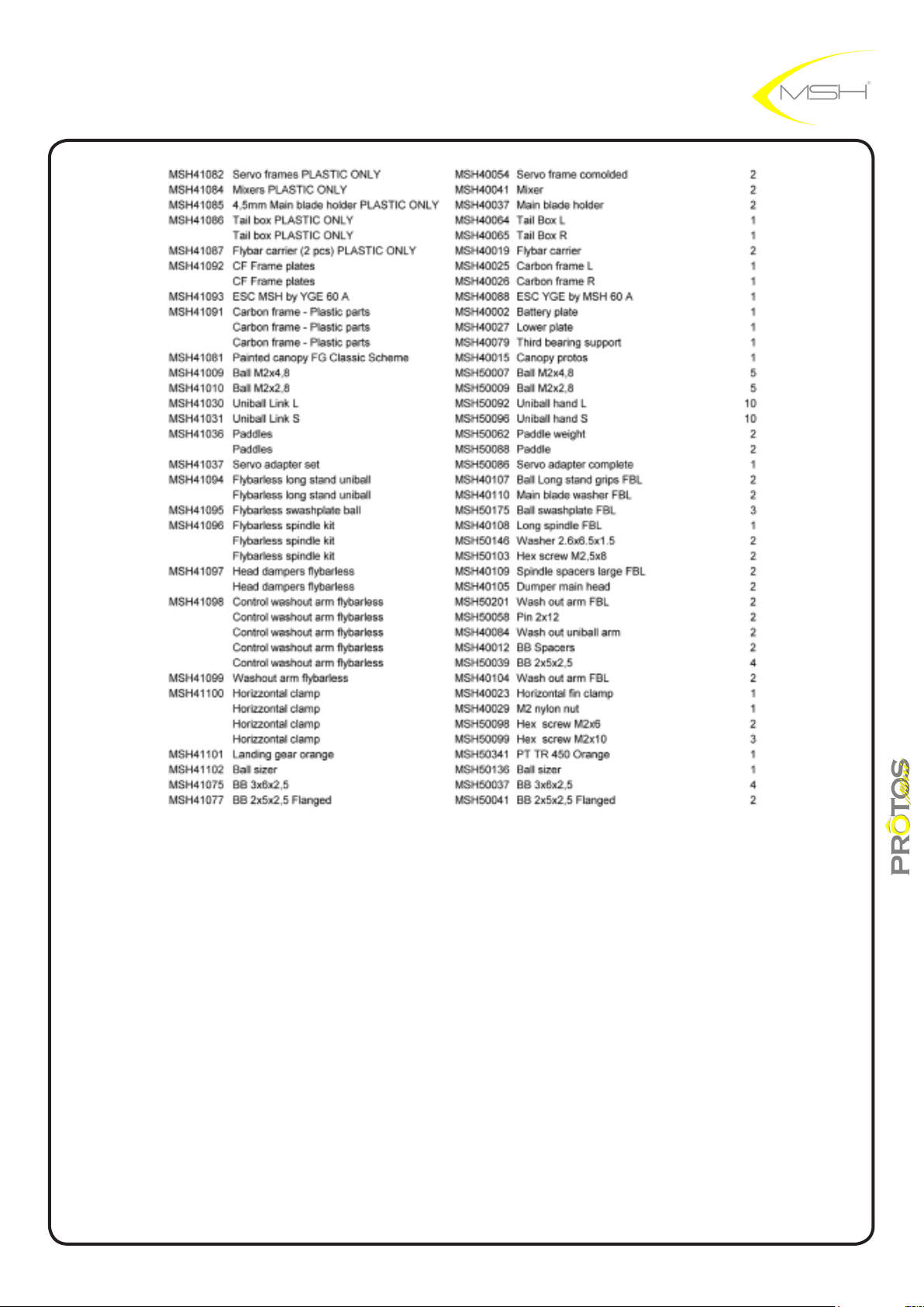
spare part list
43
instructions manual
Page 44
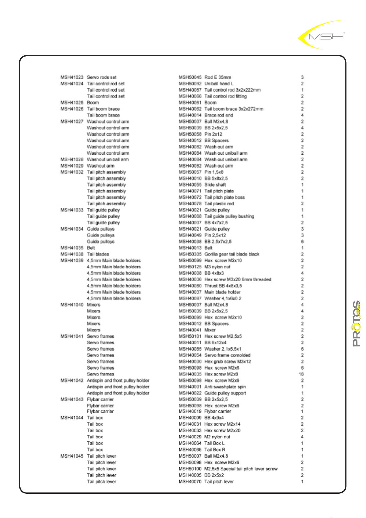
44
instructions manual
Page 45
45
instructions manual
Page 46
MSHeli s.r.l.
Saronno (VA)
ITALY
specication and design are subject to change without notice
LOCTITE are a registred mark
46
instructions manual
 Loading...