

Page 1
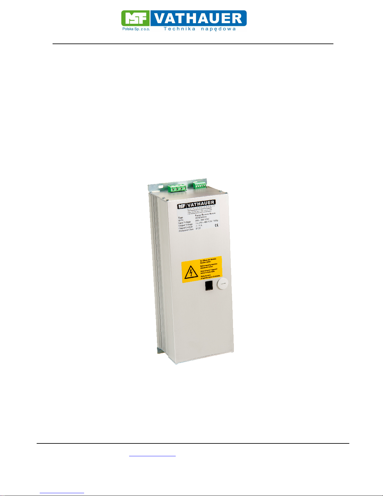
Manual ERS (Energy Recovery System)
MSF-Vathauer Polska Sp. z.o.o ul. Staszica 37 PL-64-600 Oborniki
Tel: 0048 503972873 E-mail [email protected] www.msf-technik.pl
Page 1 of 23
Manual
Energy Recovery System
Version:
23/2018 Rev. 1.5
Date: 06.06.2018
Page 2

Manual ERS (Energy Recovery System)
MSF-Vathauer Polska Sp. z.o.o ul. Staszica 37 PL-64-600 Oborniki
Tel: 0048 503972873 E-mail [email protected] www.msf-technik.pl
Page 2 of 23
Warranty
According to the current general terms of delivery and payment MSF- Vathauer
Antriebstechnik GmbH & Co. KG provides a warranty of 12 months (in single shift) after
delivery on all electronic devices covering design, material or faulty workmanship.
MSF- Vathauer Antriebstechnik reserves the right to change the contents of this operation
manual and the product specifications contained therein without prior notice.
The copyright of this documentation is reserved by
MSF-Vathauerer Antriebstechnik GmbH & Co. KG .
Attention!
Read this manual carefully and completely.
Start with the installation and commissioning only after reading.
Technical changes reserved
Page 3

Manual ERS (Energy Recovery System)
MSF-Vathauer Polska Sp. z.o.o ul. Staszica 37 PL-64-600 Oborniki
Tel: 0048 503972873 E-mail [email protected] www.msf-technik.pl
Page 3 of 23
Index
Warranty................................................................................................................................ 2
1. Safety and application notes for the ERS.......................................................................... 4
1.1. General .......................................................................................................................... 4
1.2. Intended Use.............................................................................................................. 4
1.3. Transportation and storage......................................................................................... 4
1.4. Installation.................................................................................................................. 5
1.5. Electrical connection................................................................................................... 5
1.6. Operation.................................................................................................................... 5
1.7. Maintenance and servicing......................................................................................... 5
1.8. Safety and Installation instructions.............................................................................. 6
European EMC directive.................................................................................................... 6
2. Assembly and Installation.................................................................................................. 7
2.1. Installation.................................................................................................................. 7
2.2. Cabling directives of superior controls........................................................................ 7
2.3. Measures to secure the EMC in machinery and plants............................................... 8
2.4. Grounding, earthen, potential compensation............................................................... 8
2.5. Filtering....................................................................................................................... 8
2.6. Screening signal- and control cables.......................................................................... 8
2.7. Coupling into motor cables......................................................................................... 8
3. Technical features............................................................................................................. 9
3.1. Special features.......................................................................................................... 9
3.3. Sample Application....................................................................................................10
3.4. Switching thresholds..................................................................................................11
3.5. Adjustment of the switching threshold........................................................................11
4. Connection Diagrams.......................................................................................................12
4.1. Connection diagram front side...................................................................................12
4.2. Connection diagram rear side....................................................................................12
4.3. Connection example FU with external brake chopper................................................13
4.4. Connection example FU with ERS.............................................................................13
4.5. Connection example FU interconnection with an ERS...............................................14
4.6. Connection example FU interconnecting circuit with several ERS .............................14
5. In- and Outputs.................................................................................................................15
5.1. Digital Input (DIN)......................................................................................................16
5.2. Digital Output 1 (DOUT 1)..........................................................................................16
5.3. Digital Output 2 (DOUT2)...........................................................................................16
5.4. Internal supply voltage (24Vdc)..................................................................................16
5.5. Integrated braking resistor.........................................................................................17
6. Commissioning instructions..............................................................................................18
7. Technical specifications....................................................................................................19
7.1. Electrical specifications..............................................................................................19
7.2. Measurement ERS....................................................................................................20
7.3. Front view..................................................................................................................21
7.4. Rear view ..................................................................................................................21
8. Status indications.............................................................................................................22
Notes....................................................................................................................................23
Page 4

Manual ERS (Energy Recovery System)
MSF-Vathauer Polska Sp. z.o.o ul. Staszica 37 PL-64-600 Oborniki
Tel: 0048 503972873 E-mail [email protected] www.msf-technik.pl
Page 4 of 23
1. Safety and application notes for the ERS
1.1. General
During operation the ERS can get under certain circumstances live parts and hot surfaces.
Any unauthorized removal of the required cover, inappropriate use, incorrect installation or operation
may result in death, severe injury or material damage.
All works for transportation, installation and initialization and maintenance work must be carried out by
qualified personnel (IEC 364 and CENELEC HD 384 or DIN VDE 0100 and IEC report 664 or DIN
VDE 0110 and national accident prevention regulations or VGB 4).
Qualified personnel in the context of these basic safety notes are persons familiar with installation,
assembly, commissioning and operation of the product and who possess the appropriate qualifications
(defined in IEC 364 or DIN VDE 0105).
1.2. Intended Use
The ERS is a component, which is intended for installation only in machines in commercial
installations in conjunction with a frequency inverter or a servo controller.
The commissioning of the ERS-frequency inverter or ERS-Servo controller constellation is prohibited
until it is determined that the machine in which the device is installed, complies with the provisions of
EU Directive 2006/42 / EC (Machinery Directive).
The ERS meets the protection objectives of the Low Voltage Directive 2006/95 / EC and the
harmonized standards of the EN 50178 / DIN VDE 0160 in conjunction with EN 60439-1 / DIN VDE
0660 part 500 and EN 601 146 / DIN VDE 0558.
Operation is only permitted in compliance with the EMC - law ( 2014/30/EU).
The technical data and information on the connection conditions can be obtained from the nameplate
or the documentation and must be observed.
1.3. Transportation and storage
The instructions for transportation, storage and proper handling must be observed
After delivery damages found must be reported to the transport company immediately.
Before commissioning the supplier can optionally be contacted.
Climatic conditions must be observed according to EN 50178th
Page 5

Manual ERS (Energy Recovery System)
MSF-Vathauer Polska Sp. z.o.o ul. Staszica 37 PL-64-600 Oborniki
Tel: 0048 503972873 E-mail [email protected] www.msf-technik.pl
Page 5 of 23
1.4. Installation
The installation and cooling of the device must be in accordance with the provisions of the relevant
documentation.
The ERS must be protected from excessive strain. They are to handle only in a way, so that no
components are bent and / or isolating distances altered. The contact of electronic components and
terminals must be avoided.
The ERS contain electrostatic sensitive devices. These components can be easily destroyed by
improper handling. Built-in electrical components must not be destroyed (potential health hazard).
1.5. Electrical connection
When working on live equipment and / or systems, the applicable national accident prevention
regulations (for example, VGB 4) must be observed.
The electrical installation has to be done according to the valid directives (e.g. cable diameters, fuse
protection, ground wire connection). More detailed information is to be found in the documentation.
Compliance with the limits for the plant according to the EMC juridical directive is in responsibility of
the manufacturer of the plant. Information about the EMC-compatible installation like screening,
grounding, alignment of filters and lying of cables are to be found in the documentation of the other
components.
1.6. Operation
Plants with integrated frequency inverters or servo controller with ERS must be equipped, if applicable,
with additional observation and security installations according to the concerning valid security
directives, e.g. act on technical work equipment, accident prevention regulations etc. The
documentation of the manufacturer has to be regarded.
After disconnection of the frequency inverters or the Servo controller from the supply voltage, voltage
conducting device parts and cable conductors on the ERS must not be immediately touched because
of possibly charged condensers. Please regard the according notification signs at the frequency
Inverters. During operation, all covers must keep closed.
1.7. Maintenance and servicing
The documentation of the manufacturer has to be regarded
Page 6

Manual ERS (Energy Recovery System)
MSF-Vathauer Polska Sp. z.o.o ul. Staszica 37 PL-64-600 Oborniki
Tel: 0048 503972873 E-mail [email protected] www.msf-technik.pl
Page 6 of 23
1.8. Safety and Installation instructions
The ERS is a device intended for use in industrial high-voltage plants and is operated with voltages
that can cause serious injuries or death when touching!
• Installation and other work may only be carried out by qualified specialist electricians and at a
voltage free device. The user manual must always be available to them at any time and has
to be consequently regarded.
• Local regulations for the installation of electrical systems and accident prevention regulations
must be observed.
• The device continues to carry current in the ERS, after switching off the mains at the
frequency inverter or servo controller, for up to 5 minutes dangerous voltage. Opening the
device is therefore only permitted until 5 minutes after the unit is completely free of voltage.
Before switching on the supply voltage all covers have to be reattached.
• Also at motor standstill (e.g. due to electronics lock, short circuit at the output clamps
or blocked drive) the voltage circuit clamps, motor clamps and clamps for the brake
resistance may conduct dangerous voltage. A motor standstill is not identical with
a galvanic disconnection from the mains voltage.
• Attention: The ERS may after the mains are switched on, depending on the settings,
start automatically the regenerative mode.
Attention! Danger to Life!
The power supply conducts voltage under certain circumstances for up to 5 minutes
after turning off the mains voltage. Terminals, DC lines and network terminals may be
alive!
Touching open or free terminals, cables and device parts may cause serious injuries
or death!
Attention
• Children and the public must not have access to the device!
• The device may only be used for the purpose intended by the manufacturer. Unauthorized
changes and the use of replacement parts and additional devices that are not sold or
approved by the manufacturer may cause fire, electric shocks and injuries.
• Keep the manual in reach and make it available for every user!
European EMC directive
IF a frequency inverter is installed in conjunction with an ERS as recommended by this manual, it will
meet the requirements of the EMC Directive, in accordance with the EMC product standard for motoroperated systems EN 61800-3, provided it was previously fulfilled by the frequency inverter.
Page 7

Manual ERS (Energy Recovery System)
MSF-Vathauer Polska Sp. z.o.o ul. Staszica 37 PL-64-600 Oborniki
Tel: 0048 503972873 E-mail [email protected] www.msf-technik.pl
Page 7 of 23
2. Assembly and Installation
2.1. Installation
The device requires adequate ventilation.
The hot air has to be dissipated above the ERS!
2.2. Cabling directives of superior controls
The ERS is developed for the operation in industrial environments where high values of
electromagnetic interferences are expected. In general, a professional installation ensures a risk less
and error-free operation. If limits are required that exceed the EMC directive limits, the following
directives are recommended.
1. Please make sure that all devices in the control cabinet are connected together at a shared
grounding point or rail with short cores and great diameter are properly grounded. It is
especially important that every control device connected to the frequency inverter and the
ERS (e.g. automation devices) is connected via a short core with high diameter at the same
grounding point as well as the frequency inverter and the ERS itself.
2. The PE conductor of the motor controlled by the frequency inverter should preferably directly
connected to the ground connection, connected with the heat sink together with the PE of the
power supply of the concerning inverter. The existence of a central grounding rail within the
control cabinet and the connection of alll PE conductors to this rail normally guarantee an
error-free operation.
3. As far as possible screened cables for the control should be used. The cable ends have to be
terminated carefully and ensure that the cores are not unscreened over long distances. The
screen of analogue set point cables should only be grounded at the frequency Inverter singlesided. Not used cores of the control cable should be grounded.
4. The control cables have to be laid in the most possible distance from the load cable using
separated cable trenches etc. Cable crosses should possibly get an angle of 90°.
5. Make sure that contactors and relays in the control cabinets are suppressed either by RC
connection or varistors in case of AC contactors or by „ freewheeling diodes “at DC
contactors, wherein the interference suppression bust be attached to the coils. The
suppression is especially important if the contactors are controlled by the relay in the
frequency Inverter (optional).
6. Use screened cores for the load connections and ground the screening at both ends, if
possible directly at the PE output of the Inverter.
7. If the drive should run within an environment sensible to electro-magnetic interference, the
usage of interference filters is recommended to reduce the grid-bound and radiated
interferences of the Inverter. In this case install the filter as near as possible to the inverter and
take care and be well grounded.
8. Choose the lowest possible switching frequency. This minimizes the intensity of the electromagnetic interference created by the frequency Inverter.
During the installation of the ERS at the frequency inverter the safety regulations must not be
violated!!! Instructions of the Inverter manufacturer have to be observed!!!!
Page 8

Manual ERS (Energy Recovery System)
MSF-Vathauer Polska Sp. z.o.o ul. Staszica 37 PL-64-600 Oborniki
Tel: 0048 503972873 E-mail [email protected] www.msf-technik.pl
Page 8 of 23
2.3. Measures to secure the EMC in machinery and plants
The following measures are to secure the EMC, which are of absolute necessity to the Inverter
technology. The Inverter fulfills the demands of the high noise immunity and the slight-noise emissions
for the usage in industries, under the guidelines of this manuals installation consideration
.
2.4. Grounding, earthen, potential compensation
The correct professional grounding or earthen guarantees the protection of the staff against
dangerous touch voltages (input, output and intermediate circuit voltage) and through parasitic current
inductance and low-impedance potential compensation an important measure to reduce
electromagnetic influences.
2.5. Filtering
Filters are inserted into the lead-bound transfer way between the source of interference and the
interference suppressor, which is to reduce lead-bound transmissions and to increase the noise
immunity. Additional, external filter may have a negative effect on the noise emission!
2.6. Screening signal- and control cables
Screening is used for decoupling fields between two spatially separate areas, i.e. is also used to
decrease the emission of electromagnetic radiation and to increase the noise immunity. The consistent
use of metal cases is one of the most important standard measures to safeguard the EMC.
2.7. Coupling into motor cables
The use of twisted core cables can essentially reduce inductive couplings into a circuit. Cable screens
must reduce capacitive, inductive and electromagnetic interferences. It is important to note that to
reduce low frequency capacitive interference, it is often sufficient to place a one sided screening,
whereas inductive and high frequency electromagnetic interference can only be prevented by
screening both sides of the cable.
The screening must not be used as a protection earthen!!!
Page 9

Manual ERS (Energy Recovery System)
MSF-Vathauer Polska Sp. z.o.o ul. Staszica 37 PL-64-600 Oborniki
Tel: 0048 503972873 E-mail [email protected] www.msf-technik.pl
Page 9 of 23
3. Technical features
The ERS is a regenerative power supply unit with optimized price-performance ratio and high degree
of protection, thus, the use is already worthwhile even with small energy surplus quantities. Assembly
is made with mounting aids directly on the device.
The centerpiece is a DSP signal processor for generating the pulse pattern and addressing all
applicable control tasks and to safeguard the integrated protection functions.
Through advanced semiconductors and sophisticated control technology and control engineering,
enables the device to recover energy with an efficiency> 95%
3.1. Special features
The ERS is directly connected to the intermediate circuit of the inverter or the servo controller. The
voltage is monitored and upon reaching the respective threshold the feedback mode is automatically
activated.
The thresholds are adjustable via a selector switch inside the unit
The ERS operates on 3ph AC voltage network and synchronizes automatically at the connection.
There is no programming required. The device is immediately ready after turning on the inverter or the
servo controller and the synchronization with the utility grid.
High operational safety due to:
• High interference immunity and low noise emission by built-in filters
• Electrically isolated enable input
• Electrically isolated digital output (for example: synchronization successfully)
• Device temperature monitoring of critical components
• Current monitoring and shutdown
• Continuous monitoring and measurement of all 3 mains phases
• Continuous monitoring and measurement of the intermediate circuit voltage
• Preset device parameters
• Easy handling
• Fast commissioning
3.2. Functional Description
Page 10

Manual ERS (Energy Recovery System)
MSF-Vathauer Polska Sp. z.o.o ul. Staszica 37 PL-64-600 Oborniki
Tel: 0048 503972873 E-mail [email protected] www.msf-technik.pl
Page 10 of 23
The control electronics of the ERS is supplied with energy via the DC bus voltage of the inverter or the
servo controller. The integrated power supply generates all internal and external (DIN / OUT)
essentials voltages. The intermediate circuit voltage is continuously measured and monitored
analogously. Subsequently, the synchronization to the supply grid is done whose state is signaled by a
visual indicator (LED). All three external line voltages are continuous analogously measured and fed to
the control algorithm. Once the DC link voltage has reached the threshold (Sec.3.4) begins the ERS
with the feedback of energy into the grid.
Important requirements for the operation of the ERS:
- For the operation of the ERS is an 3phase Power grid necessary.
-
The frequency inverter or the servo controller must establish a relationship to the power
supply via an uncontrolled rectifier (B6U).
-Regenerative feedback operation is only possible if the intermediate circuit voltage is higher
than the amplitude value of the line voltage (at sinusoidal supply voltage Vrms * √2).
-The connection of the ERS to the terminals of the brake chopper resistance is NOT permitted
3.3. Sample Application
Nominal voltage 400 Vac, U-Chopper 680Vdc
Operating on a system consisting of FU with brake chopper, ERS (sec.5.4)
Page 11

Manual ERS (Energy Recovery System)
MSF-Vathauer Polska Sp. z.o.o ul. Staszica 37 PL-64-600 Oborniki
Tel: 0048 503972873 E-mail [email protected] www.msf-technik.pl
Page 11 of 23
3.4. Switching thresholds
Application and device-specific, the brake chopper is activated at different voltage thresholds of the
intermediate circuit voltages. This requires that the turn-on / off thresholds of the ERS can be adapted
to the application requirements.
To be able to lead as much energy back into the supply network, it is advisable to select the turn-on
thresholds so that the regenerative operation begins before the brake chopper - engagement.
The switch-on threshold for the energy feedback must be set to the frequency inverter or servo
controller specific at the ERS. Please refer to the respective manufacturer for the thresholds of the
respective frequency inverter or servo drive.
Switch Turn-On- / Off threshold
(Feedback activated/deactivated
0 540 V
1 560 V
2 580 V
3 600 V
4* 620 V
5 640 V
6 660 V
7 680 V
8 700 V
9 720 V
A 740 V
B 760 V
C 780 V
D reserved
E reserved
F reserved
* MSF factory setting
3.5. Adjustment of the switching threshold
A selector switch is provided in the device interior for setting the switching threshold.
In order to be able to make changes to this switch, a cover in the housing cover adjacent to the
window must be screwed open with a suitable tool.
The setting on the coding switch is only to be carried out with a VDE-insulated tool. Please make
sure, when inserting and removing the tool, no further electronic components are touched or even
damaged in the housing interior.
After the setting has been carried out, the cover in the housing cover next to the window must be
screwed back on with a suitable tool.
Page 12
Manual ERS (Energy Recovery System)
MSF-Vathauer Polska Sp. z.o.o ul. Staszica 37 PL-64-600 Oborniki
Tel: 0048 503972873 E-mail [email protected] www.msf-technik.pl
Page 12 of 23
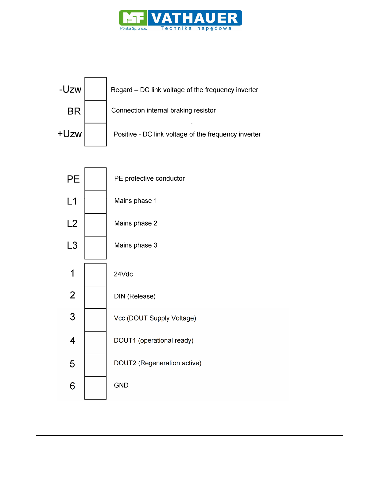
4. Connection Diagrams
4.1. Connection diagram front side
4.2. Connection diagram rear side
Page 13

Manual ERS (Energy Recovery System)
MSF-Vathauer Polska Sp. z.o.o ul. Staszica 37 PL-64-600 Oborniki
Tel: 0048 503972873 E-mail [email protected] www.msf-technik.pl
Page 13 of 23
4.3. Connection example FU with external brake chopper
4.4. Connection example FU with ERS
Page 14

Manual ERS (Energy Recovery System)
MSF-Vathauer Polska Sp. z.o.o ul. Staszica 37 PL-64-600 Oborniki
Tel: 0048 503972873 E-mail [email protected] www.msf-technik.pl
Page 14 of 23
4.5. Connection example FU interconnection with an ERS
* FU must be suitable for intermediate circuit connection
4.6. Connection example FU interconnecting circuit with several ERS
Page 15

Manual ERS (Energy Recovery System)
MSF-Vathauer Polska Sp. z.o.o ul. Staszica 37 PL-64-600 Oborniki
Tel: 0048 503972873 E-mail [email protected] www.msf-technik.pl
Page 15 of 23
* FU must be suitable for intermediate circuit connection
5. In- and Outputs
Page 16

Manual ERS (Energy Recovery System)
MSF-Vathauer Polska Sp. z.o.o ul. Staszica 37 PL-64-600 Oborniki
Tel: 0048 503972873 E-mail [email protected] www.msf-technik.pl
Page 16 of 23
5.1. Digital Input (DIN)
The ERS has a digital input (Section 4.2.). This input releases the power electronics of the control unit
and must be connected for the feedback mode.
The reference potential for the digital input is terminal 6 (DGND). To activate the input, an external
power supply or the provided voltage on terminal 1 (24Vdc) can be used.
The digital input is designed for a control voltage range of 12 - 30V @ 5mA.
5.2. Digital Output 1 (DOUT 1)
The ERS has a digital output 1 (sect.4.2.). This output indicates the status of the network
synchronization. If the mains synchronization was successful and if there is no fault such as
overtemperature or overcurrent, then this is signaled with a voltage level from terminal 3 (Vcc) to
terminal 4.
The reference potential for the digital output is the terminal 6 (DGND). As supply voltage, an external
power source or the on to terminal 1 (24Vdc) provided voltage can be used.
The Open - Emitter - output is for maximum 30V / 40mA load
As external power source may be max. 30V used
5.3. Digital Output 2 (DOUT2)
The ERS has a digital output 2 (sect 4.2). This output shows the status of the feedback. Upon
reaching the switch clamp (sec.3.4.), the current flows in the system network. This is signaled
internally by a green LED and with a voltage level from terminal 3 (Vcc) to terminal 5.
The reference potential for the digital output is terminal 6 (DGND). The supply voltage can be
an external voltage source or the voltage supplied to terminal 1 (24Vdc).
The Open - Emitter - output is for maximum 30V / 40mA load
As external power source may be max. 30V used
5.4. Internal supply voltage (24Vdc)
The ERS provides a SELV isolated supply voltage amounting to 24Vdc. This voltage source is
protected by a resettable fuse.
The reference potential for the digital output is the terminal 6 (DGND).
The 24Vdc is loaded with a maximum of 100mA
Page 17

Manual ERS (Energy Recovery System)
MSF-Vathauer Polska Sp. z.o.o ul. Staszica 37 PL-64-600 Oborniki
Tel: 0048 503972873 E-mail [email protected] www.msf-technik.pl
Page 17 of 23
The 24Vdc is executed with a tolerance of +/- 10%.
5.5. Integrated braking resistor
Error-free operation of the ERS requires a three-phase supply network. If this network fails or one of
the three phases is missing, then the devise goes into malfunction and can not return any regenerative
energy. In this case, there is the possibility to use the built in emergency resistor. However, this
assumes that of the frequency inverter or servo controller in use has a built-in brake chopper
connection and that the integrated resistor meets the application requirements.
The emergency resistor is permanently loaded with 100W.
Page 18

Manual ERS (Energy Recovery System)
MSF-Vathauer Polska Sp. z.o.o ul. Staszica 37 PL-64-600 Oborniki
Tel: 0048 503972873 E-mail [email protected] www.msf-technik.pl
Page 18 of 23
6. Commissioning instructions
For quick setup and trouble-free operation of the ERS the following procedure is recommended when
commissioning.
1. If it is in an existing plant and a brake chopper is used, it is recommended that the voltage across
the resistor is looked at with a suitable instrument (Multimeter, oscilloscope, etc.).
Based on the maximum operating voltage you can make the default setting of thresholds (sec. 3.4.) at
the ERS. Alternatively, the switching thresholds of the brake chopper can be taken from the technical
documentation or requested of the device manufacturer of the frequency inverter or servo drive.
2. Switch the controller without voltage
3. Connect the ERS to the DC link terminals of the inverter or the servo controller (e.g. sec. 4.3. / 4.4.).
To comply with EMC, it is advisable to use a shielded cable and the shielding on both sides.
!!! IMPORTANT: Please note the polarity of the DC link voltage. It is NOT a polarity protection in
the ERS integrated
4. Connect the ERS with the 3-phase supply network
!!! IMPORTANT: The operation of the ERS is only possible on a CLOCKWISE ROTATING
FIELD!!!!!!
5. If necessary, connect the inputs / outputs of the ERS with your application.
!!! RECOMMENDATION: During the initial commissioning it is recommended that the enable
input (sec. 5.1.) when switching on the controller is not set to!!!!!!
6. Switch on the controller
7. After a moment, a visual indicator appears in the ERS (sec. 8.)
8. If network synchronization was successful and no other error is displayed, "Enable" can be set.
This is indicated by visual display (sec.8.)
9. Subsequently, a test run can be performed
!!! INFO: The feedback operation of the ERS is visually displayed (sec. 8.)!!!
!!!TIP: Set the switching thresholds so that the brake chopper is used as little as possible or
not at all in normal mode!!!
!!! IMPORTANT: Please note that the feedback mode is possible only with existing 3-phase
voltage. If during the regenerative operation or shortly before it comes to a fault, it is
recommended to provide a braking resistor for emergency braking!!!
Page 19

Manual ERS (Energy Recovery System)
MSF-Vathauer Polska Sp. z.o.o ul. Staszica 37 PL-64-600 Oborniki
Tel: 0048 503972873 E-mail [email protected] www.msf-technik.pl
Page 19 of 23
7. Technical specifications
7.1. Electrical specifications
Type ERS
Input voltage 500 – 900Vdc
Input
The inverter side
Integrated resistor
100Ohm/100W
Energy recovery power
voltage ***
3x350-480V
Mains filter Internal
Output
Mains side
Mains frequency 50/60 Hz
Regenerative power
2-9A (ca.5kW) @ ED35%
ca.2kW @ ED100%
Protection class
IP 20
(optional IP 54)
General Data
Ambient temperature 0 – 40 °C
Humidity
20 – 90 % rel.
Not dewing
Dimensions
IP20 312 x 112 x 92 mm
IP54 434 x 112 x 92 mm
Weight 2,1kg
*** The feedback operation is only possible (Sec. 3.2) if the DC link voltage is above the amplitude
value of the line voltage is (at sine shaped mains voltage Vrms * √2).
Experience value for regenerative threshold: (Un + 10%) * √2 + 6%
Example: Un = 400Vac feedback threshold = 660Vdc
Page 20

Manual ERS (Energy Recovery System)
MSF-Vathauer Polska Sp. z.o.o ul. Staszica 37 PL-64-600 Oborniki
Tel: 0048 503972873 E-mail [email protected] www.msf-technik.pl
Page 20 of 23
7.2. Measurement ERS
Dimension ERS IP20 ERS IP54
A 65 mm 65 mm
B 290 mm 370 mm
C 312 mm 392 mm / 434 mm**
D 90 mm / 92mm* 90 mm / 92mm*
E 112 mm 112 mm
F 5 mm 5 mm
* Height
incl. cover for the selector switch
** Length including cable glands at the top and bottom
Page 21

Manual ERS (Energy Recovery System)
MSF-Vathauer Polska Sp. z.o.o ul. Staszica 37 PL-64-600 Oborniki
Tel: 0048 503972873 E-mail [email protected] www.msf-technik.pl
Page 21 of 23
7.3. Front view
7.4. Rear view
AC-mains
Window and selector
switch
IO - Terminals
DC link connection
Page 22

Manual ERS (Energy Recovery System)
MSF-Vathauer Polska Sp. z.o.o ul. Staszica 37 PL-64-600 Oborniki
Tel: 0048 503972873 E-mail [email protected] www.msf-technik.pl
Page 22 of 23
8. Status indications
All Status indications can be viewed via the display window. Status of network synchronization is also
displayed by the digital output (sec. 5.2./5.3).
Error code Meaning
LED RED
Lights = fault overcurrent
Flashing (slow 1Hz) = temperature warning
Flashing (fast 0.5Hz) = temperature cut-off
LED GREEN Feedback mode active
LED YELLOW
Lights = release set
Flashing = no release set
LED BLUE
Lights = Network synchronization successful
Flashing = No network synchronization
Note: The error can be confirmed by setting / resetting of the release.
Page 23

Manual ERS (Energy Recovery System)
MSF-Vathauer Polska Sp. z.o.o ul. Staszica 37 PL-64-600 Oborniki
Tel: 0048 503972873 E-mail [email protected] www.msf-technik.pl
Page 23 of 23
Notes
 Loading...