


Product Guide
WMPD3
WMPAD3
WMPAD3-L
today, tomorrow and in the future
mselectronics.co.uk
Wall Mounted
Presence/Absence Detectors
3-wire versions
WMPD3 Presence Detector
WMPAD3 Presence/Absence Detector
WMPAD3-L with LED indicator
energy saving controls
Issue 1.0
WMPD3 · WMPAD3 · WMPAD3-L
2
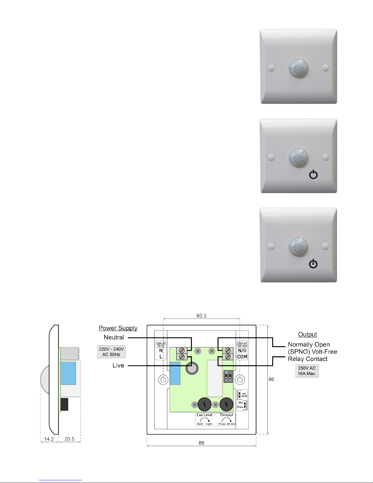
Figure 2 Typical wiring example and dimensions (in millimetres)
Product Overview
The Wall Mounted Presence/Absence Detector range provides
exible occupancy-based switching for lighting, heating, air
conditioning and ventilation equipment. The built-in PIR (passive
infra-red) sensor detects motion of body heat, providing
convenient activation of the connected load whilst saving energy
by switching it off automatically when the space becomes
unoccupied (after an adjustable period). An adjustable ambient
light threshold optionally inhibits initial activation when the area is
adequately lit, reducing wasteful use of lighting..
• The WMPD3 Presence Detector offers fully-automatic
operation, switching on the load upon detection of motion, and
switching off when the area has been unoccupied for the set
period.
• The WMPAD3 Presence/Absence Detector includes a
touch-sensitive override button and offers the exibility of
two operating modes to suit either manual or automatic initial
activation.
• The WMPAD3-L provides an illuminated button to aid location
of the unit in the dark (when used in Absence Mode). The LED
also acts to facilitate accurate setup of the light sensor function.
The units are simple to install and t a standard single-gang UK
pattress or back box (22mm min. depth). Ideal applications include
small booths or rooms, workshops, entrance halls, staircases,
toilets, store cupboards, hired sports courts and rooms plus many
more.
Figure 1a WMPD3
Figure 1b WMPAD3
Figure 1c WMPAD3-L
3
mselectronics.co.uk
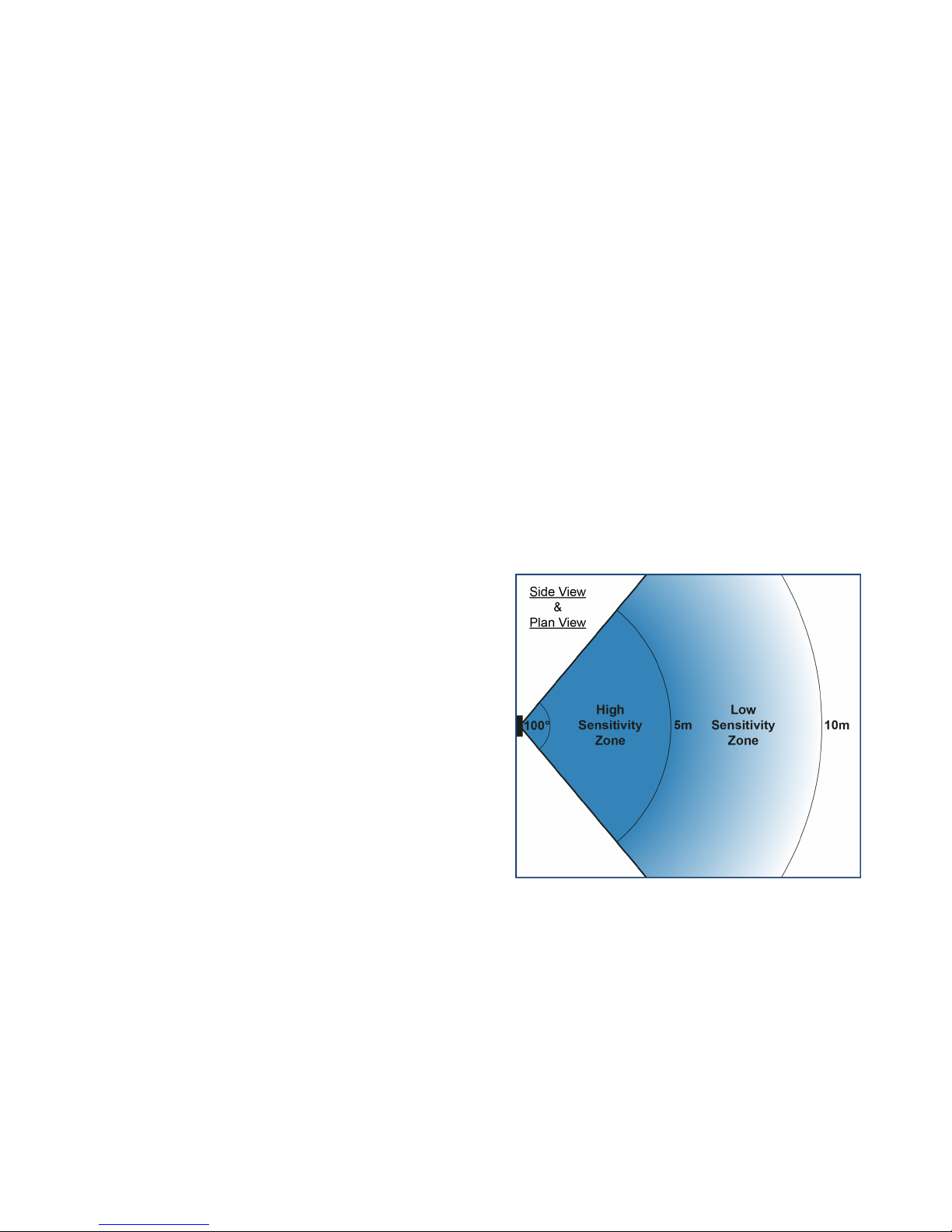
Positioning
Figure 3 illustrates the typical detection pattern
of the PIR sensor when the unit is wall-mounted.
Ensure that the proposed mounting position will
offer the required area of detection.
High Sensitivity Zone:
Detects e.g. arm movement.
Low Sensitivity Zone:
Detects e.g. whole body movement.
Tips
• The sensor is most sensitive to motion across
its eld of view, rather than directly towards or
away from the sensor.
• Avoid mounting the unit close to a light or heat
source (the one being switched, or otherwise)
since this may interfere with the detection.
• Multiple units may be wired in parallel to
extend the detection eld – see Using Multiple
Detectors.
Figure 3 PIR sensor detection pattern
Electrical Requirements
Before attempting to install the unit, ensure that the intended load and wiring arrangement
comply with the following requirements. Figure 2 shows a typical wiring example.
• 3-wire (live/neutral + volt-free switch) connection: The unit requires a permanent
live/neutral connection, and as such is not suitable for replacing an existing light switch
with no neutral conductor at the switch location. A volt-free relay output is provided,
which can be used to switch a load on the same mains supply (by connecting across
from L to COM, making N/O a switched ‘Live Out’), or to provide a contact closure to a
separate load or control signal. There is no minimum load requirement.
Also available: WMPD2 / WMPAD2 / WMPAD2-L (2-wire versions) – Suitable for ‘inline’
connection with the load to be switched (no neutral required), such as to replace a
standard light switch. A minimum load of 20W (per detector) applies; a load capacitor is
required for smaller loads.
• Maximum load: The maximum load rating is 16A (4000W), however for high inrush
loads (such as most types of lighting) a lower limit applies: see Technical Specication.

WMPD3 · WMPAD3 · WMPAD3-L
4
Installation
All electrical installation and maintenance must be carried out by a competent person. If in doubt,
consult a qualied electrician. Any new wiring must be carried out by qualied personnel in
accordance with the current edition of the IET Wiring Regulations (BS7671).
!
Ensure the electrical supply is isolated before making any connections or adjustments.
!
1. Select a suitable location for the unit (following the guidelines under Positioning) and
prepare a single-gang pattress or back box as necessary.
2. Adjust the controls according to the operational requirements.
WMPD3 only There there are no switches present on this model.
− Rotate the Timeout and Lux Level thumbwheels to the desired settings. For nonlighting loads, ensure the latter is set correctly. See Controls below.
WMPAD3-L only The button illumination LED may be used to assist setup of the Lux
Level control: see LED Indicator below.
− WMPAD3(-L) Using e.g. a small screwdriver, move Switch 2 to select the desired
operating mode according to the accompanying label: see Controls below.
3. Connect the wiring as shown in Figure 2 (or in any suitably appropriate form).
− Supply connections (L, N): Use appropriate mains cable to power the unit. If the
load is also powered via this wiring, ensure the current rating is adequate. Otherwise
(i.e. if the output is independently powered), low-current cable may be used.
− Load connections (COM, N/O): Use cable rated for the load current and voltage.
4. Fix the unit into position with the two screws and caps supplied.
Controls
• Timeout (10 seconds to 60 minutes): Sets the period of time over which no motion must
be detected, after which the load is switched off.
• Lux Level: Sets the ambient light level threshold, below which the unit will permit
activation upon detecting motion. For non-lighting loads, and in other cases where
operation should be permitted at any light level, turn the control fully towards ‘Light’.
• Operating Mode WMPAD3(-L): Select either Presence Mode (‘Pres.’) or Absence Mode
(‘Abs.’). See Operation for details.
Additional Guidelines
• WMPAD3(-L) Switch 1 is not used on these models and should not be adjusted.
• The screw caps may be removed at a later date with the aid of an adhesive putty such
as Blu-Tack.
LED Indicator WMPAD3-L only
The LED indicator lights when the load is off, and the ambient light is below the threshold
set by the Lux Level thumbwheel. As well as aiding location of the unit in darkness (when
used in Absence Mode), it can be used to check that the Lux Level setting is appropriate.
The electrical supply to the unit MUST be isolated before making adjustments.

5
mselectronics.co.uk
Operation
The diagrams below illustrate the sequence of operation, according to the model and
operating mode of the unit.
Operation Notes
• After establishing the mains supply to the unit, the PIR sensor requires approx. 1 minute
to stabilise before motion detection is possible.
• If the unit does not respond to motion during testing, remember that the ambient light
level must be low enough (with respect to the Lux Level setting) to permit activation.
• The Lux Level setting only affects whether motion will switch the load on. Once on, any
motion detected will prevent the timeout from expiring, regardless of the light level.
WMPAD3(-L) In Absence Mode, the light sensor is not used since the load is switched on
manually.
Key
WMPAD3(-L)
Absence Mode
WMPAD3(-L)
Presence Mode
WMPD3 only

WMPD3 · WMPAD3 · WMPAD3-L
6
Using Multiple Detectors
If the detection pattern of the unit does not fully cover the desired area, multiple units may
be connected in parallel to extend the detection coverage.
The following wiring example is intended only as a recommendation. Proper wiring practice must be
observed with relevance to the particular installation.
!
Figure 4 illustrates a typical wiring arrangement using two WMP(A)D3 units; Figure 5
represents the same conguration as applied to a typical ceiling rose lighting circuit. This
method can typically reuse pre-existing wiring from a 2-way switching installation, where
3-core cable has been used between the switch locations.
Each unit detects motion independently and operates its own timing cycle, but the load
is shared. When either or both units detect motion (or are overridden to ‘ON’ using their
respective touch-sensitive button), the load will switch on. Once both units have detected
no motion for their respective timeouts, the load will switch off.
WMPAD3(-L) When using the override button to switch the load off, the load will remain
powered if the other unit is still in the ‘ON’ state.
Figure 4 Typical wiring schematic for two units
Figure 5 Typical ceiling rose plan

7
mselectronics.co.uk
TechnicalSpecication
Power supply 220V - 240V AC 50Hz (live/neutral)
Output switch type Volt-free SPST (normally open) relay
Output switch rating 16A, 250V AC (resistive)
Maximum lighting load
Incandescent: 12A (3000W)
Fluorescent: 10A (2500W)
Compact Fluorescent: 10A (2500W)
Timeout selection 10 seconds to 60 minutes
Detection angle 100°
Detection range
High sensitivity: up to 5m
Low sensitivity: up to 10m
Mounting hardware 22mm (min.) single-gang UK pattress box
Operating temperature -10°C to +40°C
Guarantee 5 Years
Weight 87g
Dimensions 86mm x 86mm x 35mm
Fault Finding
Ensure the electrical supply to the unit is isolated before making any adjustments.
!
Load will not switch on
a) Unit is not powered
• Ensure the unit is correctly connected to an active mains supply.
b) Load is not connected correctly
• Ensure the load is connected appropriately. The relay output is volt-free so must be
connected suitably to a supply in order to power a load.
• Check that the load works on its own by bypassing the detector.
c) Unit is not set up correctly
• WMPAD3(-L) Ensure the operating mode has been selected appropriately. In
Absence Mode, the override button must be used to switch on the load.
• Wait 1 minute after connecting the mains supply for the PIR sensor to stabilise.
• Ensure the Lux Level setting is appropriate (including for non-lighting loads).
• Ensure the unit is sited away from strong light and heat sources.
Load does not switch off, or switches on unexpectedly
• Ensure the set period is allowed to elapse with no motion in the detection zone.
• Ensure the unit is sited away from strong light and heat sources, including the load.
• Ensure there are no other inadvertent sources of triggering. To test this, tape thick
paper or card over the sensor lens (and wait for the set timeout period to elapse).

e: info@mselectronics.co.uk
t: 0333 666 1176 f: 0333 666 1436
mselectronics.co.uk
Follow us on twitter: @mselec
MS Electronics reserves the right to change this specification without prior notice.
energy saving controls
Technical Support
For further help or information on this and other products in the MS Electronics range
visit www.mselectronics.co.uk or call 0333 666 1176.
Alternatively, email techsupport@mselectronics.co.uk
Additional copies of this product guide can be downloaded from our website.
Product Warranty
MS Electronics guarantees all their products against manufacturing defects for
5 years from the purchase date. If your product is found to be faulty, MS Electronics will,
at their discretion, repair or replace the product free of charge.
Note
Any modification or damage to the product including damage due to abuse or
incorrect wiring may invalidate the guarantee.
 Loading...