

MS Electronics WMPD3, WMPAD3, WMPAD3-L Product Manual

Product Guide
WMPD3
WMPAD3
WMPAD3-L
today, tomorrow and in the future
mselectronics.co.uk
Wall Mounted
Presence/Absence Detectors
3-wire versions
WMPD3 Presence Detector
WMPAD3 Presence/Absence Detector
WMPAD3-L with LED indicator
energy saving controls
Issue 1.0
WMPD3 · WMPAD3 · WMPAD3-L
2
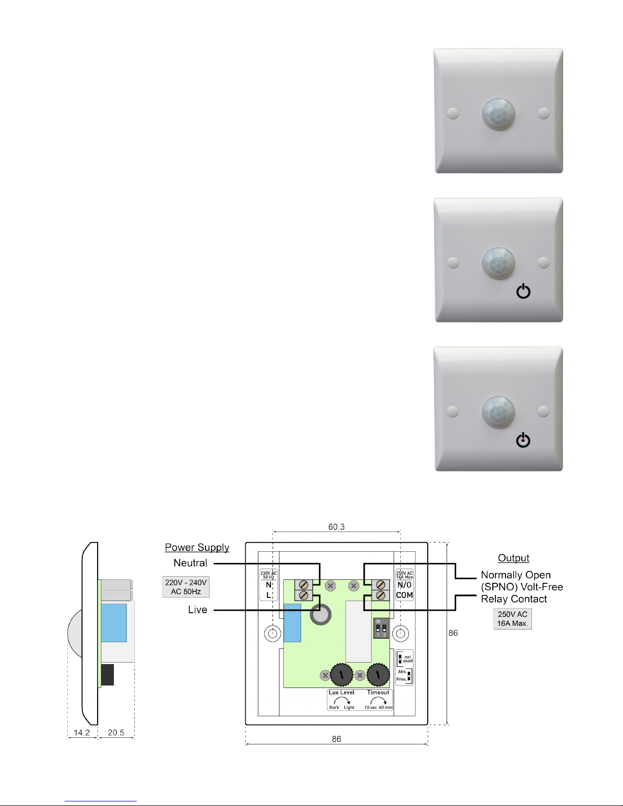
Figure 2 Typical wiring example and dimensions (in millimetres)
Product Overview
The Wall Mounted Presence/Absence Detector range provides
exible occupancy-based switching for lighting, heating, air
conditioning and ventilation equipment. The built-in PIR (passive
infra-red) sensor detects motion of body heat, providing
convenient activation of the connected load whilst saving energy
by switching it off automatically when the space becomes
unoccupied (after an adjustable period). An adjustable ambient
light threshold optionally inhibits initial activation when the area is
adequately lit, reducing wasteful use of lighting..
• The WMPD3 Presence Detector offers fully-automatic
operation, switching on the load upon detection of motion, and
switching off when the area has been unoccupied for the set
period.
• The WMPAD3 Presence/Absence Detector includes a
touch-sensitive override button and offers the exibility of
two operating modes to suit either manual or automatic initial
activation.
• The WMPAD3-L provides an illuminated button to aid location
of the unit in the dark (when used in Absence Mode). The LED
also acts to facilitate accurate setup of the light sensor function.
The units are simple to install and t a standard single-gang UK
pattress or back box (22mm min. depth). Ideal applications include
small booths or rooms, workshops, entrance halls, staircases,
toilets, store cupboards, hired sports courts and rooms plus many
more.
Figure 1a WMPD3
Figure 1b WMPAD3
Figure 1c WMPAD3-L
3
mselectronics.co.uk
Positioning
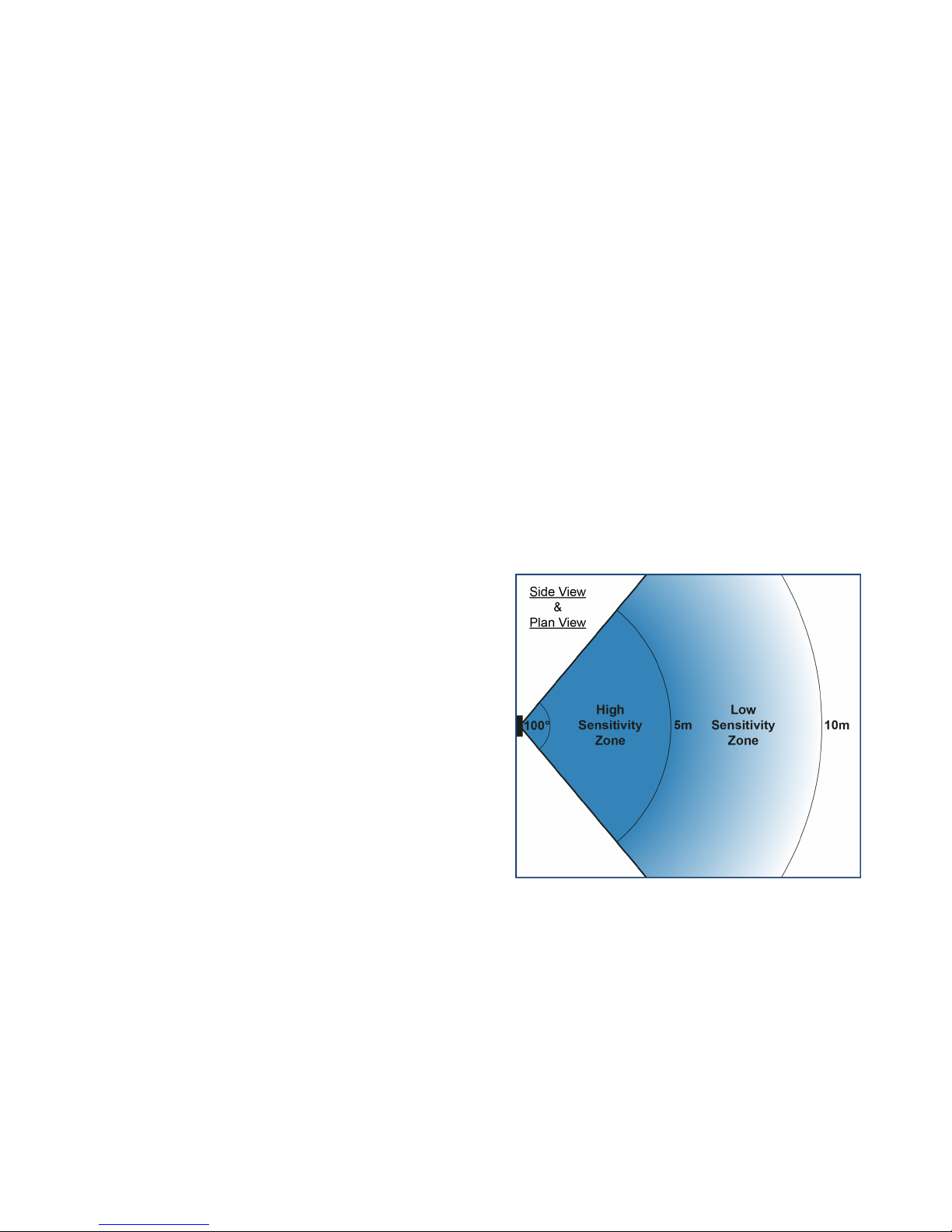
Figure 3 illustrates the typical detection pattern
of the PIR sensor when the unit is wall-mounted.
Ensure that the proposed mounting position will
offer the required area of detection.
High Sensitivity Zone:
Detects e.g. arm movement.
Low Sensitivity Zone:
Detects e.g. whole body movement.
Tips
• The sensor is most sensitive to motion across
its eld of view, rather than directly towards or
away from the sensor.
• Avoid mounting the unit close to a light or heat
source (the one being switched, or otherwise)
since this may interfere with the detection.
• Multiple units may be wired in parallel to
extend the detection eld – see Using Multiple
Detectors.
Figure 3 PIR sensor detection pattern
Electrical Requirements
Before attempting to install the unit, ensure that the intended load and wiring arrangement
comply with the following requirements. Figure 2 shows a typical wiring example.
• 3-wire (live/neutral + volt-free switch) connection: The unit requires a permanent
live/neutral connection, and as such is not suitable for replacing an existing light switch
with no neutral conductor at the switch location. A volt-free relay output is provided,
which can be used to switch a load on the same mains supply (by connecting across
from L to COM, making N/O a switched ‘Live Out’), or to provide a contact closure to a
separate load or control signal. There is no minimum load requirement.
Also available: WMPD2 / WMPAD2 / WMPAD2-L (2-wire versions) – Suitable for ‘inline’
connection with the load to be switched (no neutral required), such as to replace a
standard light switch. A minimum load of 20W (per detector) applies; a load capacitor is
required for smaller loads.
• Maximum load: The maximum load rating is 16A (4000W), however for high inrush
loads (such as most types of lighting) a lower limit applies: see Technical Specication.
 Loading...