

MS Electronics RTDS3, RTDS2 Product Manual

Product Guide
RTDS3
today, tomorrow and in the future
mselectronics.co.uk
Remote Time Delay Switch
3-wire version
energy saving controls
Issue 1.0
RTDS3
2
Product Overview
The RTDS3 Remote Time Delay Switch provides timed switching for lighting, heating, air
conditioning and ventilation equipment, to be used with a separate switch or interfaced
to a control system such as a building management system (BMS). Housed behind a
vandal-resistant bare faceplate, the unit is operated by a momentary contact closure input,
offering remote activation of the connected load whilst saving energy by switching it off
automatically when not required (after an adjustable period). At any time, the activation
period may be extended with a further brief contact closure, or cancelled by an extended
closure. The unit is available with different time delay ranges (see Technical Specication).
The unit is simple to install and ts a standard single-gang UK pattress or back box (20mm
min. depth). Ideal applications include small booths or rooms, workshops, entrance halls,
staircases, toilets, store cupboards, hired sports courts and rooms plus many more.
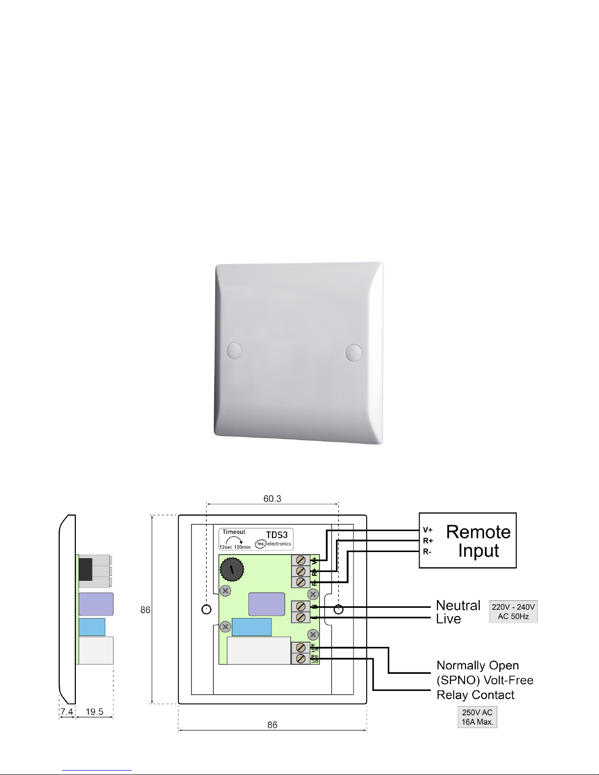
Figure 1 RTDS3
Figure 2 Typical wiring example and dimensions (in millimetres)
3
mselectronics.co.uk
Electrical Requirements
Before attempting to install the unit, ensure that the intended load and wiring arrangement
comply with the following requirements. Figure 2 shows a typical wiring example.
• 3-wire (live/neutral + volt-free switch) connection: The unit requires a permanent
live/neutral connection, and as such is not suitable for replacing an existing light switch
with no neutral conductor at the switch location. A volt-free relay output is provided,
which can be used to switch a load on the same mains supply (by connecting across
from L to LIVE IN, making LIVE OUT a switched live), or to provide a contact closure to
a separate load or control signal. There is no minimum load requirement.
Also available: RTDS2 (2-wire version) – Suitable for ‘inline’ connection with the load to
be switched (no neutral required), such as to replace a standard light switch. A minimum
load of 20W (per switch unit) applies; a load capacitor is required for smaller loads.
• Maximum load: The maximum load rating is 16A (4000W), however for high inrush
loads (such as most types of lighting), a lower limit applies: see Technical Specication.
• Remote Input: The unit is operated by momentary contact closures across the R+/R-
terminals (see Figure 2) according to the operating sequence (see Operation). At least
one appropriate switch or relay must be connected in accordance with the Remote Input
Wiring section. All wiring must be rated for mains voltages, and relay operation must
conform to the specied timings (see Technical Specication).
The remote input connections are referenced to the mains supply of the unit and are therefore not
safe to touch when the unit is powered. All switches and cables must be rated for mains voltages.
!
 Loading...