

Page 1

E827
energy saving controls
Product Guide
Setback Thermostat
E827/24V
with Timeout
today, tomorrow and in the future
mselectronics.co.uk
Page 2
Product Overview
The E827 offers an accurate, high quality and contemporary solution to tamperproof temperature
control with the added benet of an energy-saving automatic setback feature.
Utilising a high accuracy temperature sensor and high power output relay, the E827 controls room
heating via its voltage-free switched output to maintain the room temperature at one of two different
selectable levels.
The setback mode (frost / background temperature) will continuously regulate the room to a selected
temperature below the setpoint, helping to achieve energy savings when the room is unoccupied as
well as providing an acceptable minimum room temperature and frost protection.
The setpoint (higher room temperature / boost) temperature level may be activated by pressing the
touch-sensitive pushbutton once the room becomes occupied and the temperature is required to be
maintained at a higher level. The red LED on the front of the device indicates this mode is active.
After a pre-selected time period in the boost mode, the thermostat will automatically switch to the
setback mode until the pushbutton is again pressed.
Product Wiring
1. IMPORTANT: ensure all electrical connections are isolated before commencing any work on the
unit.
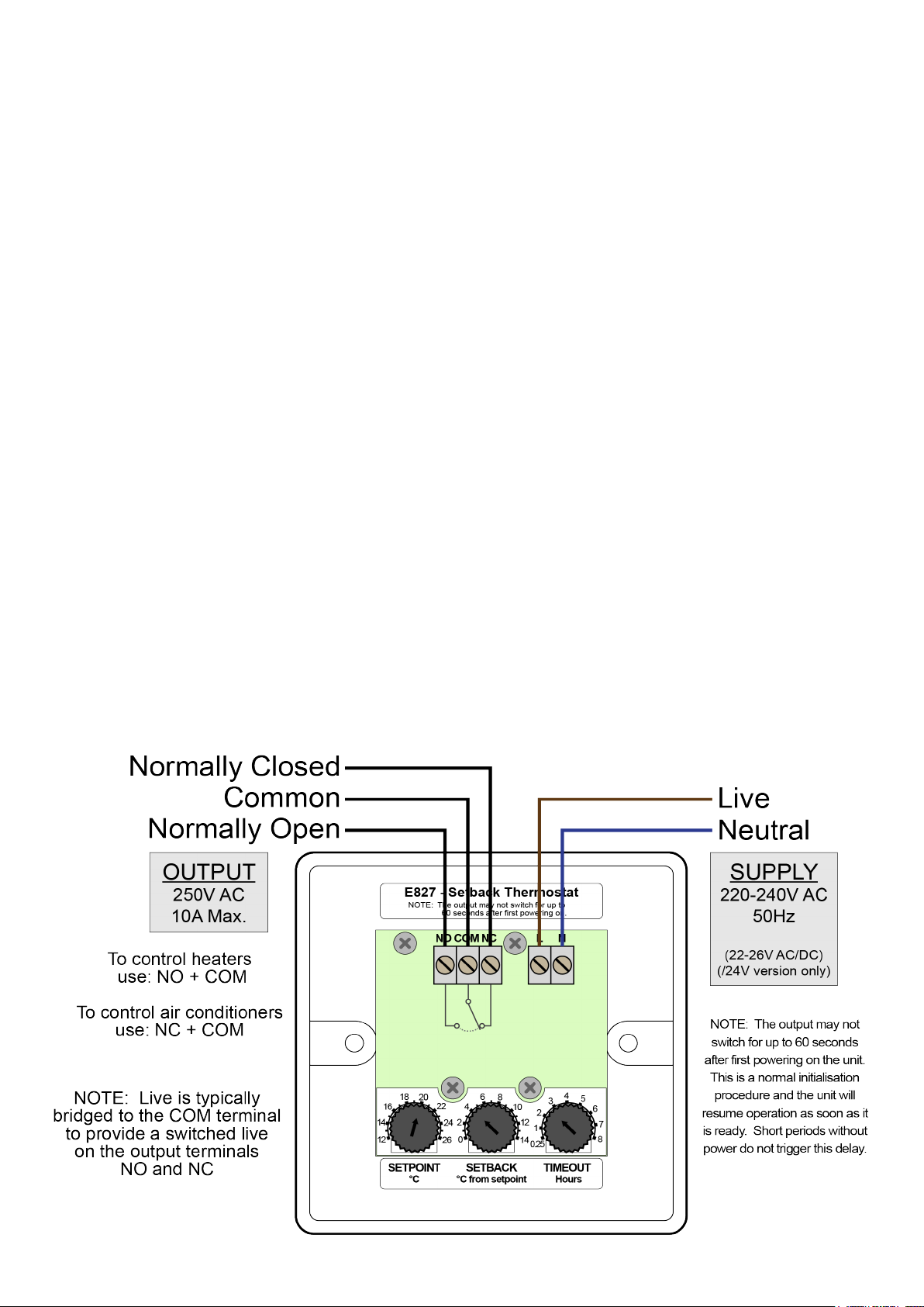
2. Power to the thermostat is provided via the Live and Neutral input terminals labelled “L” and “N”
(230V AC, 50Hz). On the 24 volt product variant (“/24V”) the same terminals are used (24V AC
3. or DC) and are not polarity sensitive.
4. A voltage-free changeover relay output capable of switching loads of up to 10A, 250V AC (resistive)
is provided by the thermostat. Connect to your application in an appropriate manner given the
following:
• The Common “COM” terminal is connected to the Normally Open “NO” terminal when the
sensed room temperature is below the selected temperature.
• Conversely, the “COM” terminal is connected to the Normally Closed “NC” terminal when the
sensed room temperature is above the selected temperature.
Issue 1.0
2
Page 3

Installation
1. IMPORTANT: ensure all electrical connections are isolated before commencing any work on the
unit.
2. The unit is designed to be mounted in any single-gang British Standard pattress box (surface or
ush mounted) which has a minimum internal depth of 20mm.
3. Ensure best-practices are used when choosing a location for the thermostat so that optimal
thermostatic control is achieved. Do not mount near drafts, heaters, radiators, air conditioners,
in direct sunlight or any other place where the sensed room temperature may be unnaturally
inuenced. A good mounting height is typically between 1m and 2m from the oor.
4. Connect the wiring as shown in the diagram (or any suitably appropriate form) via the screwterminals. Make sure to choose the correct output terminals that are suitable to your application.
5. Adjust the internal thumbwheels to suit the desired operational requirements (see below).
6. Afx the thermostat to the pattress box using the supplied M3.5 raised-countersunk screws then
nally insert the screw-caps for a neat nish.
7. The screw caps may be removed without damage using a sticky putty such as blu-tack.
Operation
1. IMPORTANT: ensure all electrical connections are isolated before commencing any work on the
unit.
2. Adjust the “SETPOINT” dial to the temperature the room is to be maintained at when the boost
mode is activated via the pushbutton (typically 21ºC).
3. Adjust the “SETBACK” dial to the temperature required below the setpoint when in setback mode
(typically 3°C to 6°C). NOTE: The setback temperature is subtracted from the setpoint. It is NOT
an absolute temperature.
4. Adjust the “TIMEOUT” to the number of minutes/hours that the boost mode should last for.
5. Example set-up:
SETPOINT set to 21ºC, SETBACK set to 4ºC, TIMEOUT set to 2 hours:
BOOST mode (RED led is ON)
The room temperature will be maintained at 21°C
After 2 hours (or the pushbutton is pressed) the unit will switch to SETBACK mode
SETBACK mode (RED led is OFF)
The room temperature will be maintained at 21 - 4 = 17°C
The pushbutton may be pressed to switch to BOOST mode
Technical Specication
Power supply:
Output switch rating: 10A, 250V AC 50Hz (resistive)
Output switch type: Changeover relay (volt-free)
Temperature setpoint: +12°C to +26°C
Temperature differential: Fixed at 1°C (+/- 0.5°C)
Temperature setback: 0°C to 14°C below the setpoint
Timeout period: 15 minutes to 8 hours
Sensor accuracy: ±0.2°C
Sensor drift: 0.15°C over 5 years
Guarantee: 5 Years
Weight: 88g
Dimensions: 86mm x 86mm x 26mm
220V - 240V AC 50Hz (live/neutral)
22V - 26V AC or DC (“/24V” variant only)
3Issue 1.0
Page 4

IMPORTANT INSTALLATION NOTICE
The installation of this product should be carried out in accordance with the latest IEE wiring
regulations and all wiring completed by a qualified electrician.
Technical Support
For further help or information on this and the other products in the MS Electronics range
visit www.mselectronics.co.uk or call 0333 666 1176.
Alternatively, email techsupport@mselectronics.co.uk
Additional copies of this product guide can be downloaded from our website.
Product Warranty
MS Electronics guarantees all their products against manufacturing defects for
5 years from the purchase date. If your product is found to be faulty, MS Electronics will,
at their discretion, repair or replace the product free of charge.
Note
Any modification or damage to the outer casing of the product, as well as any
damage to the product due to abuse or incorrect wiring may invalidate the guarantee.
energy saving controls
e: info@mselectronics.co.uk
t: 0333 666 1176 f: 0333 666 1436
mselectronics.co.uk
Follow us on twitter: @mselec
MS Electronics reserves the right to alter or change this specification without prior notice.
 Loading...