


Product Guide
E314
E314/24V
today, tomorrow and in the future
mselectronics.co.uk
Programmable Extension Timer
with Delay
energy saving controls
2
Issue 3.0
Product Overview
The E314 is a single-shot extension timer designed to control plant equipment such as heating, lighting or air-conditioning
systems outside of normal occupancy hours. A voltage-free changeover relay output capable of switching loads of up to 16A,
250V AC is activated for a congurable Extension time period after the congurable Delay period has elapsed. This enables
equipment to be automatically activated at the correct time in the future without the user being present, also bypassing
dicult reprogramming procedures often encountered when used in conjunction with conventional control equipment. The
E314 is an extremely user-friendly device with touch-sensitive pushbuttons, LED displays and fully adjustable timings,
providing simple yet powerful control of devices outside of occupancy hours.
Eective energy control and benecial time-management of personnel is obtained through the fully congurable “Delay” and
“Extension” periods. The Delay period is adjustable from 0.5 hours to 99 hours (steps of 0.5 hours up to 9.5, then steps of
1 hour thereafter) and the “Extension” period is adjustable from 1 to 9 hours (steps of 1 hour). Maximum limits for both the
Delay and Extension times can be programmed, ensuring the end-user cannot generate delays or extensions longer than the
authorised user allows.
When not in use, the extension timer enters a power-saving standby mode in an eort to reduce its energy usage.
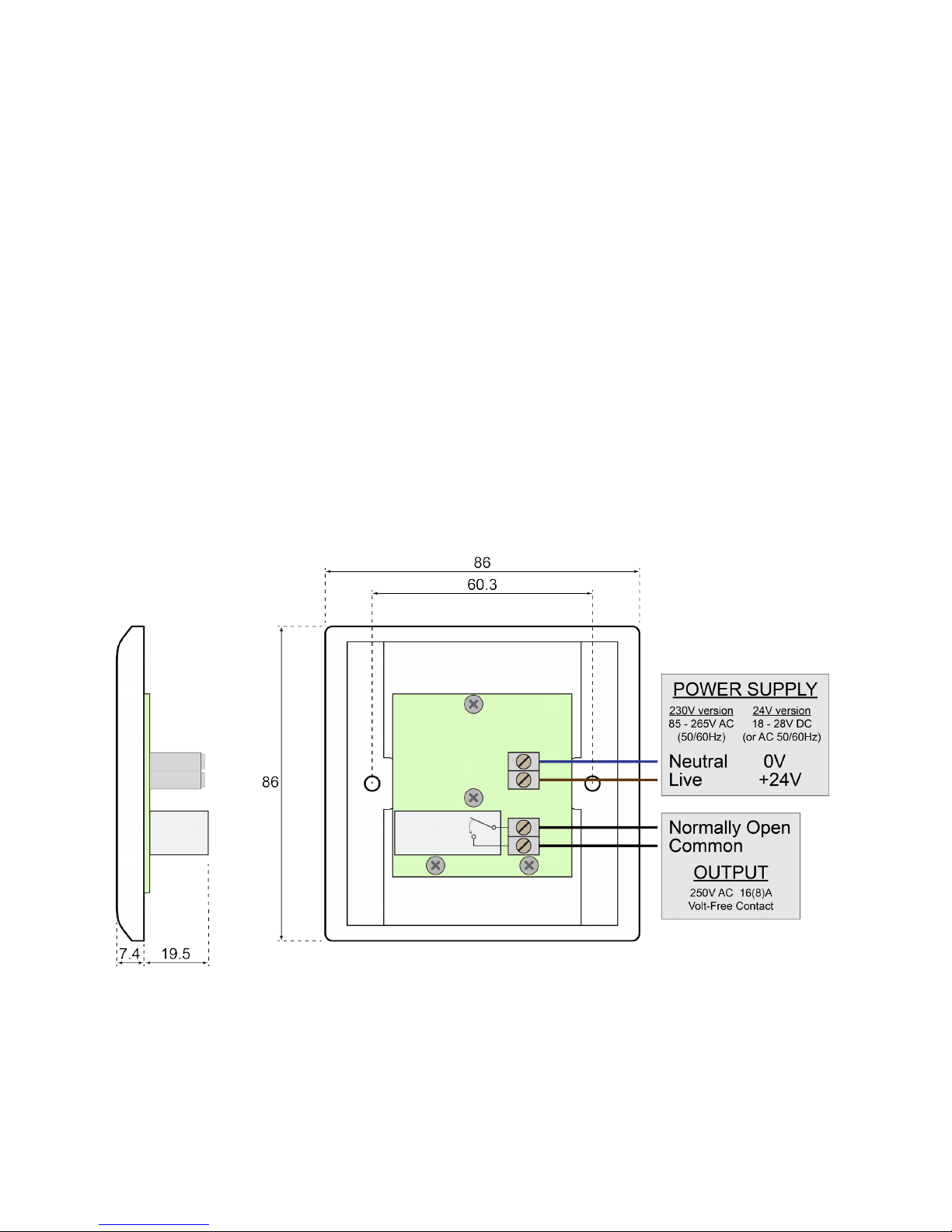
Product Wiring
IMPORTANT: ensure all electrical connections are isolated before commencing any work on the unit.
1. Power to the extension timer is provided via the Live and Neutral input terminals labelled “L” and “N” on the product. It
is universally compatible with all worldwide mains power (85 - 265V AC, 50 - 60Hz). The 24V version accepts a wide
input range of 18V to 28V DC or AC (50/60Hz).
2. A voltage-free relay contact output capable of switching loads of up to 16(8)A 250V AC is provided by the extension timer.
• The Common “COM” terminal is connected to the Normally Open “NO” terminal during the extension period and is
disconnected at all other times.
Installation
1. IMPORTANT: ensure all electrical connections are isolated before commencing any work on the unit.
2. The E314 is designed to be mounted in a 20mm (or deeper) single-gang UK pattress box.
3. Connect the wiring to the terminal blocks on the extension timer as shown in Figure 1 (or any suitably appropriate form).
Make sure to choose the correct output terminals that are suitable to your application.
4. Secure the E314 into the pattress box using the two supplied M3.5 screws.
5. Fit the supplied screw covers to complete the installation.
• To remove the screw covers without damage, use an adhesive putty such as blu-tack as an aid.
Figure 1 Typical wiring example

3
Issue 3.0
Operation
Operation Modes
The E314 has 3 operating modes:
Standby: Power-saving mode where the dimmed LED displays show “0” on all digits.
Setting Up: Bright LED displays with the currently selected display blinking. This mode is used to choose
the desired Delay and Extension periods.
Running: Bright LED displays show the times remaining with the “Running” LED blinking. The “On” LED
illuminates when the output is active. Once the extension is complete the unit will revert
back to Standby mode.
Conguration: The “Running” and “On” LEDs blink alternately. This mode is used to congure the maximum
Delay and Extension period that the user will be allowed to select up to in the Setting Up
mode.
Selecting and Running an Extension
1. Press the “Increase” button to wake up the timer from Standby mode (enters Setting Up mode).
• The “Delay” display will start blinking to show it is selected.
2. Repeatedly press or hold down the “Increase” button to count up to the required Delay period.
3. Press the “Select/Start” button to move to the Extension display.
• The “Extension” display will start blinking to show it is selected.
4. Repeatedly press or hold down the “Increase” button to count up to the required Extension period.
5. Hold down the “Select/Start” button to start the extension running (enters Running mode).
• The “Running” LED will start blinking to show the extension is running.
6. To cancel an active extension at any time, hold down the “Select/Start” button.
• The unit will go back to the Setting Up mode.
Notes - Setting Up mode
1. If no button is pressed for 8 seconds, the unit will revert back to Standby mode.
2. If you accidentally go past the desired delay or extension period, you must either:
• Keep going until the period reaches the end and wraps back to the beginning.
• Wait for the unit to automatically go back into Standby by not pressing any button for 8 seconds.
3. An extension can be started immediately by selecting a delay of zero.
Conguring the Maximum Selectable Delay and Extension
1. NOTE: Conguration mode can only be entered once within the rst 2 minutes of the extension timer powering up.
2. From the Standby mode, hold down the “Select/Start” button.
• The “Running” and “On” LEDs will start blinking alternately to show that Conguration mode has been entered. The
displays will also show the current maximum delay and extension periods that were previously stored.
3. Select the desired maximum delay and extension periods by using the “Increase” and “Select/Start” buttons, the same as
described in steps 2, 3 and 4 of Selecting and Running an Extension.
4. Hold down the “Select/Start” button to save the new maximum delay and extension periods.
• The new values will be permanently stored and the unit will revert back to Standby mode. Conguration mode
cannot be entered again unless the unit is power-cycled.
Notes - Conguration Mode
1. If you accidentally select the Conguration mode and do not want to save any changes, you must either:
• Overwrite the maximums with the same original value.
• Wait 2 minutes without pressing any buttons so the unit automatically reverts back to Standby mode. All changes
will be lost.
• Reset the extension timer by powering it o and on again. All changes will be lost.
Technical Specication
Power supply:
230V version: 85 - 265V AC 50/60Hz (worldwide universal)
24V version: 18 - 28V DC or AC (50/60Hz)
Output switch rating: 16(8)A, 250V AC
Output switch type: SPNO relay (volt-free)
Output terminals: 3.3mm2 solid/stranded wire, rising clamp
Operating temperature: -10°C to +40°C
Suitable for: 20mm (or deeper) single-gang UK pattress or back box
Ingress protection rating: IP40
Guarantee: 5 Years
Weight: 95g
Dimensions: 86mm x 86mm x 26.9mm

e: info@mselectronics.co.uk
t: 0333 666 1176 f: 0333 666 1436
mselectronics.co.uk
Follow us on twitter: @mselec
MS Electronics reserves the right to alter or change this specification without prior notice.
IMPORTANT INSTALLATION NOTICE
The installation of this product should be carried out in accordance with the latest IEE wiring
regulations and all wiring completed by a qualified electrician.
Technical Support
For further help or information on this and the other products in the MS Electronics range
visit www.mselectronics.co.uk or call 0333 666 1176.
Alternatively, email techsupport@mselectronics.co.uk
Additional copies of this product guide can be downloaded from our website.
Product Warranty
MS Electronics guarantees all their products against manufacturing defects for
5 years from the purchase date. If your product is found to be faulty, MS Electronics will,
at their discretion, repair or replace the product free of charge.
Note
Any modification or damage to the outer casing of the product, as well as any
damage to the product due to abuse or incorrect wiring may invalidate the guarantee.
energy saving controls
 Loading...