


Product Guide
DH-1/24V
today, tomorrow and in the future
mselectronics.co.uk
Duct Humidistat
energy saving controls
2
Issue 1.0
Product Overview
The DH-1/24V duct humidistat offers a calibration-free, high accuracy and high quality solution to
humidity control of duct airow in heating, ventilation and air conditioning (HVAC) systems. The unit
is powered from a 24V AC or DC supply and mounts directly on to the outside of the ductwork, with
the probe projecting into the duct.
The DH-1/24V regulates to a fully adjustable relative humidity set-point between 5% and 95%,
combined with an adjustable relative humidity hysteresis (differential) of anything between 1% and
10%.
Product Wiring
1. IMPORTANT: ensure all electrical connections are isolated before commencing any work on the
unit.
2. Power to the humidistat is provided via the 24V AC/DC input terminals. No specic polarity is
necessary on the power connections.
3. A voltage-free changeover relay output capable of switching loads of up to 10A, 250V AC
(resistive) is provided by the humidistat. Connect to your application in an appropriate manner
given the following:
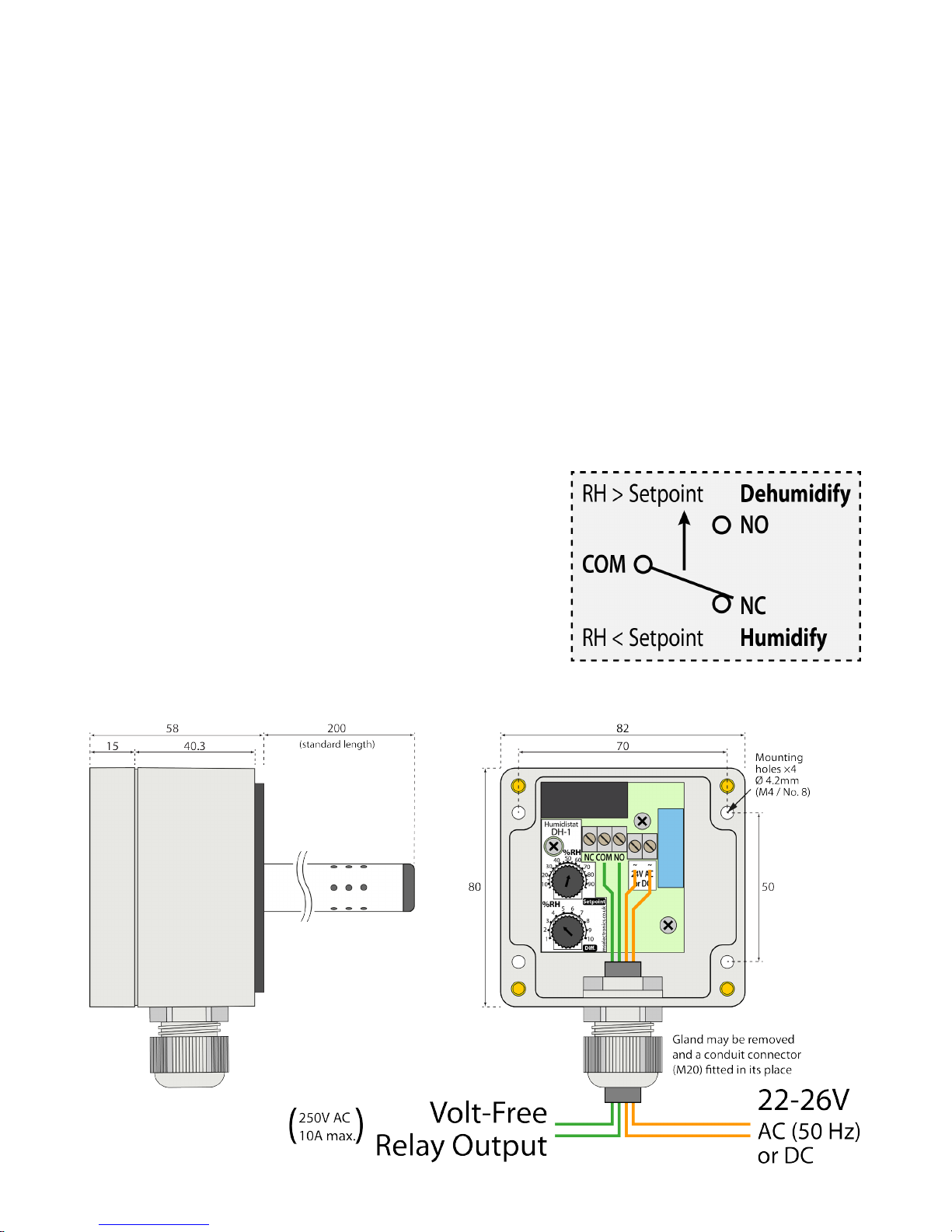
• The Common “COM” terminal is connected to the
Normally Open “NO” terminal when the sensed
relative humidity is above the “Setpoint” humidity.
(Use to control dehumidication equipment,
including air conditioners.)
• Conversely, the “COM” terminal is connected to the
Normally Closed “NC” terminal when the relative
humidity is sensed to be below the “Setpoint”
humidity. (Use to control humidication equipment.)
Figure 1 Typical wiring example (for dehumidication)

3Issue 1.0
Installation
1. Identify a suitable location on the ductwork exterior, preferably where the duct air is cleanest
(after ltration elements). Mark and drill a 16mm (minimum) diameter hole in the duct through
which the probe will enter. Any existing hole of up to 25mm is also suitable.
2. Remove the lid of the unit and place the probe through the hole, with the unit at to the
ductwork and centred in the hole. Mark the four mounting positions (indicated in Figure 1).
3. Drill appropriate pilot holes, and secure the unit to the duct with suitable self-tapping screws.
4. Adjust the internal controls to suit the installation operational requirements (see below).
5. Wiring to the unit should run through the preinstalled cable gland. Alternatively, if a direct
connection to electrical conduit is desired, a suitable conduit connector may be tted.
If using gland: For cable outer diameters of 5 to 7.5mm, use the gland as provided. For larger
cables (up to 13mm), remove the outer nut of the gland, withdraw the rubber insert, separate
the two parts and reinsert just the outer ring. The other part may be discarded.
If using conduit: Remove the cable gland by holding the internal locknut steady and
unscrewing the outer part. Fit an appropriate conduit connector (with M20 thread) in its place.
6. Connect the wiring to the terminal blocks on the humidistat as shown in Figure 1 (or in any
suitably appropriate form). Make sure to choose the correct output terminals that are suitable to
your application.
7. Tighten the cable gland or conduit connector onto the outer sheath of the cable.
8. Replace the lid and securely tighten the screws.
Operation
1. Adjust the “Setpoint” dial to the relative humidity the duct air is to be regulated to.
2. Set the “Differential” to the total relative humidity swing either side of the “Setpoint” that the duct
air humidity is required to keep within.
3. Example of a typical set-up:
Setpoint set to 55% RH, Differential set to 4% RH.
The unit will maintain the relative humidity between 53% RH and 57% RH.
4. In clean airow, the unit should require no maintenance. If necessary, the unit may be released
from the duct and any accumulated debris blown or vacuumed from the probe grille.
Technical Specication
Power supply: 22V - 26V AC (50Hz) or DC
Output switch rating: 10A, 250V AC 50Hz (resistive)
Output switch type: Changeover relay (volt-free)
Cable entry:
Pre-tted M20 gland, for 5 to 13mm dia. round
cable (remove reducer insert for >7.5mm).
May be exchanged for a M20 conduit connector
Humidity control: 5% RH to 95% RH
Humidity differential: 1% RH to 10% RH
Sensor accuracy: +/- 3% RH
Sensor drift:
+/- 1.2% RH over 5 years (no calibration
required)
Probe length (standard): 200mm (sensing element 178mm from base)
Guarantee: 5 Years
Weight: 210g
Dimensions (with standard probe): 109mm x 82mm x 258mm
Ensure the electrical supply to the unit is isolated before making any adjustments.
!
All electrical installation and maintenance must be carried out by qualied personnel
in accordance with the current edition of the IET Wiring Regulations (BS7671).
!

e: info@mselectronics.co.uk
t: 0333 666 1176 f: 0333 666 1436
mselectronics.co.uk
Follow us on twitter: @mselec
MS Electronics reserves the right to alter or change this specification without prior notice.
energy saving controls
IMPORTANT INSTALLATION NOTICE
The installation of this product should be carried out in accordance with the latest IET wiring
regulations and all wiring completed by a qualified electrician.
Technical Support
For further help or information on this and the other products in the MS Electronics range
visit www.mselectronics.co.uk or call 0333 666 1176.
Alternatively, email techsupport@mselectronics.co.uk
Additional copies of this product guide can be downloaded from our website.
Product Warranty
MS Electronics guarantees all their products against manufacturing defects for
5 years from the purchase date. If your product is found to be faulty, MS Electronics will,
at their discretion, repair or replace the product free of charge.
Note
Any modification or damage to the outer casing of the product, as well as any
damage to the product due to abuse or incorrect wiring may invalidate the guarantee.
 Loading...