

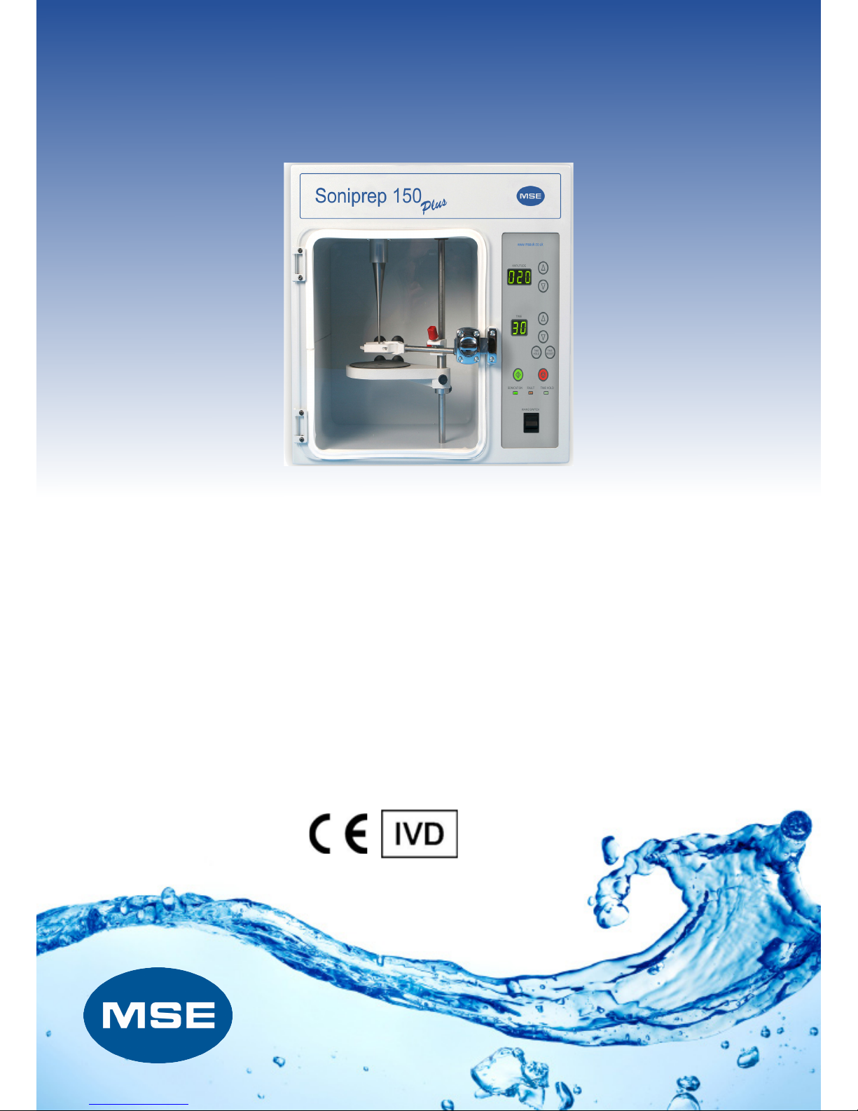
Soniprep 150 Plus
Ultrasonic Disintegrator
User Manual
Please read this before use

MSE (UK) LTD
Health and Safety at Work
MSE (UK) Ltd is required under the 1974 Health and Safety at Work Act and other UK legislation as
designers, manufacturers, suppliers and exporters of articles for use at work to ensure that, as far as is
reasonably practicable, articles which we design, produce, supply or import are safe and without risk to
health.
We are required to provide information on the safety and handling precautions to be observed when
installing, operating, maintaining and servicing our products. Such advice is contained in this manual.
We are also obliged to update this information should circumstances change and to operate a system to
this end.
We should also like to point out, however that you as users have an important responsibility in the
provision and maintenance of safe working practices and conditions.
Accordingly, we draw the following matters to your attention:
1. This apparatus should only be used as intended and within its design parameters by suitably
qualified and trained personnel who have read and understood the relevant sections of this
manual.
2. This manual should be readily available to such personnel at all times.
3. In addition to that which is written in the manual, normal common-sense safety precautions must
be taken at all times to avoid the possibility of accidents. Particular care is required when working
with apparatus at high temperature or pressure.
4. Installation, maintenance, repairs and servicing should only be carried out by an MSE (UK) Ltd
approved engineer, and connection to electrical supplies should only be carried out by suitably
trained personnel.
TECHNICAL SUPPORT, WARRANTY SERVICE AND MAINTENANCE
UK customers; if you are in any doubt whatsoever regarding the correct use of this apparatus, or if you
require any technical data or assistance, please contact the MSE (UK) Ltd Technical Support Department
at:
Telephone
E-mail:
MSE Centrifuges Ltd
11 Browning Road
Heathfield
East Sussex
TN21 8DB
Website:
+44 1435 517 000
sales@msecentrifuges.com w
ww.msecentrifuges.com
OVERSEAS CUSTOMERS: Should contact their local MSE (UK) Ltd distributor.
ELECTRICITY SUPPLIES: Voltage and frequency
MSE (UK) Ltd electrical apparatus is offered and labelled for one or for a choice of two or more voltage
ranges and, where necessary, different frequencies of mains supply. MSE (UK) Ltd does not accept any
responsibility for the operation of any such apparatus should it be connected to electricity supplies which
are normally outside, or vary outside, the stated voltage and frequency values for which it is designed, nor
for any consequential loss, damage or injury, howsoever caused.

Please dispose of centrifuge carefully!
MSE adheres to the WEEE (Waste Electrical and Electronic Equipment) directive, which
ensures that all electrical equipment is disposed of carefully with consideration to the
environment. As a responsible manufacturer of quality laboratory equipment, MSE will
recycle your equipment once its life expires and therefore reduce the amount of waste
electrical equipment that is sent to landfill.
When you would like to dispose of your equipment, please contact us on +44 (0) 870 609
4097 to arrange a collection.
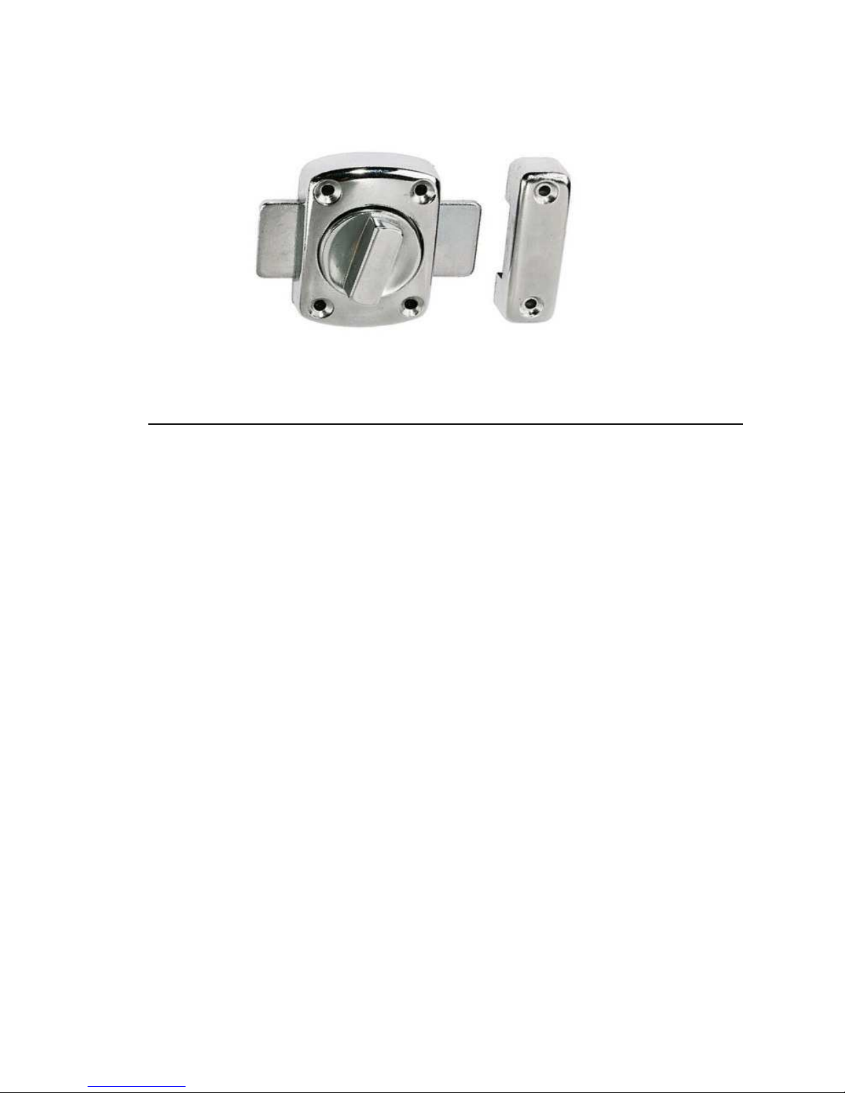
Read This Before Use!
THIS MACHINE HAS BEEN FITTED WITH A NEW THUMB TURN LOCK.
PLEASE OPERATE THIS MACHINE ONLY WHEN THE DOOR IS LOCKED AND THE
LATCH IS FULLY ENGAGED
TO ENSURE THE DOOR IS FULLY LATCHED, TURN THE THUMB WHEEL FULLY
CLOCKWISE TILL THE FLATS ON THE LOCK ARE SITTING HORIZONTALLY
THIS STOPS ANY SOUND WAVES FROM LEAVING THE SOUND PROOFED CHAMBER
PLEASE TURN THE SONIFICATION OFF BEFORE OPENING THE DOOR.
MSE Centrifuges Limited
11 Browning Road, Heathfield, East Sussex. UK TN21 8DB.
Sales: +44 1435 517 000 Service: +44 1435 517 005
Email: sales@msecentrifuges.com
msecentrifuges.com
Type of device:
Product name:
Model numbers:
Ultrasonic Disintegrator
Soniprep 150 Plus
SONIPREP-EXP-BUNDLE SONIPREP-9.5-BUNDLE
SONIPREP-19-BUNDLE
EC guidelines and standards:
73/23/EEC, BS EN 61010-1, BS EN 61010-2-020
89/336/EEC, 92/31/EEC, 93/68/EEC, BS EN 61000-6-1, BS EN 61000-3-2, BS EN 610003-3, BS EN 55011
98/37/EG, BS EN ISO 12100-1, BS EN ISO 12100-2
Declaration
I declare as the authorised representative, the above information in relation to
the supply/manufacture of this product is in conformity with the stated standards
and other related documents following the provisions of EEC Directives.
Signature of authorised representative and date:
1st April 2018
B Sturgess
EC DECLARATION OF CONFORMITY
According to
ISO 17050
-
1, ISO/IEC 17050
-
2
Dr B Sturgess
1st August 2018

Thank you for buying an MSE Soniprep 150 Plus. Please
read this operating manual before using your Soniprep; it
will provide you and your colleagues with useful
information on all aspects of the equipment.
As our customer, we should like to ensure that you
are totally satisfied at all times. Do not hesitate to
contact our team.
Email - sales@msecentrifuges.com
Web - msecentrifuges.com/contactus
Your views are very important to us

MSE (UK) LTD PRODUCT WARRANTY
Terms and Conditions
We hope that you do not have the need to use the extensive warranty cover that MSE (UK) Ltd extends
to you. However should you have a problem, our prompt response is greatly helped if you have filled in
and posted the pre-paid Warranty Registration Card supplied with your new equipment.
MSE Centrifuges Ltd gives a one-year warranty from the date of delivery. During this period,
component parts proven to be defective in materials or workmanship will be repaired or
replaced at our expense. Installation, commissioning and calibration are not covered by this
warranty agreement. The MSE Centrifuges Ltd approved service agent must be contacted for
warranty determination and direction prior to any work being carried out.
These warranties are only applicable to new products and not second hand nor refurbished
products even if repaired by MSE Centrifuges Ltd. Any such products are covered by separate
warranty terms and conditions which will be made available on request.
Replacement or repair of component parts or equipment under this warranty shall not extend the
warranty to either the equipment or the component part beyond the original one year warranty
period unless agreed in writing by MSE Centrifuges Ltd.
The above warranties are extended to the original purchaser upon full invoice payment. A purchase
receipt or other proof of purchase may be required before warranty service will be performed. These
warranties only cover failures due to defective workmanship which occur during the normal operation of
the product by the original purchaser, and not failures which result from accident, misuse, abuse, neglect,
mishandling, misapplication, alteration, faulty installation, electrical power fluctuations, dust, or other
environmental extremes, modification or service other than by an approved service agent or following the
written authority of the manufacturer, or damage that is attributable to acts of God. Expendable items
such as motor brushes, door seals, lid seals, ‘O’ rings or lamps are excluded.
MSE Centrifuges Ltd, or its approved service agent, reserves the right to repair defective
equipment on the premises of the customer, or at a service station, at the sole discretion of MSE
Centrifuges Ltd or their approved agent. In the event of return to an approved service centre the
customer is responsible for the safe packaging of the instrument and notification to the service
centre. Neither MSE Centrifuges Ltd nor its agents are responsible for any damage occurring during
shipment.
Specification and Material Changes: MSE Centrifuges Ltd reserves the right to supply our latest and
improved models at time of shipment.
Taxes: The prices quoted do not include any taxes imposed by the State or Country in which
the purchase was made.
Installation: Installation of all equipment shall be at the expense of the purchaser unless stated
otherwise. Access to the site, and the provision of required utilities e.g. power, water and
drainage to suitable connections, will be the responsibility of the purchaser, and at the purchaser's
expense.
Limitation of liability: In no event, whether as a result of breach of contract or warranty, shall MSE
Centrifuges Ltd be liable for any consequential or incidental damages including, but not limited to,
loss of profit or revenues, loss of use of the equipment or any associated equipment, down time
costs, costs of substitute equipment, costs of labour, costs due to delays or claims of
purchaser's own customers for such damages. The purchaser agrees to indemnify MSE Centrifuges
Ltd and to hold them harmless from any and all liability, claims, demands, actions, suits, expenses
or costs, including attorney's fees relating to such consequential or incidental damages.
All expressed and implied warranties, including the warranties of merchantable quality and fitness
for a particular purpose are limited to the application period of one year.
Validity: Legal rights vary from country to country and states within countries, so some or all of
the exclusions or limitations listed above may not apply, but if any part of these conditions shall be
found to be unenforceable it shall not affect the validity or enforceability of the remainder of the
conditions.

ELECTRICITY SUPPLY
Before connecting this apparatus to the electricity supply, check the information given
on the apparatus rating plate and ensure that:
A) Your supply is single phase AC (alternating current) of the stated frequency with
the neutral nominally at earth potential.
B) Your supply voltage is within the stated range.
C) The current rating is within the capacity of your supply outlet.
D) Your plug or electricity supply circuit is fitted with a suitable fuse.
Fuse Rating 220v-240v 110v-120v
5 amp See note 100V - 120V
WARNING! This apparatus must be earthed
Your Soniprep is supplied with an IEC mains lead that will be suitable for your local
Electricity supply
NOTE: 100v-120v installations to comply with National and State Wiring Codes
IMPORTANT: Consult an electrician if in doubt or if your supply system has any
of the following:
No earth.
Reversible plugs.
Supply and return leads that are both above earth potential.
NOTE: Do not touch plug pins within two seconds of plug removal from socket.

CONTENTS 9
CONTENTS
1. INTRODUCTION..................................................................................................10
1.1 General Description .............................................................................. 10
1.2 Control Panel Description .................................................................... 12
2. INSTALLATION...................................................................................................14
2.1 Power Supply and Fuses...................................................................... 14
3. PROBES..............................................................................................................15
3.1 Description and Function..................................................................... 15
3.2 Exponential Microprobe ....................................................................... 15
3.3 Fitting a probe to the Transducer ........................................................ 15
3.4 Position of the probe in the liquid for treatment ................................ 15
3.5 Probe Maintenance ............................................................................... 16
3.6 Testing Probe Performance ................................................................. 17
4. PROCESSING SAMPLES...................................................................................18
4.1 Vessels for Samples ............................................................................. 18
4.2 Basic Processing .................................................................................. 18
4.3 Batch Treatment Vessel........................................................................ 19
4.4 Meter Flow Vessel................................................................................. 19
4.5 Continuous Flow Vessel....................................................................... 19
5. OPERATING INSTRUCTIONS............................................................................20
5.1 Manual Control...................................................................................... 20
5.2 Timer Control......................................................................................... 20
5.3 Optional Process Timer Unit (230V units only).................................. 20
5.4 Operating Instructions.......................................................................... 20
6. CLEANING...........................................................................................................22
7. FAULT FINDING..................................................................................................22
7.1 General................................................................................................... 22
7.2 Fault conditions could be:- .................................................................. 22
7.3 Loose Probe........................................................................................... 22
7.4 Fatigued Probe Or Coupling Stud........................................................ 22
8. SPECIFICATIONS...............................................................................................23
8.1 Specification For Soniprep................................................................... 23
8.2 Specification For Process Timer ......................................................... 23
9. OPTIONAL ACCESSORIES FOR THE SONIPREP 150 PLUS.........................24
10. PRODUCT DISPOSAL - ISO 14001 COMPLIANCE..........................................24

INTRODUCTION 10
1. INTRODUCTION
The Soniprep 150 Plus Ultrasonic Disintegrator is a self-contained unit
designed for convenient tabletop operation. It incorporates an acoustic cabinet,
which reduces externally audible noise and ultrasound to a safe level. A
transparent door allows observation of the sample during sonication. The
apparatus is factory adjusted to the user's electrical supply voltage and
frequency.
1.1 General Description
The generator is a solid-state transistor amplifier, which provides electrical
energy, at an output frequency of 23 KHz, to a high efficiency piezo-electric
transducer, which converts the electrical energy to mechanical energy. The
transducer, mounted in the top of the disintegrator chamber, transmits
ultrasound by high frequency vibrations via a titanium alloy probe. There is a
choice of three probes, which screw into the transducer head and transmit
energy of approximate amplitude for any specific application. Each probe is
designed to operate at a nominal frequency of 23 KHz concentrating the
resultant ultrasonic energy, as required.
Table 1 Probe Details
Description Tip Diameter Transformation Ratio
Large Probe Assy.
(solid)
19mm(3/4’) 3.8:1
Small Probe Assy.
(solid)
9.5mm(3/8’) 5.5:1
Exponential
Microprobe
3mm(1/8’) 7:1
The disintegrator is designed to cope with different requirements and will
ensure that there is the maximum possible acoustic energy at the tip for the
probe. Once the output level has been selected it is continuously maintained by
the automatic feed back from the transducer. A meter, calibrated in microns,
allows the amplitude to be monitored continuously.
An adjustable table and a retort clamp are mounted on a rod within the
chamber. The specimen to be treated is contained in a suitable tube clamped in
position or in a vessel placed on the adjustable table.

INTRODUCTION 11
Front
Rear
VESSEL
CONNECTION
(INLET/OUTLET)
PROCESS TIMER
CONNECTION
(POWER)
MAINS
CONNECTION
FUSES
WATT METER
CONNECTION
PROCESS TIMER
CONNECTION
(CONTROL)
PROBE
SAMPLE CLAMP
PLATFORM
CONTROL
PANEL
DOOR LOCK

INTRODUCTION 12
Control Panel Description
The control panel is situated on the right hand side of the unit. A brief
description of their individual functions follows:
Amplitude Meter - The meter is calibrated in microns and monitors the probe
amplitude, that is, the actual movement peak-to-peak that is taking place at the
transducer/probe interface. Multiplying the meter indication by the
transformation ratio of the particular probe in use (See Table 1) allows actual
movement of the probe tip to be determined.
Power Control –The UP and DOWN arrows next to the Amplitude meter
window are used to increase or decrease the amplitude level displayed on the
amplitude meter. (In order to set the amplitude level the green start button
has to be pressed first)
This control permits stepped selection of power output to the transducer,
providing an accurate and reproducible amplitude setting for the particular
probe in use.
Timer - This is a 99 minute timing unit which can be used for timed runs or in a
continous running mode. At the end of a timed run the Soniprep will turn itself
off and the timer will reset itself to the last selected time. The timed run will start
when the GREEN start button is pressed.
The timed run required is selected by the UP and DOWN arrows next to the
TIME window. Set the time required and press START (green switch). The
sonication lamp will be illuminated, ultra sonication will commence and the timer
will start run-down to zero. When the time selected has expired, the unit will
switch off automatically and the sonication lamp will go off.
Time Hold Switch - When selected and the start (GREEN) button is pressed
the unit will operate continuously and the minutes of operation will count up.
Sonication Lamp - When the lamp is illuminated, it indicates that the power is
through to the transducer and there fore to the probe.

INTRODUCTION 13
Control Panel
AMPLITUDE
INCREASE
AMPLITUDE
DECREASE
POWER OFF POWER ON
TIME
DECREASE
TIME
INCREASE

INSTALLATION 14
1.2 Power Supply and Fuses
When the equipment is first received, the voltage selector switch has been
set by the manufacturer and is in the correct positioned to suit your local power
supply.
Two anti-surge fuses are factory fitted in the holders located beneath the mains
inlet connection socket.
Location of the Instrument and Electrical Connections
Place the Soniprep 150 Plus on a suitable table or bench and ensure that at the
rear of the instrument is at least 50mm (2’) away from the wall to allow
adequate air circulation.

PROCESSING SAMPLES 15
2. PROBES
2.1 Description and Function
The probe is a resonant element used for the transmission of vibrating
mechanical energy from the transducer to the sample. The prime purpose of
the probe is to increase the transducer amplitude to a usable level or, to select
the acoustic power transfer. Ideally, material used for such probes should have
good acoustic properties, high fatigue strength, low acoustic loss and density. It
is essential that it should also be corrosion and erosion resistant and relatively
inert to the materials being sonicated. The material that possesses all these
qualities is titanium alloy and it is from this material that probes available for use
with the disintegrator, are manufactured.
Note: Probes are specially designed to suit the Soniprep 150 Plus models
and are tuned to 23 KHz.
2.2 Exponential Microprobe
This probe has been specifically designed for the treatment of small quantities
of sample, up to 5ml. It should, preferably, be used with the 20ml tube and
sealing cap but any other suitably sized tube may be employed.
2.3 Fitting a probe to the Transducer
Clean the mating surfaces of the probe and transducer with a soft cloth.
Before fitting the probe, screw the coupling stud into the transducer
approximately 10mm leaving approximately 10mm protruding. Screw the probe
onto the stud in the transducer head, by hand. Then tighten firmly using the
tommy bar provided through hole in the probe. In the case of the exponential
probe use the spanner provided.
It is important that the probe is clamped securely to the transducer, as failure to
do so will result in a large power loss and an irritating high-pitched noise.
NOTE: The coupling stud is a relatively loose fit in both the transducer
and the probe to ensure that the contact surfaces are allowed to mate
perfectly. An extremely small
smear of silicone grease on the probe head
will facilitate surface mating.
2.4 Position of the probe in the liquid for treatment
When maximum power is necessary for a difficult application, the probe tip
should be immersed into the solution to an optimum depth.
As a guide, for 50ml sample down to 10ml sample, the best position for the
probe tip is 1cm below the surface of the sample. If the sample is less than
10ml, the best position for the probe tip should be found by trial and error.
Excessive depth and also the viscosity of the solution will cause the power to be
damped, which will be evident by a lower indication on the amplitude meter.
Conversely, if the probe tip is insufficiently below the surface, there will be a
tendency to generate foam in the solution or to cause scattering of droplets out
of the vessel. This is especially so when using high amplification. If the solution
foams, there will be a distinct change in sound, i.e. virtually unloaded and little
energy is being transferred to the solution.

PROCESSING SAMPLES 16
Sometimes, when the solution is thoroughly aerated, the usual process noise
from the beaker or test tube will stop, i.e. no buzz or vibration will be heard.
Again, this is because there is little transfer of energy. When these conditions
occur, turn the power off for a few seconds and set the probe deeper. Gradually
increase the power and the solution will de-gas. The lower the power setting,
the smaller will be the quantity that may be processed without foaming the
solution. Do not allow the probe to come too close to, or make contact with, the
sides or bottom of glass containers as powdered glass may be formed in the
solution, or breakage may occur. Plastic tubes are more resistant to failure
during sonication, but the insulation properties of plastic may make it difficult to
keep the sample cool.
CAUTION
Please bear in mind that sonication can weaken glass tubes. It is
therefore, advisable that glass tubes used in sonication are not
subsequently centrifuged at high speed as failure of the tube may result.
2.5 Probe Maintenance
In use the probe will erode by the action of cavitation in the liquid. This
dissolution of the metal from the tip of the probe, which occurs, with any metal
during use at high sound intensities is, however, reduced to a minimum by the
use of titanium. The erosion shows itself in concentric rings on the radiating
face. An eroded surface transfers energy less efficiently into the liquid than a
smooth one because of the formation of a zone of cavitation adjacent to the
surface. Energy not transferred into the liquid medium will tend to heat the end
of the probe. Furthermore, erosion continues at an accelerated rate on the
probe tip surface, which is already pitted, thus reducing the useful life of the
probe. For these reasons the tip of the probe should be polished smooth by
means of a very fine emery cloth on a flat surface, but note the following two
cautions.
CAUTION:
a) Probes WEAR OUT, although probes may be polished / reground, the
length of the probe must not be shortened by more than 2mm. PROBES
SHOULD BE REPLACED ANNUALLY OR AS REQUIRED.
b) The transducer/probe mating surfaces must not be cleaned with a non
abrasive cleaner. Should the end require polishing, ONLY A LIQUID NON
ABRASIVE POLISH should be used.
The Soniprep Plus has a red Fault light on the control panel
that will come on when the probe is required to be changed

PROCESSING SAMPLES 17
2.6 Testing Probe Performance
The following test should be carried out so that users may monitor the
performance of each probe.
Measure the temperature rise obtained at maximum power after 5 minutes with
the following volumes of chilled water (i.e. below 10°C).
Probe Volume of Chilled Water
Exponential 15ml
9.5mm 50ml
19mm 100ml
A temperature rise of approximately 35°C should be obtained. If the rise is not
obtainable, the probe or the transducer is at fault. To pinpoint the part of the
system, which is faulty, repeat the test with an UNUSED probe. If you still do
not obtain a temperature rise of approximately 35°C, then contact the service
centre at the address inside the front cover.
The service centre will give you more advice.

PROCESSING SAMPLES 18
3. PROCESSING SAMPLES
3.1 Vessels for Samples
NOTE:
Minimum Volume - Volumes of less than 1ml may be treated with the
exponential microprobe. The sample should be held in a micro tube.
Maximum Volume - A maximum of 100ml may be treated at any one time.
However, larger volumes may be processed by using the treatment vessels. It
is preferable to use a narrow vessel rather than a wide one. Twice the volume
in a narrow vessel takes a shorter time to process than the same volume in a
wider vessel. Twice the volume or concentration takes twice as long to process.
Materials that are particularly resistant to ultrasonic energy, however, should be
processed in the smallest area practicable. Since the energy radiates from the
probe tip in the shape of a cone, the more confined the sample under the tip
the better the results. A narrow, relatively short test tube is also called for when
processing small quantities, say of the order of 4ml. The probe tip should
displace as much liquid as possible to force a long liquid height or ‘head’ above
the vibrating tip. This prevents foaming or whipping the solution out of the test
tube. A wide beaker is not normally suitable.
There is considerable evidence that the shape of the container has great
influence on the rate of release of soluble protein or the efficiency of the cellular
breakage. This is probably more the function of mixing than anything else, since
the individual components are not directly exposed to the action of the probe tip
for more than a second or two. If the volume is very large, then individual cells
are not in the area of cavitation activity for a sufficient period of time. The probe
tip should be below the surface of the liquid by approximately 13mm (1/2’) and
should not be too far from the bottom of the vessel l(again approximately
13mm). If the tip is not satisfactorily immersed, a considerable quantity of air
may be trapped in the solution thus dissipating the power delivered and not
allowing it to be transmitted to the solution. As there is sufficient force
generated by the Soniprep 150 Plus to fracture or shatter glass, the probe tip
must not be allowed to come in contact with, or come close to, the bottom of
the vessel.
3.2 Basic Processing
Test tubes of 20ml and 100ml nominal capacity are available for certain
applications. In addition to these, cooled treatment vessels are available for use
when it is important that the media being treated should be subjected to
minimal temperature rise.
A range of rubber sealing caps are available for all tubes and cooled treatment
vessels. The probe is inserted through the sealing cap which fits over the mouth
of the vessel, or tube, and provides an air tight seal.
For ease of manipulation and to effect the best possible seal, the edge of the
hole in the sealing cap should be lightly smeared with silicone grease. When
using sealing caps, ensure the tube is securely clamped to prevent downward
movement of the tube and consequent disengagement from the probe.

PROCESSING SAMPLES 19
When fitting sealing caps, the air pressure which may have built up can be
released by lifting the edge of the cap slightly. The caps are manufactured from
a material which is suitable for autoclaving.
When treating samples in any of the test tubes the temperature of the
suspension will rise, especially if the quantities of the material being treated are
small. To avoid this temperature rise, immerse the tube containing the medium
in a beaker containing crushed ice or a suitable cooling mixture. The beaker
can be placed on the adjustable platform and the vessel containing medium
held in the laboratory clamp. However, if the medium being treated is
particularly sensitive to temperature, then one of the cooled treatment vessels
described in sections 3.3, 3.3 and 3.4 should be used.
3.3 Batch Treatment Vessel
This consists of an inner chamber to contain up to 50ml of sample to be
treated, surrounded by a cooling jacket through which a suitable cooling liquid
(e.g. iced water or alcohol) can be circulated.
3.4 Continuous Flow Vessel
This is available for the treatment of even larger volumes where the required
disintegration time is relatively short. This vessel has both inlet and outlet tubes
to the inner chamber which allows the sample to be passed continuously
through at a measured flow rate as disintegration takes place.
Apertures are provided in the back of the ultrasonic cabinet so that the
liquid feed-lines can be passed through to the treatment vessels and
permit sonication with the cabinet door closed.

OPERATING INSTRUCTIONS 20
4. OPERATING INSTRUCTIONS
Misuses include: a) Impeding air flow.
b) Incorrect positioning of the probes with respect to the
transducer (see section 2.4).
c) Lack of probe maintenance (see section 2.5).
d) Probe in liquid (foaming)
4.1 Manual Control
a) Plug the 3 pin plug into the power outlet. Switch the green supply rocker
switch to its ‘ON’ position (its inner LED will illuminate).
b) Open the door, place the vessel containing the sample to be treated on the
Table or if a test tube, clamp in position and set up for sonication as
required. Close the door.
c) Press the Time Hold switch, the GREEN sonication lamp will illuminate and
sonication can commence once amplification is set and the Start button is
pressed.
d) If not set, then select amplitude level required.
e) After sonication is complete, switch the supply rocker switch to its ’OFF’
position.
4.2 Timer Control
a) Carry out instructions in section 4.1 a) and b).
b) Set time, 1 to 10 minutes, by pressing the UP or DOWN arrows.
Immediately the Start button is pressed the green sonication lamp will light
up, and after the time selected on the timer has run out, sonication will
cease and the green lamp will go off.
4.3 Optional Process Timer Unit (230V units only)
a) Place the Process timer Unit on top of the Soniprep.
b) Connect the two cables from the process timer - one terminating in a three-
pin plug (power) and the other terminating in a five-pin plug (control) - to the
corresponding sockets on the rear of the Soniprep.
4.4 Operating Instructions
a) Set up the desired operating conditions on the digital switches of the
process timer unit.
Ensure the Soniprep power is ON and that the amplitude is set as required.
c) Switch on the process timer mains switch. The green mains lamp will
illuminate.
d) Press the start switch push-button on the process timer unit.
The Soniprep will now operate under the control of the process timer unit.
If it is required to stop the process during sonication, press the stop button on
he process timer unit. Sonication will cease and the timer will reset for the next
cycle.

OPERATING INSTRUCTIONS 21
USE THE CONTROL SWITCHES ON THE PROCESS TIMER ONLY WHILST
THE PROCESS TIMER IS PLUGGED INTO THE SONIPREP
APART FROM TURNING THE SONIPREPON AT THE MAINS AND SETTING
UP THE AMPLITUDE, THE PROCESS TIMER SHOULD BE USED TO
CONTROL THE SONIPREP ONLY.
( Please do not open the door whilst using the Process Timer because in
this mode the door interlock switch is not in circuit. )
Process Timer
THE WATTAGE METER (Part Number 46222-5020)
The wattage meter can be plugged into the back of the Soniprep to the 3 pin
din socket in order to see the power being dissipated into the sample.
The display on the meter shows the watts of power that the sample is receiving.
The display will show small up and down movements as the amplitude does
vary slightly depending on the peak or the trough of the sign wave.

CLEANING AND FAULT FINDING 22
Use a damp cloth for cleaning outside.
If internal chamber etc. requires disinfecting the following fluids may be used:
TERMINEX 2 (Available from Arrow Chemicals Ltd)
VIRKON (Available from Antec International)
These cleaning agents if used as instructed by the manufacturer should not be
harmful to this product, or accessories supplied for use with this product.
5. FAULT FINDING
5.1 General
Faults occurring during use can usually be traced to the titanium probe as this is
subject to high mechanical stresses. Possible faults are loss of effectiveness in
operation, a high-pitched screeching from the transducer unit and also a
wavering indication on the amplitude meter. The amplitude meter can be used
to monitor performance. Any fault condition will show as a loss of amplitude.
5.2 Fault conditions could be:
a) Probe insufficiently tightened.
b) Probe/Transducer faces not clean.
c) Probe too short.
d) Probe fatigued.
e) Transducer fault.
5.3 Loose Probe
A change in the pitch of the noise from the transducer (usually accompanied by
an indication on the amplitude meter) is a sure sign that the probe has worked
loose. Uncouple the probe from the transducer and clean both surfaces with a
soft cloth. Re-couple the probe to the transducer.
5.4 Fatigued Probe or Coupling Stud
Similar symptoms will be evident if the probe is fatigued, although this fault
would be detected at an earlier stage as there would have been difficulty in
obtaining satisfactory amplitude. However, to check that the fault is actually in
the probe, remove it and the coupling stud from the transducer and test the
probe's performance as described in section 2.6. If the probe is faulty, fit a new
one.
Again, symptoms common to a loose, or fatigued, probe may indicate a
fatigued stud. If necessary, renew it.
7.5 If your Soniprep has the door lock with a built in microswitch, ensure that the
door lock is fully turned in a clockwise direction. If the door lock is not fully
turned, it will not engage with the microswitch and your Soniprep will not
operate.

SPECIFICATIONS 23
6. SPECIFICATIONS
6.1 Specification for Soniprep
MSS150.CX3.5 MSS150.CX3.1
HEIGHT (mm) 450 450
WIDTH (mm) 470 470
DEPTH (mm) 258 258
WEIGHT (Kg) 18.7 18.7
PROBE FREQUENCY (KHz)
23 23
VOLTAGE (volts) 220/240 120
MAINS FREQUENCY (Hz) 50/60 60
FUSES (anti-surge) 2amp 4amp
MAX. NOISE LEVEL (dB)
WITH DOOR CLOSED
68 68
MAX. NOISE LEVEL (dB)
WITH DOOR OPEN
86 86
6.2 Specification for Process Timer
46222.5019
HEIGHT (mm) 73
WIDTH (mm) 255
DEPTH (mm) 228
WEIGHT (Kg) 1.2
VOLTAGE (volts) 230
MAINS FREQUENCY (Hz) 50
FUSES (anti-surge)
F250µA

SPECIFICATIONS 24
7. OPTIONAL ACCESSORIES FOR THE SONIPREP 150 PLUS
PART
NUMBER
DESCRIPTION
46222-5019 Process Timer Unit
38121-114A Exponential Microprobe, end diameter 3mm
38121-1154 Solid Probe, end diameter 9.5mm
38121-1169 Solid Probe, end diameter 19mm
48535-1011 Batch Treatment Vessel
46222-5020 Wattage meter
48533-1016 Continuous Flow Vessel
34411-8163 20ml Heat Resisting Test Tube
34411-8222 50ml Heat Resisting Test Tube
34411-8237 100ml Heat Resisting Test Tube
34431-4168 Rubber Sealing Cap for 20ml and 50ml tubes for use with probe
38121-115
34431-8136 Rubber Sealing Cap for 20ml and 50ml tubes for use with probe
38121-116
34431-4094 Rubber Sealing Cap for 20ml and 50ml tubes for use with
exponential probe 38121-114
34431-4115 Rubber Sealing Cap for all cooled treatment vessels or 100ml
tube - probe 38121-114
34431-4187 Rubber Sealing Cap for all cooled treatment vessels or 100ml
tube - probe 38121-116
34431-4172 Rubber Sealing Cap for all cooled treatment vessels or 100ml
tube - probe 38121-115

11 Browning Road, Heatheld, East Sussex. UK. TN21 8DB
Sales: +44 (0) 1435 517 000
Service : +44 (0) 1435 517 005
www.msecentrifuges.com
Distributor
MICROCENTAUR R
Refrigerated Micro Centrifuge
Maximum speed 18000 rpm
Maximum RCF 24270 xg
Maximum Volume 24 x 2/1.5ml
HARRIER
General Purpose Centrifuge
Ambient and Refrigerated
Swing Out / Fixed Angle / Microplate
Maximum speed 18000 rpm
Maximum RCF 30065 xg
Maximum Volume 4 x 250ml
Meet the rest of the family
Brand new generaon of centrifuges
 Loading...