

Page 1

USER’S MANUAL
PSE-608R(I)/616R(I)/624R
Power Source Equipment
Page 2

User’s Manual
PSE-608R(I)/616R(I)/624R
2
Contents
1. Introduction...........................................................................
Features................................................................................................
Package Contents.................................................................................
2. Hardware Description...........................................................
Physical Dimension...............................................................................
Front Panel............................................................................................
LED Indicators.......................................................................................
Rear Panel............................................................................................
Power On..............................................................................................
Network Application...............................................................................
RJ-45 Remote Control Port...................................................................
3. Software Utility Installation..................................................
4. GUI Management...................................................................
Display and Illustration..........................................................................
System Login........................................................................................
Modify Password…...............................................................................
Edit Station TCP/IP...............................................................................
Edit Remote PoE IP.............................................................................
GUI Connect All....................................................................................
Single Station Connect/Disconnect……………………………………..
Station and Status Window Select …...................................................
Edit Port Name…………………………………………………………….
Configuration.........................................................................................
Factory Setting…………........................................................................
Board Status…………………………………………………………………
Port Status…………………………………………………………………...
GUI Version………………………………………………………………….
GUI Disconnect All…………..…………………………………………......
File Open and Save…………………………………………………………
5. Technical Specification........................................................
3
3
4
4
4
4
5
5
6
6
7
14
15
15
16
17
18
20
21
23
24
25
26
27
29
30
31
32
33
34
Page 3

User’s Manual
PSE-608R(I)/616R(I)/624R
3
1. Introduction
The PSE-608R(I)/616R(I)/624R PoE midspan, support 8/16/24 ports respectively in a
10/100/1000BaseTx Ethernet network, over TIA/EIA-568 Category 5/5e/6 cabling. DC
operating power, for data terminal units, is fed over data pairs of the cabling (4/5 and 7/8).
This allows greater flexibility in the locating of network devices and significantly decreasing
installation costs in many cases.
The PSE-608R(I)/616R(I)/624R follows the IEEE 802.3af/IEEE 802.3at and is completely
compatible with existing Ethernet switches and networked devices. Normally powers PDs
(Powered Devices) that are Power over Ethernet enabled or are equipped to receive power
over Ethernet. The PSE tests whether a networked device is PoE-capable, power is never
transmitted unless a Powered Device is at other end of the cable. It also continues to
monitor the channel. If the Powered Device does not draw a minimum current, because it
has been unplugged or physically turned off, the PSE shuts down the power to that port.
Devices that are not equipped to receive power over Ethernet may require an external
splitter in order to be powered. Contact Mstronic for such a splitter.
Features
8/16/24 port Power Sourcing Equipment ( power over Ethernet Hub)
Support 8/16/24 ports full load, max. 35W/port
AC input (100-240 VAC, 50/60 Hz)
IEEE802.3af/IEEE 802.3at compliance, Power over Ethernet Mid-Span mode
Remote power feeding of Ethernet terminals up to 100 meters
Auto detect PD, and support manual detect PD
Centralized power distribution for PoE powered Device (PD)
Independent overload and short-circuit protection per channel
Supports IEEE 802.3af/IEEE 802.3at non-standard device
Auto refresh port status and support Plug and Play feature for PD
Standard 19” or 23” rack mountable
DIY upgrade from 8 port to 16/24 port available
Remote manage up to 24 units via TCP/IP protocol
Isolated DC input available, can work with battery, non-interrupt performance.
Page 4
User’s Manual
PSE-608R(I)/616R(I)/624R
4
Package Contents
Unpack the contents of the PSE-608R(I)/616R(I)/624R and verify them against the
checklist below.
PSE-608R(I)/616R(I)/624R x 1
Power Cord x 1
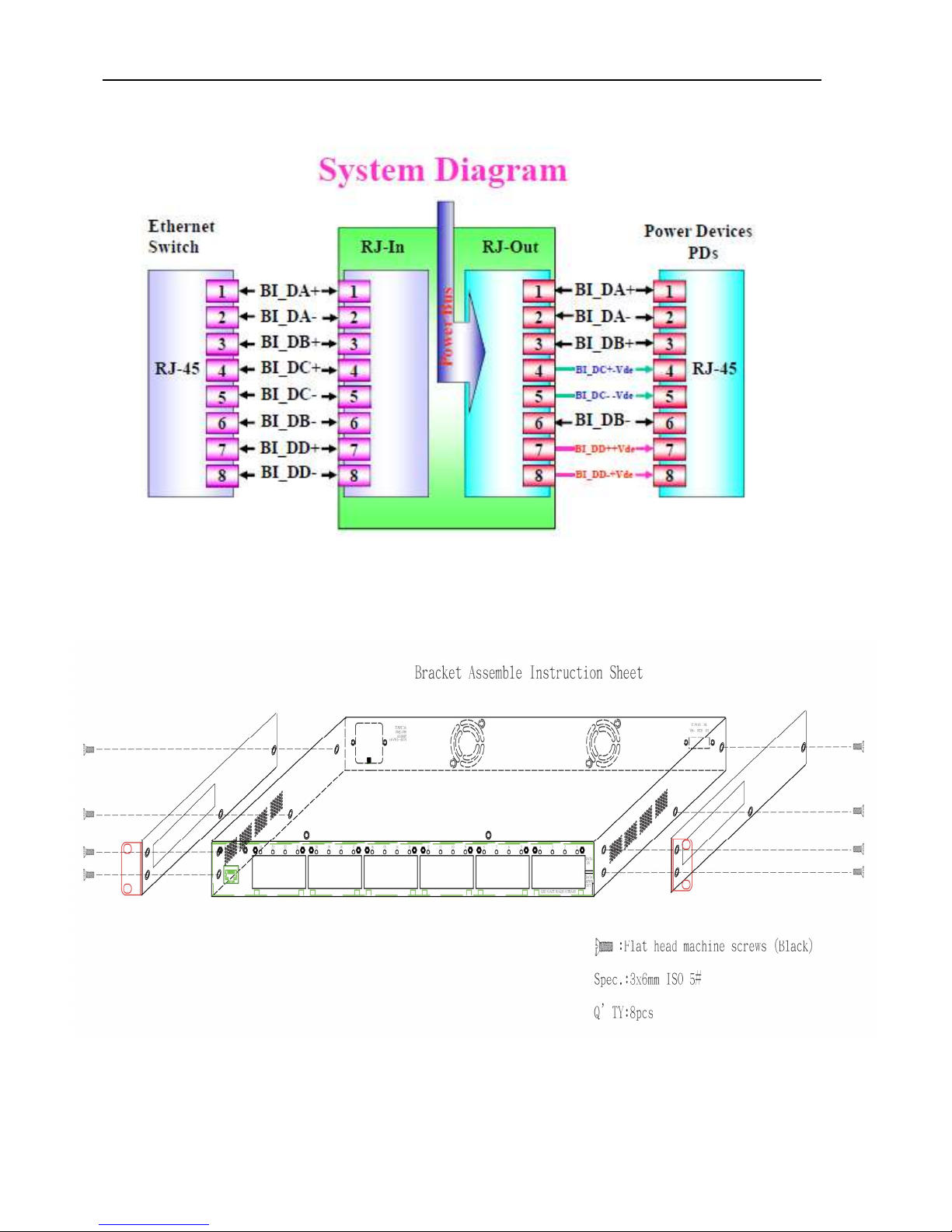
Bracket x 2 ( for 19” rack mounted)
CD-ROM x 1 (Software Utility + User Manual)
Compare the contents of your PSE-608R(I)/616R(I)/624R package with the standard
checklist above. If any item is missing or damaged, please contact your local dealer for
service.
2. Hardware Description
This Section mainly describes the hardware of the PSE-608R(I)/616R(I)/624R and gives a
physical and functional overview.
Physical Dimension
PSE-608/608RI/616R physical dimension is: 430mm x 290mm x 44mm (Lx W x H),
PSE-616RI/624R is 430mm x 400mm x 44mm (1U, 19” or 23” Rack mountable).
Front Panel
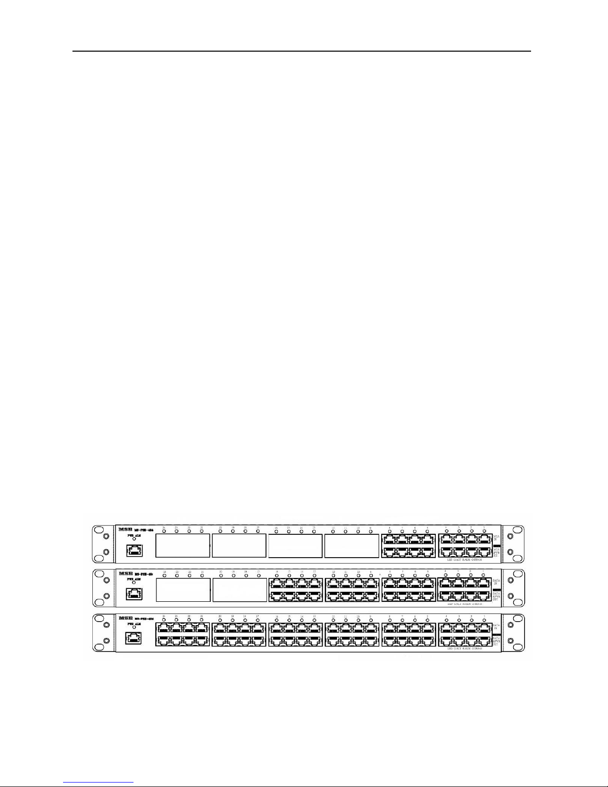
Figure 2-1. The Front panel of PSE-608R(I)/616R(I)/624R
The Front Panel of the PSE-608R(I)/616R(I)/624R consists of 8/16/24 x RJ-45 Ethernet
ports (data), 8/16/24 x RJ-45 PoE ports (data + power), 8/16/24 x LED port indicators, one
LED power indicator and one RJ-45 remote control port (include one LED).
Page 5

User’s Manual
PSE-608R(I)/616R(I)/624R
5
LED Indicators
The LED Indicators gives real-time information of systematic operation status. The
following table provides descriptions of LED status and their meaning.
LED Status Color Description
RJ45
On Green
A network device is
detected(10/100/1000 Mbps)
but no communication activity is
detected
Blinking Green
The Ethernet port is transmitting
to, or receiving package from
another device
Off -- No device is detected
Power
On Green Power feeding normally
On
Red
Power or fan alarm
Off -- Power off
Ports
On Green Power feeding
Blinking Orange Detecting
On Orange
The port has been shutdown
No power feeding
On Red
Alarm
No power feeding
Off --
Unknown device attached
No power feeding
Table 2-1. The Description of LED Indicators
Rear Panel
The AC inlet, DC input terminal, and 4 Ventilation fan are located at the rear panel. The
device will work with AC in the range 100-240V AC, 50-60Hz. Or work with DC
(-42~-57VDC for PSE-608R/616R/624R, 40V~60VDC for PSE-608RI/616RI)
Page 6

User’s Manual
PSE-608R(I)/616R(I)/624R
6
Power On
Connect the power cord to the power socket on the rear panel of the PSE. The other side
of power cord connects to the power outlet. The internal power supply of the PSE works
with voltage range of AC in the 100-240VAC, frequency 50~60Hz, or with voltage range of
DC in the -42~-57VDC (40~60V for PSE-608RI/616RI). Check the power indicator on the
front panel to see if power is properly supplied.
Network Application
The PSE can provide power to the PD that follow the IEEE 802.3af/IEEE802.3at standard
in the network. It can solve the problem of position limitation. The network device can be
installed in more appropriate position for better performance. The following figure is an
example of network application for PSE
Page 7
User’s Manual
PSE-608R(I)/616R(I)/624R
7
RJ-45 Remote Control Port
PSE-608R(I)/616R(I)/624R can remotely manage the PoE via the network. To manage
PSE-608R(I)/616R(I)/624R, you must to set the PSE-608R(I)/616R(I)/624R TCP/IP
parameter.
PSE-608R(I)/616R(I)/624R allowed you to use a standard Web-browser such as Microsoft
Internet Explorer or Mozila, to set the TCP/IP parameter.
Before you use the web interface to set the PoE TCP/IP, verify that
PSE-608R(I)/616R(I)/624R is properly installed on your network and PC on the network
can access PoE via the web-browser.
1. Verify that PC network interface card (NIC) is operational on the TCP/IP protocol.
2. Supply power to PSE608R/616R/624R.
3. Use RJ45 cable, connect PSE608R/616R/624R direct to your PC.
4. Make sure the PSE608R/616R/624R default IP is 192.168.1.10.
5. Set your PC IP to 192.168.1.2 or other IP address which is located in the 192.168.1.x
subnet.
6. Make sure the connector is OK (Ping 192.168.1.10 on the DOS mode).
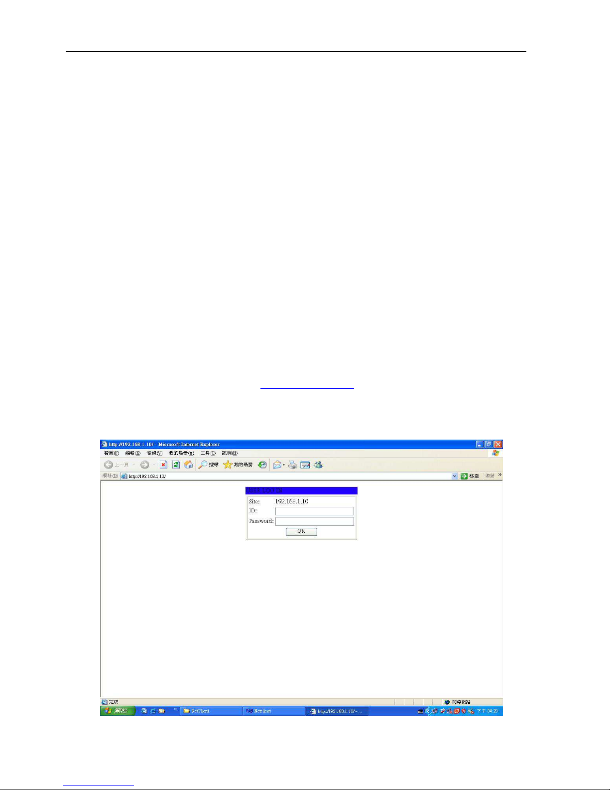
7. Start the web-browser and type http://192.168.1.10 (or used PoE IP setting icon in the
PoE management software).
8. The login in screen will appear next.
Page 8

User’s Manual
PSE-608R(I)/616R(I)/624R
8
9. Key in ID (user name) and password to enter PoE TCP/IP parameter setting.
Default ID and password is “admin” and “system”.
10. PSE-608R(I)/616R(I)/624R TCP/IP parameter has 4 pages interface (administrator
setting, TCP Mode, UDP Mode and UART). You must change the administrator & TCP
mode to fit your network.
Page 9
User’s Manual
PSE-608R(I)/616R(I)/624R
9
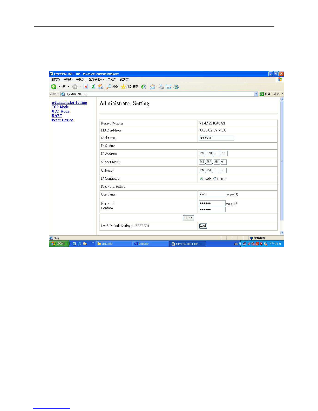
11. Administrator setting: you can assign nickname, IP setting, user name, password and
view system information.
Nickname: You can assign a name to the device.
IP Address: You must assign the IP address reserved by your network. The default IP is
192.168.1.10.
Subnet Mask: You can assign the subnet mask for the IP address. The default subnet
mask is 255.255.255.0.
Gateway: You can assign the gateway here. The default gateway is 192.168.1.1.
IP Configure: You must assign to Static for PoE serve operation. The default IP configure
is Static.
Username: You can assign new user name. The default setting is admin.
Password/Confirm: You can type in new password here. The default setting is system.
When you have finished the set up, click on Update to update your setting.
Page 10
User’s Manual
PSE-608R(I)/616R(I)/624R
10
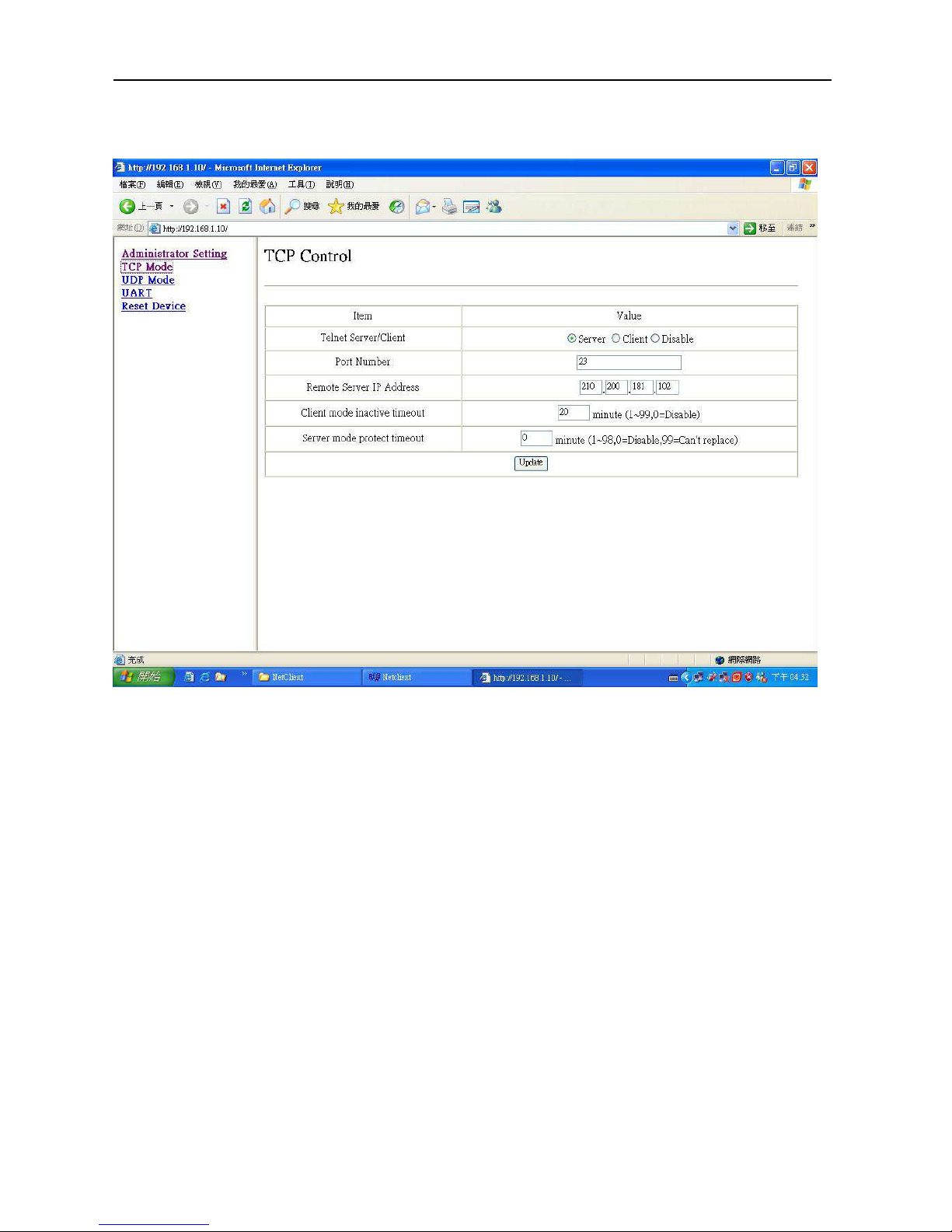
12. TCP Mode: You can update the TCP control parameter here.
Telnet Server/Client: Set to Server for PoE management operation.
Port Number: You can assign port number for TCP/IP operation. The default Port Number
is 23.
Remote Server IP Address: Unused.
Clint mode inactive timeout: Unused.
Server mode protect timeout: Set to 0(Disable) for normal operation.
When you have finished the set up, click on Update to update your setting.
PS: The PSE-608R(I)/616R(I)/624R don’t used in the Telnet terminal.
Page 11
User’s Manual
PSE-608R(I)/616R(I)/624R
11
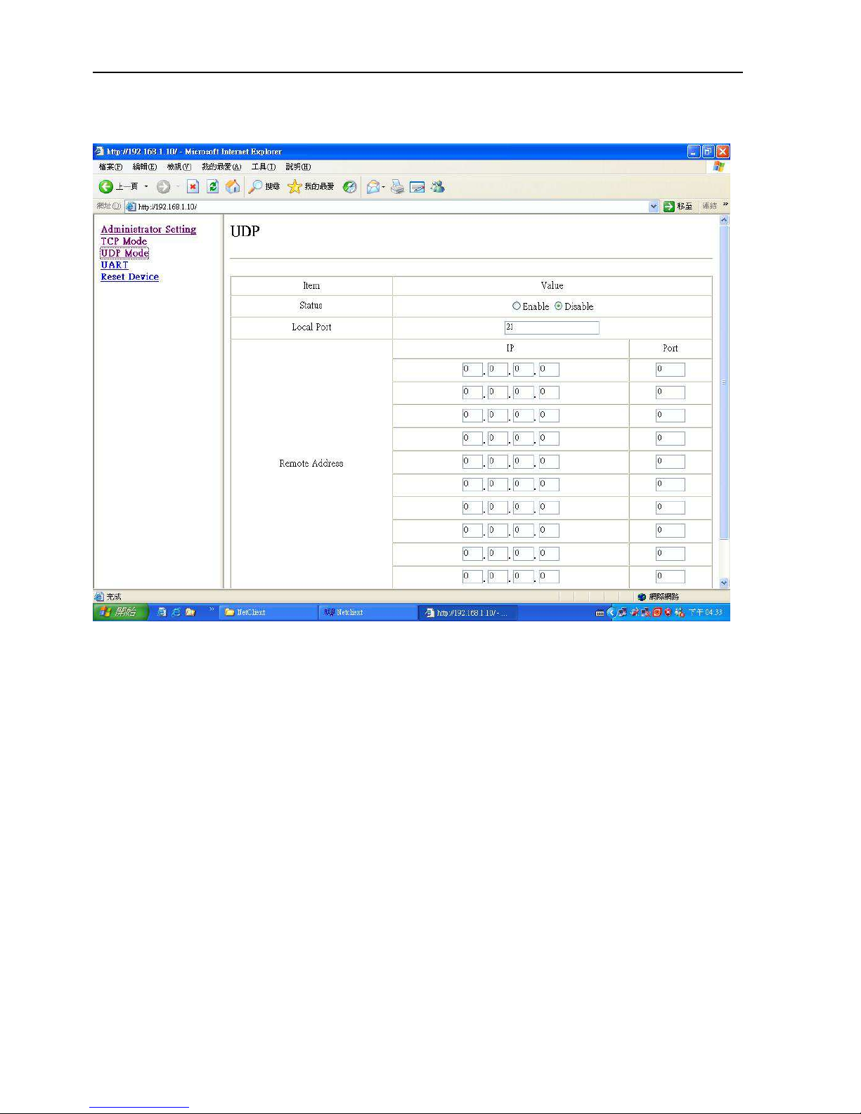
13. UDP Mode: This mode is not used in the PoE application.
Page 12
User’s Manual
PSE-608R(I)/616R(I)/624R
12
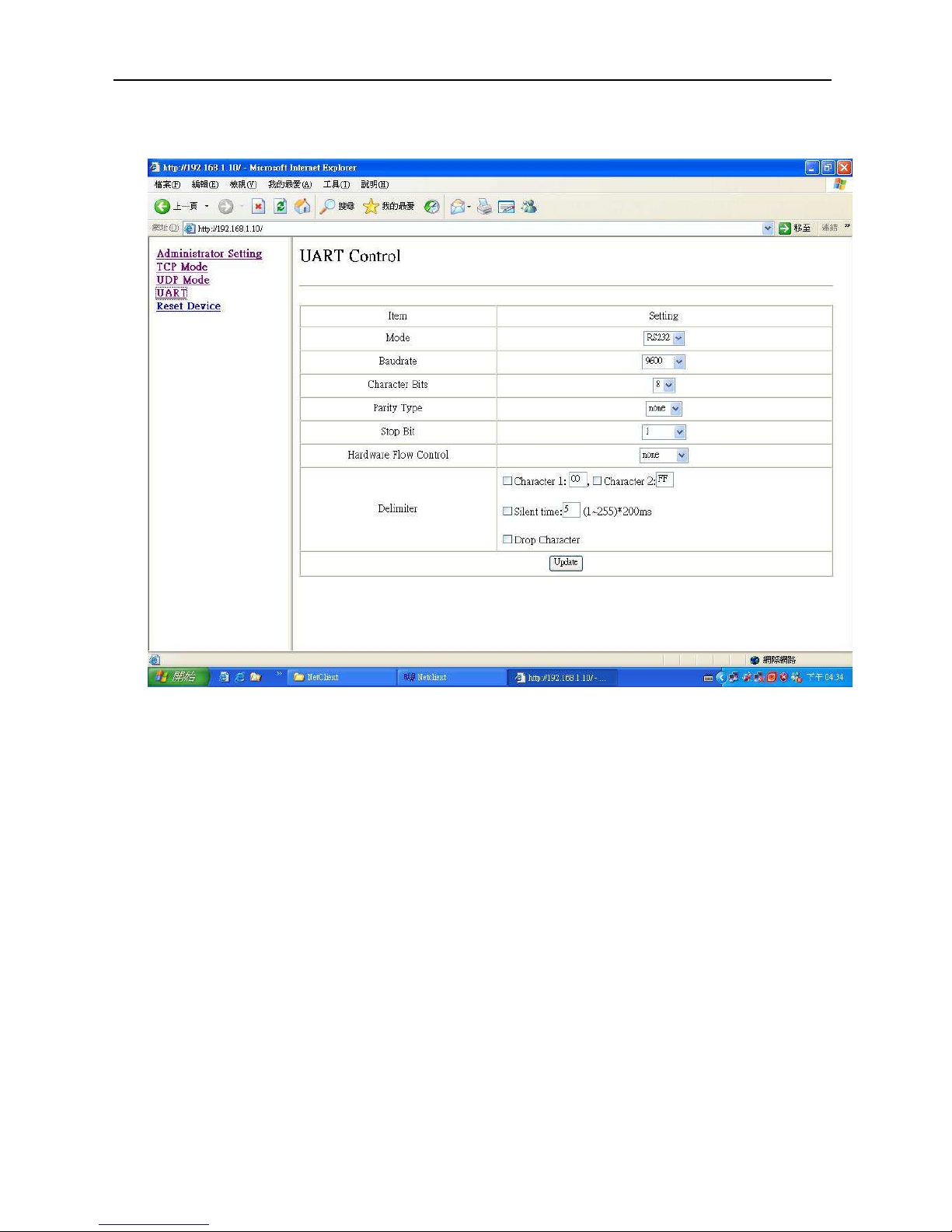
14. UART: You must set UART Control to RS232,9600,8,N,1 for PoE operation.
Mode: Set to RS232 for PoE operation.
Baud rate: Set to 9600 bps for PoE operation.
Character Bits: Set to 8 bits for PoE operation.
Parity Type: Set to none parity for PoE operation.
Stop Bit: Set to 1 stop bit for PoE operation.
Hardware Flow Control: Set to none flow control for PoE operation.
When you have finished the set up, click on Update to update your setting.
Page 13
User’s Manual
PSE-608R(I)/616R(I)/624R
13
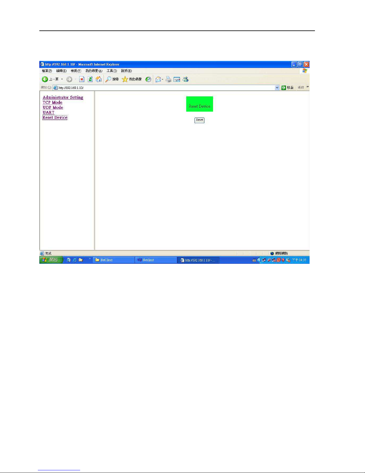
15. When you have configured your set up, you must reset the device to take effect.
Page 14
User’s Manual
PSE-608R(I)/616R(I)/624R
14
3. Software Utility Installation
Before you start to remote configuring PD, please install the software utility. Through the
software utility, you can easily to control the PD that connect with PoE and view the PD
parameter information. The software utility provides GUI interface and user can easily to
start with it. The software utility supports Windows environment – Window 98, 2000,
XP,Vista and Window 7. Please follow the below steps to install the software utility.
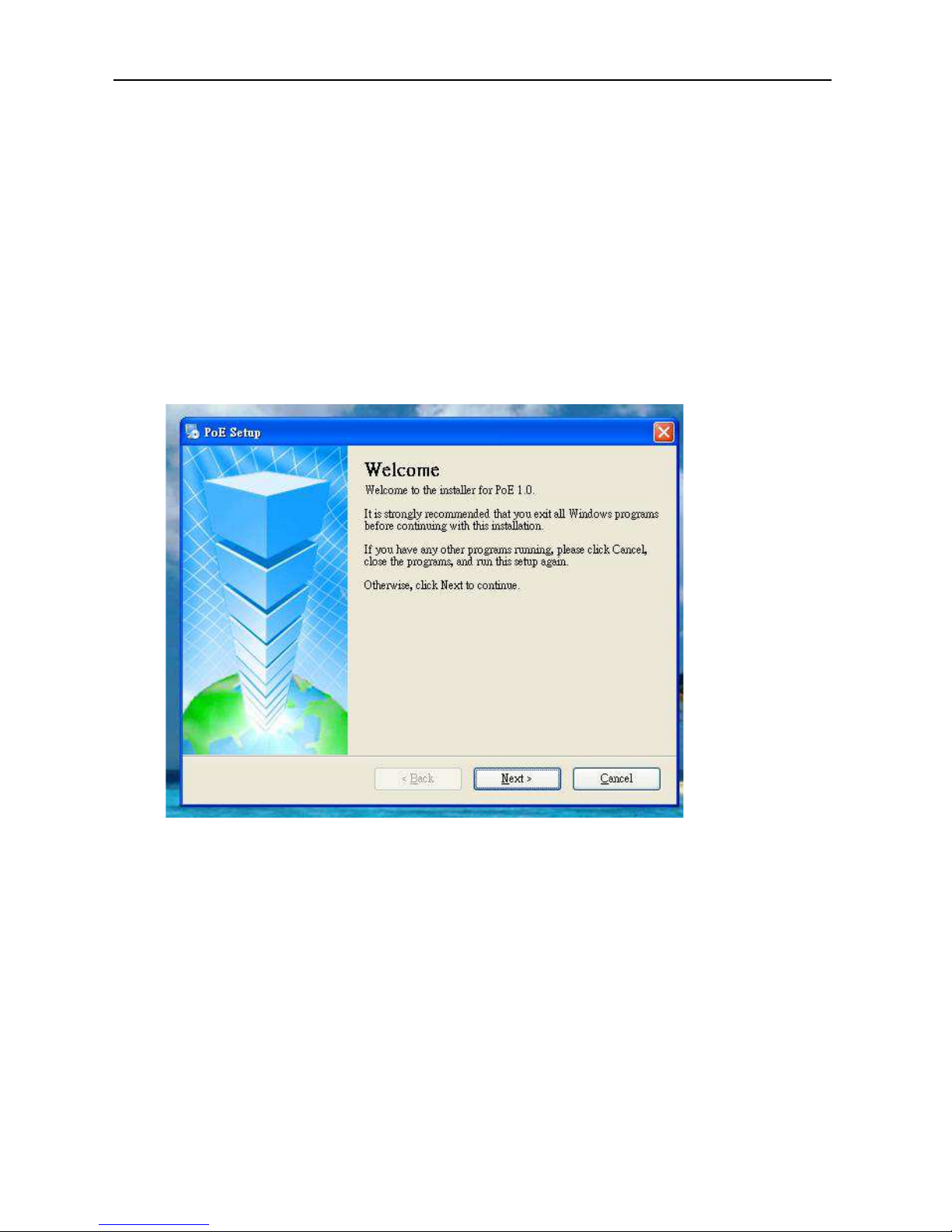
1. Insert the software utility CD-ROM into your CD-ROM drive.
2. Run the “setup.exe”.
3. You will see the installation screen display.
4. Then, click the “OK” button to go next step.
Page 15
User’s Manual
PSE-608R(I)/616R(I)/624R
15
4. GUI Management
Display and Illustration
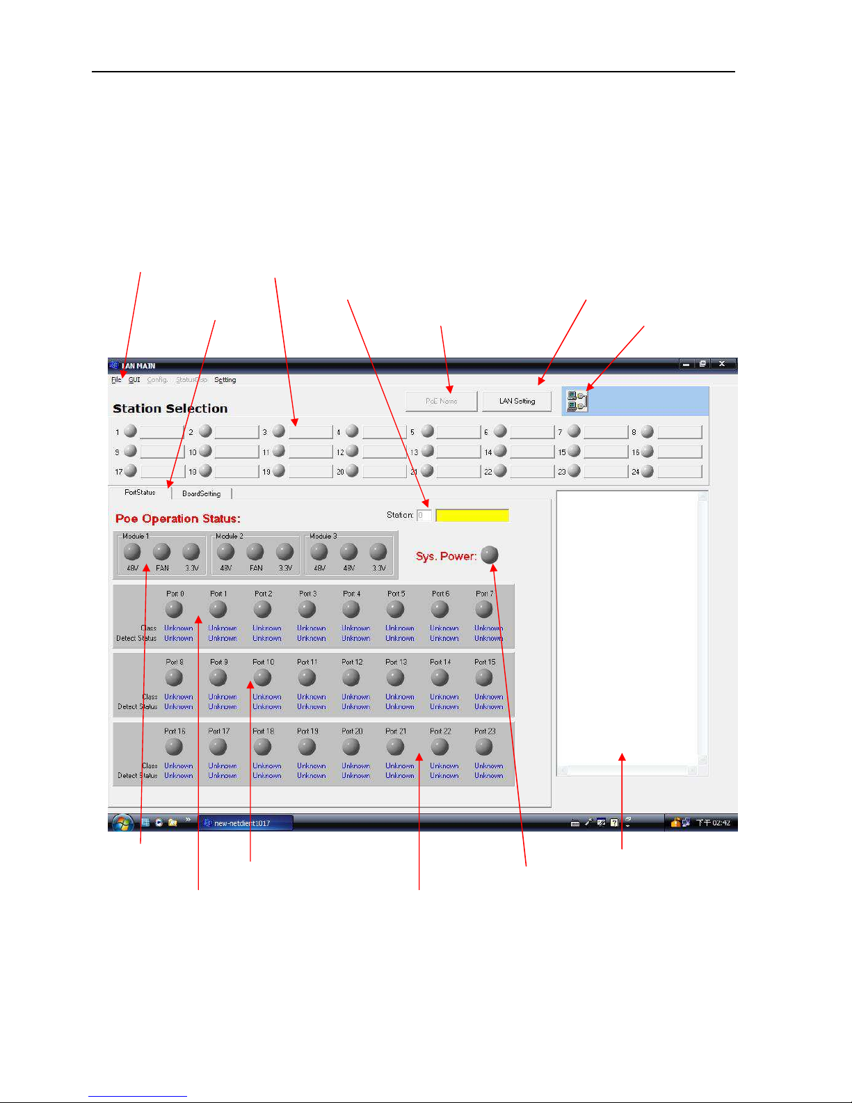
Connect the PSE with a PC through the remote control port. Then, run the software
utility (Netclient). You will see the main utility interface below.
Tools bar PSE station selection & alarm indicator
Display PSE station PSE station name&IP setting
Display page select PSE port name setting legend tool
PSE power & fan alarm indicator message window
PSE port 9~16 status PSE alarm summary
PSE port 1~8 status PSE port 17~24 status
Page 16
User’s Manual
PSE-608R(I)/616R(I)/624R
16
System Login
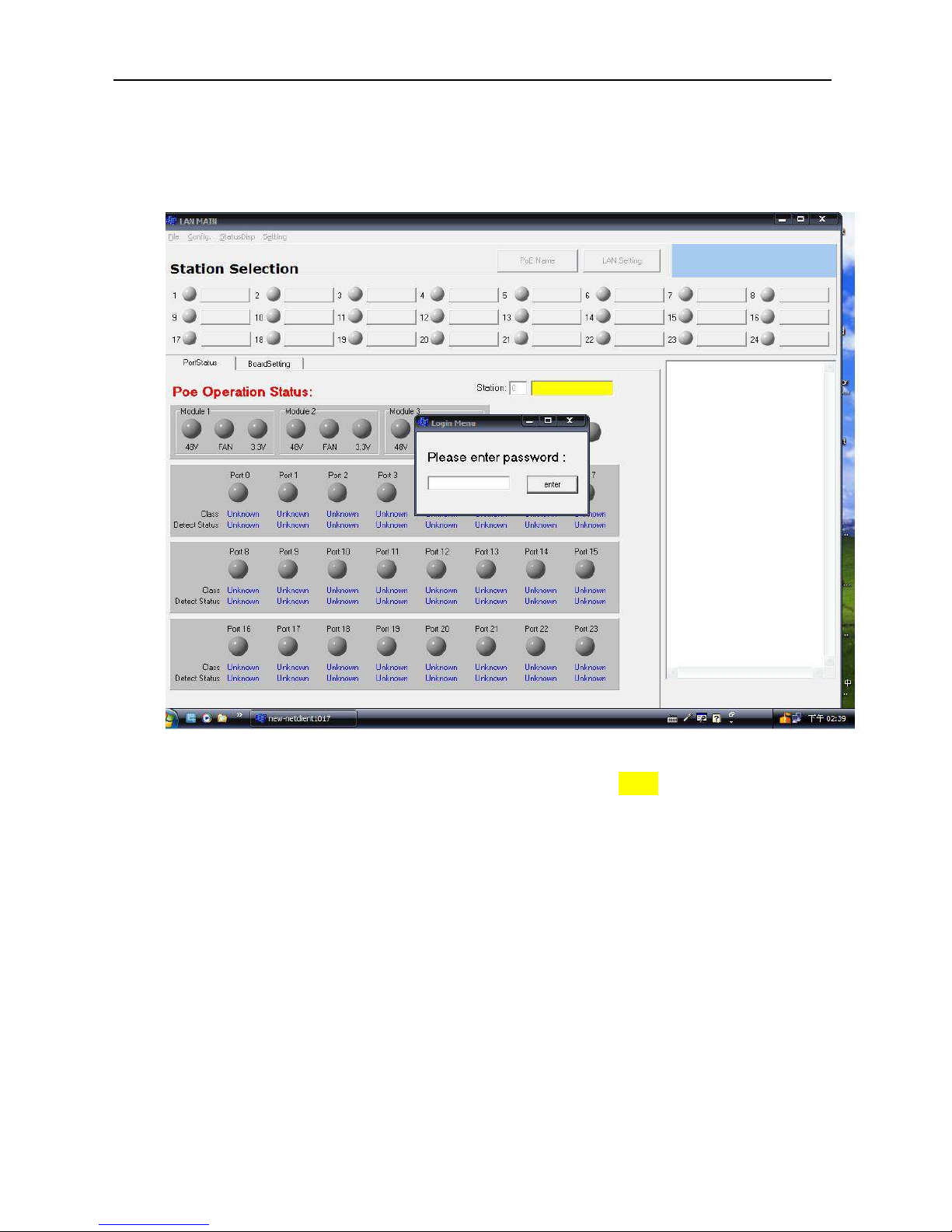
Now Run the management software, the system will show the diagram below.
enter the password, first enter the default setting which is “0000”
Page 17
User’s Manual
PSE-608R(I)/616R(I)/624R
17
Modify Password
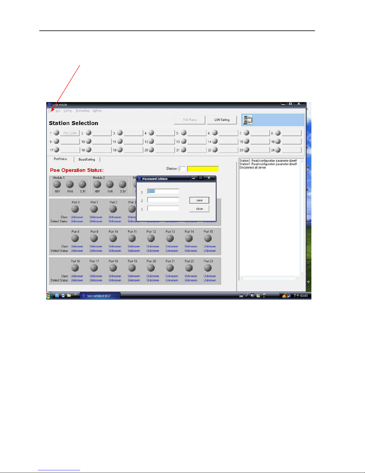
Click “File” and select “Modify PSW”, you can modify the password, the system permits 3
sets of password.
Page 18
User’s Manual
PSE-608R(I)/616R(I)/624R
18
Edit Station TCP/IP
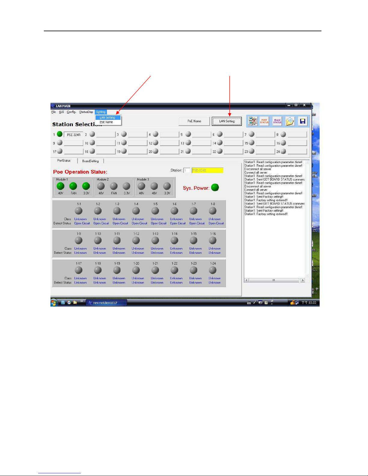
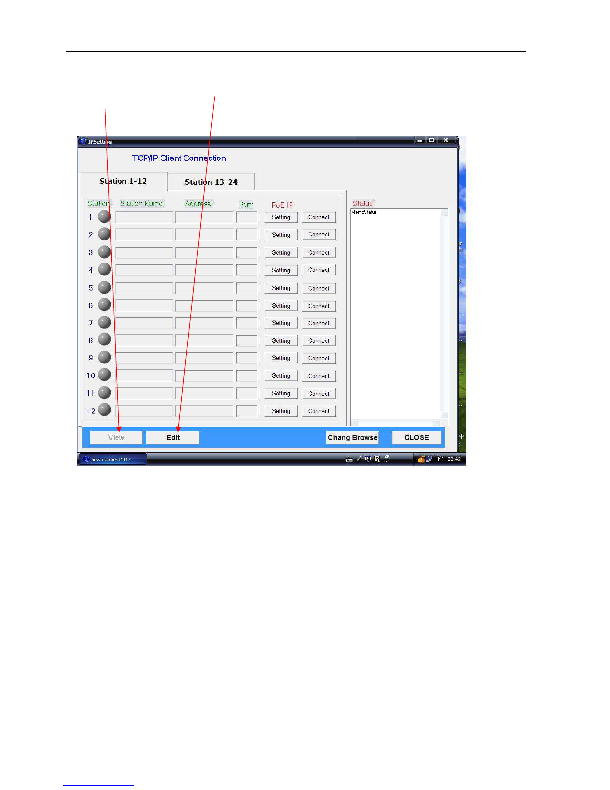
Click “Setting”, and select “LAN Setting”, or click “LAN Setting” icon, the screen will enter
IP Setting window.
Page 19
User’s Manual
PSE-608R(I)/616R(I)/624R
19
In the IP Setting display window, you can edit the station name, TCP/IP address and port
number. Click the Edit icon to modify this parameter. In the Edit window, click the View icon
to display TCP/IP parameter.
Station Name: You can assign a name to the PSE device.
Address: You can assign the IP address for this PSE station.
Port:: You can assign the port number for this PSE station.
Page 20
User’s Manual
PSE-608R(I)/616R(I)/624R
20
Edit Remote PoE IP
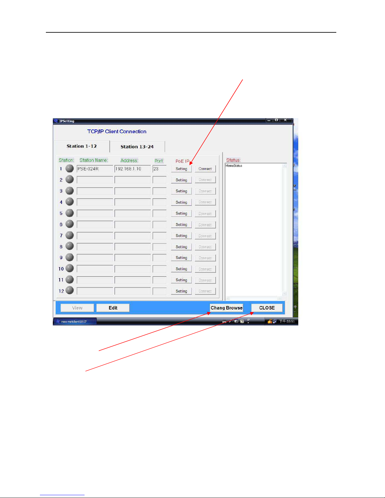
In the IP Setting display window, you can use “PoE IP Setting” icon to start the
web-browser. To modify the remote PoE TCP/IP parameter, please reference RJ-45
Remote Control Port of section 2 Hardware Description (page 7).
Change Browse icon: You can use this icon to change the web-browser for remote PoE IP
edit. The default web-browser is Microsoft Internet Explorer.
CLOSE icon: close IP Setting window, return to main page window.
Page 21
User’s Manual
PSE-608R(I)/616R(I)/624R
21
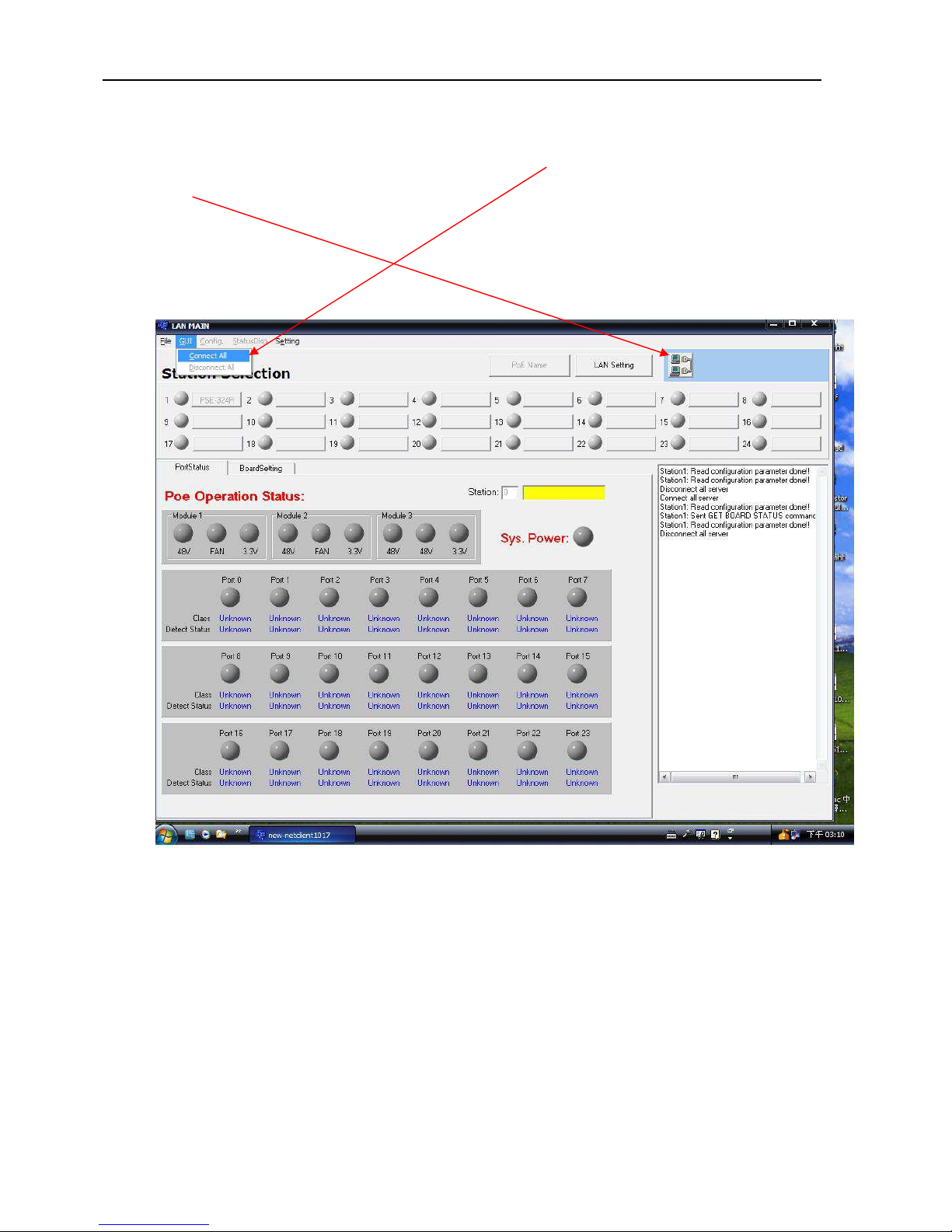
GUI Connect All
In the main page window, click “GUI” and select “Connect All” command or click “connect
all” icon, if the Station Selection window shows the name icon and displays power
status(green or red) light, it means that the PSE connection is correct. You can then select
station to configure you PSE.
Page 22
User’s Manual
PSE-608R(I)/616R(I)/624R
22
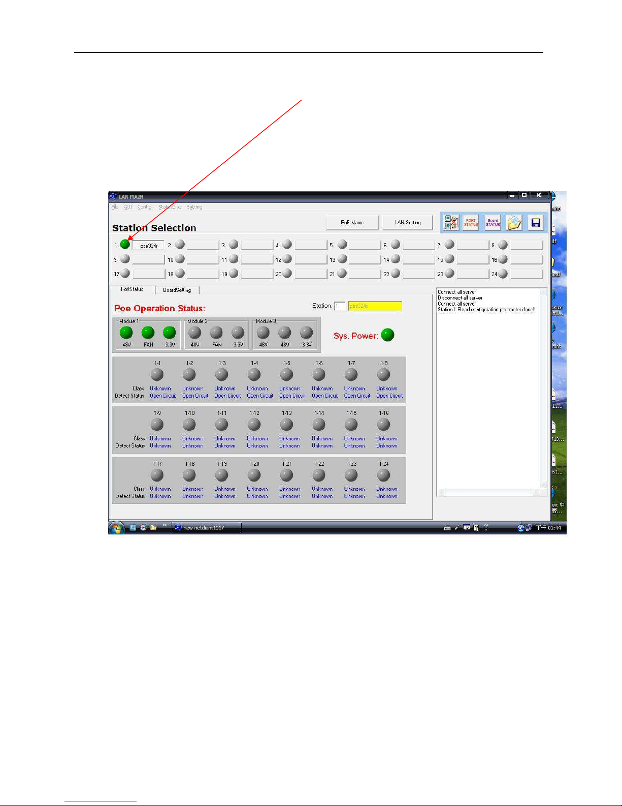
GUI connect example:
In the Station Selection window, the LED indicates real time connection of PSE.
Green-----this connection and PSE power are normal.
Red--------this connection is OK but PSE power is not correct.
Orange---this connection is not working..
Gray-------this station is not setting.
Page 23
User’s Manual
PSE-608R(I)/616R(I)/624R
23
Single Station Connect/Disconnect
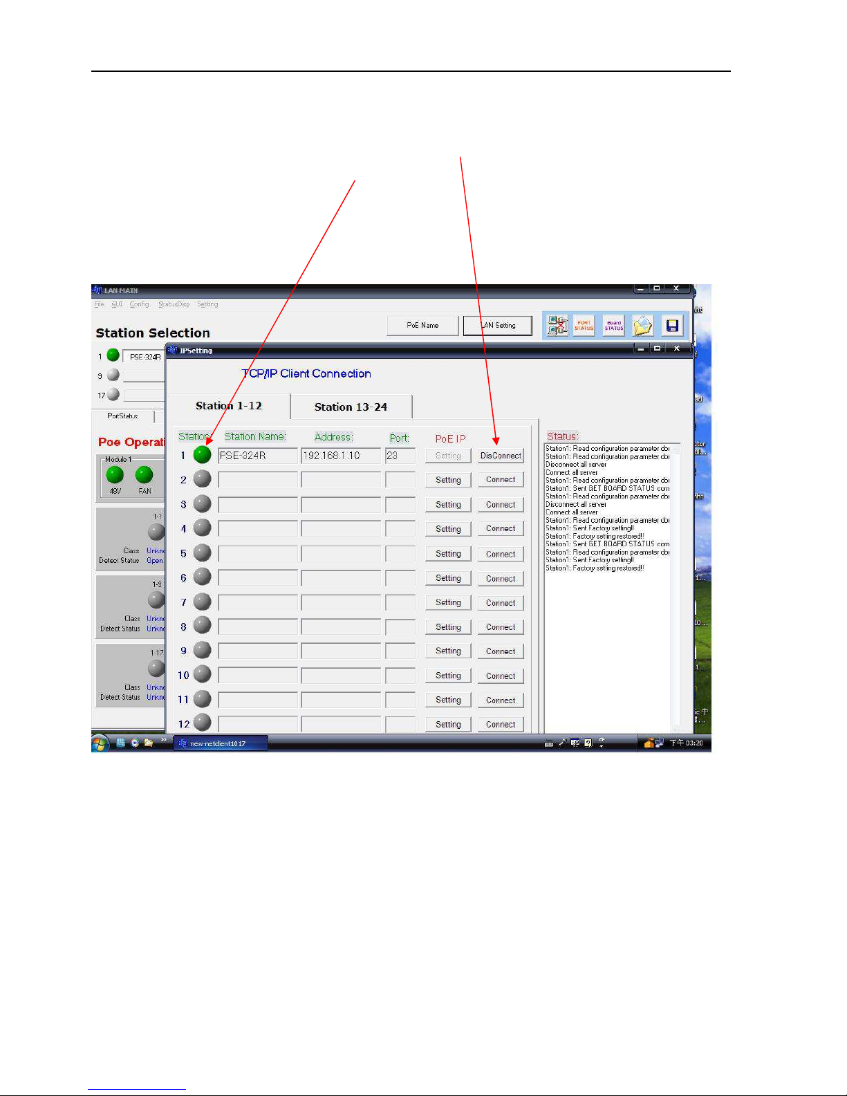
In the IP Setting window, you can click Connect/Disconnect icon to enable/disable single
station connection, the LED indicates real time status of TCP/IP.
Green-----TCP/IP connection is OK.
Red--------TCP/IP connection is not working.
Gray-------TCP/IP parameter is not setting.
Page 24
User’s Manual
PSE-608R(I)/616R(I)/624R
24
Station and Status Window Select
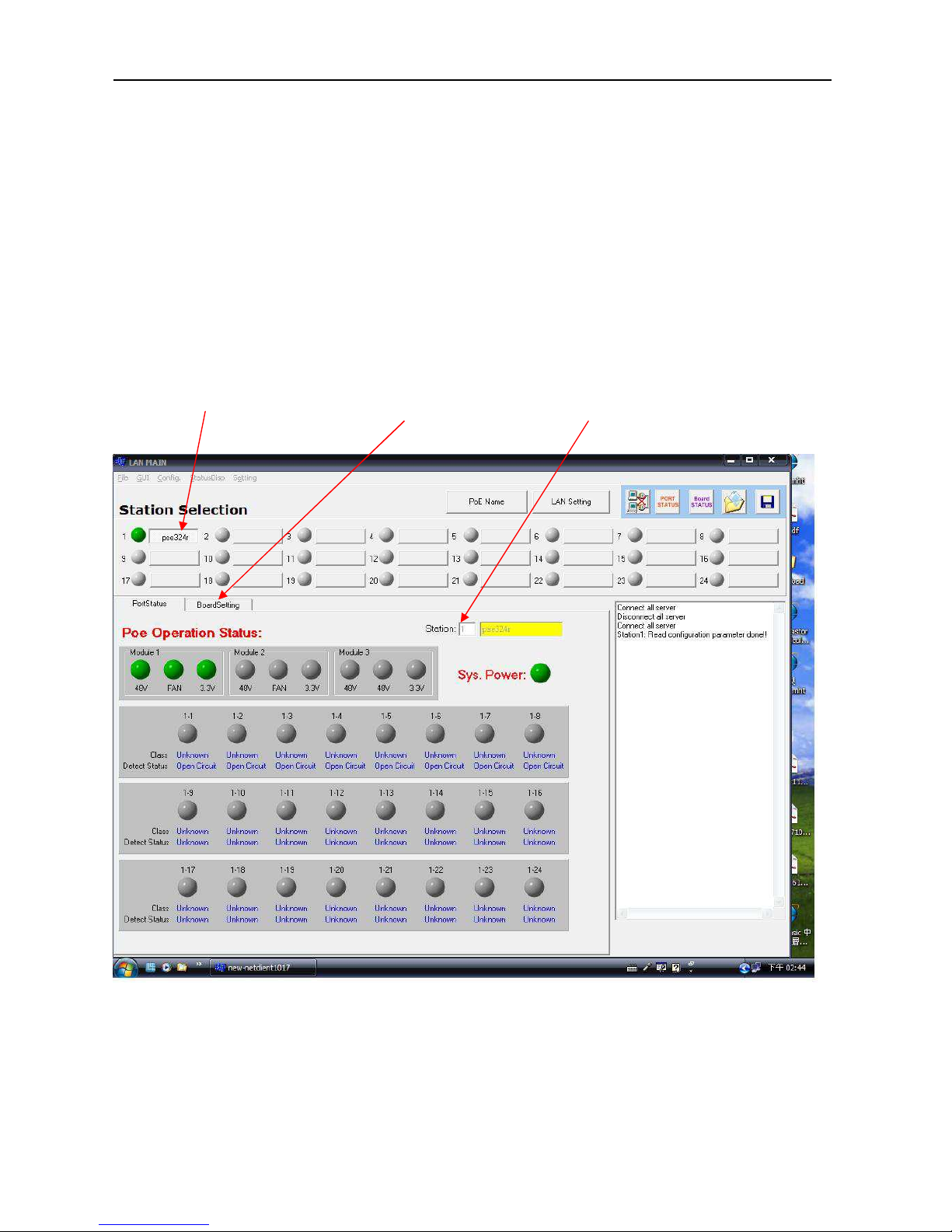
The PSE management software can monitor 24 PSE simultaneously. In the GUI Disconnect
All mode, only the TCP/IP Status display window can be used to set the TCP/IP parameter.
In the GUI Connector All mode, there two display windows can choose - Port Status & Board
Setting.
Port status and Board Setting show relative PSE Station status. If you want to change the
status display window, only use the mouse to choose the relative word icon. If you want to
change the station, also use the mouse to choose the station name icon.
Station Select display icon Status display icon PSE station display
Page 25
User’s Manual
PSE-608R(I)/616R(I)/624R
25
Edit Port Name
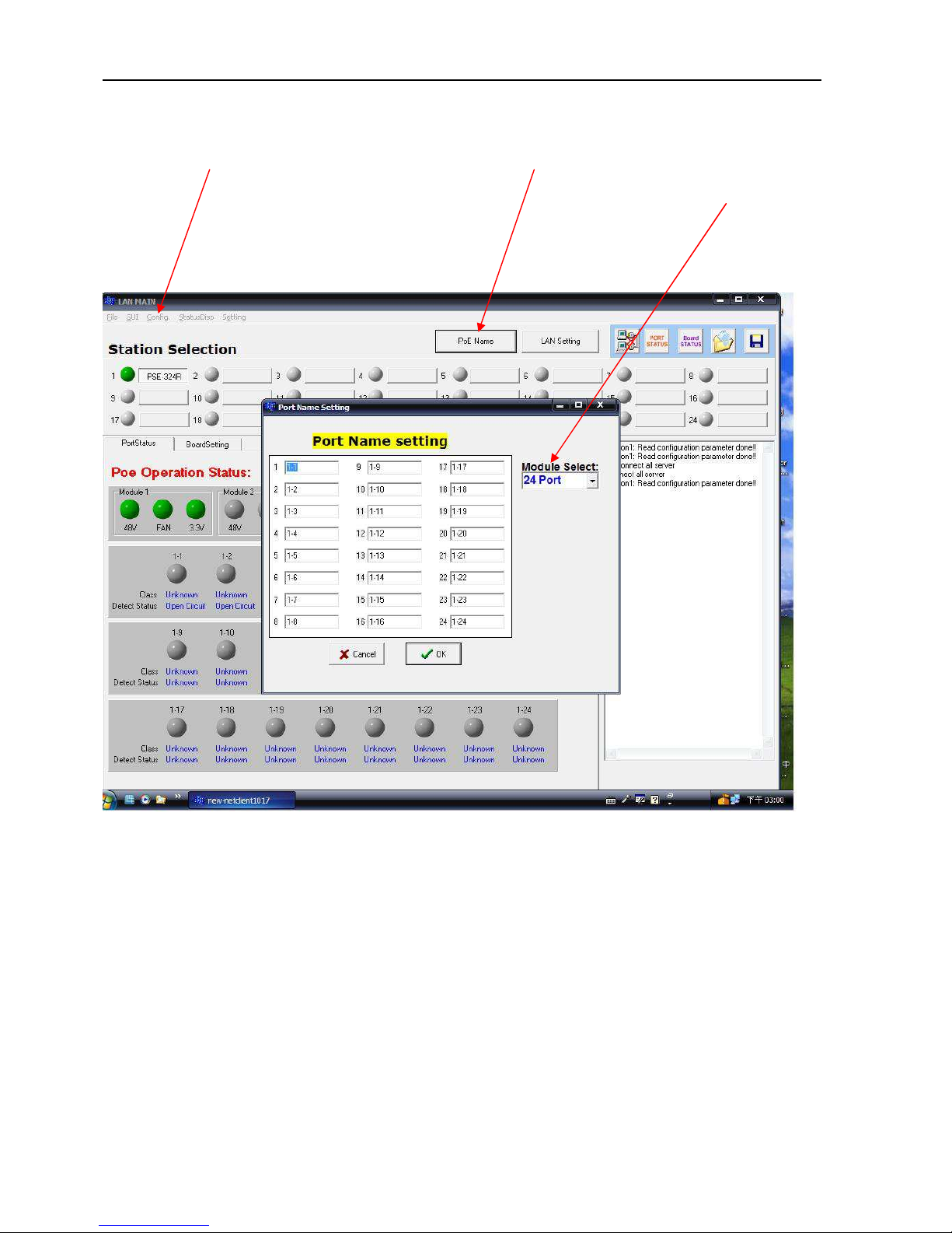
Click “Setting”, and select “PoE Name” or click the “PoE Name” icon. The screen will enter IP
Setting window. You can assign a name to the PSE port individually. In the “Module Select”
window, select the suitable port that you require.
Page 26
User’s Manual
PSE-608R(I)/616R(I)/624R
26
Configuration
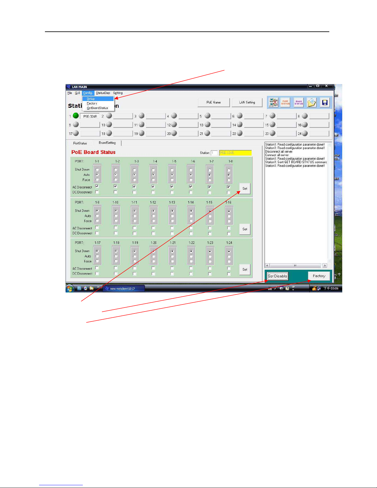
. In the main page window, click “Config”, and select “Setup”, the screen will show the
system control panel as below.
Set icon: Apply the operation mode to PSE system.
Set Enable/Set Disable icon: Change the Board Status window to set enable/disable.
Factory icon: Apply the factory setting to PSE system.
You can setup Operation Mode/ AC Disconnect/ DC Disconnect of each port individually,
then, click “Set”.
PSE port operates in one of three modes: auto mode, force mode and shutdown mode.
In auto mode, the port will detect and classify a PD to connect to, then immediately turn
on the power if the detection was successful. In force mode, the port will not detect and
classify a PD to connect to, but immediately turn on the power to the port. In shutdown
mode, the port is disabled and does not detect or power on a PD.
Page 27
User’s Manual
PSE-608R(I)/616R(I)/624R
27
Factory Setting
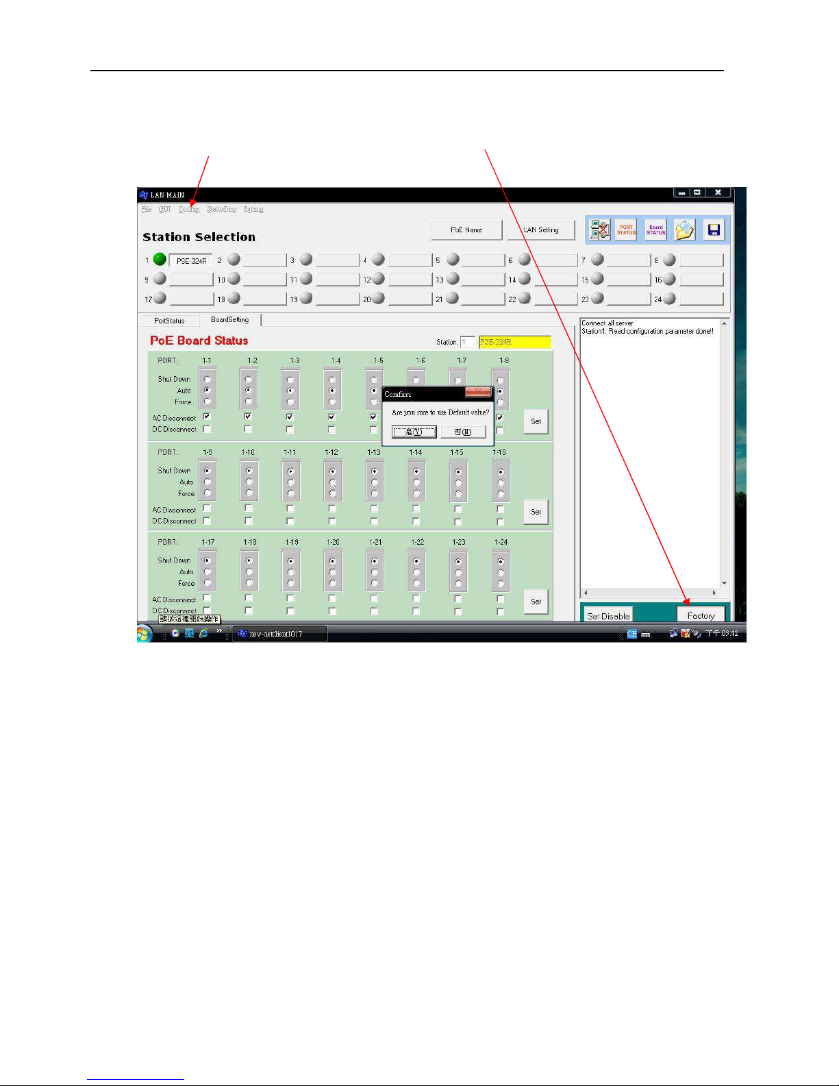
Click “Config”, and select “Factory” or click the “Factory” icon. The screen will show the
factory setting control panel as below:
then click “Y” for the Factory Setting.
Page 28
User’s Manual
PSE-608R(I)/616R(I)/624R
28
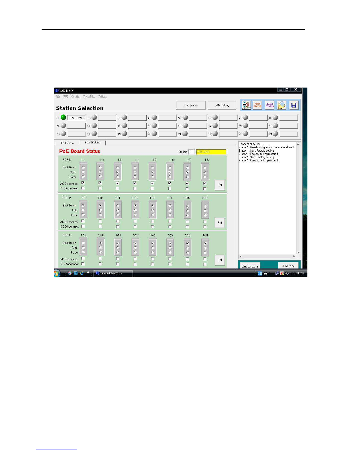
Factory setting as below:
Operation Mode → Auto (Auto, Force & Shutdown)
AC Disconnect → On (On & Off)
DC Disconnect → Off (On & Off)
Page 29
User’s Manual
PSE-608R(I)/616R(I)/624R
29
Board Status
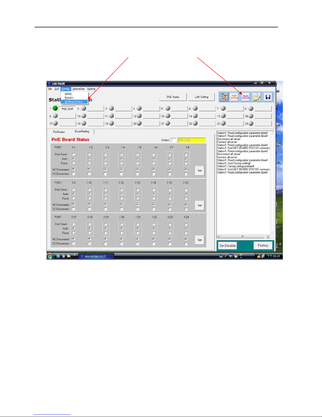
Click “Config”, and select “GetBoardStatus”, or click “Board STATUS” icon, the screen
will show current status of each port.
Page 30
User’s Manual
PSE-608R(I)/616R(I)/624R
30
Port Status
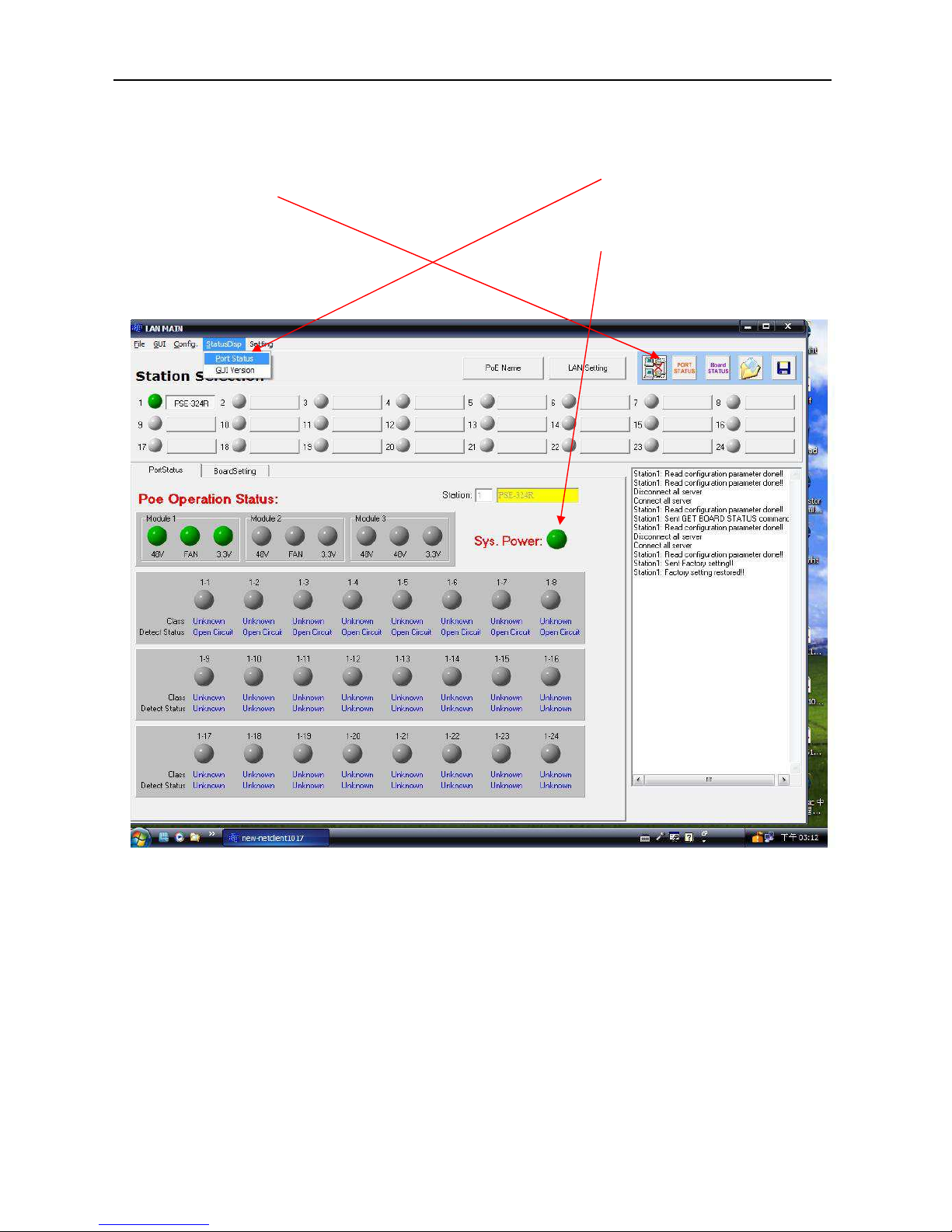
In the main page window, click “StatusDisp”, and select “PortStatus”, or click the “PORT
STATUS” icon, the screen will show current status of each port and current power supply
status of each module.
If all power modules are working normally, the “Sys. Power” will show a green light, if any
module has failed, the light will turn to red.
Page 31
User’s Manual
PSE-608R(I)/616R(I)/624R
31
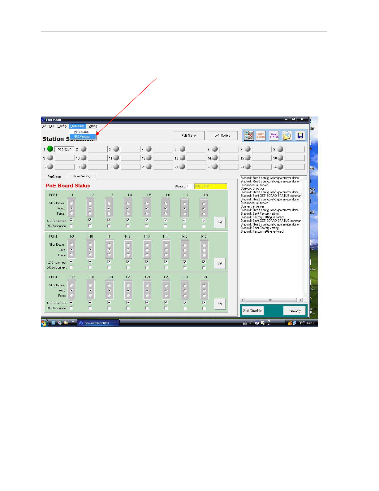
GUI Version
Click “StatusDisp”, and select “GUI Version”, the screen will show the version of the EMS
utility
Page 32
User’s Manual
PSE-608R(I)/616R(I)/624R
32
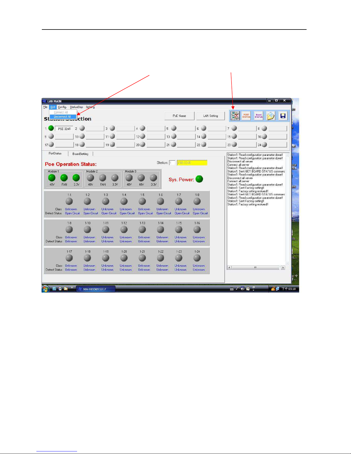
GUI Disconnect All
Click the “GUI”, and select “Disconnect All”, or click the “GUI disconnect all” icon to
disconnect the communication between GUI and PSE.
Page 33
User’s Manual
PSE-608R(I)/616R(I)/624R
33
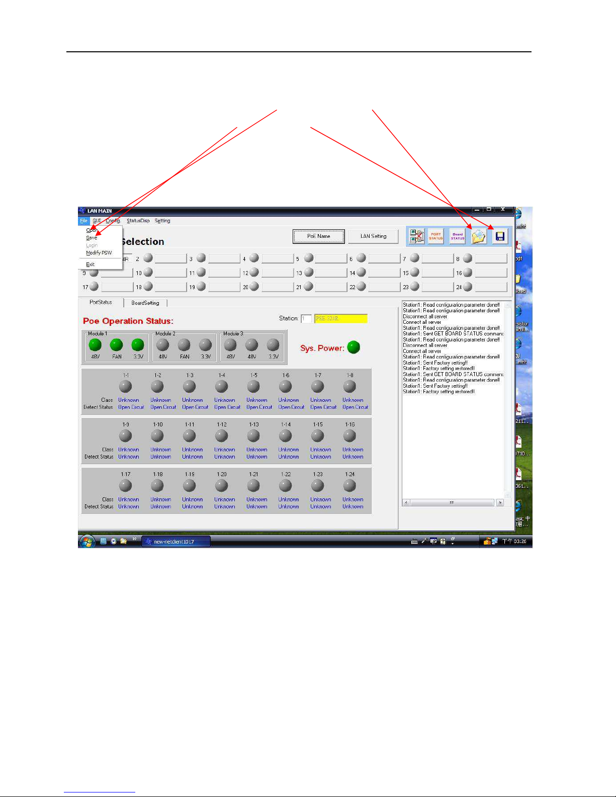
File Open and Save
You may click “File” and select “Open”, or click the ”Open file” icon, to open the previous
setting file. Click “Save”, or “Save file” icon, to save the current setting.
Page 34
User’s Manual
PSE-608R(I)/616R(I)/624R
34
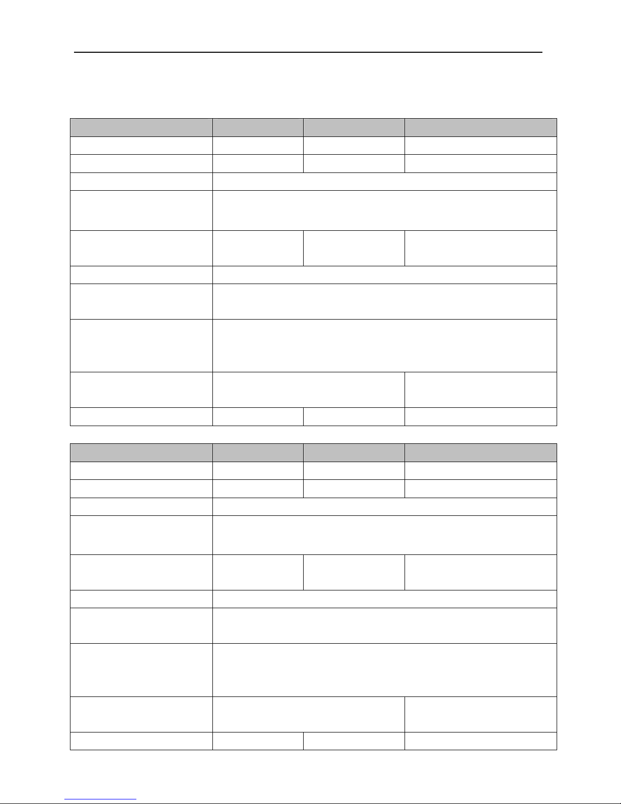
5. Technical Specification
PARAMETER PSE-608R PSE-616R PSE-624R
Data Ports 8 16 24
PoE Ports 8 16 24
Console Port 1× RJ45 console interface for management
Output power
(per port)
DC 54V@600mA (AC input)
Vo=Vi-1V (DC input)
Power consumption
(maximum)
264W 528W 792W
AC Input 100~240VAC,50-60Hz
DC Input
(Non-isolated)
DC -42V ~ -57V
Environment
Operating Temperature: 0℃~40℃
Storage Temperature: -20℃~80℃
Humidity: 10%~95%RH (non condense)
Dimensions
430(W) x 290(D) x 44(H)
19” Rack-Mount / 1U
430(W) x 400(D) x 44(H),
19” Rack-Mount / 1U
Weight 3.6kg 4.9kg 6.5kg
PARAMETER PSE-608RI PSE-608RI+ PSE-616RI
Data Ports 8 8 16
PoE Ports 8 8 16
Console Port 1× RJ45 console interface for management
Output power
(per port)
DC 54V@600mA (AC input)
DC 51V@600mA (DC input)
Power consumption
(maximum)
264W@AC
150W@DC
264W@AC
264W@DC
528W@AC
300W@DC
AC Input 100~240VAC,50-60Hz
DC Input
(isolated)
DC 40V~60V
Environment
Operating Temperature: 0℃~40℃
Storage Temperature: -20℃~80℃
Humidity: 10%~95%RH (non condense)
Dimensions
430(W) x 290(D) x 44(H)
19” Rack-Mount / 1U
430(W) x 400(D) x 44(H),
19” Rack-Mount / 1U
Weight 4.6kg 5.6kg 7.2kg
Page 35
User’s Manual
PSE-608R(I)/616R(I)/624R
35
 Loading...