

Page 1

HARRIER
and
HARRIER R
User Manual
Please read this before use
MSB10352/2-56
MSB10352R/2-5
Page 2

2
SIGNS
WARNING!
Warning of potential injury or health risk.
DANGER!
Risk of electric shock with potential for severe injury or death as a consequence.
DANGER!
Biohazard with potential for risk to health or death as a consequence.
DANGER!
Risk of explosion with potential for severe injury or death as a consequence.
This manual was prepared with special care.
MSE CENTRIFUGES LTD may change the manual at any time
and
without notice because of improvements, typographical errors, inaccuracies of current information
or improvements to facilities.
You can find the current version of the user manual on our website under: www.mseuk.com
DOWNLOADS section.
Page 3
3
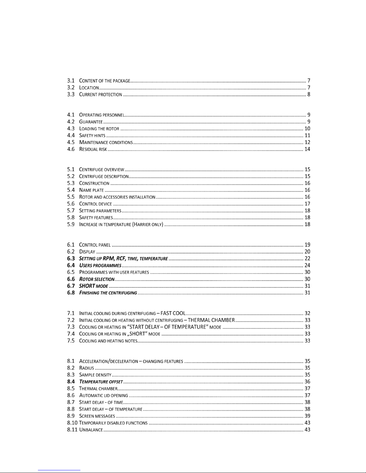
Content
1 APPLICATION ......................................................................................................................................... 5
2 TECHNICAL SPECIFICATION .................................................................................................................... 6
3 INSTALLATION ....................................................................................................................................... 7
4 SAFETY NOTES ....................................................................................................................................... 9
5 OPERATING ......................................................................................................................................... 15
6 CENTRIFUGING .................................................................................................................................... 19
7 TEMPERATURE CONTROL .................................................................................................................... 32
8 PARAMETERS OF CENTRIFUGATION .................................................................................................... 34
Page 4
4
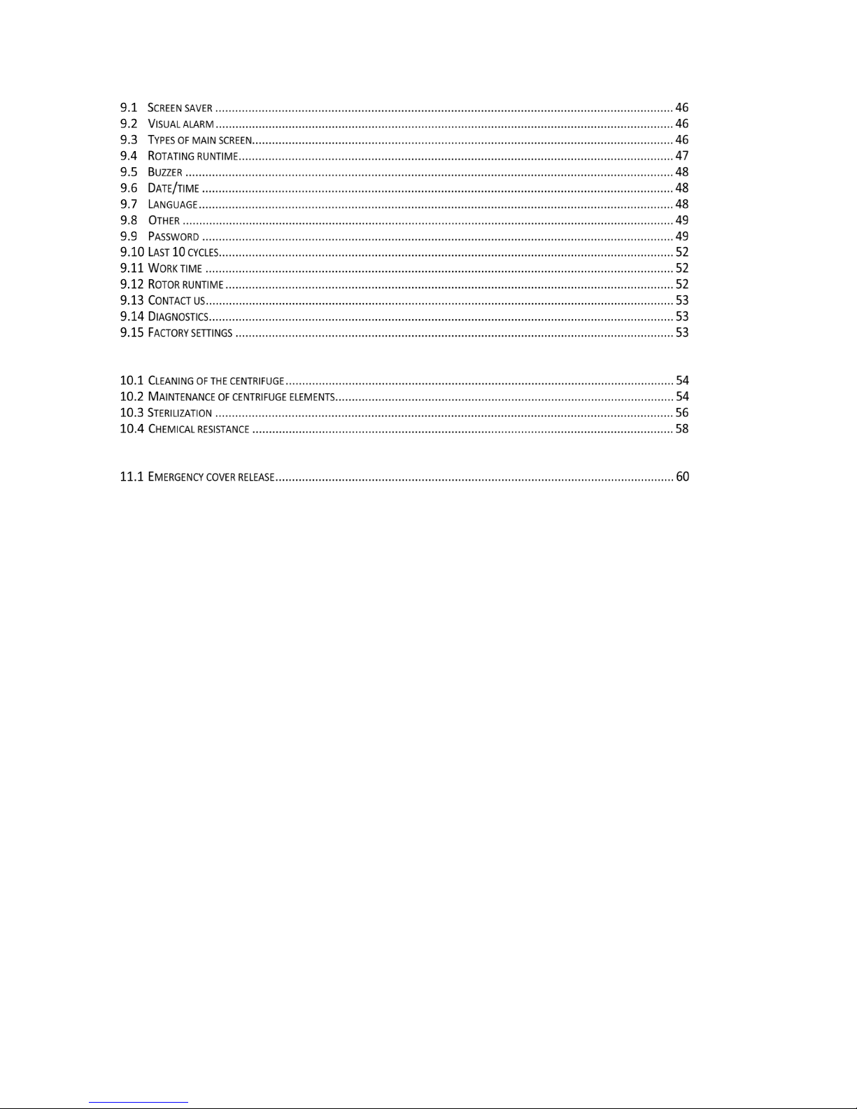
9 MENU .................................................................................................................................................. 45
10 MAINTENANCE .................................................................................................................................... 54
11 TROUBLESHOOTING ............................................................................................................................ 59
12 GUARANTEE ........................................................................................................................................ 61
13 DISPOSAL ............................................................................................................................................ 62
14 MANUFACTURER’S INFO ..................................................................................................................... 63
15 ANNEXES ............................................................................................................................................. 64
OPTIONAL ACCESSORIES
DECLARATION OF DECONTAMINATION - REPAIR
DECLARATION OF DECONTAMINATION - RETURN
STATEMENT OF CONFORMITY
• DECLARATION OF CONFORMITY (ROHS 2 2011/65/EU)
• CONVERSION TABLE FOR RPM/RCF (NOMOGRAM)
Page 5

5
1 Application
The Harrier/R/RH centrifuges are benchtop laboratory centrifuge for in vitro diagnostic (IVD).
Devices are used for separation samples taken from people's, animals’ and plants’ components of
different densities, under the influence of the centrifugal force, to provide information about their
biological state (Harrier – ventilated, Harrier R – with cooling, Harrier RH – with cooling and heating).
Its construction ensures easy operation, safe work and wide range of applications
at laboratories engaged in routine medical analyses, biochemical research works etc.
In the centrifuge, it is prohibited to centrifuge caustic, inflammable and explosive
preparations.
Page 6
6
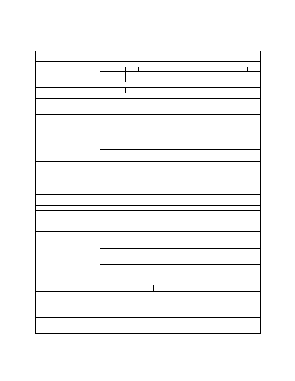
2 Technical specification
manufacturer
MSE Centrifuges Ltd, Mytogen House, 11 Browning Road, Heathfield TN21 8DB
Type
Harrier
Harrier R/RH
mains voltage (L1+N+PE)
230V
100V
110V
120V
127V
230V
100V
110V
120V
127V
±10
±5
±10
±5
mains frequency,
50/60Hz
50Hz/60Hz
50Hz
60Hz
60Hz
power consumption (max.)
600W
980W
current protection [A]
T 6,3A
T 10A
T 10A
T 16A
cooling medium
-
R507 (CFC/HCFC free)
Harrier
Harrier R
Harrier RH
capacity (max.)
1000 ml
speed – RPM
90 ÷ 18000 rpm (step 1 rpm)
relative centrifugal force – RCF
30065 x g (step 1 x g)
Torque, or else the unit need to be
changed (max.)
19148 Nm
running time
00:00:01 ÷ 99:59:59 – [hours, min., sec] (step 1s)
time counting
as start button is pressed / as preselected speed is reached
short-time operation mode – SHORT
yes
continuous operation mode – HOLD
yes
user programmes
100
adjustable temperature
-
-20 ÷ 40°C*
(step 1°C)
-20 ÷ 55°C*
(step 1°C)
initial cooling/heating
PROG 99 (90 ÷ 2500 RPM)
no/ no yes / no yes / yes
guaranteed temperature with max.
rotor speed
-
≤4°C
cooling/heating without centrifuging
no
yes/ no
yes / yes
cooling/heating with centrifuging
no
yes /no
yes / yes
acceleration (ACEL)
10 linear curves
deceleration (DECEL)
10 linear curves
programmable non-linear curves:
Acceleration
10
Deceleration
10
USB communication
yes
Electromagnetic compatibility
according to PN-EN 61326-1:2006
ambient conditions
PN-EN 61010-1 (p.1.4.1)
set-up site indoors only
ambient temperature
2° ÷ 40°C
humidity (maximum relative
humidity)
< 80%
installation category II EN 61010-1
pollution degree 2 EN 61010-1
safety area 300 mm
degree of protection IP21 IP20 IP20
height (H)
380 mm 380 mm
width (W)
443 mm 443 mm
depth (D)
545 mm 695 mm
height with open cover (Hoc)
768 mm 768 mm
noise level
56 dB
weight 230V
41,8 kg
64,8 kg
65,7 kg
weight 120V
45 kg
70,9 kg
71,8 kg
*time and possibility of obtaining a set temperat ure is depende nt on multiple factors, including: roto r type, esta blished RPM, a mbient temperature; accuracy: - ±1*C
appropriate for place of temperature sensor
Menu languages: ENGLISH, FRENC H, GERMAN, SPANISH, ITALI AN, PORTUGUES E, RUSSIAN, SWEDISH, CZECH, POLISH
Page 7
7
3 Installation
Open the package. Remove the box containing the accessories. Take out centrifuge from the container.
Keep the box and packing materials in case of service shipping.
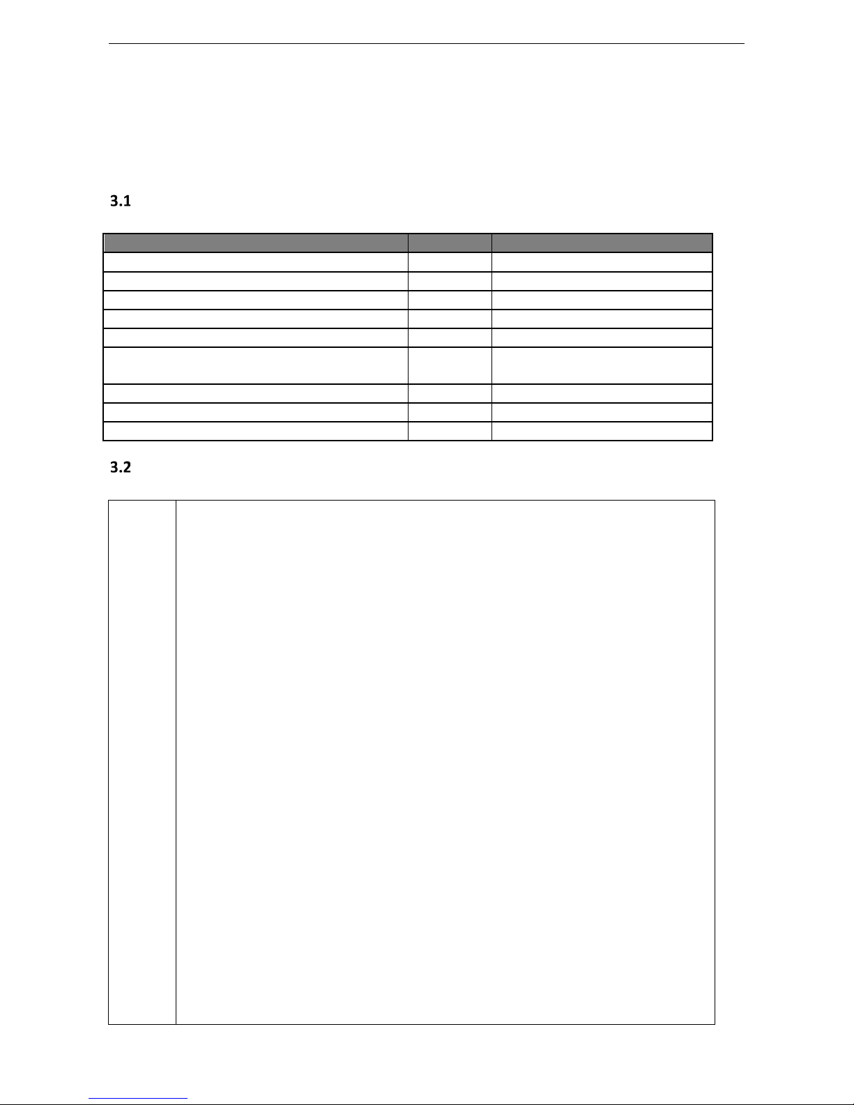
Content of the package
Name
pcs.
cat no.
centrifuge HARRIER/R/RH
1
see name plate
complete clamp 1 17664
spanner for the rotor
1
17665
spanner for emergency opening of the cover
1
17162
power cord 230V / 120V
1
17866/17867
fuse WTA T 6,3A 250V / WTA T10A 250V
/WTA T16A 250V
2 17862/17863/17864
Vaseline 20ml 1 17201
USB A-A cable 1 16655
user manual 1 20352/R/RH/EN
Location
Ensure safe location.
The centrifuge shall not be located near source of heat and shall not be
subjected to direct sunlight.
Centrifuge should be located on a stable and flat-levelled table top.
Centrifuge should be set horizontally on a rigid base.
It is necessary to ensure a ventilation zone of a minimum of 30cm round the
centrifuge from every direction. Do not obstruct ventilation holes !
Benching/Table for centrifuge should have a safety zone of a minimum of
30cm round the centrifuge from every direction (this is needed in case of
malfunction according to EN 61010-020).
Benching/Table for centrifuge should be free of restraints.
Parameters of the centrifuge refer to the above temperatures (see 2.Technical
specification).
When changing from cold to warm, condensation of water will occur inside the
centrifuge. It is therefore important that sufficient time be provided for drying
out of the centrifuge prior to further use of the centrifuge (min. 4 hours).
Do not position the centrifuge so that it is difficult to operate the power
switch.
Supply voltage given on the name plate has to be consistent with local supply
voltage. MSE CENTRIFUGES LTD laboratory centrifuges are 1
st
class safety
devices and they are provided with the three-core cable with the plug resistant
to dynamic loadings. Mains socket shall be provided with the safety pin
(protective earth (PE)).
It is recommended to install emergency cut-out that shall be located far from
Page 8

8
the centrifuge, near the exit or beyond the room.
Before switching on, check whether the centrifuge is connected to power
supply correctly. It is compulsory to use the power cord recommended by the
manufacturer (17866 for 230V, 17867 for 120V)
Before use, check whether the device is correctly intalled.
Current protection
The centrifuge is equipped with thermal current protection. Fuse is situated in the
plug-in socket unit at the back of the centrifuge.
Page 9

9
4 Safety notes
Operating personnel
The laboratory centrifuge can be operated by authorised laboratory personnel after
familiarisation with the user manual.
User manual shall be always held near the centrifuge.
The centrifuge should not be misused.
If the centrifuge is used in a manner not specified by the manufacturer, the
protection provided by the device may be impaired.
Guarantee
The warranty period is 24 months (unless otherwise specified in the purchase
documents).
The service life of the centrifuge specified by the manufacturer is
10 years.
After termination of the warranty period, it is necessary to carry out yearly technical
inspections of the centrifuge.
The Manufacturer reserves the right to make technical changes in manufactured
products.
The maximum period of storage of for centrifuges that are not used is 1 year. After
this period, a technical inspection of the centrifuge should be carried out by service
personnel authorised by the manufacturer.
Page 10
10
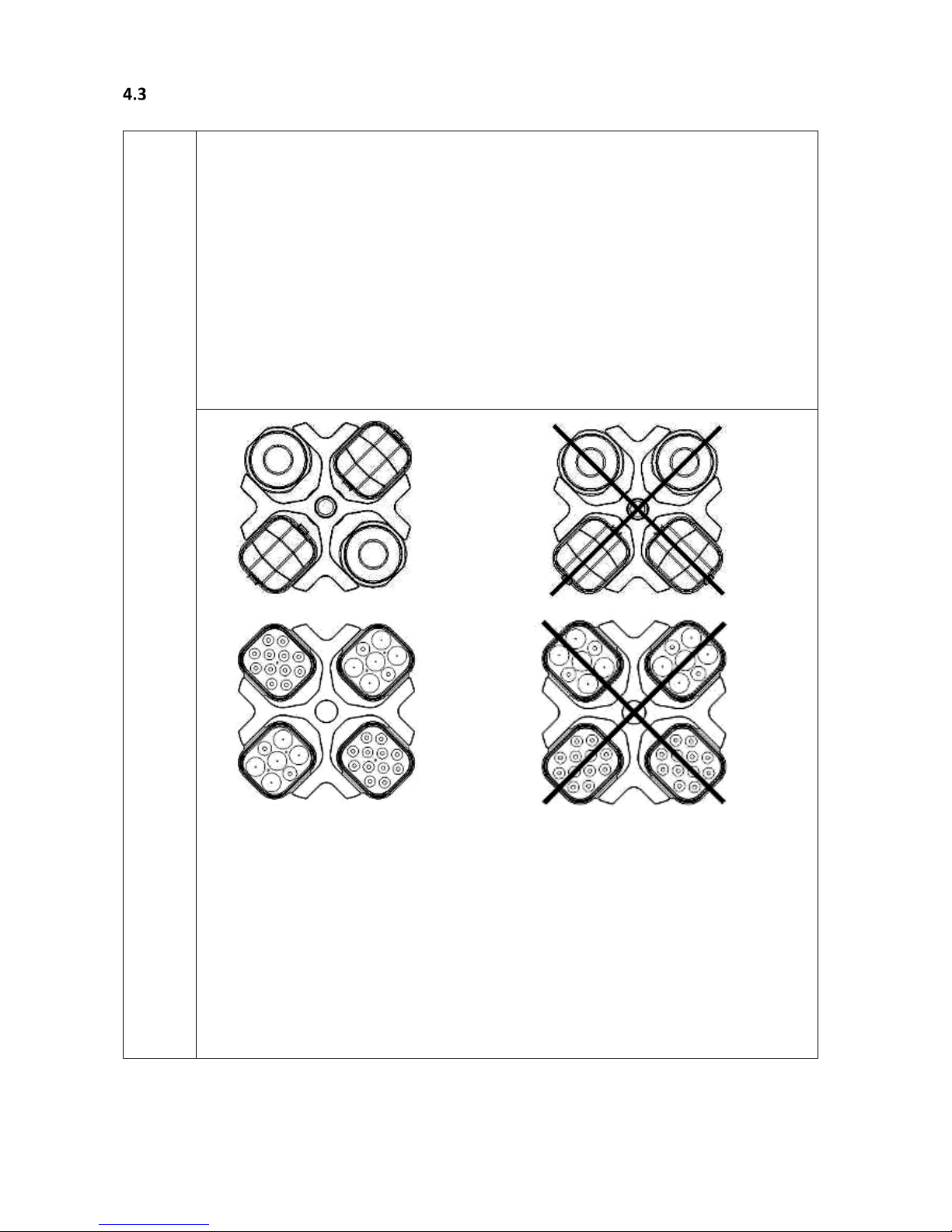
Loading the rotor
Fix the rotor firmly on the motor axis.
Avoid unbalance.
Load opposite buckets with the same accessories.
Centrifugation of the test tubes of different sizes:
There is a possibility to centrifuge test tubes of different sizes; however, it is
absolutely necessary in such cases that opposite buckets and round carriers
be the same.
The mass of different containers with test tubes spun at the same time has
to be comparable. Swing-out rotors must be equipped with all ( two or four
– dependent on the type of rotor) buckets.
Lubricate the swing-out rotor journal pins.
CORRECT
WRONG
CORRECT
WRONG
It is necessary to insert test tubes symmetrically on the opposite sides.
Page 11

11
FILLING TUBES
Fill test tubes outside the centrifuge.
Please pay special attention to the quality and proper thickness of the glass test
tubes walls. Those must be test tubes for centrifuges.
Fill test tubes outside the centrifuge.
Safety hints
ROTORS MAINTENANCE
Lubricate the swing-out rotor trunnion pins.
Use only accessories in good condition.
Protect equipment against corrosion using accurate preventive maintenance.
HS ACCESSORIES MAINTENANCE
Make sure that rubber O-
rings are lightly coated with silicone grease. Use high
vacuum grease, e.g. type „C” by LUBRINA.
HAZARDOUS MATERIALS
MSE Centrifuges accessories are not biotight. For centrifuging infectious materials, it
is necessary to use hermetically closed tubes meeting demands of biotightness,
in order to prevent germs migration into the centrifuge and beyond it.
It is not allowed to subject to
centrifugation toxic or infectious materials with
damaged leak proof seals of the rotor or test-tube. Proper disinfection procedures
have to be carried out after dangerous substances have
contaminated the
centrifuge or its accessories.
EXPLOSIVE AND COMBUSTIBLE MATERIALS
It is not allowed to centrifuge explosive and inflammable materials.
It is not allowed to centrifuge substances prone to reacting as a result of a high
energy supply during centrifugation.
The centrifuge can not be operated in
explosion-endangered areas.
It is not allowed to centrifuge materials capable of generating inflammable or
explosive mixtures when subjected to air.
Page 12

12
Maintenance conditions
START-UP
Prior to switching the centrifuge on, the user must read carefully all sections of this
user manual in order to ensure smooth operation and avoid damages of this device
or its accessories.
In order to protect the centrifuge against unbalance, fill in the test tubes up to the
same weight.
TRANSPORTATION
Centrifuge must not be transported with the rotor mounted on the shaft.
GENERAL HINTS
Only original rotors, tubes and spare parts must be used.
In case of faulty operation of the centrifuge, please contact MSE CENTRIFUGES LTD
Service Department or its authorised representatives.
It is not allowed to switch the centrifuge on if it is not installed properly or rotor
is not fitted correctly.
CENTRIFUGES SUBSTANCES
It is not allowed to exceed load limit set by the manufacturer. Rotors are intended
for fluids of average homogeneous density equal to 1,2 g/cm3
or smaller when
centrifugation is carried out at maximum speed. When fluids of higher density are
used, it is necessary to change the density of the centrifuge’
s sample
in PARAM/DENSITY field.
Page 13

13
INSPECTION PROCEDURES CARRIED OUT BY THE OPERATOR
The operator has to pay special attention to the fact that key centrifuge parts are not
damaged for safety reasons. This is specifically important for:
Centrifuge accessories and especially structural changes, corrosion, preliminary
cracks, abrasion of metal parts.
Screw connections.
Inspection of seals of the buckets if such are used. Special attention must be paid to
all of the rubber (seals) parts. In the case of damage or visible structural changes
defective parts must be replaced for new immediately (Set of seals Cat. No. 18591
available from the manufacturer).
Yearly technical inspection of the centrifuge (after lapse of guarantee).
Only the manufacturer-specified buckets, included in the equipment list, as well as
centrifuge tubes, which diameter, length and durability are suitable, should be used
for spinning in this centrifuge. The use of equipment made by other manufacturers
should be consulted with the manufacturer of the centrifuge.
It is not permitted to lift or shift the centrifuge during operation or rest on it.
It is not permitted to stay in the safety zone (30 cm distance around the centrifuge)
neither leave objects, e.g. glass vessels within this zone.
It is not permitted to put any objects on the centrifuge
COVER OPENING
It is not permitted to open the cover manually in emergency procedure when rotor is
still turning.
Page 14

14
ROTORS
It is not permitted to use the rotors and round carriers with signs of corrosion
or other mechanical defects.
It is not permitted to centrifuge highly corrosive substances which may cause
material impairment and lower mechanical properties of rotor and round
carriers.
It is not permitted to use rotors and accessories not agree
d by the
manufacturer. Only
use commercial glass and plastic test tubes which are
specifically made for centrifuging in this laboratory centrifuge. Do not use poor
quality elements.
Cracking of glass vessels and test tubes could result
in dangerous vibration of the centrifuge.
It is not permitted to carry out centrifugation with the rotor caps taken off or
not screwed tight.
Residual risk
The centrifuge is built according to state-of-the-art standards and recognised safety regulations.
Nevertheless, there still remains some level of residual risk due to improper operation and malfunctions. It
is possible to decrease residual risk by applying strictly the user manual conditions and correcting any
malfunction which could threaten safety immediately.
Page 15

15
5 Operating
Centrifuge overview
The new generation of MSE CENTRIFUGES LTD’s laboratory centrifuges is provided with state-of-theart microprocessor control systems, very durable and quiet asynchronous brushless motors and accessories
consistent with requirements of the present-day user.
Centrifuge description
5
4
3
2
Fig.2. Right side of centrifuge
1 2
1. Power switch
2. USB
3. Control panel
4. Cover
5. Sight glass
6.
Emergency lid
opening
1. Plug-in socket
2. Fuse socket
Fig.1. General view
Fig.3. Assembly of angle rotor
Fig.4. Mains socket
back of the centrifuge
1. Motor shaft
2. Rotor
3. Rotor lid
4. Clamp bolt/rotor
nut
4
3
2
1
6
1
Page 16
16
Construction
The centrifuge has a rigid self-supporting structure. The housing is made of sheet aluminium, the
back is made of steel sheet. Front and cover are made of ABS type plastic. The cover is fixed on steel axles
of hinges and from the front, it is locked with an electromagnetic lock blocking any possibility of opening
during centrifugation. The rotation chamber casing is made of thick steel sheet. The rotation chamber is
made of stainless steel sheet.
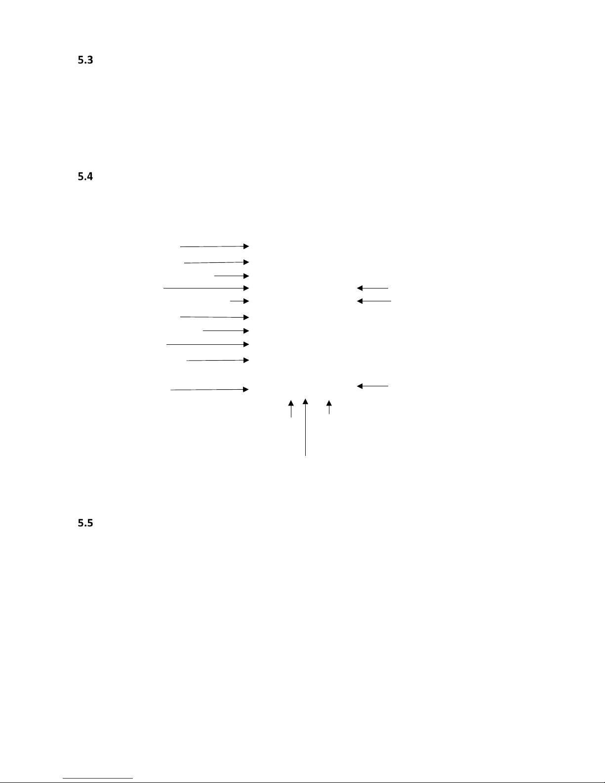
Name plate
Rotor and accessories installation
Connect the centrifuge to the mains (master switch on the back of the centrifuge).
Turn on the centrifuge (button on the side of the centrifuge).
Open the cover of the centrifuge by pressing the COVER key (see section Centrifuging/Control
Panel). Prior to putting the rotor in, please ensure that the rotating chamber is free of impurities,
e.g. such as dust, glass splinters, residues of fluids that must be taken away.
Fit the rotor on the motor shaft screwing it tight on the cone.
Screw-in the clamp for fixing the rotor (clockwise). Ensure it is tight with the supplied spanner for
the rotor.
Swing-out rotors have to be provided with the buckets in all seats. Please remember that every
buckets swings individually and freely. Bucket suspension studs (trunnoin pins) should be lubricated
periodically with petroleum jelly.
Centrifuge model
Catalogue number
Power supply parameters
Rating power
Type and mass of refrigerant
Maximum speed
Date of manufacturing
Serial number
Information about
manufacturer
CE compliance
Fuse type
R
efrigerant does
not contain CFC.
Product should
not be disposed
with other waste.
Dispose according
to national law.
Pay attention when you are seeing this symbol.
Operating of centrifuge may be potentially
harmful.
In Vitro
Diagnostic
device
Read user
manual
Page 17

17
In case of rotors designed with the cover (angled rotor), they must not be used without the rotor
lid. Rotor covers must be closed tightly. Rotor covers ensure smaller drags of the rotors, proper
setting of the test-tubes and airtight sealing.
Please only use buckets intended for the selected types of the rotor.
Fill test tubes outside the centrifuge.
In case of centrifuging in an angle rotor, test tubes (buckets) have to be filled properly in order to
prevent spillage of fluids during centrifuging.
Tubes must be filled so that the material does not
escape.
Please fill tubes according to below formula:
Max liquid level < Tube height −
Internal tube diameter
2
Additionaly please adhere to the manufacturer's restrictions about the filling of the test tube.
It is recommended to equalise vessels loads as much as possible in order to ensure
minimal vibrations during operation.
In order to prolong the lifetime of the rotor and gaskets, rotors will need to be lubricated with the
maintenance oil, while gaskets and threaded parts will need to be lubricated with petroleum jelly.
For replacement of the rotor, please unscrew clamp and then grab the rotor with both hands at
opposite sides, taking it away from drive shaft by pulling it up.
Control device
The microprocessor control unit of the centrifuge allows the selecting, programming and registering
of the work parameters.
centrifugal force
liquid
Internal tube diameter
Page 18

18
Setting parameters
The data setting and read-out system are part of a hermetically closed keyboard with distinctly
accessible operation points. Easily readable displays confirm the selected features and facilitate the
operator’s programming and recording of parameters and condition of the centrifuge.
The centrifuge is provided with the USB interface that enables connection of the centrifuge to an
external PC unit with the printer and recording of the centrifugation parameters.
Safety features
Lid lock
The centrifuge can only be started when the lid is properly closed. Similarly, the lid can only be
opened once the rotor has stopped. In case of emergency opening of the lid during operation, the
centrifuge will be immediately switched-off and the rotor will slow to a complete stop.
Unbalance detecting
Should loads of opposite buckets or carriers in rotors be unbalanced, the drive will be switched-off
during acceleration or operation of the centrifuge and an error message will be displayed.
Rotor verification and checking compatibility with loaded programme
Upon starting centrifuging, the unit verifies the type of the rotor installed and in the case of its
incompatibility with the type indicated in the application or absence of the rotor, the spinning process will
stop with simultaneous displaying of an error message. The conformity of the type of the rotor is signalled
with a single audible signal. If the auto-identification (see 9.8 Other) option is checked, the proper rotor will
be automatically chosen, without the user input.
Rest state inspection
Opening of the centrifuge’s cover by pressing the COVER button is possible, but only when the
rotor is in a state of rest. Use the inspection glass to ensure the rotor is in the rest state. When the rotor is
being stopped, the brake symbol (see 6.2) is visible and goes off when it stops. The opening of the
emergency cover during rotor running is prohibited.
Checking of excessive temperature
If the temperature in rotation chamber exceeds 50°C (Harrier) / 65°C (Harrier R/RH) caused by, for
example, a malfunction of the cooling system, the drive will be switched off and an error message will be
displayed. The reboot is only possible after the device has cooled down.
Increase in temperature (Harrier only)
In uncooled centrifuges, the temperature in the rotor chamber, rotor and sample can increase to
above 40°C, based on the run time, g-force (rcf)/speed and ambient temperature.
Page 19

19
6 Centrifuging
The switching ON/OFF of the power is carried out via the master switch situated on the right side wall
of the centrifuge. All other settings on the centrifuge are done by means of the control panel.
Control panel
The control panel placed on the front casing provides the control of the centrifuge operation.
Control panel
►►
SHORT1
short-time centrifuging
►
START
start centrifugation run
STOP2
end centrifugation run
LID
lid opening
FAST
COOL
start fast cooling mode, precool (Harrier R and Harrier RH only)
BACK/
OPTIONS
exit the current menu / mode type, choose options for simplified display (press and
hold for 1 s.)
▲
UP
navigation in-menu / increasing values
▼
DOWN
navigation in-menu / decreasing values
◄
LEFT
navigation in-menu
►
RIGHT
navigation in-menu
SET
SET
changing parameters / confirming changes
1
the centrifuge is working as long as the key is pressed
2
pressing once – will stop the centrifuging with acceleration features set in the current programme,
pressing twice – will make the centrifuging as fast as possible (quickest feature). During the setting of
parameters, you can use this button for exiting zones on the primary screen without introducing changes.
Page 20
20
Display
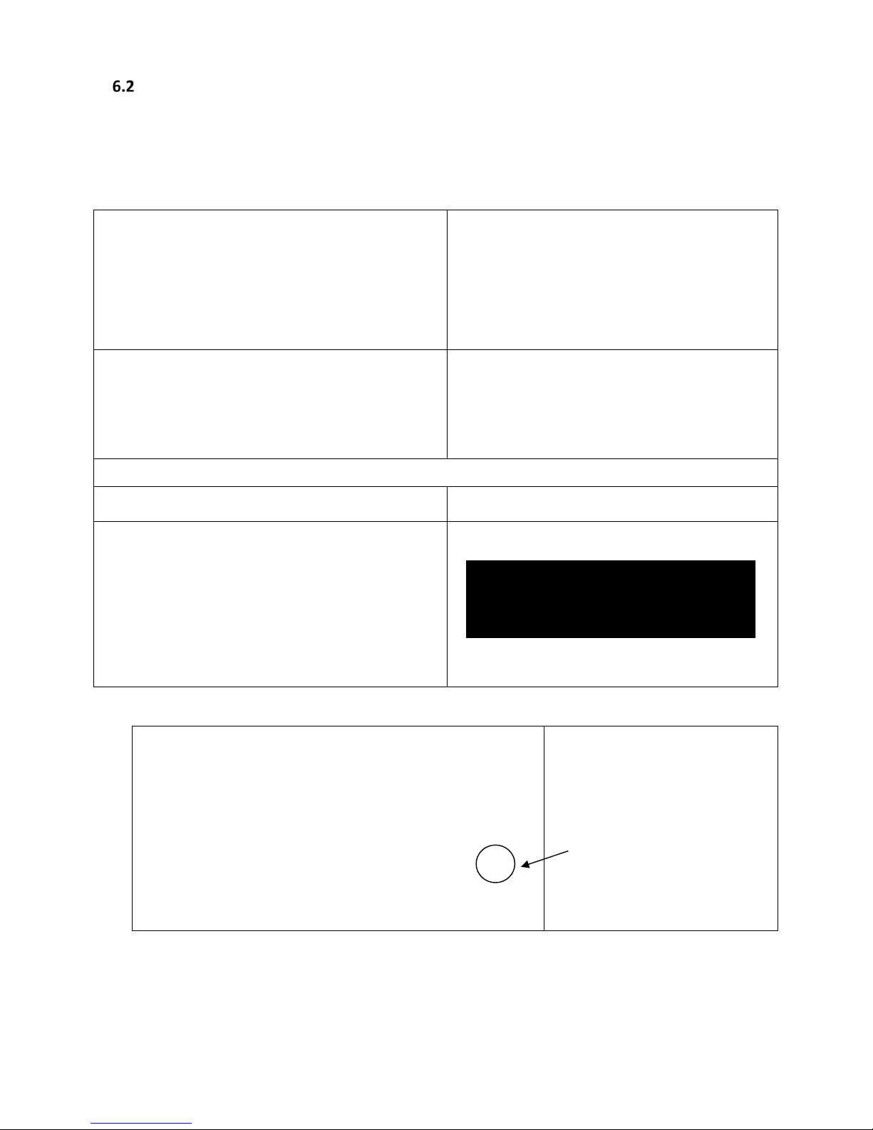
The display is located in the centre of the control panel. The main screen variants are presented
below. In the user manual, examples of screens from the Harrier R/RH are shown. For Harrier (without
refrigeration), the temperature is not shown. The flashing of field on display mean it is ready to set. The
flashing of fields is visualised as highlighted in the user manual.
After switching on of centrifuge, the welcome
screen will appear. On the next screen, it is then
possible to set up parameters.
Simplified display mode is set as default, it is
possible to switch to normal (see chapter 9.3)
display mode (with two sub modes shown
below).
Normal display
RPM display mode
o
RCF display mode
Switching between RPM and RCF display mode
For normal display,
switch between RPM and RCF
display mode by pressing and
holding the key for 1s:
then select demand
mode.
Page 21
21
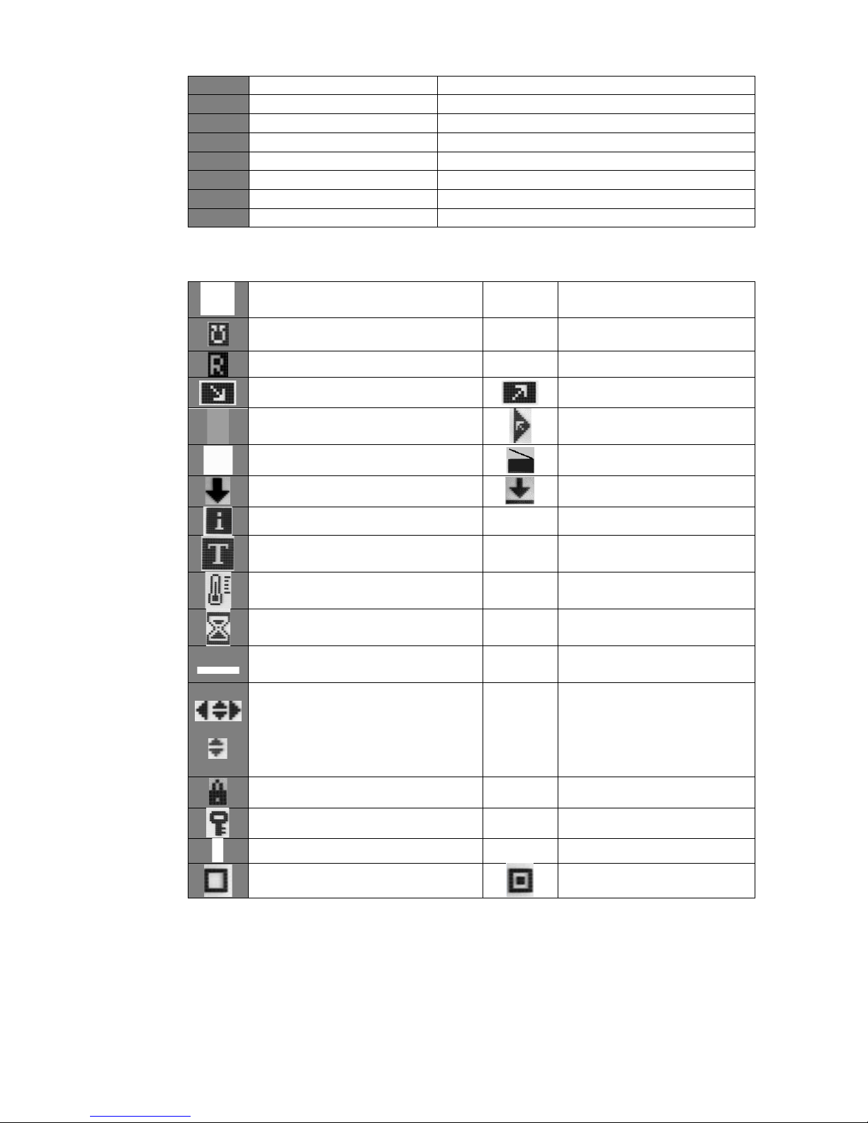
SPEED
rotor speed
assigned/measured
RCF
centrifugal force
assigned/measured
TIME
centrifuging time
assigned/measured
TEMP
temperature
assigned/measured
PRG
programme no.
11199
rotor no.
PARAM
parameters of the centrifuge
MENU
configuration menu
changing values
density > 1,2 g/cm3
centrifuging radius changed
counting time down (decreasing)
counting time up (increasing)
centrifuging
centrifuging
(with automatic cover opening)
rotor stopped / closed cover
rotor stopped / opened lid
braking
fastest decelerating
rotor identification
thermal chamber
temperature delay
time delay
currently enlarged digits of TIME
field
drop-down list
temporarily disabled
locked
time counting (flashing)
disabled option
active option
Page 22
22
Setting up RPM, RCF, time, temperature
On the main screen, it is possible to set:
rotating speed - RPM
SPEED
relative centrifugal force (multiple of g-force)
RCF
centrifuging time
TIME
centrifuging temperature
TEMP
Exemplary change of SPEED setting:
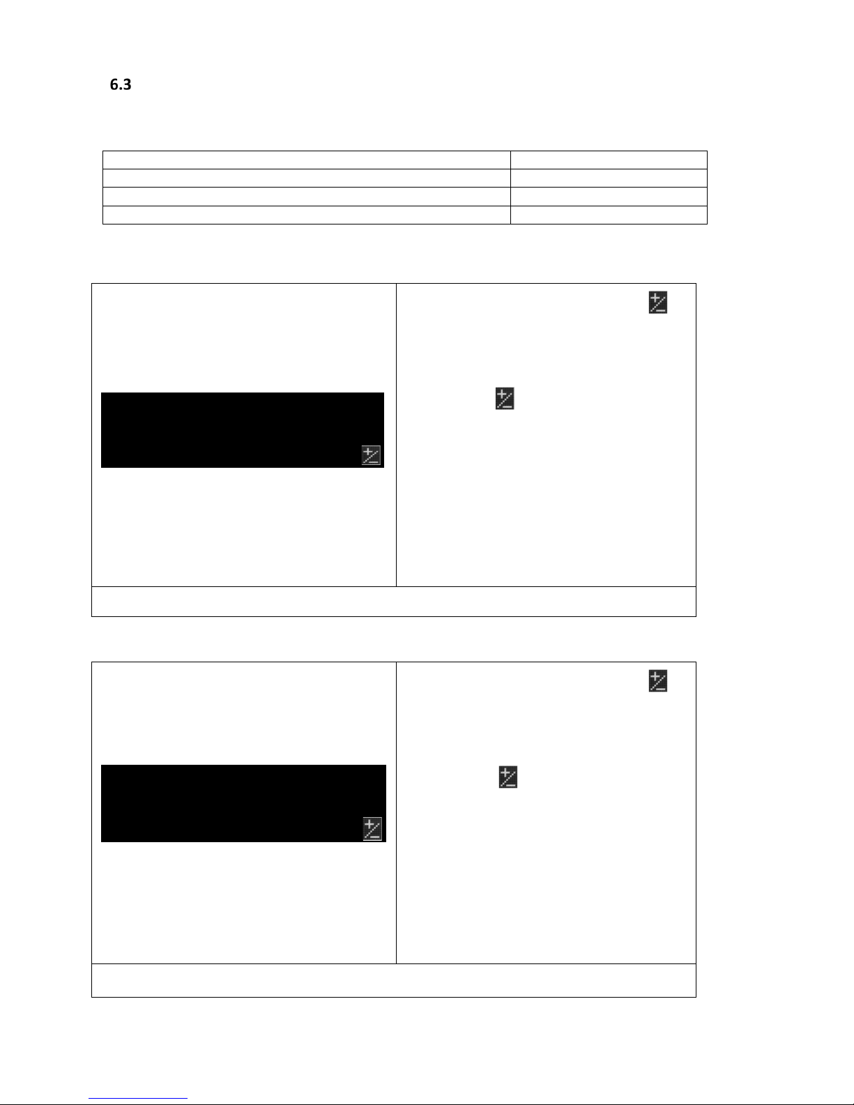
Press SET (to enter edit mode) –
appears.
Use ▲▼◄► keys to select SPEED
field (flashing).
Press SET- flashing.
With ▲▼ choose value.
Via
◄► choose order of magnitude of
changing value (highlighted).
Repeat above two steps for other
orders of magnitude.
Confirm settings by pressing SET.
Press BACK.
When RPM is changed, RCF is automatically corrected.
Change of RCF setting:
Press SET (to enter edit mode) –
appears.
Use ▲▼◄► keys to choose RCF field
(flashing).
Press SET- flashing.
With ▲▼
choose preferred value.
Via◄► choose order of magnitude of
changing value (highlighted).
Repeat above two steps for other
orders of magnitude.
Confirm settings by pressing SET.
Press BACK.
When RCF is changed, RPM is automatically corrected.
Page 23
23
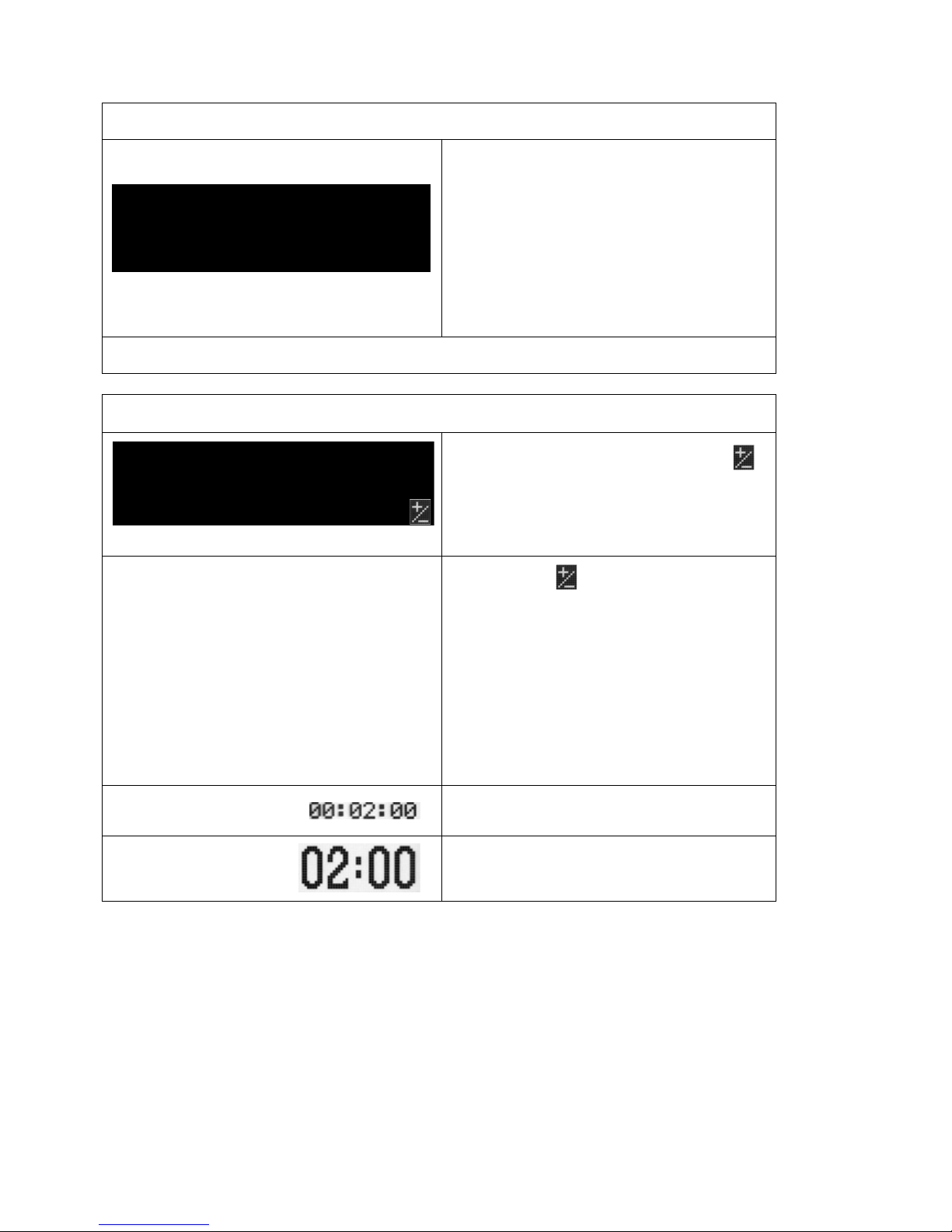
Switching between SPEED and RCF.
On the screen, there is an additional
window, in which you can select:
Use ▲▼ keys to select field .
Press SET.
Change of screen mode will be
active to switch off the centrifuge
Switching between basic and simplified screens is described in 9.3 Types of Main Screen
I
Change of TIME setting::
Press SET (to enter edit mode) -
appears.
Use ▲▼◄► keys to select TIME field
(flashing).
0 0 : 0 2 : 00
[hh : mm : ss]
e.g.:
centrifuging time – 2 minutes 00 seconds
Press SET - flashing.
With▲▼
choose preferred value.
Use ◄► to
choose order of magnitude
of changing value (highlited).
Repeat above two steps for other orders
of magnitude.
Confirm settings by pressing SET.
Exit edit mode by pressing BACK.
set value
current value (most significant digits)
Page 24
24
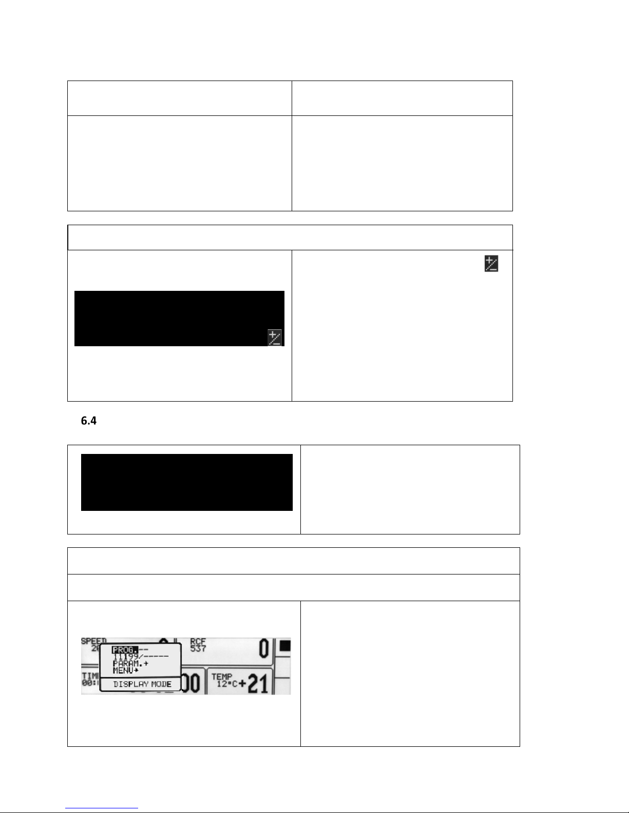
HOLD mode
continuous run mode
To run centrifuging in HOLD mode set
00:00:00 time.
To end centrifuging in HOLD mode press
STOP.
Change of TEMP setting:
Press SET (to enter edit mode) –
appears.
Use ▲▼◄► keys to select TEMP field
(flashing).
Press SET key.
With▲▼ choose preferred value.
Confirm settings by pressing SET.
Press BACK.
Users programmes
After switching centrifuge on, the
programme that was used in the previous
session will load automatically. If a
programme was not used in the previous
session, centrifuge will start with the last
choosen parameters.
Selecting a Programmen:
Simplified display mode
Press and hold
for 1 second.
Choose PROG with▲▼
Press SET.
Follow Normal display mode
(Normal Display Mode below)
Page 25

25
Normal display mode
Press SET key – appears.
Use ▲▼◄► keys to select PRG– –
field (highlighted)
Press SET key – list of programmes is
visible.
Use ▲▼ to choose preferred
programme.
Confirm with SET key.
LOAD, SAVE, DELETE, NEW PROGRAMME
Select NEW PROGRAM by pressing
.
SAVE – save settings as a programme
(confirm by selecting YES and pressing SET)
DELETE – delete programme (confirm by
selecting YES and pressing SET)
NEW PROGRAM – enter to create new
programme mode (as below)
Page 26

26
Creating a new programme:
Press SET key.
Use ▲▼◄► keys to select PROG field
(flashing).
Press SET key. List of programmes is
visible, choose preferred position
(number of programmes).
Press SET key- menu of programme
settings will appear.
Choose NEW PROGRAM press SET and
BACK, and then set chosen parameters
of centrifuging (refer to Chapter 6.
Centrifuging).
Changing parameters during centrifuging
There is a possibility to change parameters: SPEED, RCF, TIME, TEMP during centrifuging.
Such modifications inactivate the existing running programme. When programming i
s set,
modification during run is noted
by PROG – – symbol (instead of the programme number).
User multi-section acceleration/deceleration
features
CURVES – create acceleration or
deceleration features
Use
▲▼
keys to choose the saved
programme
for which you intend to
create the acceleration or deceleration
features (selected with symbol ).
Press SET.
With ▲▼ keys, choose CURVES.
Press SET -
the selection frame is
displayed.
Page 27
27
With
▲▼
keys, choose ACCELERATION
to create acceleration features or
DECELERATION to create deceleration
features
Confirm selection by pressing SET.
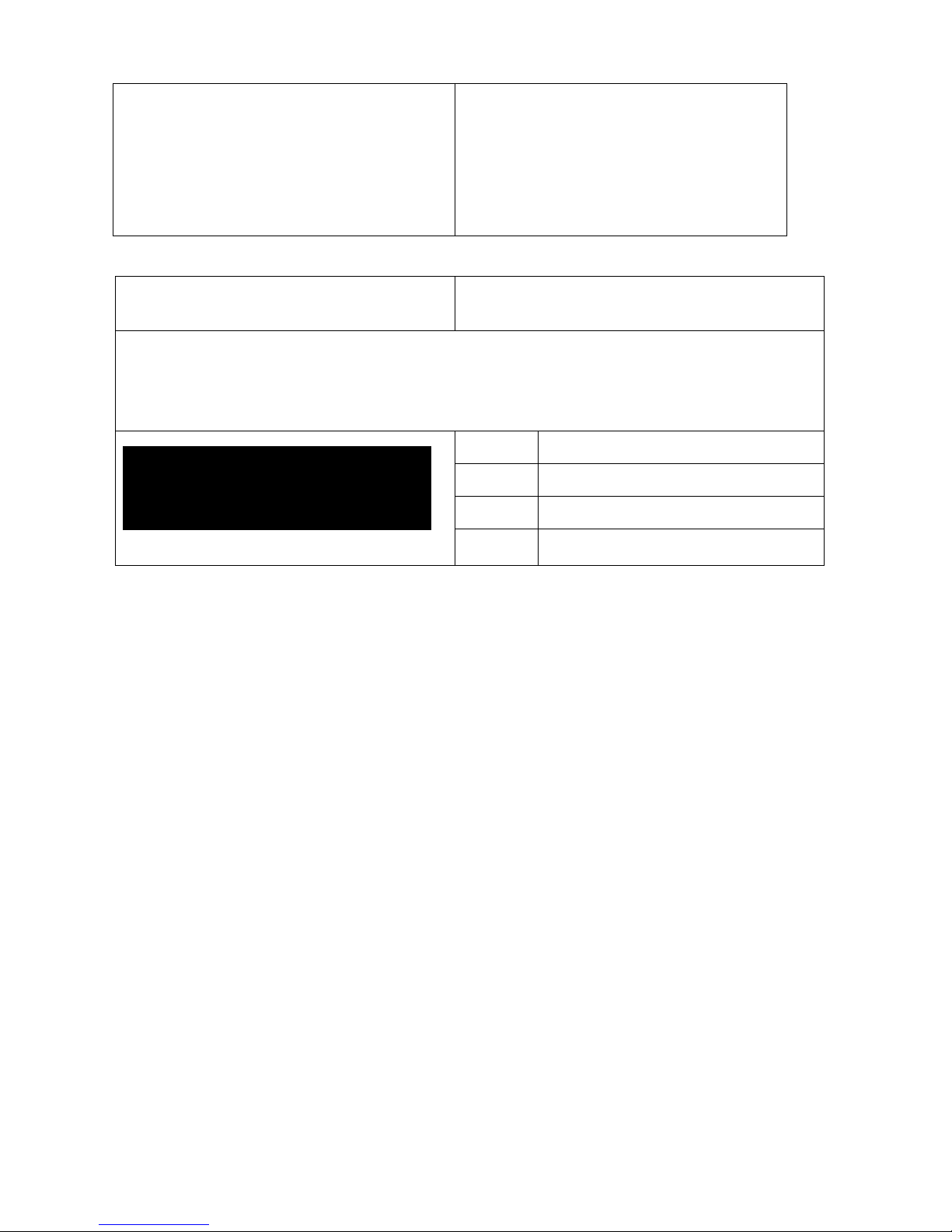
Acceleration features PROG / CURVES / ACCELERATION
After choosing PROG CURVES ACCELERATION the features wizard window will be displayed:
The current acceleration feature connected with the loaded programme
will be displayed on the
screen.
NO.
section no. (max. 4)
TIME
total acceleration time
SPEED
final RPM
ACC:12
feature’s no. (10-19)
If the EXIT field is selected, the message will flash. Pressing the SET key will cause a return to the PROG
CURVES fold, without making changes in the acceleration features. Press ▲ to start programming “1”
section.
„1” SECTION
Press SET.
With ▲▼ choose time for section, press SET.
With ▲▼ choose speed for section, press SET.
The set speed value is limited by the maximum speed of the rotor connected with the edited programme.
After the programming of the speed, graphical display of the section (of all sections) will occur
TIME+SPEED of the user's acceleration features.
After programming section 1, there is a possibility to programme the next section, number 2:
Page 28

28
„2” SECTION
Programming of new section (the whole line 2 is
flashing). Programming as in section 1. It is also
possible to abandon the programming: with
UP/DOWN keys choose the EXIT option (it will
flash) and then save (press the SET).
Acceleration features will be as section 1 with
TIME/SPEED parameters described in line 1.
The minimal speed of acceleration will be equal to the last speed programmed.
„3” SECTION
Programming of a new section is possible (when
the whole line 3 is flashing). Programming as in
section 1. It is also
possible to abandon the
programming: with ▲▼ keys, choose the EXIT
option (it will flash) and save (press SET)
Acceleration features will be as section 2 with
TIME/SPEED parameters described in lines 1 and
2.
„4” SECTION
Programming of a new section is possible (when
the whole line 4 is flashing). Programming as in
the case of section 1. It is also possible also to
abandon programming: with
▲▼ keys choose
the EXIT option (it will flash) and save (press SET)
Acceleration features will be as section 3 with
TIME/SPEED parameters described in lines 1, 2
and 3.
Repeated attempts to programme previously programmed sections of the acceleration features will cause
beginning of programming of the whole acceleration features once again (with settings of the programme
loaded to edition – factory setting).
Page 29
29
Deceleration feature: PROG / CURVES / DECELERATION
After choosing PROG CURVES DECELERATION, the window of the features’ wizard will be displayed:
Default deceleration features connected with the loaded programme will be displayed on the screen.
Creating of deceleration features takes place differently than acceleration features.
NO.
section no. (max. 4)
TIME
total acceleration time
SPEED
final RPM
DEC:10
features no. (10-19)
First press EXIT field (the message is flashing). Pressing the SET key will revert to the PROG CURVES,
without making changes in the deceleration features. Press ▲ to start programming “1” section.
„1” SECTION
Press SET.
With ▲▼ choose time for section, press SET.
With ▲▼ choose speed for section, press SET.
In order to compete the creation of the deceleration curve, it is necessary for the speed of the last of
programmed sections of the curve to be equal = 0. Otherwise the curves wizard will not enable the end
of programming (it will be impossible to select the EXIT option).
After programming the section 1, there is a possibility to programme the next section, number 2. You can
opt out of the following sections by pressing EXIT.
„2” SECTION
New section programming possible (the whole line 2
is flashing). Programming as in section 1. To stop
creating the deceleration curve at the stage of two
sections, it is necessary to set the speed in section 2
to 0 and press the SET key and then choose EXIT and
press SET.
The maximum speed of the next section of deceleration feature is equal to the pre-programmed speed of
the previous section.
„3” SECTION
New section programming possible is (when the
whole line 3 is flashing). Programming as in section
1. To stop creating the deceleration curve, it is
necessary to set the speed in section 3 to 0 and
press the SET key and then choose EXIT and press
SET.
Page 30

30
„4” SECTION
New section programming is possible (when the
whole line 4 is flashing). Programming as in the case
of the section 1. If speed of the last section=0, it is
possible to save the created features by choosing
the EXIT option with
▲▼ keys and pressing the SET
key and then choose EXIT and press SET.
Repeated attempts to programme, pre-programmed sections of the acceleration features will cause a
reset of the whole deceleration features (with settings of the programme loaded to edition, factory
settings).
Programmes with user features
Loading a modified programme in the CURVES folder is signalled? by the icon on the main screen:
Icon signals that programme
with user
acceleration/deceleration features is loaded.
It is not possible to change parameters (speed, rotor no. and others) during a run, when a programme with
user feature is loaded. However, changing these parameters is possible in PARAM/ ACCELERATION,
PARAM/DECELERATION.
Rotor selection
Simplified display mode
Press and hold
for 1 second.
Choose rotor number
(exemplary 11199/-----) with▲▼.
Press SET.
Follow instructions below (below Normal
display mode description)
Normal display mode
Press SET– appears.
Use ▲▼◄► to select rotor choosing field.
Page 31
31
Press SET (Rotor list will appear).
Use ▲▼keys to select chosen rotor number
Confirm by pressing SET.
Press BACK.
It is possible to set AUTOMATIC ROTOR IDENTIFICATION.
The procedure is described in subsection 9.8.
SHORT mode
The SHORT mode is activated by pressing and holding ► ► (SHORT).
In SHORT mode, the centrifuge is working as long as the SHORT key is
pressed or when set time is over.
Finishing the centrifuging
When preselected time is reached, centrifugation will end automatically.
X1
Before preselected time is completed, it is possible to stop centrifugation.
Pressing STOP for the first time will stop centrifuging with the features set in loaded
programme. symbol will be shown.
x2
Pressing STOP for a second time will stop centrifuging with the fastest
feature. symbol will be shown.
The message about cancelling of centrifuging can be deleted with the STOP, SET, COVER,
▲▼◄► or BACK key.
Page 32
32
7 Temperature control
Harrier R and Harrier RH only
The centrifuge is equipped with ecological refrigerating system with temperature control.
During centrifugation, differences in temperature may appear on the display and temperature of the
samples in the rotor. This depends on the thermal conductivity of the rotor, samples and
centrifugation time, initial temperature of rotor and samples.
Change of TEMP setting:
Press SET (to enter edit mode)
–
appears.
Use ▲▼◄► keys to select TEMP field
(flashing).
Press SET key.
With▲▼ choose preferred value (from -
20
o
C to 40oC).
Confirm settings by pressing SET.
Press BACK.
Cooling is indicated by this symbol
(flashing).
Initial cooling during centrifuging – FAST COOL
The parameters available to change at FAST COOL mode:
temperature (lower than current temperature shown by centrifuge)
In order to centrifuge reduced temperature samples (eg. storage in the
external refrigerator), centrifuge chamber, rotor and centrifuge container
must be pre-cooling to the predetermined temperature. It may cause
minimalization of temperature differences.
Initial cooling may be activated by FAST COOL key (lid must be closed –
rotor is spinning at FAST COOL mode)
When FAST COOL mode is active, the cooling system will automatically set
the parameters needed to obtain the requested temperature the quickest.
Page 33
33
FAST COOL mode is selected by symbol
flashing in the right upper side of
display.
It is possible to exit FAST COOL mode at any
time by pressing STOP key.
Interruption of the function is signaled by
a message.
Initial cooling or heating without centrifuging – THERMAL CHAMBER
PARAM THERMAL CHAMBER
0 RPM
It is possible to run the centrifuge in THERMAL CHAMBER mode - cooling
for R, cooling and heating for RH (rotor is at standstill).
How to enable THERMAL CHAMBER is described in Parameters of
centrifugation chapter.
Cooling or heating in “START DELAY – OF TEMPERATURE” mode
PARAM START DELAY – OF TEMPERATURE
2500 RPM
Centrifuging process will start, when preselected temperature is reached.
How to enable run START DELAY – OF TEMPERATURE function is described
in Parameters of centrifugation chapter.
Cooling or heating in „SHORT” mode
Cooling and heating features are available in SHORT mode.
How to enable run centrifugation in SHORT mode is described in
Centrifugation/SHORT mode.
Cooling and heating notes
Centrifuges with cooling (HARRIER R and HARRIER RH) are equipped with an efficient cooling
system. It allows for the desired temperatures in the chamber even at maximum spin speed or fast to
be reached quickly (e.g. 4⁰C and 36⁰C). Note that the amount of time needed to reach a set
temperature is dependent on multiple factors, including: the power of the cooling system, the shape
of the rotor, the rotor speed, ambient temperature, etc. The accuracy of the temperature stability of ±
1 ⁰ C is determined by the installation place of the temperature sensor.
Page 34
34
8 Parameters of centrifugation
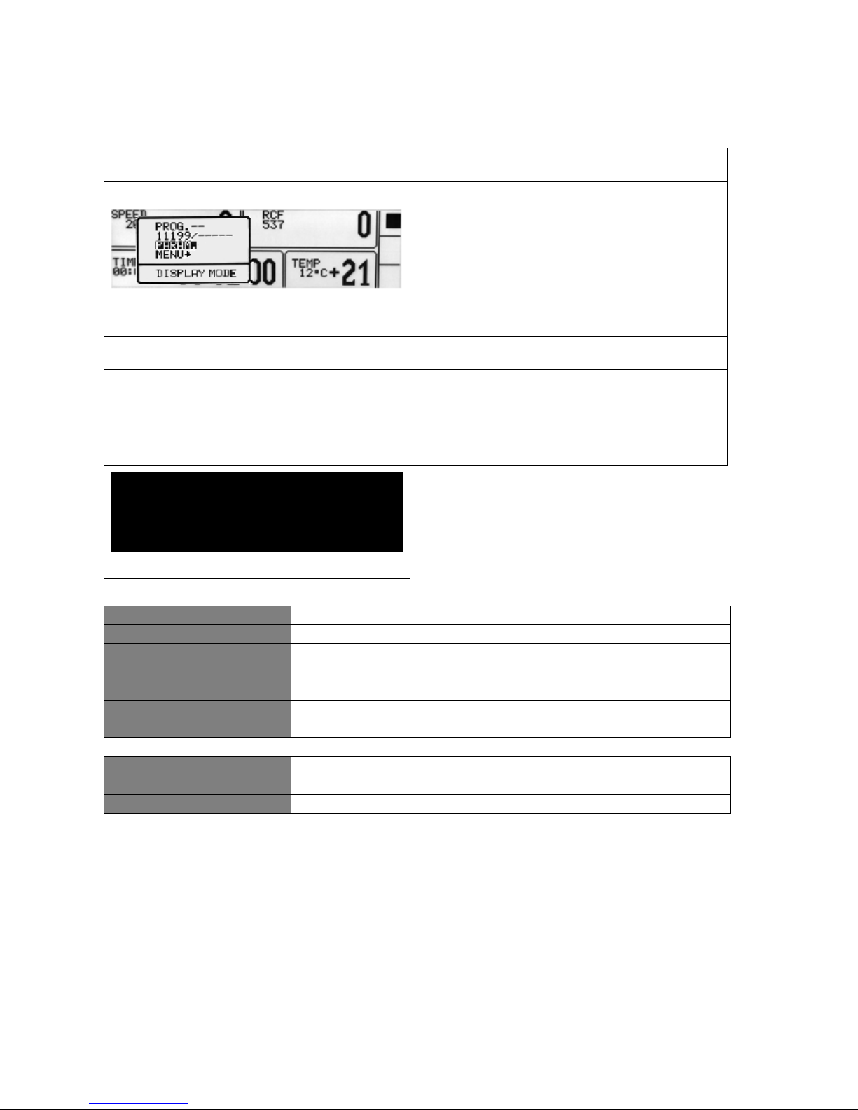
Simplified display
Press and hold
by 1 second.
Choose PARAM. with▲▼
Press SET.
Follow points descripted below (Normal
display mode description)
Normal display
Press SET.
With ▲▼◄► keys select PARAM.
Press SET.
ACCELERATION
chosen acc. feature (0-the fastest, 9-the slowest)
DECELERATION
chosen dec. feature (0-the fastest, 9-the slowest)
RADIUS [mm]
current rotor radius [mm]
DENSITY (g/cm3)
sample density [g/cm3]
TEMP. OFFSET (OC)
value of temperature correction
CHAMBER DEL. (min) delay between set thermal chamber mode and start
THERMAL CHAMBER
cooling of the chamber without centrifuging
AUTOM. LID OPENING
automatic opening of cover after centrifuging
START DELAY
delay start (after pressing START)
Page 35
35
Acceleration/deceleration – changing features
With ▲▼ keys select ACCELERATION or
DECELERATION.
Press SET.
With ▲▼ keys select requested number
of feature.
Press SET.
ACCELERATION –10 (0 ÷ 9), linear
accelerating features assigned to every
rotor. 0-the fastest acceleration, 9-the
slowest acceleration.
DECELERATION – 10 (0 ÷ 9), linear
decelerating features assigned to every
rotor. 0-the fastest deceleration, 9-the
slowest deceleration.
Radius
RADIUS [mm] - control of the radius
of the rotor within the range from R
min
to
R
max
. Available values depends on chosen
rotor.
To change the rotor radius select
RADIUS [mm] with ▲▼ keys.
Press SET.
Set requested value by pressing ▲▼.
When change of radius
is activated,
symbol is visible on the
screen.
Reducing of the rotor radius (and the
resulting change of displayed RCF value)
applies until switching off of
the power
supply of the centrifuge or setting the Rmax
maximum radius once again (loading the
programme does not change this setting!).
Sample density
DENSITY (g/cm
3
)) – default density is set
to 1,2 g/cm3
To change the density (value range:
1,2÷9,9 g/cm
3
):
Via ▲▼ keys select DENSITY (g/cm
3
))
Page 36
36
Press SET.
Set requested value by pressing ▲▼.
Press SET.
When density is changed, symbol
is visible on the screen.
Changing of DENSITY value is compulsory
when density of sample placed into rotor
is higher than 1.2 g/cm
3
. Change of
DENSITY value leads to a lower maximum
speed value.
Temperature offset
With▲▼keys select TEMP. OFFSET.
Press SET.
Use the ▲ ▼ keys to select the difference
between the temperature that the cooling
system will aim for, and set temperature.
Confirm selection by pressing SET.
Warning!
The use of the offset cannot extend the
temperature range achieved by the
centrifuge.
Function description
At a set temperature of 20
o
C and the set
offset value equal to -5oC, the cooling system
will actually strive to reach 15
o
C. With a
setpoint temperature of 20oC and a set offset
value of 5
o
C, the system will actually try to
reach 25
o
C.
The temperature disp
layed on the main
screen is corrected for offset value.
Offset can be selected range from -20oC to
20
o
C.
Activation of the function is signalled on the
main screen with or depending on
the offset value sign.
Page 37
37
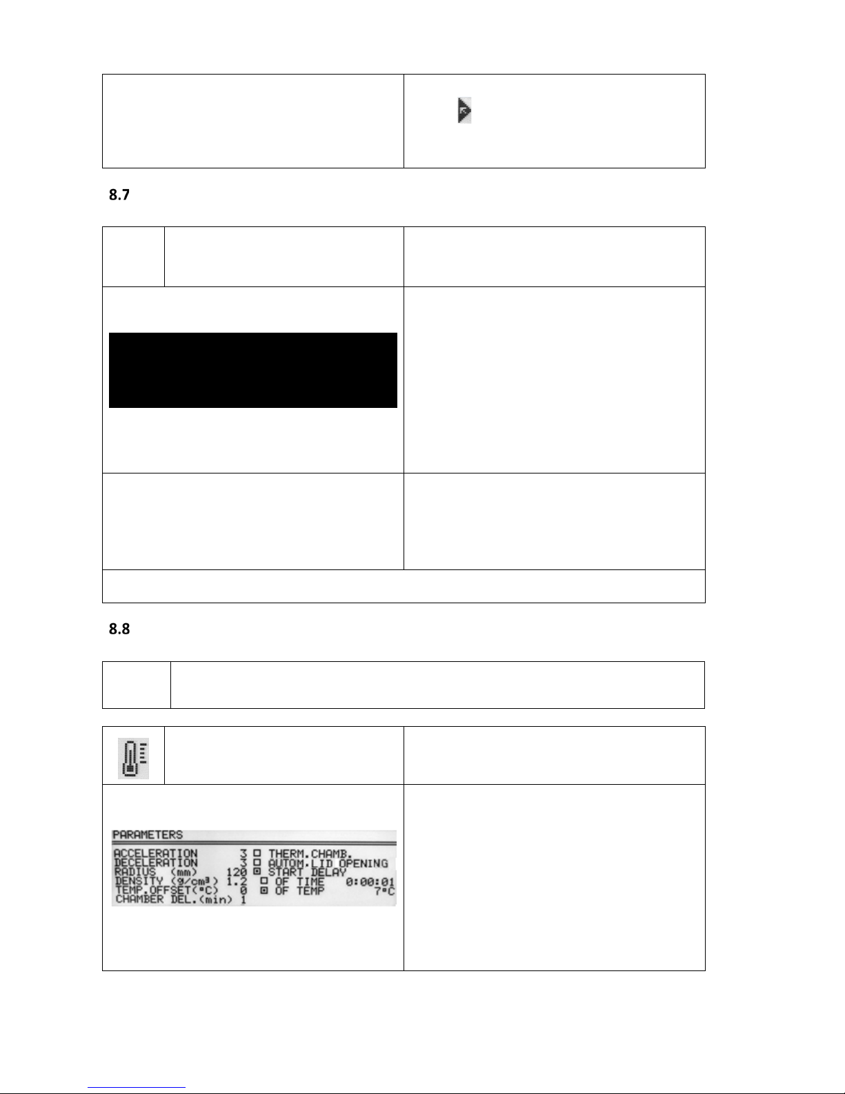
Thermal chamber
HARRIER R and HARRIER RH only
without centrifuging
THERMAL CHAMBER
With ▲▼◄► keys select THERMAL
CHAMBER.
Press SET (to turn on/off).
With ▲▼ keys select temperature value.
Set demanded value by pressing ▲▼.
When THERMAL CHAMBER function is
activated,
symbol is visible on the
screen.
Changing temperature from the main
screen is not possible.
Opening cover terminates THERMAL
CHAMBER
function (closing cover back
turns it on).
If THERMAL CHAMBER is turned on (in PARAM) and centrifugation completes,
THERMAL CHAMBER will activate itself.
THERMAL CHAMBER can be only activated when no other programmes are running.
Automatic lid opening
Automatic lid opening
AUTOMATIC LID OPENING
When centrifuge process is finished,
cover will be opened automatically.
When centrifuging is terminated by
pressing STOP, the opening of teh cover
is possible by pressing COVER.
Page 38
38
this symbol means that
OPEN LID
AFTER RUN has been activated.
Start delay - of time
Start centrifuging since
preselected delay is reached.
START DELAY / OF TIME
With ▲▼ keys select START DELAY.
Press SET.
Start delay can be set from
0 : 0 0 : 0 1 to 9 : 5 9 : 5 9.
With ▲▼ keys select OF TIME. Press ►
and then SET.
With ▲▼ keys set requested value.
Confirm by pressing SET.
When START DELAY function is activated,
symbol is visible on the screen.
START DELAY / OF TIME function cannot be run when START DELAY / OF TEMP is activated.
Start delay – of temperature
HARRIER R and HARRIER RH only
Start centrifuging after preselected
temperature is reached.
START DELAY / OF TEMP.
With ▲▼ keys select START DELAY.
Press SET.
Start delay can be set from
0 : 0 0 : 0 1 to 9 : 5 9 : 5 9.
With ▲▼ keys select OF TEMP. Press ►
and then SET.
With ▲▼ keys set requested value.
Confirm by pressing SET.
Page 39
39
When START DELAY – OF TEMPERATURE
is turned on, symbol is visible on the
screen.
When the function is active, the speed can be reduced to the optimum values for the
FAST COOL function, when the set speed is lower than the optimum value, the rotor
rotates at the set speed.
START DELAY / OF TEMP. function cannot be run when START DELAY / OF TIME is activated.
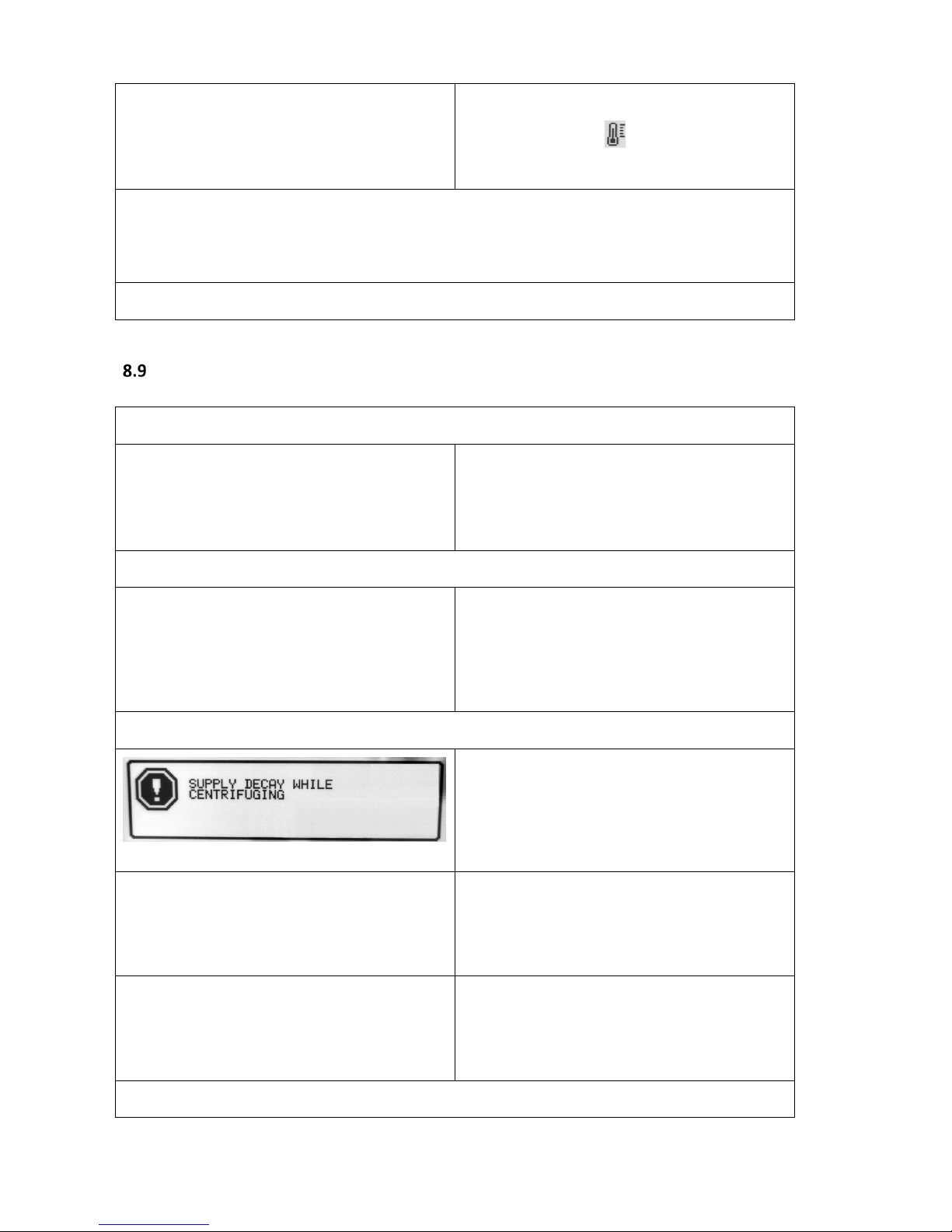
Screen messages
End of centrifuging – manual mode
Centrifuging may be stopped at any moment via
the STOP key. The information message: CYCLE
CANCELLED will be displayed.
End of centrifuging – normal mode
Stopping centrifuging in accordance with the set
time will cause multi-ton audible signals (after
stopping the rotor) and displaying of the
following message:
FINISH OF CENTRIFUGING
Additional messages
In case of power shortage while centrifuging, the
following error screen will be displayed:
SUPPLY DECAY WHILE CENTRIFUGING
Identified number of the installed rotor is not
compatible with the rotor number preprogramme.
Rotor is braking (only when
centrifuge was
switched off during rotor running).
After pressing SET or STOP, the main screen will display.
Page 40

40
Page 41

41
Screen messages that may occur during operation.
MESSAGE
EXPLANATION
"SPEED OF ROTOR"
"IDENTIFICATION <> 90 RPM"
SPEED OF ROTOR IDENTIFICATION <> 90 RPM
"IMBALANCE FAST STOP !"
"PLEASE REMOVE CAUSE"
"THEN RESTART"
IMBALANCE DETECTED
"NO ROTOR OR IDENTIFICATION"
"SENSOR DAMAGED !"
ERROR OF ROTOR IDENTIFICATION {LIMIT OF 6SEC. IS OVER}
"INCORRECT ROTOR NUMBER !" ROTOR’S ID NOT CORRECT
"WRONG DIRECTION OF ROTATION"
"OR UNKNOWN ROTOR !"
WRONG DIRECTION OF ROTATION / UNKNOWN ROTOR
"PLEASE CLOSE THE LID"
"HAND !"
CLOSING THE LID MANUALLY
"ROTOR STOPPING !"
"Please wait..."
INITIALIZING AFTER MAINS FAILURE WITH ROTATING
ROTOR
" CYCLE'S ABORTED !" CENTRIFUGING ENDED DUE TO PRESSING STOP
" CYCLE'S FINISHED" CENTRIFUGING ENDED {WITHOUT ERRORS}
Page 42

42
Emergency messages
In case of emergency messages (centrifuge is not working properly) contact the manufacturer's authorised service centre.
MESSAGE
EXPLANATION
"OVERHEATING MOTOR !"
"INVERTER ERROR !"
"OVERHEATING MOTOR !"
"INVERTER ERROR !"
"INVERTER SERIAL BUS ERROR !" "INVERTER SERIAL BUS ERROR !"
"TEMPERATURE SENSOR ERROR" "TEMPERATURE SENSOR ERROR"
"PRESSURE CONTROL FAILURE!" "PRESSURE CONTROL FAILURE!"
"OPENING COVER in RUN!" "OPENING COVER in RUN!"
"SPEED METER ERROR" "SPEED METER ERROR"
"I2C BUS ERROR" "I2C BUS ERROR"
"OVERHEATING CENTRIFUGE !" "OVERHEATING CENTRIFUGE !"
"ROTOR OVERSPEED !" "ROTOR OVERSPEED !"
"COVER LOCK MALFUNCTION !" "COVER LOCK MALFUNCTION !"
Page 43
43
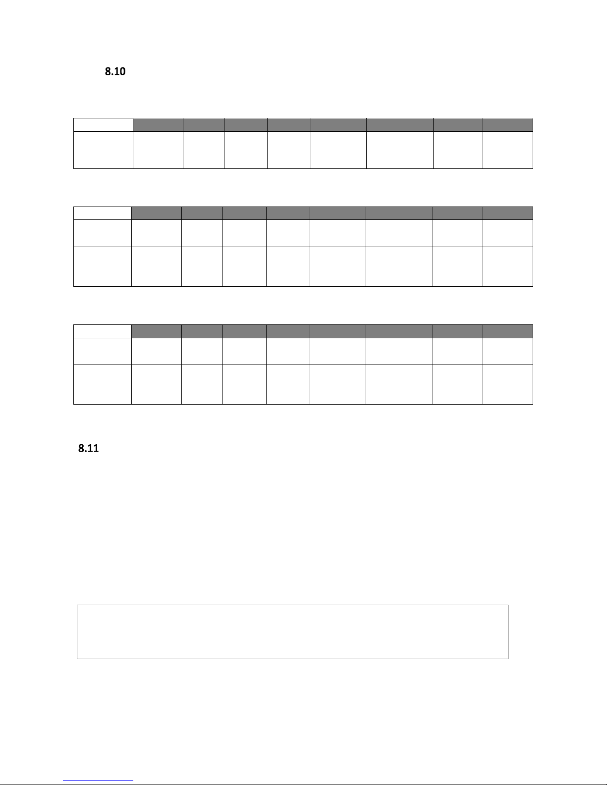
Temporarily disabled functions
The functions below can be temporarily disabled.
active
SPEED
RCF
TIME
TEMP
PROG ––
––––– / ––––
PARAM
MENU
THERMAL
CHAMBER
● ● ● ○ ● ● ●
●
During run
active
SPEED
RCF
TIME
TEMP
PROG ––
––––– / ––––
PARAM
MENU
PROG 99
○ ○ ○ ○ ○ ○ ○
●
ACC/DEC
10-19
○ ○ ● ● ○ ○ ●
●
Standstill
active
SPEED
RCF
TIME
TEMP
PROG ––
––––– / ––––
PARAM
MENU
PROG 99
○ ○ ○ ○ ● ○ ○
●
ACC/DEC
10-19
○ ○ ● ● ● ○ ●
●
● available
○ disabled
Unbalance
The centrifuge is provided with the rotor unbalance sensor and when it is activated, centrifugation
process will be stopped through fast braking and at the same time, an error message will be displayed.
Cancellation of this error is only possible through pressing the BACK key after the rotor has stopped.
Once the rotor is correctly loaded, close the cover and re-start the programme. In order to protect
the rotor against incorrect work, it has to be provided with identically filled buckets, carriers, test-tubes etc.
for getting the best balance possible (see section 4.3).
Then close the cover and restart the programme.
Unbalance causes noise and vibrations during operation, and adversely affects power
transmission system (motor, shock absorbers). The better balance, the smoother the
centrifuge operation and therefore the longer life of the machine.
Page 44

44
Emergency stop
At any time during centrifuging, it is possible to interrupt the process and fast stop the rotor. Singletime pressing of the STOP key will make centrifuging stop with the acceleration features set in the
programme (after pressing either SET or STOP keys, the device returns to the main screen). Pressing and
holding it up to 1s will make the centrifuging stop with the strictest feature.
Page 45
45
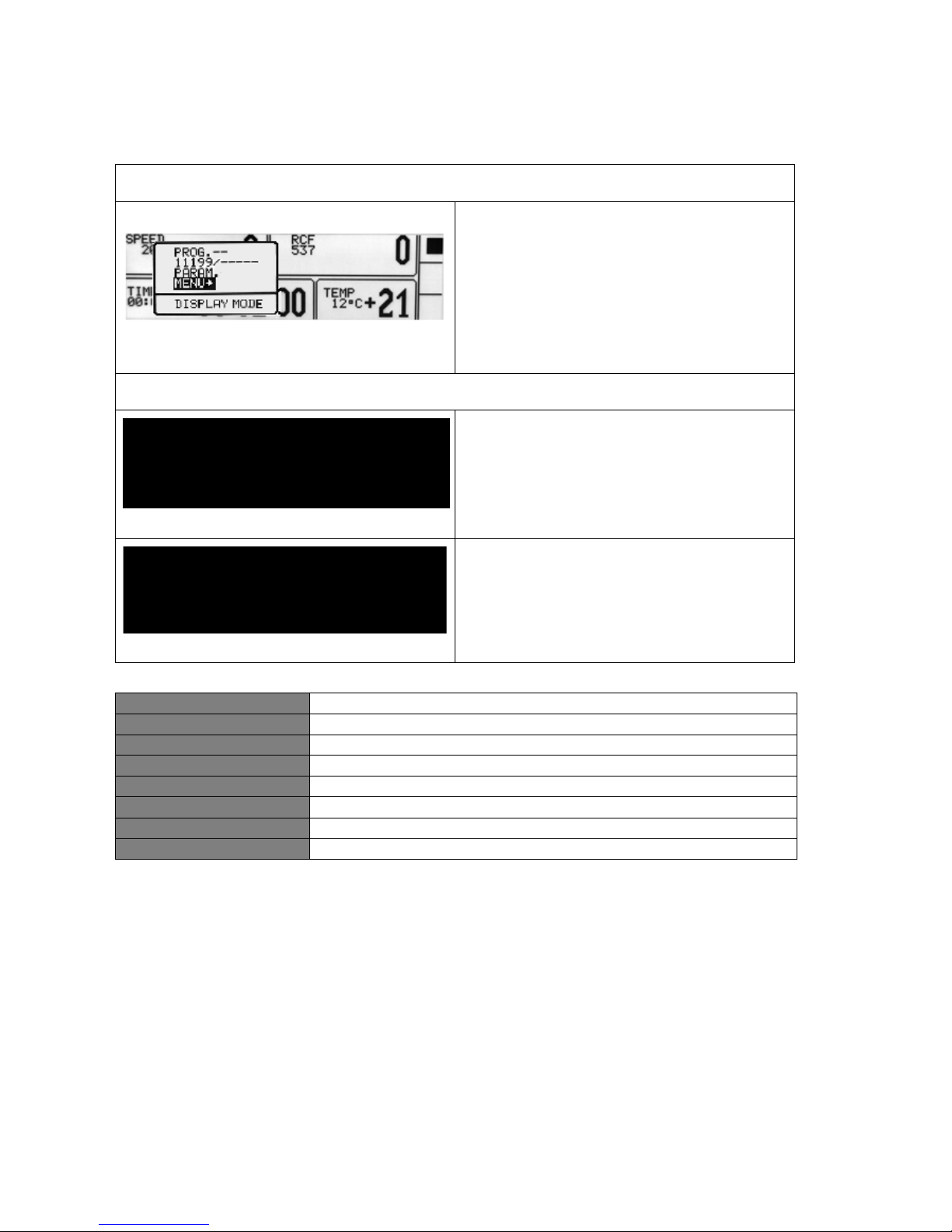
9 Menu
Simplified display
Press and hold
by 1 second.
Choose MENU with▲▼
Press SET.
Follow points described below (Normal
display mode description)
Normal display
Press SET.
With ▲▼◄► keys select MENU.
Press SET.
To navigate in MENU use ▲▼◄► keys.
To enter menu press SET.
CONFIGURATION
centrifuge configuration
PASSWORD
password protection
LAST 10-CYCLES
10 last centrifugation cycles history
CYCLES
total working time, working cycles counter
ROTOR RUNTIME
counting time for each rotor
CONTACT US
manufacturer’s details
DIAGNOSTICS
error codes (service field)
FACTORY SETTINGS
restore factory settings
Page 46
46
Screen saver
Setting time of screen saver
MENU/ CONFIGURATION / SCREEN
With ▲▼◄► keys, select
SCREENSAVER.
Press SET and then ▼ .
With ▲▼ keys select demanded value
from 1 to 60 minutes.
Select selection by pressing SET.
Leave the menu by pressing BACK.
Visual alarm
Visual alarm
CONFIGURATION/ SCREEN
Via
▲▼
keys choose VISUAL ALARM
Select it by pressing SET.
VISUAL ALARM causes the screen
to flash
after the end of centrifuging or after an
error.
Types of main screen
Default setting is SIMPLIFIED DISPLAY.
To switch to NORMAL DISPLAY, follow the rules in section 9.3.2.
Types of main screen
NORMAL DISPLAY
SIMPLIFIED DISPLAY
9.3.1 Switching the normal display to simplified display
Press the BACK button for 1 sec. then:
Page 47
47
Via
▲▼
keys select SIMPLIFIED DISPLAY.
Press SET.
9.3.2 Switching the simplified screen to normal display
Press the BACK button for 1 sec. then:
Via
▲▼
keys select DISPLAY MODE
(flashing).
Press SET.
Then choose NORMAL DISPlAY and press
SET.
Rotating runtime
Way of time counting
MENU/CONFIGURATION/ ROTATING RUNTIME
Via
▲▼ choose demanded option.
Select it by pressing SET.
Counting from:
Pressing start
COUNTING SINCE ROTOR IS IDENTIFIED
Reaching speed
COUNTING FROM ASSIGNED SPEED
Presenting mode:
Descending
COUNTING DOWN
Ascending
COUNTING UP
Page 48

48
Buzzer
Switching ON/OFF short audible signals
accompanying every pressing of any key.
MENU/ CONFIGURATION /BUZZER
With ▲▼ keys select demanded option.
Select selection by pressing SET.
Warning signals are always switched on.
Date/time
Setting up time and date
MENU/ CONFIGURATION /DATE/TIME
Via keys ◄► select DATE/TIME field
(flashing).
Press SET.
Via
◄► keys choose requested value.
Via
▲▼ keys change choosen value.
Confirm by pressing SET.
Repeat above steps for other values.
Press BACK.
Set date and time are still active even after restart of centrifuge.
Language
Changing menu language
MENU / CONFIGURATION / LANGUAGE
Via▲▼ keys choose menu language
Select it by pressing SET.
Page 49
49
Other
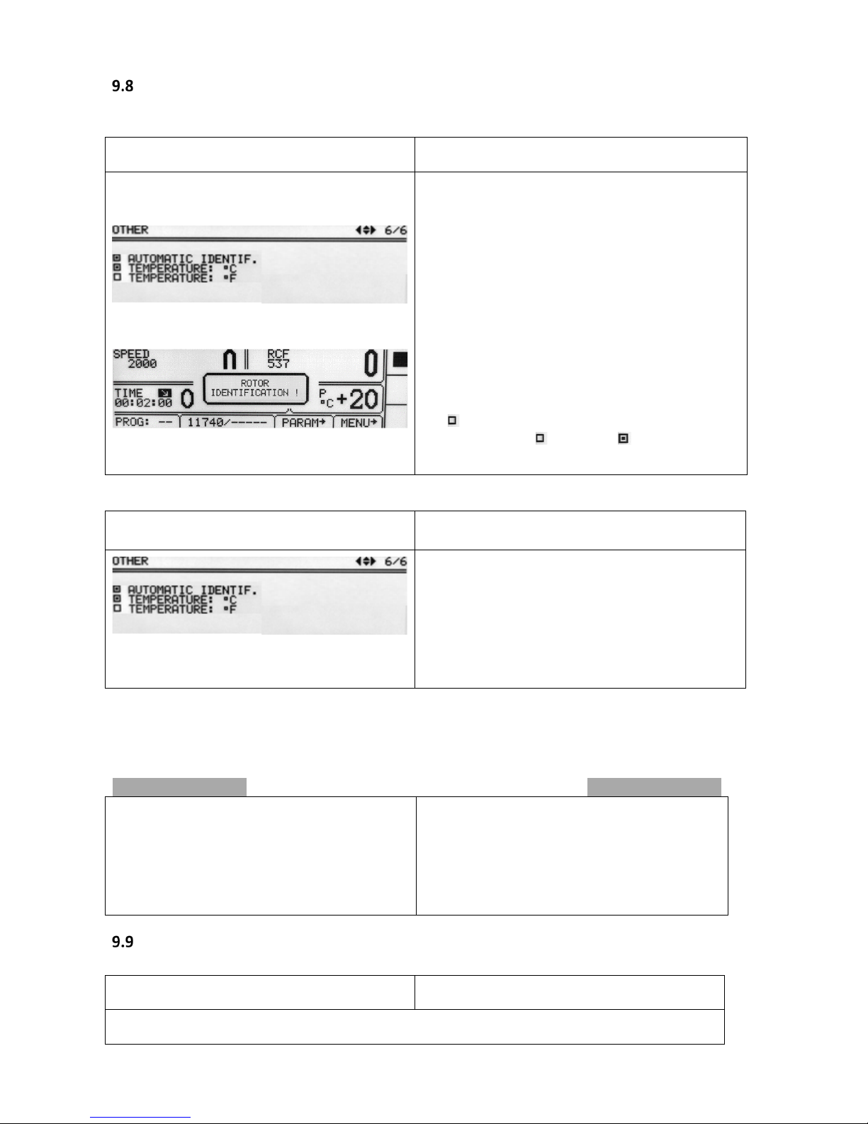
Rotor automatic identification
MENU / CONFIGURATION / OTHER
Thanks to the automatic rotor identification, the
centrifuge automatically identifies the rotor in the
chamber. Rotor identification is indicated by the
message.
When the function is deactivated, it is necessary to
manually select the desired rotor as described in
"6.7 Choosing rotors".
The AUTOMATIC IDENTIF. is turned on by default.
To enable the function:
Via
▲▼ keys choose
AUTOMATIC IDENTiF.
Press SET ( change to ).
Choice of temperature unit MENU / CONFIGURATION / OTHER
The TEMPERATURE in °C is turned on by default.
To change the temperature unit:
Via
▲▼ keys select unit
Confirm by pressing SET.
TEMPERATURE IN °C
TEMPERATURE IN °F
Password
Setting up password
MENU / PASSWORD
To prevent from unauthorised use, a PASSWORD can be set.
Page 50

50
Note: No PASSWORD is set by default.
The PASSWORD can be set as follows when the rotor is at a standstill.
Press the
▲▼
keys until “PASSWORD:”
blinks.
Press SET.
Press ►
With
◄► keys set the PASSWORD. With
▲▼ keys set correct value.
Repeat above steps for all places.
Press SET.
As a confirmation,
repeat instructions
described above.
When the PASSWORD is set, the Key sign is displayed in the CODE zone. It is also displayed in the
main menu (lower right corner of the screen).
From then on, access to the MENU is only possible after entering the password.
In case of incorrect password, it will show message: ACCESS DENIED!
Page 51
51
To delete the PASSWORD, “0000” must be set.
If the PASSWORD is forgotten, the emergency code “7654” should be used to clear password and
remove all locks.
Setting up locks
With
▲▼
keys choose a lock.
Select a lock by pressing SET.
Repeat above steps for desired locks.
Leave menu with BACK key.
Disabled* description
SAVE PROGRAM SAVE button
no programmes can be saved
DELETE PROGRAM
DELETE button
no programmes can be deleted
saving a programmes where one
was already stored is disabled
CHANGE PARAMETERS
fields:
SPEED
RCF
TIME
TEMP
PROG––
––––– / –––––
PARAM
PROG
parameters cannot be modified
LOAD PROGRAM LOAD button
no programmes can be called up
START KEY START key
centrifugation cannot be started
* Executing disabling procedures is only possible after entering the correct password
Page 52
52
Last 10 cycles
Information concerning parameters of last
10 centrifuging cycles.
MENU / LAST 10 CYCLES
Number of cycle can be changed by ◄►
keys.
The list can be scrolled using ▲▼ keys.
To exit press SET/BACK key
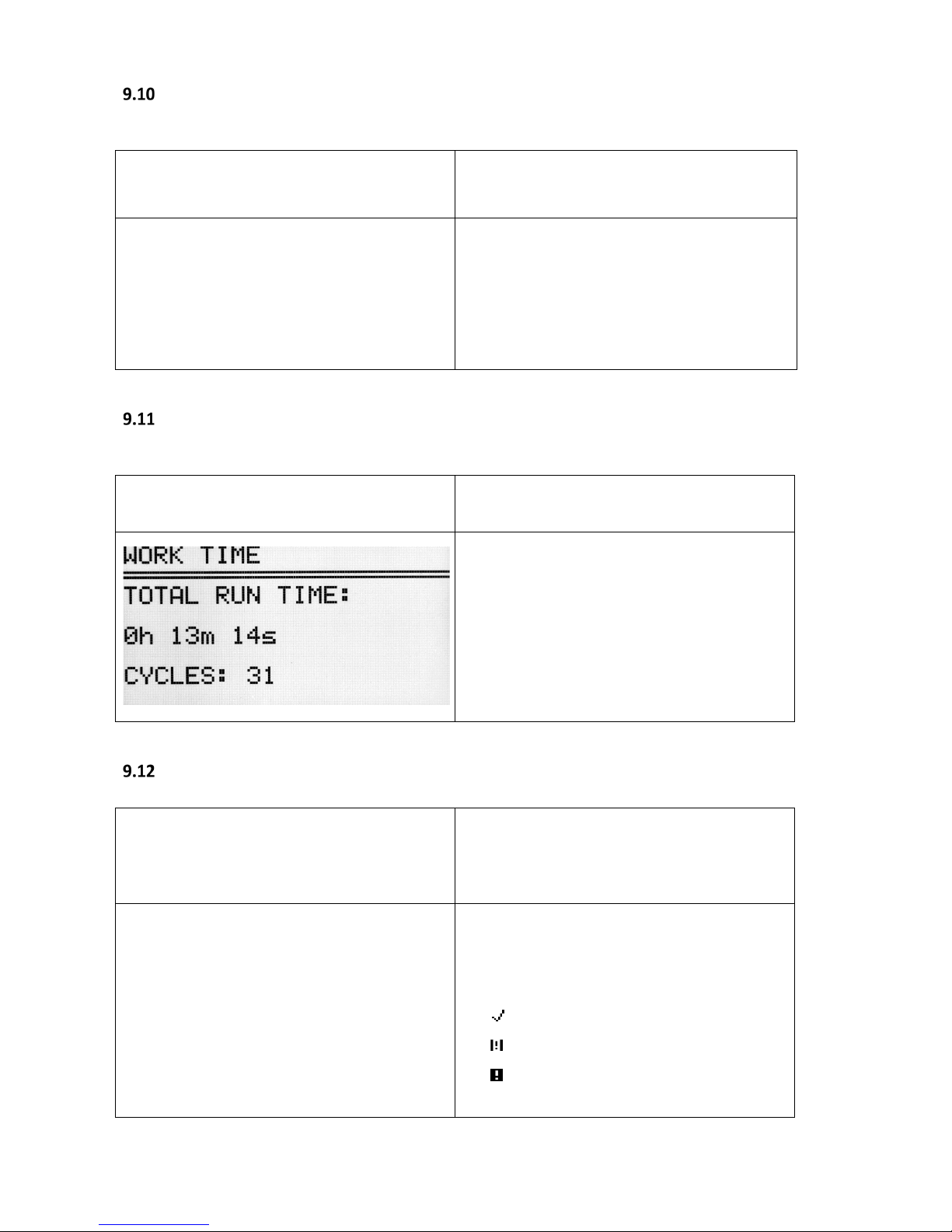
Work time
Total working time of centrifuge and quantity of
working cycles.
MENU / WORK TIME
In the WORK TIME menu,
the following
information is displayed:
total working (centrifugation) time
working cycles counter
Rotor runtime
Information about the time of centrifuging and
of the quantity of the working cycles
of each
rotor. The table also contains icons confirming
successful validation of the centrifuging.
MENU / ROTOR RUNTIME
The list can be scrolled using ▲▼ keys.
To exit press BACK key.
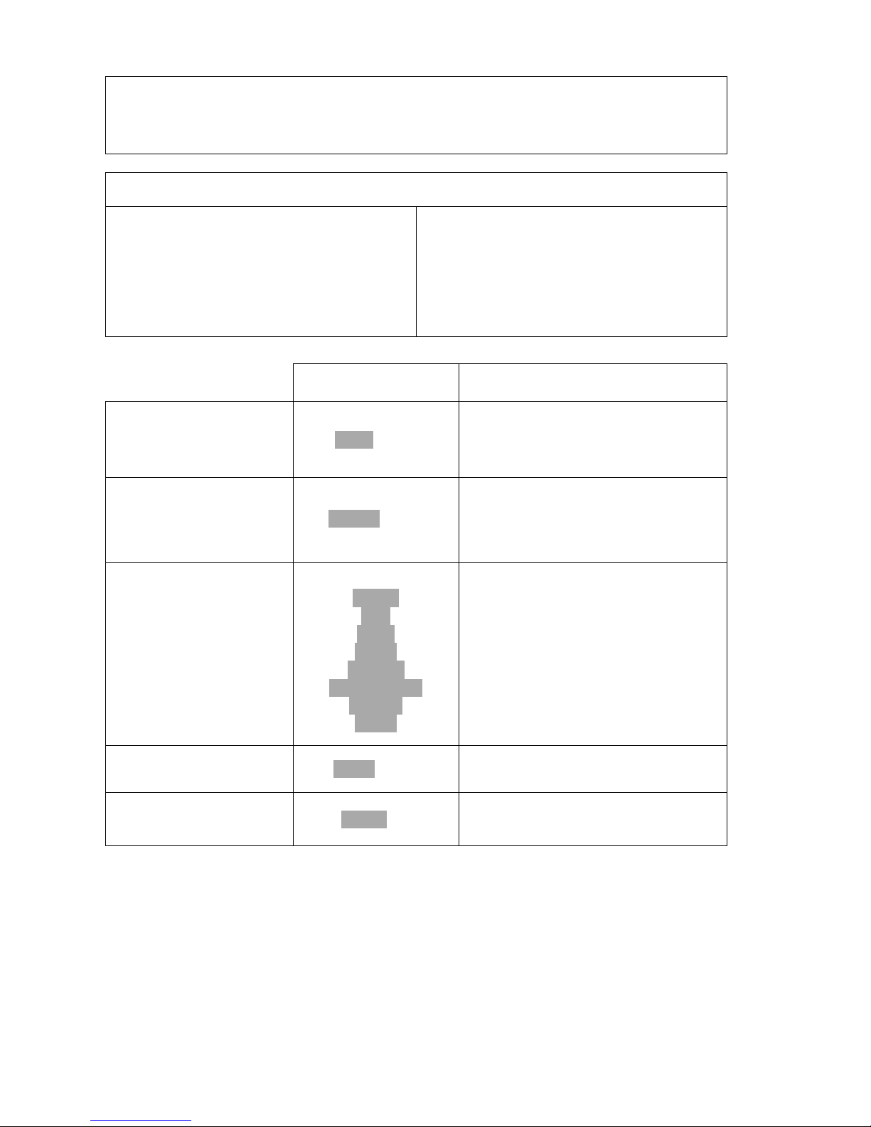
Symbols:
– more than 100 cycles left
– less than 100 cycles left
– worn rotor
Page 53
53
Contact us
Information about the type of the centrifuge,
firmware version, and contact details.
MENU / CONTACT US
The list can be scrolled using ▲▼ keys.
To exit press BACK key.
Diagnostics
Information about errors during the operation of
the centrifuge (for service).
MENU / DIAGNOSTICS
Intended for service purposes!
The list can be scrolled using ▲▼ keys.
To exit press BACK key.
Factory settings
Restoring factory setings. MENU/ FACTORY SETTINGS
All settings of user programs will be deleted.
Via ◄► keys choose YES or NO.
Confirm by pressing SET.
Page 54

54
10 Maintenance
Cleaning of the centrifuge
Pull the mains plug before cleaning.
Before any cleaning or decontamination process other than that is
recommended by the manufacturer, the user should ask the manufacturer
if the event the planned process should damage the device
For cleaning, water with soap or other water soluble mild detergent shall be
used.
Avoid corrosive and aggressive substances. It is prohibited to use alkaline
solutions, inflammable solvents or agents containing abrasive particles.
Do not lubricate the centrifuge motor shaft.
If unused, the centrifuge should have its cover left open.
Once a week
Using a wiping cloth, remove any condensate or residues of the products
from the rotor chamber.
Once a month
Check the rotor clamping thread. In case of damage, replace it.
Check the centrifuging chamber for any damage. In case of damage, it can
not be longer be used. Notify authorised service workshop.
Maintenance of centrifuge elements
The rotor pins should always be lubricated with petroleum jelly.
In this way, uniform deflection of the buckets and a quiet centrifuge
operation is ensured.
Cleaning of the accessories
In order to ensure safe operation, carry out regular and periodical
maintenance of the accessories.
Rotors, buckets and round carriers have to withstand high stresses
originating from the centrifugal force. Chemical reactions as well as corrosion
(combination of variable pressure and chemical reactions) can cause
destruction of metals. Hard to observe surface cracks increase gradually and
weaken material without visible symptoms.
Wipe rotor’s pins clean and dry with a paper towel after approx. 400 uses, clean
Page 55

55
or/and autoclave and then lubricate socket with the petroleum jelly.
In case of surface damage, crevice or other change, as well as
corrosion, the part (rotor, bucket, etc.) should be immediately
replaced.
Clamping rotor, containers and reducer inserts must be cleaned regularly to
prevent corrosion.
Cleaning of the accessories should be carried out outside of the centrifuge at
least once every week if not after each use. Use a neutral agent of pH value
6÷8 for cleaning the accessories. It is forbidden to use alkaline agent of pH >
8. Parts should then be dried using soft fabric or in the chamber drier at ca.
50°C.
Angle rotor should be placed on a fabric with holes facing down, for effective
drying.
Do not use bleach on plastic parts of the rotor.
If maintained this way, the useful service life of the device is substantially
increased and susceptibility to corrosion is diminished. Accurate
maintenance increases the service life and protects against premature rotor
failures.
Do not use bleach on plastic parts of the rotor.
According to laboratory standards, minimise the immersion time in each
solution.
Parts made of aluminium are especially prone to corrosion.
Corrosion and damages resulting from insufficient maintenance cannot be
subject of claims lodged against the manufacturer.
The unused rotor should have the lid removed.
HS accessories maintenance.
Check the general condition of seals.
Make sure that rubber O-rings are lightly coated with silicone grease. Use
high vacuum grease, e.g. type „C” by LUBRINA.
The rotor pins should be always lubricated with petroleum jelly.
Page 56

56
Sterilization
Plastics - legend to abbreviations
PS
polystyrene
ECTFE
ethylene/chlorotrifluoroethylene
SAN
styrene-acrylonitrile
ETFE
ethylene/tetrafluoroethylene
PMMA
polymethyl methacrylate
PTFE
polytetrafluoroethylene
PC
polycarbonate
FEP
tetrafluoroethylene/perfluoropropylene
PVC
polyvinyl chloride
PFA
tetrafluoroethylene/perfluoroalkylvinylether
POM
acetal polyoxymethylenel
FKM
fluorcarbon rubber
PE-LD
low density polyethylene
EPDM
ethylene propylene diene
PE-HD
high density polyethylene
NR
natural rubber
PP
polypropylene
SI
silicon rubber
PMP
polymethylpentene
One can use all standard disinfectants. Centrifuges and devices are made of different materials, one should
consider their variety.
radiation β
radiation γ
25 kGy
C2H4O
(ethylene oxide)
formalin,
ethanol
PS ● ○ ● SAN ○ ●
●
PMMA ● ○ ● PC ● ● ● PVC ○ ●
●
POM ● ●
●
PE-LD ● ●
●
PE-HD ● ● ● PP ● ● ● PMP ● ●
●
ECTFE, ETFE
○ ● ●
PTFE ○ ●
●
FEP, PFA
○ ● ●
FKM ○ ●
●
EPDM ○ ● ● NR ○ ● ● SI ○ ●
●
●
may be used
○
cannot be used
In the centrifuge, disinfectants and cleaning agents generally used in medical care should be used
(e.g. Aerodesina-2000, Lysoformin 3000, Melseptol, Melsept SF, Sanepidex, Cutasept F).
Page 57

57
10.3.1 Autoclaving
Rotors, buckets and round carriers can be sterilised in autoclaves with temperature up to 121°C for
at least 20 mins (215 kPa), unless otherwise specified in the
OPTIONAL ACCESSORY.
During sterilisation (autoclaved) by means of steam, temperature resistance of individual materials
should be considered.
Distortion of the accessories (carriers or lids made of plastic) may occur during autoclaving.
Do not autoclave disposable materials (e.g. tubes, cyto-container).
The life of the accessories depends on the frequency of autoclaving and use.
Autoclaving reduce lifespan of plastic and mechanical components. PC tubes can become useless.
Pressure in closed containers can cause plastic distortion or explosion.
Prior to autoclaving the rotors and accessories, wash and rinse thoroughly with distilled water.
Never exceed the permissible autoclaving temperature and time.
If you want to keep the hermetic seals, replace the sealing rings after each autoclave.
Chemical resistance of plastics
autoclaving
121 °C,
20 min
autoclaving
121 °C,
20 min
PS ○ PMP
●
SAN ○
ECTFE,
ETFE
●
PMMA
○
PTFE
●
PC
●
FEP, PFA
●
PVC
○
1)
FKM
●
POM
●
EPDM
●
PE-LD ○ NR
○
PE-HD ○ SI ● PP
●
●
may be used
○
cannot be used
1)
Except PVC hoses
which are resistant to steam sterilisation at 121°C.
Page 58
58
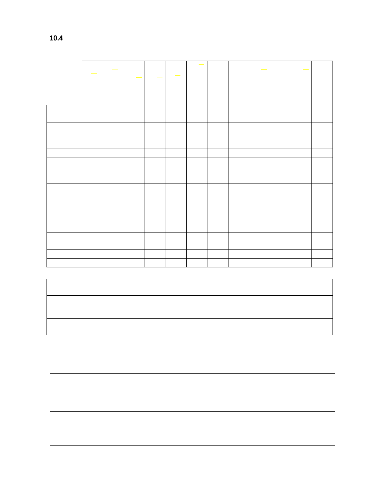
Chemical resistance
Chemical resistance of plastics
aldehydes
cyclic alcohols
esters
ether
ketones
strong or
concentrated acids
weak or diluted
acids
oxidizing
substances
cyclic
hydrocarbons
ahs
haloid
hydrocarbons
alkalis
PS
○
● ○ ○ ○
○/● ○/●
○ ○ ○ ○ ●
SAN
○
●
○
○ ○ ○
○/●
○ ○ ○ ○ ●
PMMA
○/●
●
○
○ ○ ○
○/●
○
○/●
○ ○ ○
PC
○/●
●
○
○ ○ ○
○/●
○
○/●
○ ○ ○
PVC
○
●
○
○ ○ ● ● ○ ● ○ ○ ●
POM
○/●
●
○
● ● ○ ○ ○ ● ● ● ●
PE-LD
●
●
●
○/●
● ● ○ ● ● ● ●
PE-HD
●
●
○/●
○/● ○/●
● ● ○ ●
○/●
○/●
●
PP
●
●
○/●
○/● ○/●
● ● ○ ●
○/●
○/●
●
PMP
○/●
●
○/●
○/●
● ● ○
○/●
○ ○ ●
ECTFE
ETFE
●
●
● ● ○ ● ● ● ● ● ● ●
PTFE
FEP
PFA
●
●
● ● ● ● ● ● ● ● ● ●
FKM
●
○
○
○ ○ ○ ●
○/●
○/●
○/●
○/●
○/●
EPDM
●
●
○/●
○
○/●
● ●
○/●
○ ○ ○ ●
NR
○/●
●
○/●
○ ○ ○
○/●
○ ○ ○ ○ ●
SI
○/●
●
○/●
○ ○ ○
○/●
○ ○ ○ ○
○/●
● very good
Permanent use of the substance over 30 days does not cause damage. The material is able
to be resistant for years
○/● good to limited
Continuous use of the substance causes insignificant and partly reversible damage through
the period of 7-30 days (e.g. puffing up, softening, reduced mechanical durability,
discolouring).
○ limited
The material should not have continuous contact with the substance. Immediate damage is
possible (e.g. the loss of mechanical durability, distortion, discolouring, bursting, dissolving).
Rubber inserts should be thoroughly cleaned or replaced when needed. Centrifuges and accessories are
made of different materials.
Do not use bleach on plastic parts of the rotor.
DANGER!
MSE accessories are not biotight. For centrifuging infectious materials, it is necessary to use
hermetically closed tubes meeting demands of biotightness, in order to prevent germs
migration into the centrifuge and beyond it.
User is responsible for proper disinfections of the centrifuge in the event of dangerous
material spillage inside or outside of the centrifuge. During the above mentioned works,
you must wear safety gloves.
Page 59
59
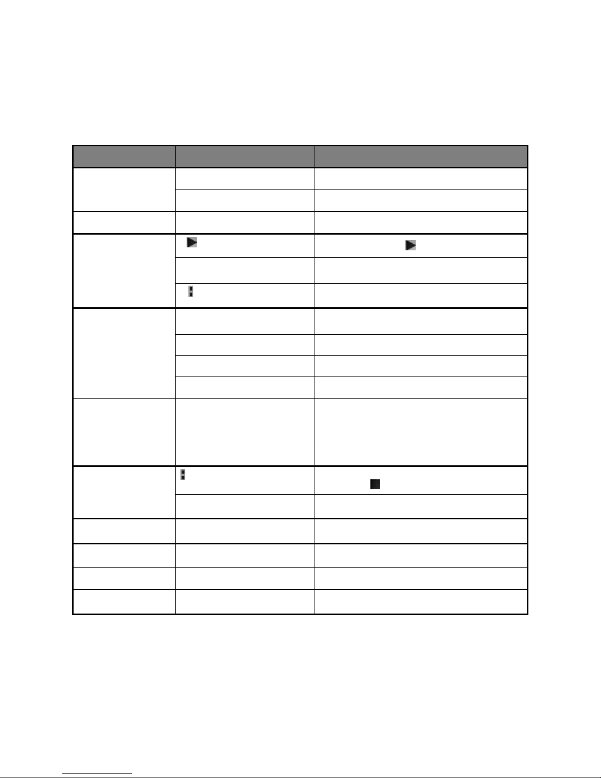
11 Troubleshooting
The majority of faults can be removed by switching the centrifuge OFF and ON. After switching the
centrifuge ON, parameters of the last programme will be displayed and sound signals comprising four
successive tones will be generated. In case of short-duration power failure, the centrifuge terminates the
cycle and displays PROGRAM ERROR code.
problem
question
Remedy
Centrifuge does not start
Is supply cable plugged into mains? Plug supply cable correctly.
Is master switch ON? Switch ON power supply.
Motor error is displayed Call service.
Centrifuge does not start
(indications are proof for
cycle in progress and motor
does not start)
Is symbol displayed?
Wait till rotor stops and the symbol goes off.
Is symbol displayed?
Close cover. symbol must switch off.
Is symbol flashing?
Centrifugation cycle in progress, press STOP key or wait till cycle
ends.
Centrifuge does not
accelerate
(unbalance error)
Unequal rotor load. Centrifuge load needs to be balanced.
Inclined centrifuge. Centrifuge needs to be levelled.
Faulty drive (mechanical damage). Call service.
Was centrifuge moved during operation? Switch ON the centrifuge again after opening and closing the cover.
(motor error)
After stopping, error rotor message is
displayed
Check if rotor number in programme is consistent with the number
of the rotor installed in the centrifuge.
Check rotor status (if there are coding magnets inserted)
Centrifuge does not recognise the rotor
and does not stop.
Switch the centrifuge OFF, then ON and check loaded programme is
correct
It is not possible to open the
cover
symbol on the display is flashing, after
pressing COVER key single tone is audible
Rotor is still rotating. Wait for complete stop of the rotor and
displaying of the symbol.
The sensor is connected correctly, and the
error is still displayed.
Call service.
Mains failure during run
The message about power failure will
display.
Wait for complete stop of the rotor, clear the error by pressing the
SET key.
Temperature sensor error
The overheating message will be
displayed.
Switch the centrifuge OFF, then ON.
Call service.
Error re overheating (50°C) in
the chamber
The overheating message will be
displayed.
Call service.
Page 60

60
Emergency cover release
EMERGENCY COVER RELEASE
You can manually open the lid (eg. in case of power failure). To do this, insert the key into
the emergency opening of the cover (Cat. No. 17162) into the hole on the right side of the
chassis and then push it until you release the lock of the lock and open the cover.
CAUTION! The cover can be opened in emergency only when the rotor is at rest. You should
check this by looking inside the centrifuge using the viewfinder provided in the lid.
Page 61

61
12 Guarantee
Manufacturer grants the Buyer the guarantee with conditions specified in the Guarantee Certificate. Buyer
forfeits the right to guarantee repair when using the device inconsistently with the User manual provisions,
when damage results from the User’s fault.
Repairs should be carried out in authorised MSE service workshops.
The centrifuge shall be sent for repair after decontamination
.
Page 62

62
13 Disposal
When disposing of the device, statutory rules must be observed.
Pursuant to guideline 2002/96/EC (WEEE), all devices supplied after August
13, 2005, may not be disposed as part of domestic waste.
The device belongs to the 8
th
group (medical devices) and is categorised
in business to business field.
The icon of the crossed-out rubbish bin shows that the device cannot be
disposed as part of domestic waste. The waste disposal guidelines of the
individual EC countries might vary. If necessary, contact your supplier.
Page 63
63
14 Manufacturer’s info
MSE Centrifuges LIMITED
+44
1435 517 000
sales department
Mytogen House
1435 517 005
service
11 Browning Road
1825 700 471
fax
Heathfield
TN21 8DB
http://
www.mseuk.com
UNITED KINGDOM
e-mail:
DISTRIBUTOR:
Page 64

64
15 ANNEXES
Page 65
11 Browning Road, Heatheld, East Sussex. UK. TN21 8DB
Sales: +44 (0) 1435 517 000
Service : +44 (0) 1435 517 005
www.msecentrifuges.com
Distributor
MICROCENTAUR R
Refrigerated Micro Centrifuge
Maximum speed 18000 rpm
Maximum RCF 24270 xg
Maximum Volume 24 x 2/1.5ml
HAWK
Compact Centrifuge
Ambient and Refrigerated
Swing Out / Fixed Angle / Microplate
Maximum speed 18000 rpm
Maximum RCF 24270 xg
Maximum Volume 4 x 100ml
Meet the rest of the family
Brand new generaon of centrifuges
 Loading...