

M-S Cash Drawer 7193 User Manual

7193 Thermal Receipt Printer
Owner's Guide
OnLine
PaperOut
PaperFeed
7193-D100-V001

It is the policy of Axiohm IPB to improve products as new technology, components,
software, and firmware become available. Axiohm IPB, therefore, reserves the right to
change specifications without prior notice.
All features, functions, and operations described herein may not be marketed by Axiohm
IPB in all parts of the world. In some instances, photographs are of equipment prototypes.
Therefore, before using this document, consult your Axiohm IPB representative or office
for information that is applicable and current.
Copyright © 1993, 1996 by Axiohm IPB
Ithaca, New York USA
All Rights Reserved
Printed in USA
Confidential, Unpublished
Property of Axiohm IPB
Axiohm IPB is the name and mark of Dardell Technologies. NCR is the name and mark of
AT&T Global Information Solutions. AT&T Global Information Solutions is the name and
mark of AT&T. Epson is the name and mark of Seiko Epson Corporation.
Federal Communications Commission (FCC)
Radio Frequency Interference Statement
Warning
This equipment generates, uses, and can radiate radio frequency energy and if not
installed and used in accordance with the instructions manual, may cause interference to
radio communications. It has been tested and found to comply with the limits for a Class
A computing device pursuant to Subpart J of Part 15 of FCC Rules, which are designed to
provide reasonable protection against such interference when operated in a commercial
environment. Operation of this equipment in a residential area is likely to cause
interference in which case the user at his own expense will be required to take whatever
measures may be required to correct the interference.
Information to User
This equipment must be installed and used in strict accordance with the manufacturer's
instructions. However, there is no guarantee that interference to radio communications
will not occur in a particular commercial installation. If this equipment does cause
interference, which can be determined by turning the equipment off and on, the user is
encouraged to contact Axiohm immediately.
The Axiohm IPB company is not responsible for any radio or television interference
caused by unauthorized modification of this equipment or the substitution or attachment
of connecting cables and equipment other than those specified by Axiohm IPB. The
correction of interferences caused by such unauthorized modification, substitution or
attachment will be the responsibility of the user.

7193 Owner’s Guide Quick Reference
Quick Reference
This Quick Reference will direct you to key areas of the Owner's Guide. For a
complete listing of topics, see the Contents or Index.
Ordering Paper and Supplies page 4
Information on where and how to obtain paper and optional items.
Setting Up the Printer page 9
Basic requirements for unpacking and installing the printer.
Loading and Changing Paper page 19
A brief discussion of the simple paper loading procedure.
Testing the Printer page 23
Procedures for running a test to check the print quality of the printer.
Solving Problems page 29
What to do if a problem occurs.
Diagnostics page 33
A technical discussion of the three levels of diagnostics available.
Communication Interfaces page 45
Specifications for the RS-232 and Parallel communication interfaces.
Commands page 63
Lists and descriptions of the programming commands.
Specifications page 101
Technical specifications for the printer.
May 1996 i

Quick Reference 7193 Owner’s Guide
How to Use This Book
Use this book as an installation guide for setting up and preparing the printer to
run, as a training guide for teaching users how to operate the printer, or as a
reference for programming the host system to communicate with the printer. In
addition, information is also provided about the character sets and graphics that
are available. The book is divided into chapters that relate to each of these areas.
See the Quick Reference, Contents, or Index for detailed listings.
Who Should Use this Book?
This book is intended as a general guide for operators and supervisors who need
to know how to set up and use the printer. It is also intended as a technical guide
for programmers and system integrators who need to know the technical
information about the printer's communication and the programming commands
used by the host system to control the functions of the printer.
How to Obtain More Information
For more information about the 7193 printer and to order the following
documentation, please contact your Axiohm supplier:
• 7193 Thermal Receipt Printer: Service Guide (7193-D200-V001)
Service and disassembly procedures (you must be a trained service
representative to service the printer)
• Parts Information Manual (7193-D300-V001)
May 1996ii

7193 Owner’s Guide Contents
.......
.........
Contents
About the 7193 Printer
Setting Up the Printer
1
Models ..................................................................................................................2
Communication Interfaces ...........................................................................2
Options........................................................................................................... 2
Features................................................................................................................. 2
Thermal Printhead...............................................................................................3
Ordering Paper and Supplies.............................................................................. 4
Ordering Thermal Paper...............................................................................4
Ordering the Power Supply and Cables......................................................6
Ordering the Printer Wall-Mount Kit..........................................................6
Ordering Cash Drawers................................................................................6
Cleaning the Printer.............................................................................................7
9
What Is in the Box? ..............................................................................................9
Removing the Packing Material................................................................... 9
Repacking the Printer..................................................................................10
Choosing a Location ..........................................................................................11
Setting Switches .................................................................................................12
Attaching the Feet..............................................................................................14
Connecting Cash Drawer Cables......................................................................15
Connecting Communication and Power Cables..............................................16
RS-232C Models ..........................................................................................16
Parallel Models............................................................................................17
Turning On the Printer......................................................................................18
Loading and Changing Paper ........................................................................... 19
When to Change the Paper.........................................................................19
Removing the Paper Roll............................................................................ 20
Putting In the Paper Roll ............................................................................21
Advancing Paper.........................................................................................22
May 1996 i

Contents 7193 Owner’s Guide
...............
........................
.................
Testing the Printer .............................................................................................23
Mounting the Printer on a Wall........................................................................25
Mounting the Power Supply on a Wall............................................................27
Solving Problems
Diagnostics
Communication
29
Operator Panel Lights........................................................................................29
Correcting Problems..........................................................................................30
Operator-Correctable Conditions..............................................................30
Service-Related Problems...........................................................................30
Contacting a Service Representative .........................................................31
33
Level 0 Diagnostics............................................................................................33
Level 1 Diagnostics............................................................................................34
Setting Data Error and Data Buffer options .............................................35
Setting Printhead Resistance......................................................................36
Setting Default Lines per Inch....................................................................37
Setting Partial Cut Distance .......................................................................38
Ignoring/Using the Carriage Return.........................................................39
Running the Data Scope Mode ..................................................................40
Testing Receipt Printing .............................................................................42
Level 2 Diagnostics............................................................................................43
Level 3 Diagnostics............................................................................................43
45
Communication Overview................................................................................45
Interfaces......................................................................................................45
Sending Commands....................................................................................45
RS-232C Interface...............................................................................................46
XON/XOFF Protocol..................................................................................47
DTR/DSR Protocol.....................................................................................47
RS-232C Technical Specifications...............................................................48
Parallel Interface ................................................................................................52
Parallel Protocol..........................................................................................52
Parallel Technical Specifications................................................................53
May 1996ii

7193 Owner’s Guide Contents
........................
.
Commands
Appendix A: Specifications
57
Command List....................................................................................................57
Printer Function Commands......................................................................58
Print Characteristics Commands...............................................................60
Graphics Commands ..................................................................................61
Printer Status Commands...........................................................................61
Real Time Commands................................................................................. 62
Bar Code Commands..................................................................................62
Command Descriptions.....................................................................................63
Printer Function Commands......................................................................63
Print Characteristics Commands...............................................................73
Graphics Commands ..................................................................................79
Printer Status Commands...........................................................................84
Real Time Commands................................................................................. 87
Bar Code Commands..................................................................................98
101
Features.............................................................................................................101
Reliability.......................................................................................................... 101
Power Requirements........................................................................................102
Environmental Conditions..............................................................................102
Dimensions and Weight ..................................................................................103
Printing Specifications..................................................................................... 103
Print Zones ....................................................................................................... 104
Density of Receipt Print Lines.........................................................................105
Duty Cycle Restrictions (Printing Solid Blocks)............................................105
Appendix B: Print Characteristics 107
Index .................................................................................................................111
May 1996 iii
7193 Owner’s Guide About the 7193 Printer
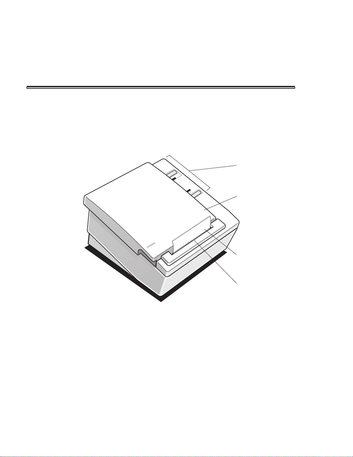
About the 7193 Printer
The 7193 thermal receipt printer is fast (at 600 lines per minute), quiet, and very
reliable. With thermal printing technology, there is no ribbon cassette to change,
and paper loading is extremely simple. The printer is small enough to fit almost
anywhere and is easy to use with the receipt exiting from the top. There is no
journal as it is kept electronically by the host system.
Operator
Panel
OnLine
PaperOut
PaperFeed
Cover
Receipt
Paper
TearOff
Blade/Knife
May 1996 1

About the 7193 Printer 7193 Owner’s Guide
Models
There are several models of the 7193 depending on the communication interface
and the combination of options selected.
Communication Interfaces
• RS-232C
• Parallel
See the “Communication” chapter later in this book for more information.
Options
The following options are available:
• Paper cutter
• Cash drawer drivers: will open a separately purchased cash drawer under
software command
• Wall-mount kit for hanging the printer on a wall (see “Setting Up the Printer”
later in this book)
Features
All models come with the following features:
• Remote power supply with wall-mount kit (see “Setting Up the Printer” later
in this book)
• Drop-in paper loading which does not require using a spindle or threading
the paper through a paper path
• Host-selectable 44 or 56 columns of print on 80 mm wide “fax grade” thermal
paper
• 600 print lines per minute
• Two resident selectable character sets:
• PC Code Page 437 (US)
• PC Code Page 850 (Multilingual)
• 16K RAM available for downloadable character sets and bit-mapped graphics
• 4K buffer
May 19962

7193 Owner’s Guide About the 7193 Printer
• History EEROM
• Speaker
• Resident bar codes
• Code 39
• UPC-A
• UPC-E
• JAN8 (EAN)
• JAN13 (EAN)
• Interleaved 2 of 5
• Codabar
Thermal Printhead
The 7193 uses a thermal printhead which is extremely fast and quiet. Because it
uses heat to print directly on paper, there is no cassette or ribbon to change,
eliminating soiled fingers and paper dust.
The printhead is designed for a very long life, but it may be replaced if needed.
Only a trained service technician may replace the printhead. See “Solving
Problems” later in this book to determine if the printhead needs to be replaced. If
the printhead needs to be replaced, contact your Axiohm authorized service
organization. See “Cleaning the Printer” later in this chapter for cleaning
instructions for the printhead.
May 1996 3

About the 7193 Printer 7193 Owner’s Guide
Ordering Paper and Supplies
Thermal receipt paper and other supplies can be ordered from several
recommended and qualified suppliers.
Ordering Thermal Paper
The 7193 requires “fax grade” thermal paper with the following dimensions:
• Diameter: 80 mm maximum (3.15 in.)
• Length: 83 meters (273 ft.)
• Width: 80 mm ± .5 mm (3.15 ± .008 in.)
The paper must not be attached at the core or the printer will be damaged when
the paper runs out. When the paper runs out, the printer stops printing and turns
on the Paper Out light (red) on the operator panel. There is no indication or
automatic signal when the paper runs low. It is recommended that you use a
paper roll with a colored stripe at the end of the roll to indicate that the paper is
running low.
Recommended Suppliers
The grades of paper listed here will give the best print quality. When more than
one stock or paper grade number is listed, the first number (standard density)
provides better image density. You may order paper directly from AT&T Global
Information Solutions. Contact your Axiohm supplier for ordering paper
manufactured by Kanzaki (paper grades listed on the next page).
AT&T Global Information Solutions Company
Media Products Division
9995 Washington Church Road
Miamisburg, OH 45342
Voice: 1(800)543-8130 (toll free), or local listing of Media Products sales office
Stock numbers: 878559 (standard density), 856966 (light density)
May 19964

7193 Owner’s Guide About the 7193 Printer
Kanzaki Specialty Papers
In U.S. A.
Imaging Products
Voice: 1(413)736-3216, 1(800)628-8386 (toll free)
Fax: 1(413)731-8864
Paper grade: F380 (standard density), F180 (light density)
In Japan:
New OJI Paper Co., Ltd.
Voice: (03)3563-4763
Fax: (03)3563-1136
Paper grade: KF-740-2EX (standard density), KF-740-1EX (light density)
In Germany:
Kanzan Spezialpapiere GMBH
Voice: 011 49 2421 5924 20
Paper grade: KF-60 (standard density), KF-50 (light density)
Other Qualified Suppliers
The following companies manufacture thermal receipt paper which has been
tested with the 7193 and may be used if desired. Contact your Axiohm supplier
for further information.
Appleton Papers, Inc.
Voice: 1(414) 734-9841
Paper grade: T1012
Arjo-Wiggins Thermal Papers, Ltd.
Voice: 44 (0) 522 681212
Fax: 44 (0) 522 690972
Paper grade: S552, S662
Nippon Paper Industry Co., Ltd.
Business Communication Paper Division
Voice: (03)3218-8049
Fax: (03)3216-1397
Paper grade: TP50 KS
May 1996 5

About the 7193 Printer 7193 Owner’s Guide
Ordering the Power Supply and Cables
Contact your Axiohm supplier to order the power supply and cables. The
Axiohm numbers are for reference only. Suppliers may use different numbers.
• Power supply with attached cable (to printer)
and wall-mount kit: 7193-F301
• Separate power supply cord (to outlet)
Order for appropriate power connector
• United States: 7193-F320
• International:7193-F321
• United Kingdom: 7193-F322
• S.E.V.: 7193-F323
• Australia: 7193-F324
• Japan: 7193-F325
• Communication cables
• RS-232C 25-pin (host) to 9-pin:
1420-C001-0030 (3 meters—9.8 ft.)
• RS-232C 9-pin to 9-pin: 1416-C057-0030 (3 meters—9.8 ft.)
• Parallel 25-pin to 25-pin: 1420-C003-0030 (3 meters—9.8 ft.)
Ordering the Printer Wall-Mount Kit
Contact your Axiohm supplier to order the printer wall-mount kit. The Axiohm
number below is for reference only. Other suppliers may use a different number.
Printer wall-mount kit: 7193-K260-V001
Ordering Cash Drawers
The following cash drawers may be used with the 7193 printer:
• AT&T Global Information Solutions
(NCR Cash Drawer): Model 7052-K657
• M-S Cash Drawer Corp.: Model EP-125 K series,
• APG Cash Drawer: Model 237
• Indiana Cash Drawer: Model SLD
EP-127, EP-102
May 19966

7193 Owner’s Guide About the 7193 Printer
Cleaning the Printer
There is no customer maintenance required for the 7193. However, you may
occasionally clean the cabinet as needed to remove dust and finger marks. Use
any household cleaner designed for plastics, but test it first on a small unseen
area. The cabinet materials and finish are durable and are resistant to the
following items:
• Cleaning solutions
• Lubricants
• Fuels
• Cooking oils
• Ultraviolet light
If the receipt paper bucket is dirty, wipe it with a clean, damp cloth.
Caution: Do not spray or try to clean the thermal printhead or the inside of the
printer with any kind of cleaner as this may damage the thermal printhead and
the electronics.
If the printhead appears dirty, wipe it with cotton swabs and rubbing alcohol. If
spotty or light printing problems persist after cleaning the thermal printhead, see
“Solving Problems” later in this book.
Note: The thermal printhead does not normally require cleaning if the
recommended paper grades are used. If non-recommended paper has been used
for an extended period of time, cleaning the printhead with cotton swabs and
rubbing alcohol will not be of much benefit. See “Recommended Suppliers”
earlier in this chapter for the recommended paper grades.
May 1996 7

7193 Owner’s Guide Setting Up the Printer
Setting Up the Printer
What Is in the Box?
The following items are packed in the shipping box:
• Printer enclosed in a plastic bag and foam pack
• Thermal paper roll, wrapped with a foam strip (inside printer)
• Test printout protecting the printhead (inside printer)
• 7193 Setup and User's Guide
• Rubber feet and hook and loop fasteners (fasteners used to anchor printer)
• Power supply with attached cable (to printer) and related items
• Power cord (from power supply to outlet)
• Wall-mount holder for the power supply with screws and wall anchors
• Tie-wrap for cable
These items may be ordered as options and will be shipped separately:
• Wall-mount kit for the printer
• Communication cable (from host system to printer)
• Cash drawer with cables (see “Ordering Cash Drawers” on page 6)
Removing the Packing Material
1. Remove the printer from the foam pack and open the receipt cover by pulling
up on the front left corner.
2. Remove the paper roll and test printout from inside the printer.
3. Remove the foam strip from around the paper roll.
4. Save all packing materials for future storing, moving, or shipping the printer.
May 1996

Setting Up the Printer 7193 Owner’s Guide
Repacking the Printer
1. Protect the printhead by placing a piece of receipt paper between the receipt
cover and the printhead.
2. Place the printer in the plastic bag and foam pack.
3. Place the packed printer in the box and secure the box with packing tape.
4. If you are sending the printer in for repair, call Axiohm IPB for a Return
Authorization Number at (607)274-2402.
Be prepared to answer questions concerning shipping and billing.
5. After you have received a Return Authorization Number, send the printer to
the following address:
Axiohm IPB
950 Danby Road
Ithaca, NY 14850
U.S.A.
May 199610

7193 Owner’s Guide Setting Up the Printer
Choosing a Location
The 7193 is compact and requires little counter space. It may even be mounted on
a wall if space is at a premium. See “Mounting the Printer on a Wall” later in this
chapter. The power supply may also be mounted on a wall or under a table. See
“Mounting the Power Supply on a Wall” later in this chapter. Be sure to plan for
the length of the communication and power cables when choosing a location.
Make sure there is enough room to open the receipt cover and change the paper.
The following illustration shows the actual dimensions of the printer, but leave
several inches around the printer for connecting and accessing the cables.
225mm
(8.85in.)
May 1996
119mm
(4.69in.)
165 mm
(6.50 in.)
187mm
(7.35in.)

Setting Up the Printer 7193 Owner’s Guide
Setting Switches
A group of switches, called DIP switches, located on the bottom of the 7193 is
used for the following purposes:
• To set variables for several printer functions (see the sections for the various
printer functions in “Level 1 Diagnostics” in the “Diagnostics” chapter)
• To perform diagnostic tests (see the sections for the various diagnostic tests
in “Level 1 Diagnostics” in the “Diagnostics” chapter)
• To set communication parameters for the RS-232C communication interface
(see “RS-232C Switch Settings” in the “Communication” chapter)
• To set the data buffer for the Parallel communication interface (see “Parallel
Switch Settings” in the “Communication” chapter)
Caution: The DIP switches are set at the factory to predetermined settings and
should generally not be changed. If you must change the settings do so carefully
to avoid changing other functions.
Before changing any of the switches, first run the print test to print out the
current switch settings on the receipt. See “Testing the Printer” later in this
chapter for instructions on running the print test and for a sample printout.
Note: Switch #1 is used to toggle between regular communication with the host
system and Level 1 Diagnostics (used for the printer functions and level 1
diagnostic tests) as described below:
• Switch #1 set to OFF: printer is ready to communicate with the host system
and receive data (online mode)
• Switch #1 set to ON: printer is in Level 1 Diagnostics (setup mode)
If you want the printer to communicate with the host system, be sure switch 1 is
OFF. Use a paper clip or other pointed object to set the switch.
For additional information on the setup mode (Level 1 Diagnostics), see the
“Diagnostics” chapter.
Note: Some 7193 models may appear slightly different than what is shown in the
illustration. The procedures are the same for all models unless otherwise noted.
May 199612

7193 Owner’s Guide Setting Up the Printer
May 1996

Setting Up the Printer 7193 Owner’s Guide
Attaching the Feet
Use the hook and loop fasteners to anchor the printer to a flat surface; be sure the
surface is clean and dry. Use the rubber pads if you are mounting the printer on
the wall. See “Mounting the Printer on a Wall” later in this chapter.
Note: Some 7193 models may appear slightly different than what is shown in the
illustration. The procedures are the same for all models unless otherwise noted.
Slots for
Rubber Pads
or Hook & Loop
Fasteners
Bottom of Printer
1. Remove the paper from the adhesive on the back of the pads or loop
fasteners and affix them in the slots on the bottom of the printer.
2. Attach the hook fasteners to the loop fasteners (if used).
This will save you having to apply the hook fasteners separately and trying to
match them to the loop fasteners on the printer.
3. Remove the paper from the adhesive on the back of the hook fasteners and
place the printer firmly on the selected surface.
May 199614

7193 Owner’s Guide Setting Up the Printer
Connecting Cash Drawer Cables
The cash drawer option allows up to two cash drawers to be connected to the
printer in a system with a PC that has no connectors for the cash drawer cables.
The cash drawer cables usually come with the cash drawer.
The cash drawers are operated by software command from the host system
through the printer. For additional information on the printer commands used by
the host system to activate the cash drawers, see “Commands” later in this book.
1. Plug the cash drawer cables into the connectors on the printer.
The connectors are standard phone connectors.
2. If only one cash drawer is used, plug the cable into the connector labeled 1.
Note: Some 7193 models may appear slightly different than what is shown in the
illustration. The procedures are the same for all models unless otherwise noted.
May 1996
Communications
Cable Slot
Back View of Printer
1 2
Cash Drawer
Connectors
Power Supply
Cable Slot

Setting Up the Printer 7193 Owner’s Guide
Connecting Communication and Power Cables
The printer receives power from a power supply and uses one cable for
communication and a separate cable for power.
Caution: Be sure that all power is disconnected before connecting the cables.
1. Turn off the host system or unplug the power supply if it is plugged in.
2. Plug the power supply cable into the printer first, then plug the power cord
into the power supply, then into an outlet.
3. Connect the communication cable to the printer, then to the host system.
RS-232C Models
BottomofPrinter
Power
Supply
Connector
Power
SupplyCable
PowerSupply
CableRoute
9-Pin
Communication
Connector
Communication
Cable
May 199616

7193 Owner’s Guide Setting Up the Printer
Parallel Models
BottomofPrinter
Power
Supply
Connector
PowerSupply
CableRoute
May 1996
Power
SupplyCable
2 1
CashDrawer
Drivers
25Pin Female
Communication
Connector
25-pinParallel
Communication
Cable
Setting Up the Printer 7193 Owner’s Guide
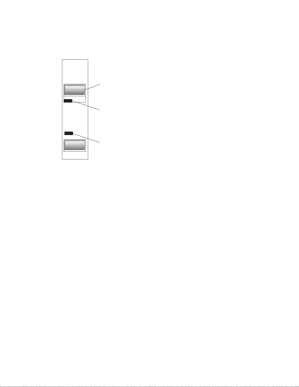
Turning On the Printer
OnLine
Button
OnLine
PaperOut
PaperFeed
Operator Panel (Remote Printer)
OnLine
Light
PaperOut
Light
Note: The printer receives power when the power supply is on even if the printer
is off-line. To remove power from the printer, press the On Line button to take
the printer off-line (On Line light is off), then unplug the power supply power
cord from the outlet.
1. Press the On Line button on the operator panel to put the printer on-line.
The printer goes through a self-test routine to ensure everything is working,
then “beeps.” The On Line light (green) comes on indicating the printer is online. If the On Line light does not come on, or either the On Line light or
Paper Out light flashes, see “Solving Problems” later in this book.
2. Press the On Line button again to take the printer off-line.
When the printer has completed its “startup” cycle it is ready to receive data. If
the Paper Out light flashes, see “Solving Problems” later in this book.
May 199618

7193 Owner’s Guide Setting Up the Printer
Loading and Changing Paper
The 7193 features extremely simple paper loading. See the next two pages for
detailed illustrations.
If you are loading paper for the first time and have already taken the roll out, go
to “Putting In the Paper Roll” later in this chapter. If you have not taken the roll
out, continue with the following instructions. Although the illustrations show a
used roll being removed, the instructions still apply to loading paper for the first
time.
When to Change the Paper
You will need to change the paper when you see a colored stripe on the receipt
paper or when the Paper Out light (red) on the operator panel turns on.
• Paper Low Stripe
When the paper low stripe appears on receipts being printed, change the
paper as soon as possible to avoid running out of paper part way through a
transaction.
• Paper Out light
When the Paper Out light (red) on the operator panel comes on, the paper is
completely out. Do not run a transaction without paper: the data may be lost.
May 1996
Caution: Do not operate the printer or host system if the printer runs out of
paper. The printer will not operate without paper, but it may continue to accept
data from the host system. Because the printer cannot print any transactions, the
data may be lost.

Setting Up the Printer 7193 Owner’s Guide
Removing the Paper Roll
May 199620

7193 Owner’s Guide Setting Up the Printer
Putting In the Paper Roll
Before putting in a new roll, tear off the end of the roll so that the edge is loose.
Placethe roll into the bin with afew inches of
1
paperextending over the cabinet front (ortop,
ifprinter is vertically mounted).
Warning:
bottomof the roll. Otherwise the paper will jam.
Besure the paper unrollsfrom the
OnLine
PaperOut
PaperFeed
Closethe cover.
2
Removethe excess paper by tearing it against
thetear offblade.
3
OnLine
PaperOut
PaperFeed
May 1996

Setting Up the Printer 7193 Owner’s Guide
Advancing Paper
OnLine
PaperOut
Paper
Feed
Button
PaperFeed
OperatorPanel
Note: Some 7193 models may appear slightly different than what is shown in the
illustration. The procedures are the same for all models unless otherwise noted.
1. To advance the receipt paper, press the Paper Feed button on the operator
panel. The cover must be closed.
2. Tear off the excess paper against the tear off blade.
The paper is not cut if it has been manually advanced on printers with the
knife option
May 199622

7193 Owner’s Guide Setting Up the Printer
Testing the Printer
Run this test to check the printer. The test prints the settings for several functions,
prints all variations of the character sets, and partially cuts the paper between
each variation. See the “Diagnostics” chapter for a description of the functions.
A sample printout (RS-232C) is shown later in this section. The printouts for other
models models are similar. The test ends with a partial cut, then begins again.
Several feet of paper can be used to print one pass of the test.
Additional diagnostic tests may be performed by a trained service representative.
For more information, see “Diagnostics” later in this book.
1. Press the On Line Button on the operator panel to take the printer off-line.
The On Line light turns off indicating the printer is off-line.
2. Press and hold the Paper Feed button while pressing the On Line Button.
3. Let go of the Paper Feed button once the printing begins.
The printer begins printing the data and character sets. This can be given to a
service representative if it appears there is a problem.
May 1996
4. To stop the test, press the On Line button.
The On Line light turns off indicating the printer is off-line.
5. To return to the on-line mode, press the On Line button again.
The printer is ready to receive and print data from the host system.

Setting Up the Printer 7193 Owner’s Guide
OnLine
Button
OnLine
PaperOut
Paper
Feed
Button
PaperFeed
Operator Panel
3cx39pi
Sample TestPrint
May 199624
 Loading...