

Page 1

The Select DAC
User Guide
Check our website for the most recent user
guides, rmware, and drivers:
www.msbtechnology.com
Technical support email is:
05.29.18
Page 2

Page 3

Technical specications
Supported Formats
(Input depedent)
Digital Inputs 4x Advanced isolated input module slots
XLR Analog Inputs 100K Ohm Balanced
XLR Analog Outputs 3.57Vrms Maximum (Digital Input)
Volume Control Purely passive constant impedance analog attenuation
Display Custom discrete LED audio clock synchronous display
Controls Isolated RS-232
Chassis Dimensions Width: 17.5 in (444 mm)
Shipping Dimensions Width: 25 in (635 mm)
Included Accessories User Manual
44.1kHz to 3,072kHz PCM up to 32 bits
1xDSD, 2xDSD, 4xDSD, 8xDSD
Supports DSD via DoP on all inputs
12Vrms Maximum
Isolated when not selected
12Vrms Maximum (Analog Input)
75 Ohm Balanced
Galvanically isolated
1dB steps
Adjustable brightness and auto-o feature
IR Remote
Knob + 4 Buttons
Depth: 17.5 in (444 mm)
Height without feet: 3 in (79 mm)
Stack height: 3.625 in (92 mm)
Weight: 25.5 lbs (11 kg)
Depth: 25 in (625 mm)
Height: 10 in (254 mm)
Weight: 55 lbs (24 kg)
MSB Remote
Micro USB Charging Cable
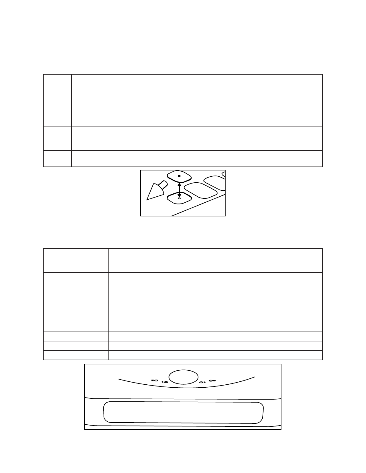
4X Spiked Feet
4x Plastic inserts for feet
Page 4
Setup and Quick Start
The interface is quite simple with few user controls. Input source defaults on to auto switching.
The display will let you know if you have an active input. On power up, the volume is reset to the
programmed startup level. Shipping default is 70. Turn the volume knob up until you hear music.
Power The DAC comes with a high performance powerbase. The powerbase automatically
detects and switches between 240V and 120V. This is not a switching supply that works
at any voltage, but a linear supply with automatic switching of the transformer leads.
The power supply is switched on and o with a button on the front or via the IR remote.
The LED in the front of the Power Base indicates red when OFF and white when ON.
Always allow three to ve hours for the DAC to warm up and reach optimal operating
temperature.
Inputs The DAC comes with the digital input modules of your choice. Connect any digital input
to any active digital audio source. The frequency and bit depth of the incoming signal will
be displayed on the front panel.
Outputs A range of Output Modules are available. Connect the balanced or single-ended analog
outputs to any amplier. The output level is controlled with the knob or remote.
Burn-In
The feedback we receive leads us to recommend at least 100 hours of burn-in on this DAC. Customers
generally report improvement up to one month.
User Interface
Menu Button The square button is single purpose. It will enter the setup mode at the top
Input Selection The right and left arrows switch inputs. The ‘Auto’ mode will be in the list of
Mute The circle button can be used to quickly mute the audio of the DAC.
Volume Knob This knob adjusts the volume between 0 and 106.
Display The display shows the Input, sample rate, bit depth, and volume.
of the menu tree. If in the setup, and it doesn’t matter where, this button
will exit the setup and return to the normal operational mode.
inputs. The right and left arrows switch inputs. If ‘Auto’ is selected, the unit
will automatically switch inputs based on priority (Input slot B is higher than
Input slot A) with the analog input being lowest priority. When a source with
a higher priority becomes active, the unit will automatically switch to the
new higher priority input. Toggling through the inputs manually will defeat
any auto switching. When in the setup menu the arrows move right and left
through the menu structure.
Page 5

About the 4 input module slots
The DAC has four input module slots. They are labeled A through D. There are two classes of input
modules, analog and digital. Analog modules must be placed adjacent to the analog output module.
They can be either be additional analog inputs or a second analog output module. Digital modules can
be placed in any position. Each module is completely self contained. It is recognized by the DAC and
identied on the display. When the module is not in use it is disabled.
Available Digital Input Modules
ProI2S
XLR S/PDIF A single XLR digital input with a word sync output.
Optical/Coaxial S/PDIF A Toslink and Coaxial digital input with a word sync output.
MQA USB A single USB interface for playback via a computer based device. This
Renderer A renderer interface for use on a home network or server. (See
Pro ISL MSB proprietary interface for use with MSB transports. This module
MSB’s proprietary interface for use with MSB transports. This module
provides two inputs.
module provides support for MQA decoding. (See USB manual for
operation and setup details)
Renderer manual for operation and setup details)
provides one input.
Available Preamps
The DAC is available with one of two output modules.
Balanced Preamp Oers one set of balanced analog inputs and outputs. Provides
volume control with our passive constant impedance volume control
technology.
Single-Ended Preamp Oers one set of single-ended analog inputs and outputs. Provides
volume control with our passive constant impedance volume control
technology.
Additional Analog Inputs and Outputs
In addition to the primary output module, additional analog inputs and a secondary analog output
can be added.
Isolated Analog Output Provides a second analog output as single-ended or balanced.
Only one analog output module can be added per DAC.
Isolated Sub Analog Output Provides an isolated sub-woofer output as single-ended or balanced.
Only one can be added per DAC.
Additional Analog Input Provides an extra analog input connection as single ended or balanced.
Multiple inputs can be installed.
Page 6
POWER 2
OUTPUT
RIGHTL EFT
SERIAL
XLR PREAMP
RIGHTL EFT
AMP
GROUNDING TERMINALS
INPUT
MSB
CHASSIS
THE SELECT DAC
105-130. 210-260 VAC
SERIAL
THE REFERENCE
POWERBASE
MSB
TECHNOLOGY
12 VOLT
TRIGGER
RCA
DESIGNED
CALIFORNIA
AND
MADE
IN
TOSLINK
RS-232
WORD
SYNC
OUT
POWER 1
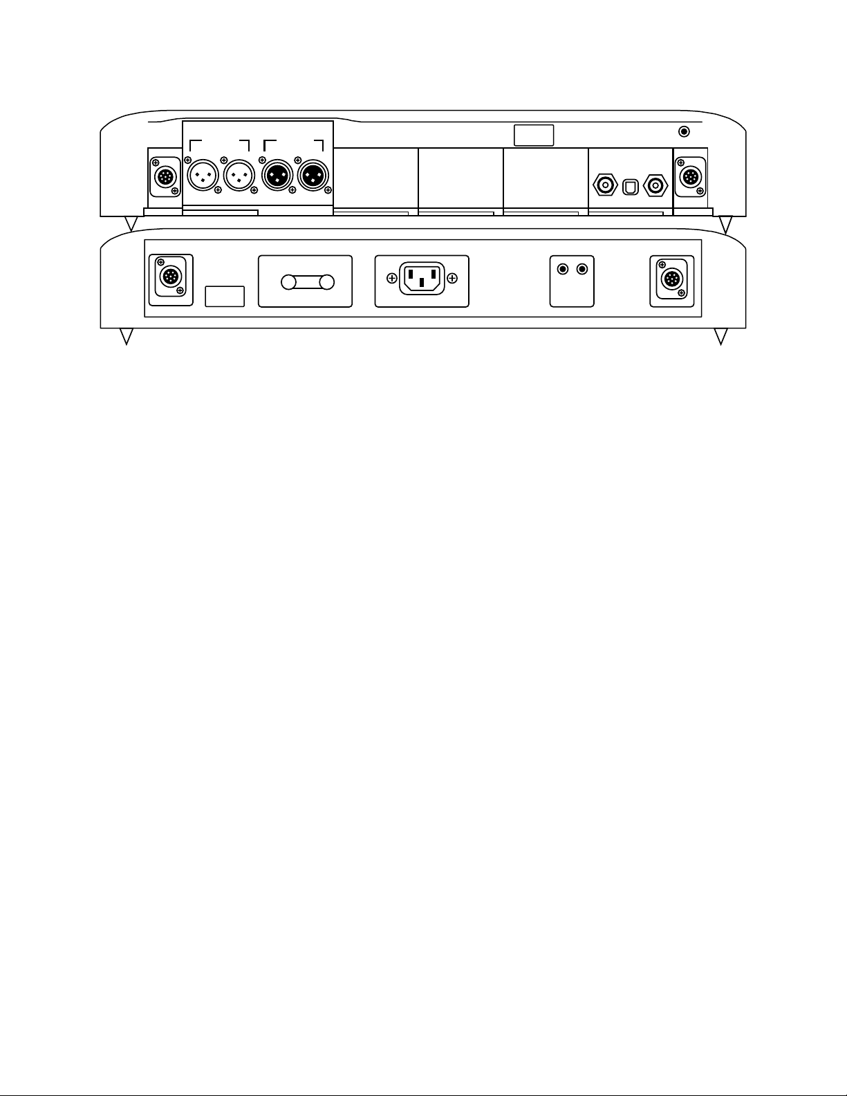
Removing and Installing Modules
Removal and installation of modules is a completely tool free process that is easily performed at
the back of the unit. Under the lower lip of each module is a lever arm. Simply pull the lever out and
away until it is perpendicular with the back of the unit. Then gently, but rmly, pull the module lip
and lever until the module releases and slide it out of the unit.
Analog output and analog input modules must be installed in a special fashion. When installing any
analog output or analog input module, you must remove the preamp output module and attach
the analog output or analog input module into the side connector of the larger preamp module and
then slide the connected pair into the back of the unit as one while making sure both levers are out
and tightened at the same time.
Module Handling
It is important that you refrain from touching the circuit board or rear connector of any input or
output module when removing or installing any input or output module from your DAC. When
handling these modules it is important that you only contact the metal case of the module or the
front edge of the module where the cam arm is located. Improper handling of your modules can
result in static shock and damage to the module or DAC.
Saving Menu and Startup Settings
When changing settings in the menu, use the enter button in the center of your volume wheel on
the remote or the circle on the DAC faceplate to conrm settings in the DAC menu. After you have
made your changes in the DAC menu, use the menu button to exit the DAC menu completely to save
the changes you have made in the DAC menu.
The DAC will not save any of your settings until you exit the menu.
The “Action Buttons” on your remote change certain settings on your DAC without navigating the
DAC menu (Phase Invert and Video Mode). However, these settings reset every time the DAC is reset
or powered o. If you would like these settings to persist through resets or power os, you simply
have to choose the action button setting that you wish to be default and then enter and exit the DAC
menu by double clicking the Menu button on your remote or DAC faceplate.
If at any point the DAC seems to be improperly setup or you want to start fresh with your settings
and functions, there is a “Reset” option near the end of the DAC menu. Simply select this and
conrm “YES” before closing the DAC menu and restarting the unit.
Page 7

Setup Menu Options
Display brightness This can be adjusted from 1 - 10
Display On (Default)
• The display is on continuously.
Auto o
• The display is o but will turn on momentarily when the volume or input
changes.
DSD mode Optimized
• The optimized mode is the DSD decimation done using a special method
developed by MSB.
Native DSD (Default)
• The Native DSD signal is sent unprocessed direct to the Hybrid DAC
modules.
Startup volume This can be adjusted from 0 - 100. This is the default volume the DAC will
power up at. If you choose to use the DAC with a external preamp, we
recommend setting the default volume to 98.
Input switching Manual with smart
• Only allows manual switching between active and previously active inputs.
The ‘Auto’ mode is not available.
Auto with smart (Default)
• Allows manual and auto switching between active and previously active
inputs.
Auto with all inputs
• Allows manual and auto switching between all installed inputs.
Restore DAC settings Conrm
• This restores the DAC to default settings.
Analog Input O (Default)
• Disables the analog input.
On-Volume Controlled
• Enables the analog input and uses the volume control.
On-Volume Bypass
• Enables the analog input and bypasses the volume control.
About screen This screen displays the serial number, year of manufacture, and
distributor name of the DAC.
DAC Software Rev This screen displays the current revision # of rmware installed in the DAC.
Input A Lists the installed input module in slot A.
Input B Lists the installed input module in slot B.
Input C Lists the installed input module in slot C.
Input D Lists the installed input module in slot D.
Output Module
Screen
Displays the current output module installed and the output impedance.
Page 8
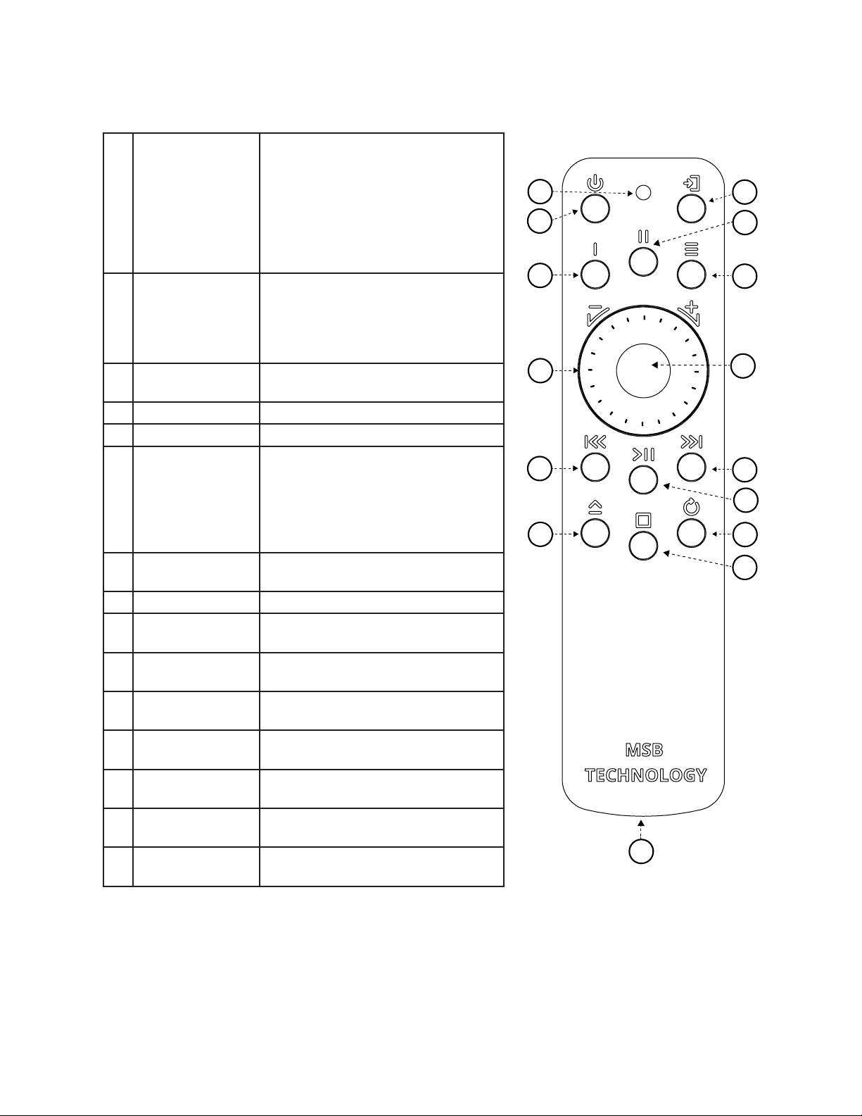
The MSB Remote
1 Indicator LED While in use:
White - Command Sent
Red and White - Command Sent
and Low Battery
Red Flashing - Needs Charging
While charging:
Red - Charging
White - Fully Charged
1 Power Powerbase on and o. When the
powerbase is linked to an amplier
or MSB product, this button will
turn o the entire system
(See powerbase manual for details)
3 Input Toggles directly through DAC
inputs
4 Action 1 Toggles phase invert
5 Action 2 Toggles video mode
6 DAC Menu Enter DAC menu
While in menu:
Up - Volume Up
Down - Volume Down
Enter - Mute
Return - DAC Menu
7 Volume The center scroll wheel controls
DAC volume
8 Mute DAC mute
9 Track Backward Skip/scan backward
(MSB Tranport Only)
10 Play/Pause Play and pause
(MSB Tranport Only)
11 Track Forward Skip/scan forward
(MSB Tranport Only)
12 Eject Eject media disc
(MSB Tranport Only)
13 Stop Stop media
(MSB Tranport Only)
14 Track Repeat Track or album repeat
(MSB Tranport Only)
15 Charging Port Micro-USB to charge the remote
battery
1
2
4
7
9
12
3
5
6
8
11
10
14
13
15
Page 9

The Heart of the System - Preamp and DAC
This product is a unique combination of a very high performance DAC and the ultimate passive preamp.
For the best possible sound in your system, it should be connected directly to your audio ampliers.
Our preamp philosophy is based on the belief that from the moment analog audio is created, every
transition that is made degrades the sound quality. This is why we oer a passive preamp within the
DAC, to achieve the simplest, shortest possible signal path, with the least possible degradation of the
true music. The DAC’s modular design is very exible with the option for one or more analog inputs,
and many digital inputs. It is designed to be the last component in your system before the ampliers
and replaces the need for a traditional preamp. The analog input can be enabled in the menu and
can be set to volume control the analog input or bypass the analog input if you want to use another
volume control for your analog source.
Loading new rmware
Always be certain that you are updated with the current rmware by checking our website. The DACs’
rmware is always updated using a .WAV le. If you experience issues with playback of the update le,
be sure to check for bit-perfect playback in your system.
All rmware updates can be found at:
www.msbtechnology.com/Support
Bit-Perfect Source Testing
The following les can be downloaded from the MSB website to verify bit-perfect playback on any
transport:
16 bit x 44.1 kHz sample rate le (CD standard). 24 bit x 44.1 kHz sample rate le.
16 bit x 48 kHz sample rate le. 24 bit x 48 kHz sample rate le.
16 bit x 88.2 kHz sample rate le. 24 bit x 88.2 kHz sample rate le.
16 bit x 96 kHz sample rate le. 24 bit x 96 kHz sample rate le.
16 bit x 176.4 kHz sample rate le. 24 bit x 176.4 kHz sample rate le.
16 bit x 192 kHz sample rate le. 24 bit x 192 kHz sample rate le.
They are .WAV test les that when played, will be identied by the DAC and checked, and will be
reported on the display if they are bit-perfect. If there is a problem with the test, it will play but the
display will not indicate any change. Be sure upsampling is turned o in any transport as this prevents
a le from remaining bit-perfect. This system will allow you to easily test your source, especially
computer sources, to see if all your settings are correct. There are les at all sample rates for both 16
bit and 24 bit operation.
Page 10

Select Dual and Mono Powerbases
The powerbase contains isolation technology. The powerbase detects the input voltage and switches
to 120 volt or 240 volt operation. It is also available in a xed 100 volt conguration. All powerbases
have over-voltage protection.
Two fuses are provided:
- 5A 250V SLO BLO - 5 mm x 20 mm miniature fuse (This is the main fuse).
- 100mA 250V SLO BLO - 5 mm x 20 mm miniature fuse (This is for the standby supply only).
Technical Specications
AC Voltage 120/240V (Auto switching)
Optional 100V xed conguration
Power Consumption 100 Watts with fully congured Select DAC
Less than 2W standby
Chassis Dimensions Width: 17.5 in (444 mm)
Depth: 17.5 in (444 mm)
Height without feet: 3 in (79 mm)
Stack height: 3.625 in (92 mm)
Weight: 45.8 lbs (20 kg)
Shipping Dimensions Width: 25 in (635 mm)
Depth: 25 in (625 mm)
Height: 10 in (254 mm)
Weight: 65 lbs (29 kg)
Included Accessories 2X Power Cables
Ground Cable
IEC Power Cord
4X Spiked Feet
Powerbase Controls
There is one button on the front of the powerbase as well as two control features just under the
front of the powerbase on the bottom.
Front control White - Power on.
Red - Power o.
Amber - Linked mode, 12 volt trigger controlled.
Flashing Amber - Over-voltage protection.
‘Display’ wheel This is a rolling wheel to control the brightness of the power indication light
Switch Normal - This sets the powerbase as the 12 volt trigger master.
Linked - This sets the powerbase as the 12 volt trigger slave. The ‘master’ powerbase
will control this unit.
Select Mono Powerbase Setup/Connections
After plugging in the powerbase, connect both mono powerbases with the supplied 3.5mm mini jack
cable by plugging it into the 12 volt remote trigger connections. Be sure to check that the primary
powerbase ‘function switch’ is set to the ‘NORMAL’ position. The secondary powerbase switch set to
‘LINKED’. This allows the primary powerbase to control the secondary one without them having to be
turned on/o seperatley.
Page 11
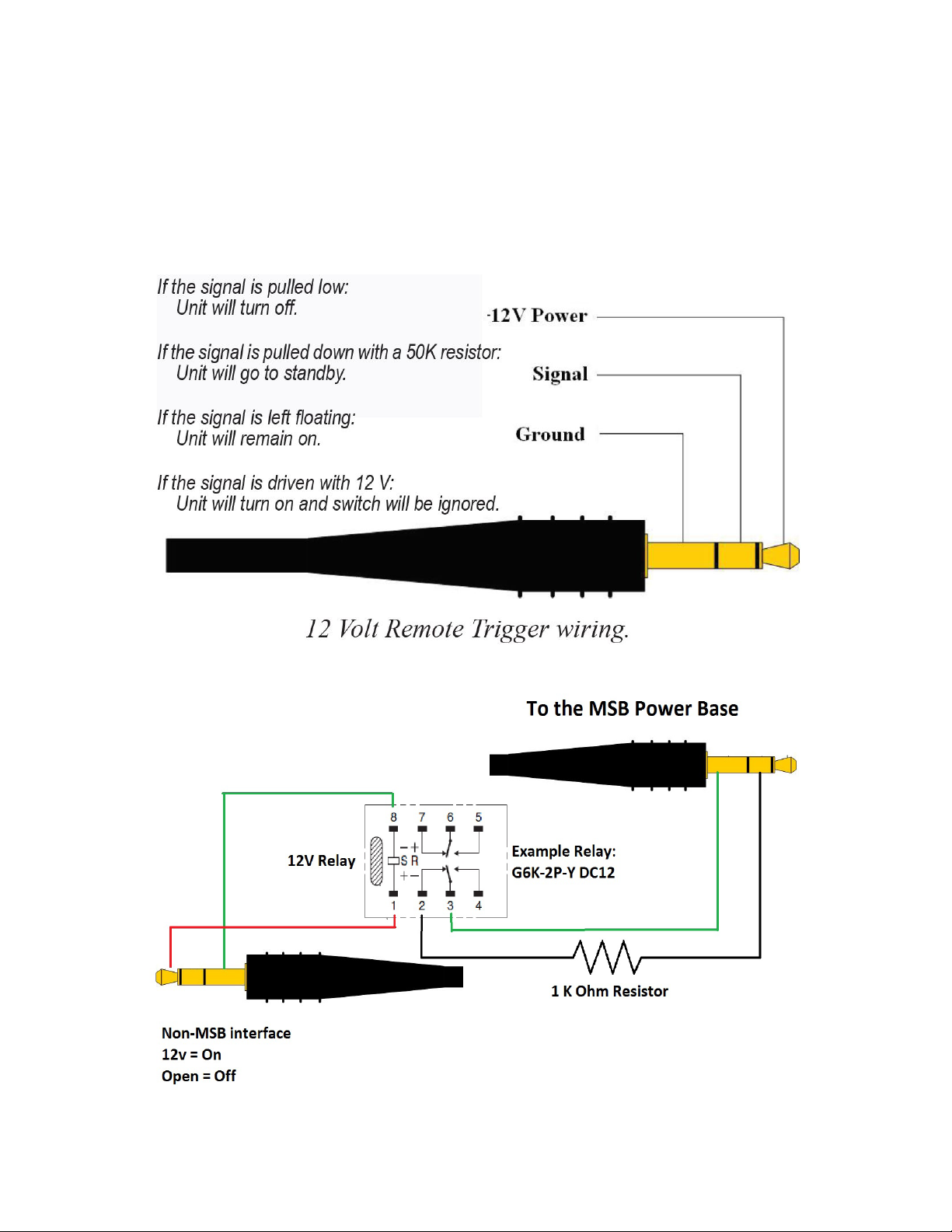
Powerbase - 12 Volt Remote Trigger
This powerbase is equipped with a remote trigger for use with other MSB products. The trigger uses
a 3 pin mini jack. When any MSB product is turned o, the other products connected will also turn
o and vice-versa. This trigger can also be used with other products. Products may use this trigger
dierently, so you may need to rewire a cable or use an interface relay. The connector is wired as
shown. If you connect “signal” to “ground”, all MSB products will turn o. If you connect “signal” to “12
V” or leave it open, all MSB products will turn on.
Page 12
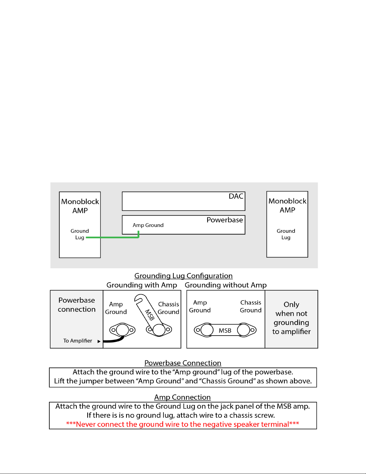
Ground Jumper IN - Basic Operation
The Basic Operation provides isolation only for the DAC. This gets you half the protection available.
For full protection, be sure the jumper is in place between the Chassis Ground and Amplier
Ground. This is the shipping conguration. NEVER OPERATE WITHOUT THE JUMPER OR A GROUND
WIRE ATTACHED.
Ground Jumper OUT - Enhanced Operation
The Enhanced Operation provides isolation for both the DAC and the amplier. This gets you the
full isolation available. With the jumper disconnected, connect the supplied ground wire from the
AMPLIFIER GROUND lug to the chassis of the amplier. Note this connection is dependent on the
amplier so you will have to look for the best place to attach the wire. Generally the easiest place
would be to loosen a screw on the Amplier Chassis and slip the open Spade lug under the screw
head and tighten the screw. The only other place a true ground may be found is on the ground pin
of the power connector to the AMP but this will not be easy to connect too.
Dual Powerbase Grounding Diagram
In this conguration you will simply lift the grounding lug jumper and make a connection from the
“Amp Ground” lug to either ONE of your mono-block ampliers or to your single stereo amplier.
Page 13
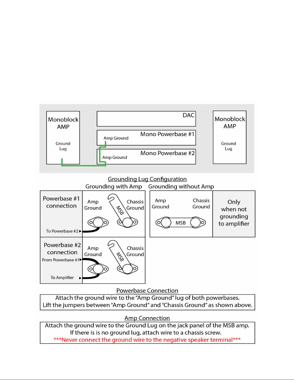
Mono Powerbase Grounding Diagram
In the conguration you will lift the Grounding lug jumper on both powerbases and then make a
connection between the “Amp Ground” lug on both the powerbases and then add an additional
lead from ONE of your powerbases to ONE of your mono-block ampliers or to your single stereo
ampler.
It is important that both grounding lug jumpers are discconected on each of your powerbases to
ensure proper ground isolation.
Page 14

Technical Support
If you are expierencing any issues with your MSB product, please contact your nearest dealer or try
our support page at www.msbtechnology.com/support. Please be sure you have the most current
edition of your products rmware installed. If your issue persists please feel free to contact MSB
directly. Emails are usually responded to in 24 - 48 hours.
Email: [email protected]
MSB Return Procedure (RMA)
If a customer, dealer, or distributor has a problem with an MSB product, they should email tech
support before sending anything back to the factory. MSB will do their best to respond within 24
hours. Should it be clear that a product must be returned, tech support should be informed and all
the following relevant information should be provided:
1. Product in question.
2. Serial number.
3. Detailed fault of the problem.
3. Exact conguration when symptom is observed along with a list with the input used, source material,
system connections, and amplier.
4. Customer name.
5. Customer shipping address.
6. Customer phone number and email.
7. Special return shipping instructions.
MSB will issue an RMA number and create an invoice with all details outlined except the nal price as
the product has not yet been seen. This invoice will be emailed so all the above information can be
checked and veried by the customer.
The product should be returned with the RMA number present on the box. Work can then begin
immediately and the product can be sent back quickly.
Any repair that is dicult and cannot be completed in two weeks will be identied and the customer
will be informed when it is to be expected. Otherwise the majority of repairs should be shipped back
within two weeks if all the required information is present on the invoice.
Link to page:
http://www.msbtechnology.com/faq/msb-product-return-procedure/
Page 15

The Select DAC Limited Warranty
Warranty includes:
• MSB warrantys the unit against defects in materials and workmanship for a period of 10 years
from the date the unit was originally shipped from MSB.
• This warranty covers parts and labor only, it does not cover shipping charges or tax/duty. During
the Warranty period, there will normally be no charge for parts or labor.
• During the warranty period, MSB will repair or, at our discretion, replace a faulty product.
• Warranty repairs must be carried out by MSB or our authorized dealer. Please contact your dealer
if your unit requires service.
Warranty excludes:
• The Warranty does not cover standard wear and tear.
• The product is misused in any way.
• Any unauthorised modications or repairs were performed.
• The product is not used in accordance with the Operating Conditions stated below.
• The product is serviced or repaired by someone other than MSB or a authorized dealers.
• The product is operated without a mains earth (or ground) connection.
• The unit is returned inadequately packed.
• MSB reserves the right to apply a service charge if the product returned for warranty repair is found
to be operating correctly, or if the product is returned without a returns number (RMA) being issued.
Operating Conditions:
• Ambient temperature range: 32F to 90F, non-condensing.
• The supply voltage must remain within the A.C. voltage specied on the power base.
• Do not install the unit near heat sources such as radiators, air ducts, power ampliers or in direct
strong sunlight.
 Loading...