

Page 1

Select Headphone
Amplier
User Guide
Check our website for the most recent user
guides, rmware, and drivers:
www.msbtechnology.com
Technical support email is:
11.14.18
Page 2

Page 3

Technical specications
AC Voltage 120/240V (Auto switching)
Optional 100V xed conguration
Dynamic Range >140 dB
Frequency Response 5Hz-20Khz, ±0.8dB
XLR Input 75Ω Balanced
4Vrms Maximum
Common Mode
Rejection Ratio
> 120dB CMRR @ 60Hz
> 90dB CMRR @ 1kHz
> 70dB CMRR @ 20kHz
Crosstalk > 90dB Crosstalk @ 1kHz
> 65dB Crosstalk @ 20kHz
XLR Output Direct connection to input when enabled or
unit powered o.
When listening to headphones, output is
muted with 75Ω output impedance
Headphone Output 2x Stax style outputs
Bias Voltage 580Vdc, 5 MΩ
Power Consumption 80W
Less than 2W standby
Chassis Dimensions Width: 17.5 in (444 mm)
Depth: 17.5 in (444 mm)
Height without feet: 3 in (79 mm)
Stack height: 3.625 in (92 mm)
Weight: 36 lbs (16 kg)
Shipping Dimensions Width: 25 in (635 mm)
Depth: 25 in (625 mm)
Height: 10 in (254 mm)
Weight: 61 lbs (28 kg)
Included Accessories Ground Cable
IEC Power Cord
4X Spiked Feet
4X Plastic Foot Inserts
Page 4

Getting Started
When plugging in power, the amplier detects the input voltage and
automatically switches between 120 or 240 volt operation. It is also
available in a non-switching 100 volt permanent conguration.
Amplier Interface
There are two control features just under the front of the powerbase.
Front control White
- Power on.
Red
- Power o / bypass mode.
Amber
- Linked mode, 12 volt trigger controlled.
Flashing Amber
- Over-voltage protection.
‘Display’ wheel This is a rolling wheel to control the brightness of
the power indication light
Function switch Normal
- The front button on the unit switches between on
and o (enables pass through).
No IR
- The front button on the unit switches between on
and o (enables pass through). Remote commands
disabled.
Linked
- The front button on the unit switches between
on and pass through while keeping the unit on.
Remote commands disabled.
Connecting to your Amplier
Connect your electrostatic headphones to the front headphone jacks.
Connect your MSB DAC XLR Analog Outputs into the amplier Inputs
Connect pass through XLR outputs to your main system ampliers.
**GENERAL WARNINGS**
Only for use with an MSB DAC.
DO NOT open your headphone Amp.
NO SERVICEABLE PARTS.
Page 5
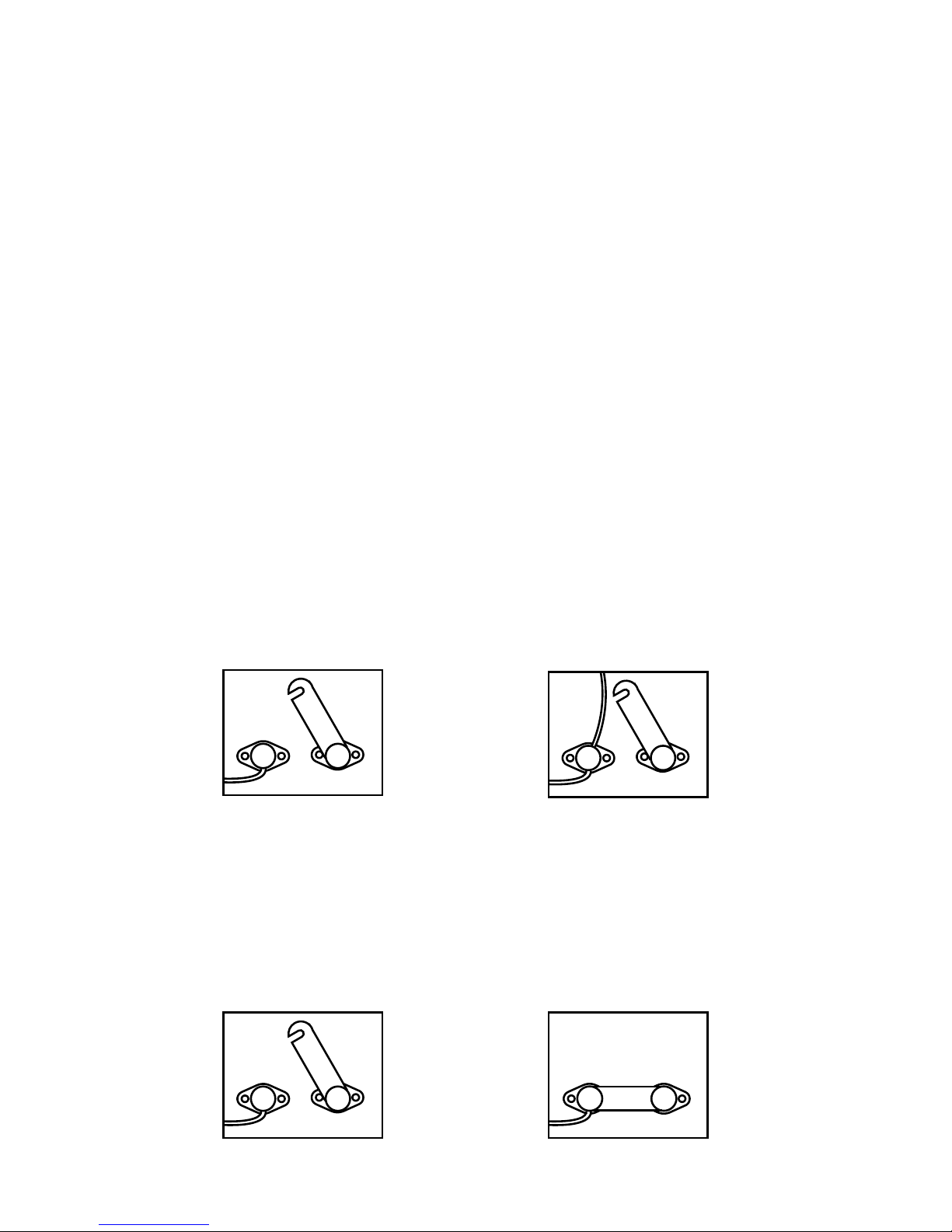
Ground Jumper - IN - Basic Operation
The Basic Operation does not provide additional isolation. For basic
operation be sure the jumper is in place between the Chassis Ground
and Amplier Ground. This is the shipping conguration.
NEVER OPERATE WITHOUT THE JUMPER OR A GROUND WIRE
ATTACHED.
Ground Jumper - OUT - Enhanced Operation
The Enhanced Operation provides isolation for both the DAC and the
Headphone Amplier.
For use with 2-channel system:
This setup is for a system that includes headphone and loudspeaker
playback.
-Disconnect the DAC powerbase and headphone amplier grounding
bridges.
-Attach a ground wire between the ‘Amp Ground’ lugs on the powerbase
and headphone amplier.
-Attach a ground wire between one of the ‘Amp Ground’ lugs and
only one loudspeaker amplier chassis ground. This connection is
dependent on the amplier so you will have to look for the best place
to attach the wire to chassis ground.
MSB
Amp
Ground
Chassis
Ground
MSB
Chassis
Ground
Amp
Ground
For use as Select Headphone system ONLY:
This setup is for a system that is for headphone playback only.
-Disconnect the DAC powerbase grounding bridge.
-Attach a ground wire between the ‘Amp Ground’ lugs on the powerbase
and headphone amplier.
-Connect the grounding bridge on the headphone amplier.
MSB
Amp
Ground
Chassis
Ground
MSB
Amp
Ground
Chassis
Ground
(Powerbase Connections)
(Headphone Amplier Connections)
(Powerbase Connections) (Headphone Amplier Connections)
Page 6
1
2
3 4 5 6 7 8
9
10
11 12
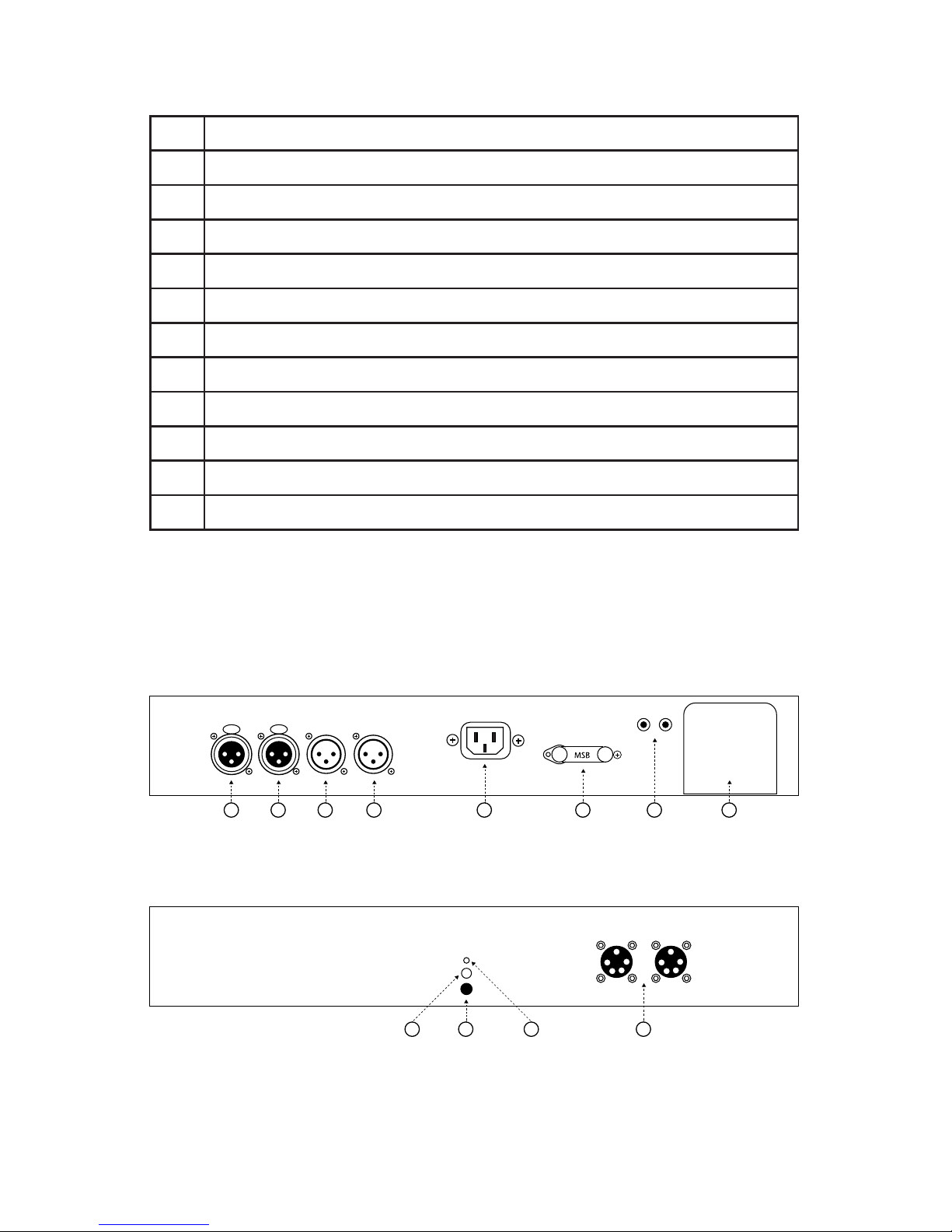
(Select Headphone Amplier Jack Panel)
(Select Headphone Amplier Face Plate)
1 Balanced Analog Input (Right Channel)
2 Balanced Analog Input (Left Channel)
3 Balanced Analog Output (Right Channel)
4 Balanced Analog Output (Left Channel)
5 Power Input 120-240 VAC
6 Grounding Lugs
7 12 Volt Trigger
8 Optimization Module Slot
9 On/O Button
10 IR Sensor
11 Indicator LED
12 Stax Headphone Outputs (2X)
User Interface
Page 7
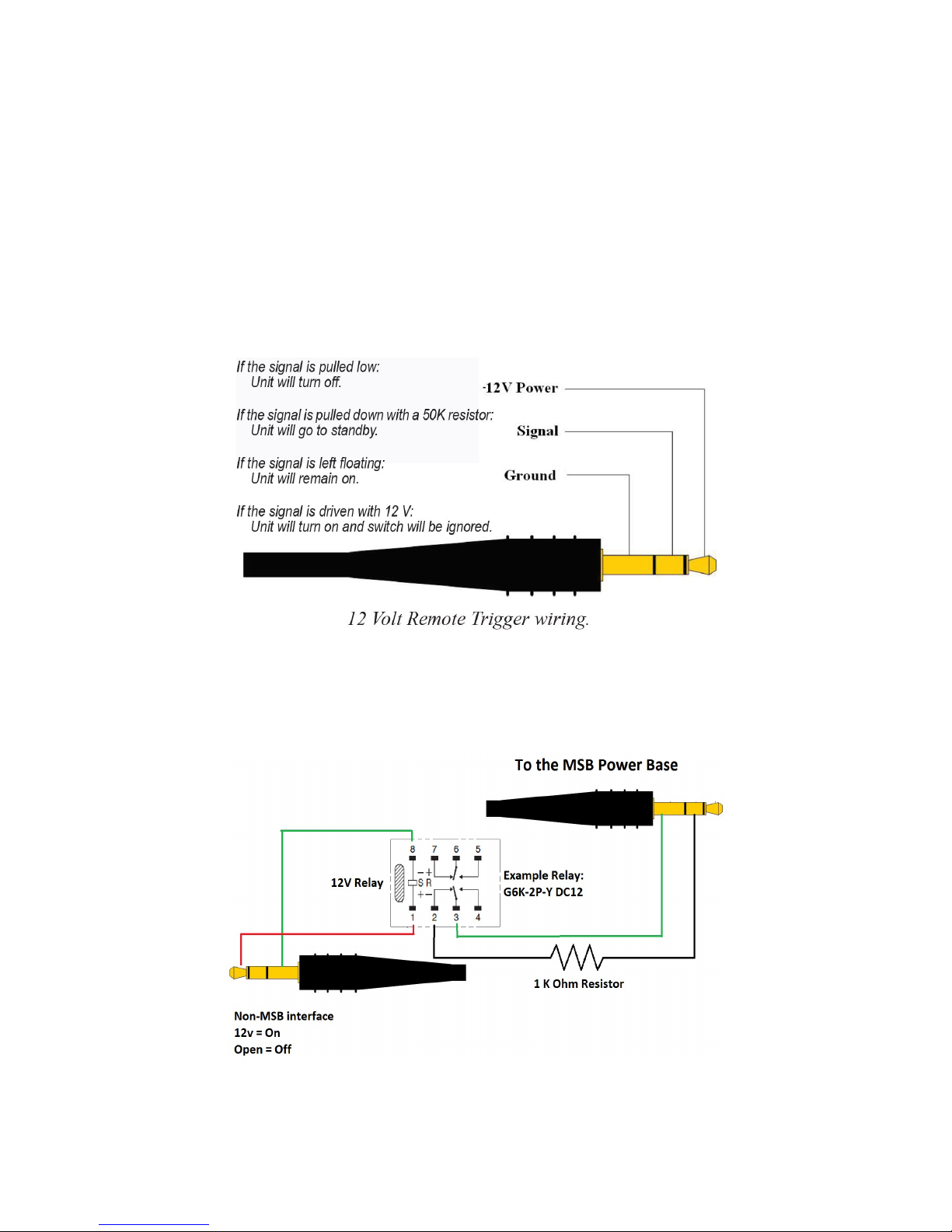
12 Volt Remote Trigger
This powerbase is equipped with a remote trigger for use with other
MSB products. The trigger uses a 3 pin mini jack. When any MSB
product is turned o, the other products connected will also turn
o and vice-versa. This trigger can also be used with other products.
Products may use this trigger dierently, so you may need to rewire
a cable or use an interface relay. The connector is wired as shown. If
you connect “signal” to “ground”, all MSB products will turn o. If you
connect “signal” to “12 V” or leave it open, all MSB products will turn
on.
Page 8
Technical Support
If you are experiencing any issues with your MSB product, please contact
your nearest dealer or try our support page at www.msbtechnology.
com/support. Please be sure you have the most current edition of your
products rmware installed. If your issue persists please feel free to
contact MSB directly. Emails are usually responded to in 24 - 48 hours.
Email: [email protected]
MSB Return Procedure (RMA)
If a customer, dealer, or distributor has a problem with an MSB
product, they should email tech support before sending anything
back to the factory. MSB will do their best to respond within 24 hours.
Should it be clear that a product must be returned, tech support
should be informed and all the following relevant information should
be provided:
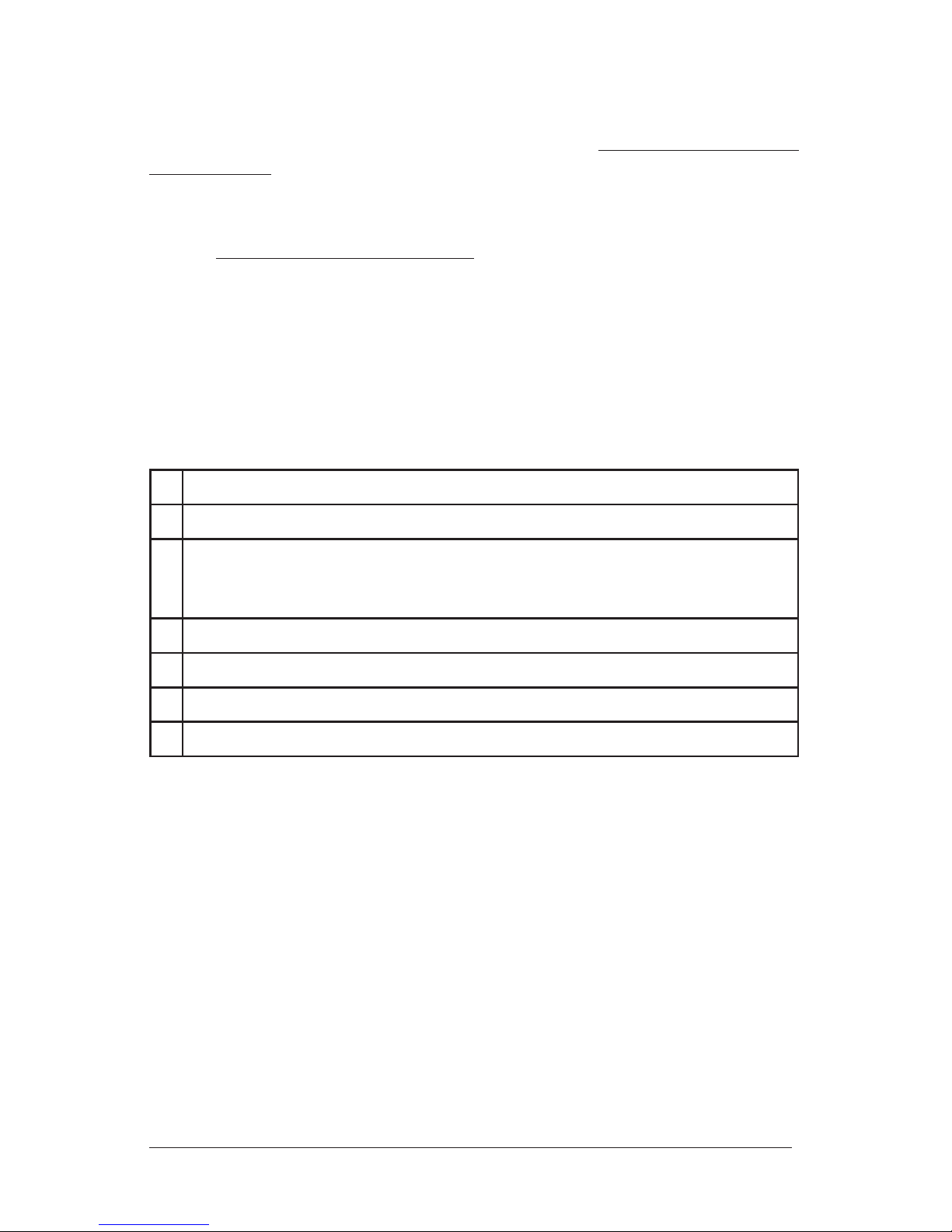
1
Product in question
2
Serial number
3
Exact conguration when symptom is observed along with a list
with the input used, source material, system connections, and
amplier
4
Customer name
5
Customer shipping address
6
Customer phone number and email
7
Special return shipping instructions
MSB will issue an RMA number and create an invoice with all details
outlined except the nal price as the product has not yet been seen.
This invoice will be emailed so all the above information can be checked
and veried by the customer.
The product should be returned with the RMA number present on the
box. Work can then begin immediately and the product can be sent
back quickly.
Any repair that is dicult and cannot be completed in two weeks will be
identied and the customer will be informed when it is to be expected.
Otherwise the majority of repairs should be shipped back within two
weeks if all the required information is present on the invoice.
Link to page:
http://www.msbtechnology.com/faq/msb-product-return-procedure/
Page 9

The Select Headphone Amplier Limited
Warranty
Warranty includes:
• MSB warrantys the unit against defects in materials and workman-
ship for a period of 10 years from the date the unit was originally
shipped from MSB.
• This warranty covers parts and labor only, it does not cover shipping
charges or tax/duty. During the Warranty period, there will normally
be no charge for parts or labor.
• During the warranty period, MSB will repair or, at our discretion,
replace a faulty product.
• Warranty repairs must be carried out by MSB or our authorized
dealer. Please contact your dealer if your unit requires service.
Warranty excludes:
• The Warranty does not cover standard wear and tear.
• The product is misused in any way.
• Any unauthorized modications or repairs were performed.
• The product is not used in accordance with the Operating Conditions
stated below.
• The product is serviced or repaired by someone other than MSB or a
authorized dealers.
• The product is operated without a mains earth (or ground) connection.
• The unit is returned inadequately packed.
• MSB reserves the right to apply a service charge if the product
returned for warranty repair is found to be operating correctly, or if
the product is returned without a returns number (RMA) being issued.
Operating Conditions:
• Ambient temperature range: 32F to 90F, non-condensing.
• The supply voltage must remain within the AC voltage specied on
the power base.
• Do not install the unit near heat sources such as radiators, air ducts,
power ampliers or in direct strong sunlight.
 Loading...