

Page 1
Users Manual
Rev 2 (4/01)
Nelson
Page 2
Thank you for purchasing the world famous LINK DAC III. W e are sure you will be
very pleased with it. The Nelson LINK III includes several new features which significantly improve performance over the LINK III.
At least 100 hours of burn-in is required on this DAC. Customers generally recommend one month.
Setup and Quick Start
The front panel is quite simple with no user controls. LEDs indicate power, the input
source, the sampling frequency and whether the upsampling option is on or off.
Power
The LINK comes standard with an outboard desktop power supply. However, this
supply does limit the sonics of the unit and the P1000 Power Base is recommended. It
is intended to sit directly under the LINK. It will supply the power, and most importantly, the instantaneous current demands of the high slew-rate op amps used in this
product.
Inputs
The Nelson LINK III comes standard with AES/EBU balanced, coaxial and optical
digital audio inputs, ranked in order of performance. An analog input is also provided
for A/B testing and special applications. Connect any digital input to any active digital
audio source. The relays inside will click, as the analog bypass is disconnected.
Outputs
Connect the analog outputs to any passive or active volume control and audio should
be present.
The upsampling switch on the rear panel can be used to upsample any input source to
96K. The option LED lights when upsampling is on. The higher sampling rate is also
indicated on the frequency LEDs.
2
Standard Configuration - As shipped
Upsampling Frequency: 96K 132K
Balanced Input: AES/EBU MSB Network (192k)
MSB Network Channel 1st (Front) 2nd, 3rd, 4th
Data Inversion: Normal Inverted
Zero Option: On Off
Analog Filters: On Off
Each option is described in detail later in the manual.
Page 3
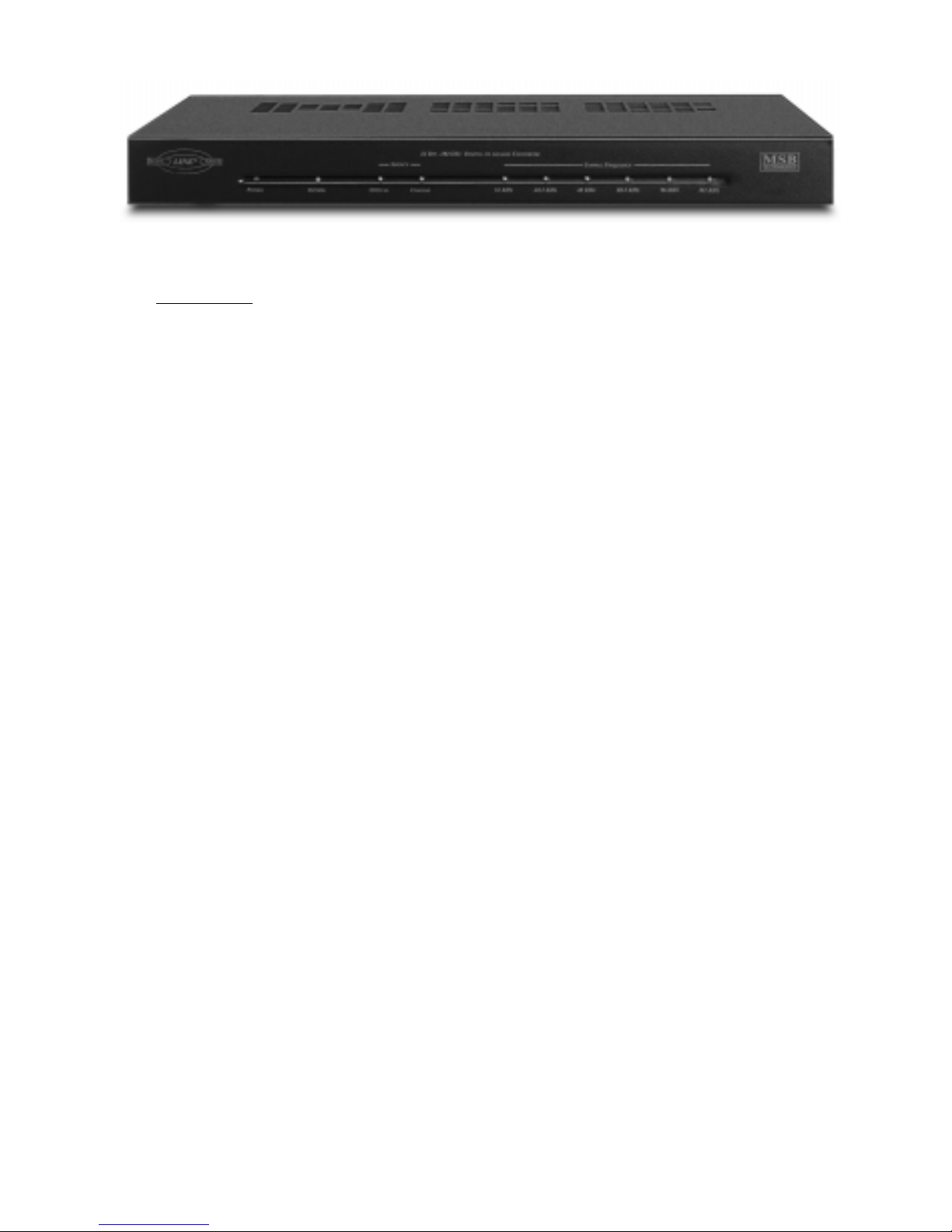
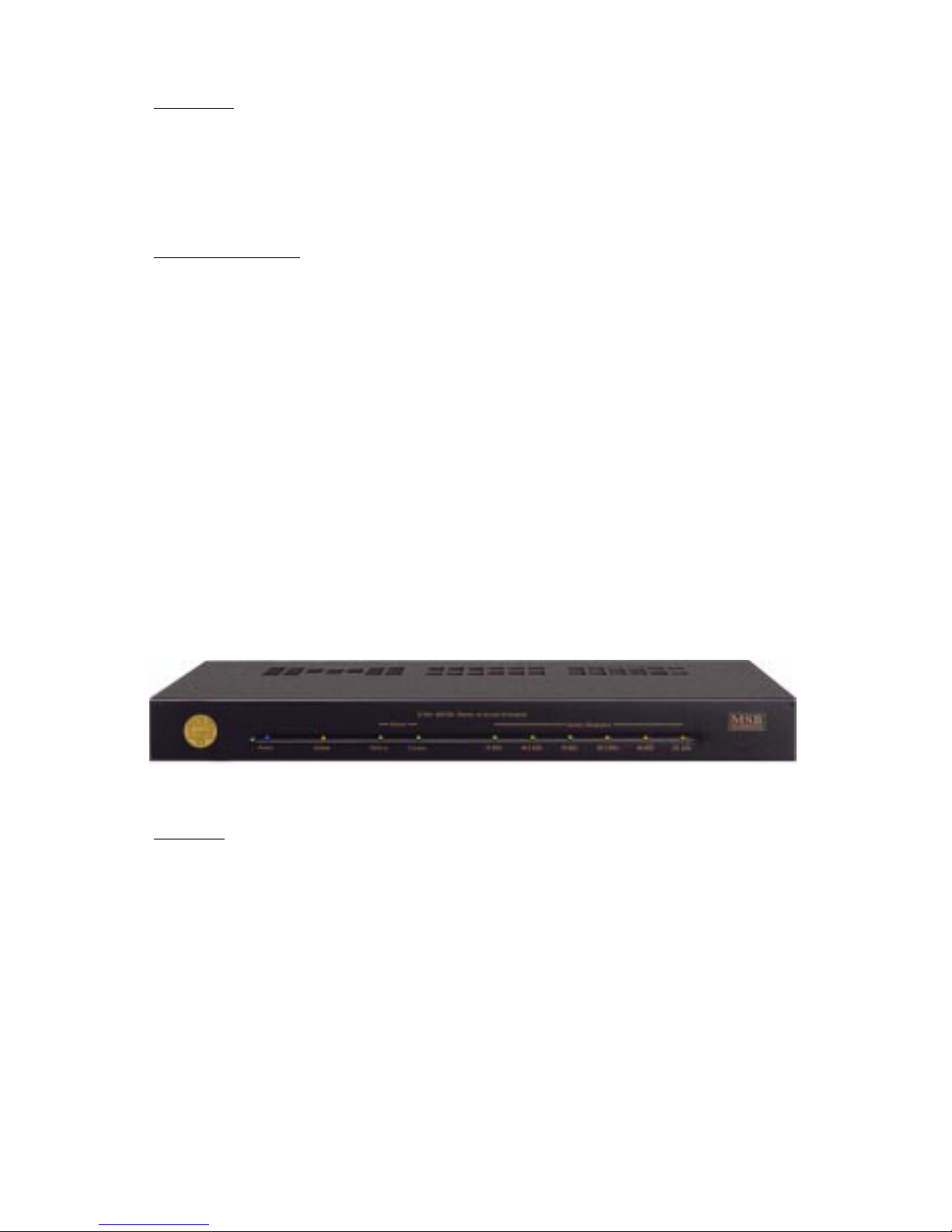
Front Panel
The front panel is quite simple with no user controls. LEDs indicate power, the
input source, the sampling frequency and whether an option is installed and is
active.
Power - The blue power LED lights up any time power is applied. The LINK should
always be left plugged in with the blue LED lit.
Option - The option LED will never light unless an option is installed. It indicates
a specific function for each option, such as upsampling or HDCD. It will light in the
full brightness and half brightness mode for further differentiation between multiple options. The Nelson LINK comes with upsampling installed, so the option
LED will light whenever the upsampling toggle switch on the back panel is turned
on.
Source - Both the coaxial and optical inputs are indicated on the display with
separate LEDs. When an active digital signal is attached to the LINK III the LED
will light, even if no music is playing, or the source is data (like Dolby Digital or
DTS). If both sources are active, both LEDs will light, but the COAXIAL input will
take priority. If a balanced or 192k input is sensed, that input takes priority over
both single-ended inputs but no indication is made on the input LEDs. They
continue to indicate that status of the single-ended inputs.
Sample Frequency - These LEDs indicate the incoming sampling frequency , whether
music is playing or not, and whether the source is data or not. When upsampling is
selected, the LEDs indicate the frequency of the upsampled data, not the source.
As no LED was provided for 132k, no LEDs light when upsampling to 132k, but the
option LED reminds you that upsampling is on. The 192 LED will not light without
a 192 source present on the balanced input, and the proper setup configuration
made inside the unit.
3
Page 4
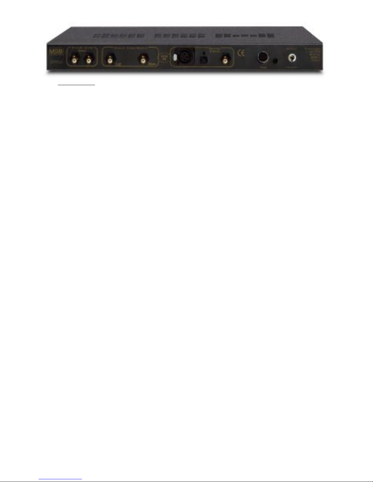
Back Panel
The back panel contains the interface connectors and one toggle switch.
Analog Audio Input - The analog input provides a high quality pass-through switch-
ing feature that has many applications. In other words, the pass-through connections are made unless a digital input is active. Active means that the source
plugged in is powered on, but not necessarily playing. This feature can be changed
to only switch when nonzero digital signals are present. In this case the analog
input is only interrupted when the digital source is playing, not just turned on. This
option is specifically designed for use with C and Ku satellite receivers such as the
4DTV receiver . To configure this option, see the setup section.
Analog Audio Outputs - The LINK III outputs a standard 2V RMS at 0 dB. The
output impedance is 330 ohms.
Balanced Digital Input - The balanced input has the highest input selection priority. Over our many years of producing high-end audio products we have found
that the AES/EBU balanced professional digital audio format consistently outperforms all others for tonal accuracy , focus and image stability. As all DACs derive
their clocks from the incoming digital bit stream, the quality and accuracy of the
source, transport and interconnections are very important. This format offers the
lowest jitter for two reasons. First, because the actual voltage level of the signal is
10 times greater than SP-DIFF . Secondly, as a balanced system, noise rejection is
complete. Noise on a digital interface shifts the digital translations, increasing
jitter. If you do not have a good transport with a balanced digital output, MSB
offers a balanced digital output upgrade to any digital source. Only the balanced
or MSB Network can be selected by internal configuration to work at one time.
MSB Network Input - Although the MSB Network operating at 192kHz uses the
same connector as a balanced digital audio connection, several significant differences exist. Most importantly , the cable must be of a twisted pair construction, not
of a coaxial nature. Wire such as CAT5 is perfect for the MSB Network. The other
significant difference is that clocks and data are actually sent separately in the
MSB network, like Audio Alchemy’ s old I2S interface. This results in greatly improved performance, even with CD playback. This input will not work without an
internal configuration change and will dissable the balanced input.
Single Ended Digital Inputs - Both a T oslink optical and Coaxial Digital audio input
are provided. Autodetection selects either active input. If both are active, the
Coaxial input is selected. Active inputs are indicated with front panel LEDs.
T oggle Switch - The toggle switch down leaves upsampling off. Up turns upsampling
on.
4
Page 5
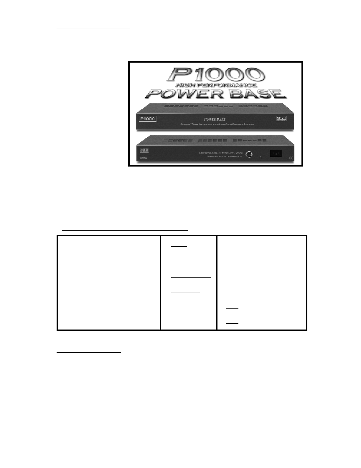
Power Supply Upgrades
This is supplied with an outboard desktop power supply . This supply does limit the
sonics of the unit and the P1000 Power Base is really recommended . This heavy
duty supply is based
on a large triple wound
toroidal transformer.
It is intended to sit directly under the
LINK. It will supply
the power, and most
importantly, the instantaneous current
demands of the high
slew-rate op amps
used in this product.
Configuration Options
Inside the LINK III are several headers with jumpers installed. They change various
functions of the LINK III and allow upgrades to be installed. Several options can be
set by the user as shown in the table below. Each is described in detail.
Opening the LINK III
Place the LINK III on a soft surface like a tablecloth or carpet. Disconnect the power
supply . Remove the three philips screws on the back edge of the cover. Turn the
LINK over and remove the three philips screws from the front edge of the cover.
Carefully separate the base from the cover . Pick up the base and flip it over, placing
it inside the cover . Take care not to disconnect the ribbon cable to the front panel.
Place the LINK so that the RCA connectors are facing A WAY from you. This way
all the diagrams will be oriented correctly .
Standard Configuration - As shipped
Upsampling Frequency: 96K 132K
Balanced Input: AES/EBU MSB Network (192k)
MSB Network Channel 1st (Front) 2nd, 3rd, 4th
Data Inversion: Normal Inverted
Zero Option: On Off
Analog Filters: On Off
5
Page 6

6
System Configuration
Basic Upsampling
The toggle switch installed on the rear of the LINK allows upsampling to be turned
on or off. The option LED on the front panel indicates “Upsampling on”. The basic
upsampling provides a new digitally sampled signal at 96 kHz. This signal is decoded by the internal LINK DAC at 96K and the 96K LED will also light up ONL Y
when an active source is being played. When no source is active, such as when a
CD is paused, the input LED will light, but the frequency LED will not light. As soon
as play is resumed the frequency LED will again light up. This is different from a
LINK DAC without upsampling. It indicates frequency even if the source is not
actively playing.
Higher Rate Sampling
An extra oscillator is installed on the upsampling board, and can be selected instead
of the standard oscillator to increase the sampling rate from 96 kHz to 132.3 kHz (3
times the CD rate of 44.1 kHz). This is the highest rate the LINK III can upsample to.
No frequency LED lights up when the 132 kHz fr equency is selected. Admittedly,
we are driving both the decoder and DAC beyond their design limits, but our
experience at normal room temperature conditions has shown the higher speed
upgrade too works very well. If your environment is too hot (the LINK sits on top
of your amplifier), you may need to install the normal 96K oscillator .
To change the frequency, follow the instructions to open the cover of the LINK.
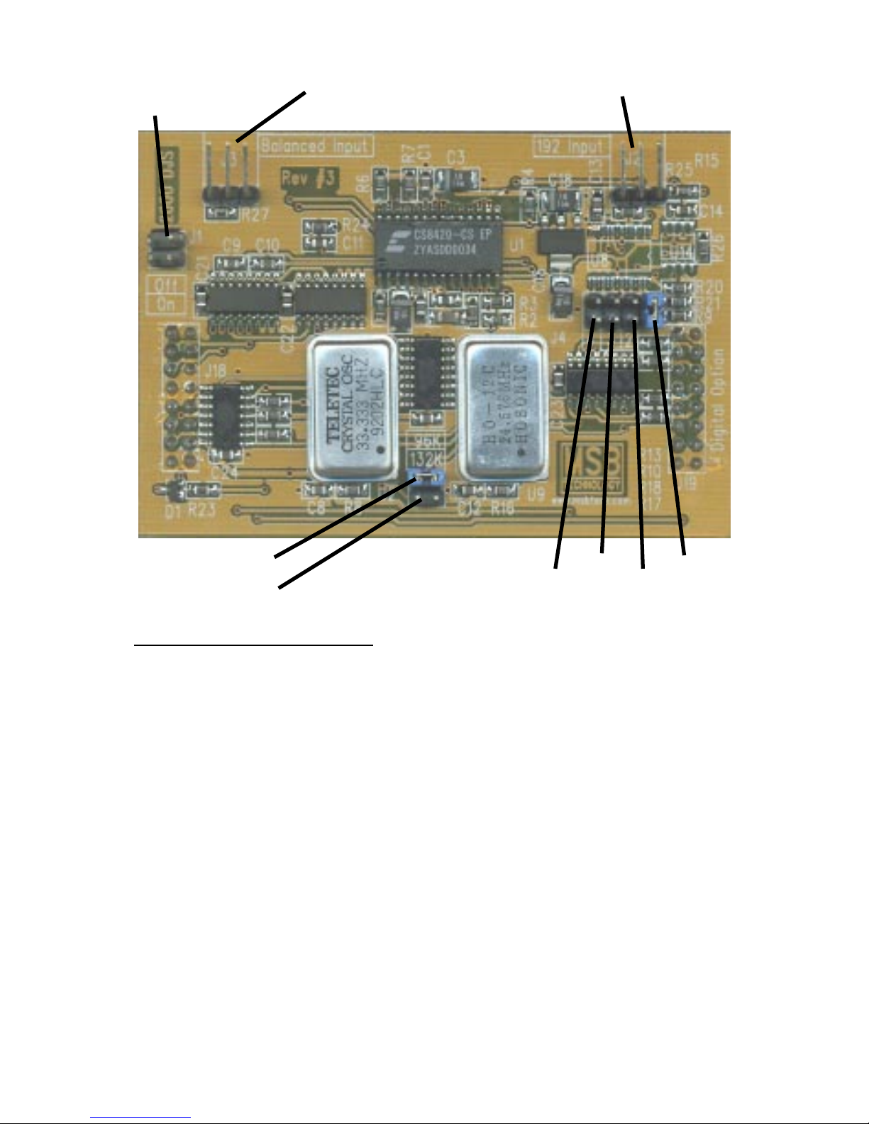
Inside the LINK notice the small upsampling board installed in the main board,
shown below . Two jumper positions are available between the large metal oscillators. They are labeled 96K and 132K. As shipped, the jumper is located in the 96K
position. Remove the jumper and move to the 132K position.
Balanced Input Selection
The XLR input can be used as either an AES/EBU balanced digital audio input or as
the MSB Network (192 kHz) input. As an AES/EBU input it can be attached to any
standard transport that provides a XLR digital output. It can handle all the same
sources as the single-ended inputs but with better audio quality.
As an MSB Network Input, it can only be attached to Transports with MSB Network outputs, which include DVD-A transports with the MSB modification or any
digital source with the MSB 192 kHz upsampler upgrade. It must be connected with
a twisted pair cable such as CA T5. Most audiophile balanced cables will NOT work
with the MSB network.
To change the input, open the cover. Unplug the cable running from the XLR
connector to the Upsampling board and switch to the adjacent connector. From the
factory it is plugged into the connector labeled “Balanced Input”. For the MSB
Network, move it to the connector labeled “192 Input” (see diagram).
Page 7
BALANCED INPUT
MSB NETWORK INPUTUPSAMPLING SWITCH
96K UPSAMPLING
132K UPSAMPLING
CH 4
CH 3
CH2
CH 1
MSB Network Channel Selection
The MSB Network supports 4 stereo channels of 192k data at once. Any DAC can
be configured to decode any of these 4 channels. For example, when an upgraded
DVD player is playing a DTS music CD, one DAC can be configured to Channel 1
and will receive the front channels. A second DAC can be attached to the same wire
at the same time and by selecting Channel 2 will receive and decode the rear channels. The 3rd channel is for the front and sub channels if you want to use them. The
4th channel is for future formats which may come along. Move the jumper located
on the upsampling board as shown in the diagram to select the channel.
More than one DAC can be attached to the same cable by taking advantage of a
DAC with both an input and output like the Platinum to create a daisy chain configuration. A MSB Network output upgrade provides three identical connectors
allowing three DACs to be driven at once, each set up for a different channel.
7
Page 8
8
Phase Invert
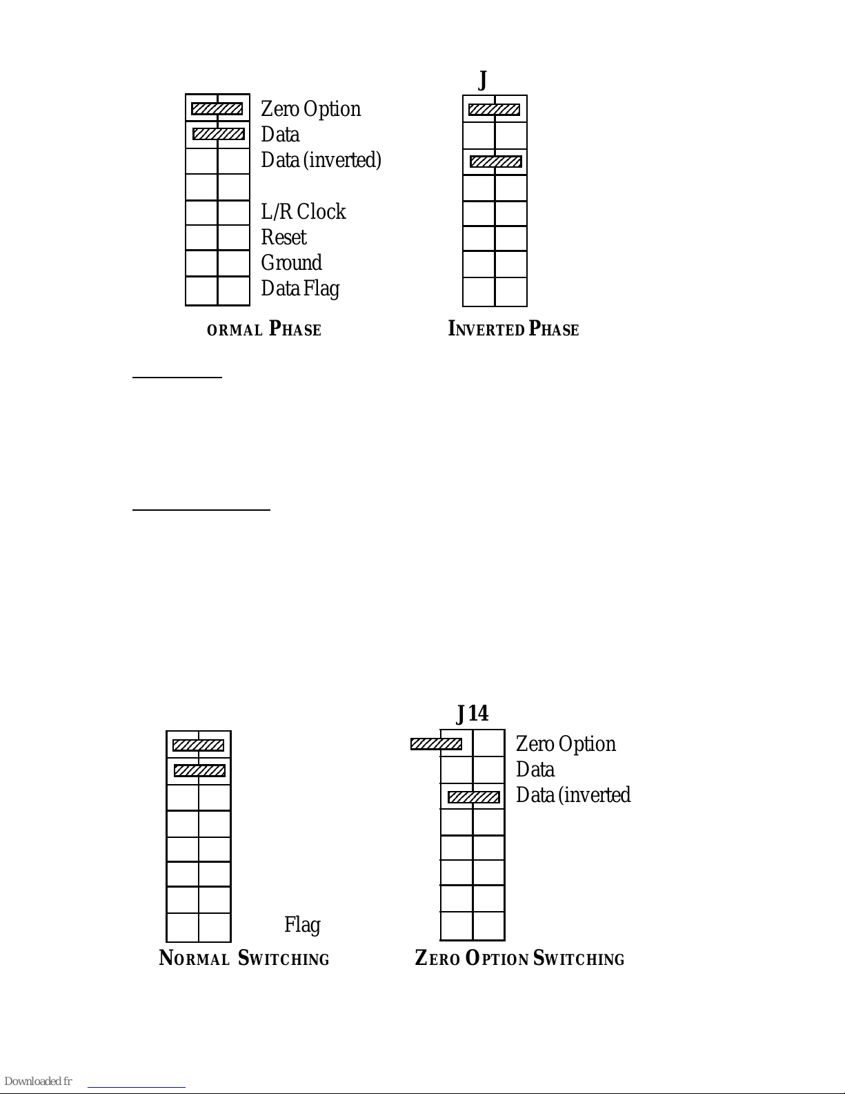
Phase invert is permanently set inside the LINK III. Locate the header labeled J14.
The jumper can be placed in either the Data or Data (inverted) position. If you want
to be able to switch phase invert from the back panel, a toggle switch is available
that can be installed to J14. Upsampling would then be selected with fixed jumpers.
Digital Zero Option
The analog bypass is normally interrupted when a digital input is active. Active
means that the source plugged in is turned on, not necessarily playing. This feature
can be changed to only switch when nonzero digital audio signals are present. It
will ignore data such as Dolby Digital and DTS signals. In this case the analog
input is only interrupted when the digital source is playing valid audio, not just
turned on. Remove the first jumper on J 14 labeled “Zero Option”. The jumper may
be placed on just one pin for future use.
J14
23456789
0
23456789
0
Zero Option
Data
Data (inverted)
L/R Clock
Reset
Ground
Data Flag
J14
23456789
0
2345678
9
Zero Option
Data
Data (inverted)
L/R Clock
Reset
Ground
Data Flag
NORMAL PHASE INVERTED PHASE
J14
2345678
9
2345678
9
Zero Option
Data
Data (inverted)
L/R Clock
Reset
Ground
Data Flag
J14
2345678
9
Zero Option
Data
Data (inverted)
L/R Clock
Reset
Ground
Data Flag
NORMAL SWITCHING ZERO OPTION SWITCHING
Page 9
9
DSP Headers
1
2
3
4
5
6
7
8
J18
J19
2345678
9
2345678
9
23456789
0
23456789
0
23456789
0
23456789
0
Ground
Data
Bit Clock
L/R Clock
M Clock
Data Flag
Ground
Ground
S/PDIF
S/PDIF (inverted)
Ground
Digital Active
Option 1
192 kHz
Ground
2345678
9
2345678
9
NORMAL POSITION OF LINK III JUMPERS
Analog Filter Change
The analog filters in the output stage can be adjusted. The Nelson is normally
configured with the filters disabled. This does not comply with the common practice of rather heavily filtering the outputs to achieve perfect measurements. It is
instead set up to sound better, at the expense of perfect measurements. For those
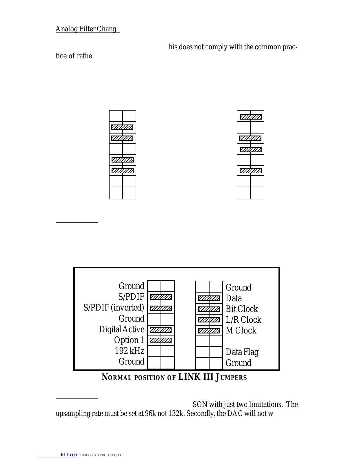
who prefer greater dynamics and attack, leave the jumpers from positions 2 and 5 of
J16 out. They should be placed on positions 1 and 4 for safe keeping. For a
smoother sound, try moving the jumpers from 1 to 2 and from 4 to 5.
Other Options
Headers J18 and J19 are occupied by the upsampling board. Should this board
need to be removed for some reason, jumpers can be installed to allow the DAC to
operate. The standard jumper positions are shown below for reference. Any
missing jumpers will prevent the LINK III from working.
1
2
3
4
5
6
7
8
J16
123456789
12345678
9
123456789
123456789
12345678
9
123456789
123456789
1
2345678
9
123456789
123456789
1
2345678
9
123456789
Ground
L Filter 1
L Filter 2
Ground
R Filter 1
R Filter 2
Ground
+8V, -8V
1
2
3
4
5
6
7
8
J16
2345678
9
23456789
0
2345678
9
123456789
1
2345678
9
123456789
Ground
L Filter 1
L Filter 2
Ground
R Filter 1
R Filter 2
Ground
+8V, -8V
NORMAL FILTERS REDUCED FILTERING
HDCD Option
The HDCD option can be installed in the NELSON with just two limitations. The
upsampling rate must be set at 96k not 132k. Secondly , the DAC will not work with
192K sources with the HDCD option installed.
Page 10
10
Operation
The operation of the LINK III is fully automatic. The LINK now autoswitches with
the following priorities: The balanced input is first, coaxial second, optical third
and the analog pass-through is the default condition. The analog pass-through is
of very high quality and is great for comparing analog and digital sources.
How far can it go?
W ith the addition of the P1000 power base we think this product is the best sound
you can get from a LINK. To go beyond, please consider the Gold or Platinum
LINK. MSB generally offers a full trade in credit when upgrading to the Gold or
Platinum. The Gold Link DAC uses four internal stereo D-to-A converters. T wo
individual pairs of DACs are used for each of the right and left channels. The
improved signal isolation from using separate DACs delivers superior channel
separation. Our unique four DAC system results in amazingly accurate, live sound
without the brightness found in so many of the current D-to-A strategies.
The Gold has a minimum of output filtering for the best possible sound. It features
electromagnetic shielding of all key components and high performance, high slewrate operational amplifiers. Seven separate power supplies with gigantic filter
capacitors provide isolation between the digital and analog sides of the DAC.
“I love this digital to analog maker of music… It’s almost mystical in its presence
and realism.” Martin G. DeWulf, . Bound for Sound Report
Software
V irtually all PCM digital sources can be decoded including 24/96K and 24 bit 192K
(DVD-A) and 20 bit 96K six channel (DVD-A). The frequency of the incoming
signal is indicated on the front panel with LEDs. Note that many DVD players play
96K-24 bit DVDs but output at 48 kHz. Some players offer a menu option to select
96K but many do not. To get the true 96K output a 96K digital output upgrade is
available from MSB. DVD-A players do the same thing. Only with an MSB upgrade can true 192 digital audio be output. Discussion of adding copy protection
is always underway in an AES working group. Should decryption be required to
play back new software, an upgrade board will be offered at a reasonable price to
plug into the LINK’ s upgrade sockets.
Page 11

Troubleshooting
No “Source” indicated - Is the 132k upsampling feature on? Is the balanced input
active? Both can result in no source LED lit. Next, check for bad cable, or cable
plugged into the wrong output on the transport.
No sound - Check that source is valid audio source. Change to a standard CD just
to be sure. Check that analog outputs are connected to the “outputs” not the
“inputs”.
Still no sound - connect an analog output from the source directly to the volume
control. Verify that the rest of the system is working. Now move the same analog
output to the analog input on the LINK. Add a new cable from the analog output to
the volume control. Disconnect the digital inputs and confirm that the system still
works. Now plug in a digital source. You should hear a click and the front LEDs
should light.
96K source indicates 48k on front panel - Check setup menu of DVD player . Digital
output should be set for 96k output. Some models do not support this feature.
DVD-A source indicates 48k - DVD-A players must be upgraded to provide a true
192K output. Production players downmix to 48K.
Balanced Input not working - Check configurations - is XLR connector plugged
into balanced or 192k input.
Warranty
All MSB products carry a one year warranty . No returns accepted without an RMA.
Upon receipt, MSB will repair or replace any defective product. All product shipped
FOB La Honda. Shipping is the responsibility of the consignee.
11
SPECIFICATIONS: NELSON LINK III
INPUTS:COAXIAL, TOSLINK, BALANCED AES/EBU AND
MSB NETWORK (192K)
OUTPUTS:LINE LEVEL 2.5 VRMS
SAMPLING FREQUENCY: 32 TO 192 KHZ
DAC: BURR BROWN
SLEW RATE: 1000 V/MICROSECOND
SETTLING TIME: <9 NANOSECONDS
LOW VOLTAGE NOISE:9 NV/HZ
.5
DYNAMIC RANGE: 109 dB
THD+N: 96 dB
SIGNAL TO NOISE RATIO: 1 15 dB
CHANNEL SEPARATION: >95 dB
FREQUENCY RESPONSE: DC - 22 KHZ
UPSAMPLING: 96 KHZ AND 132 KHZ
WEIGHT AND DIMENSIONS: 18 LBS, 17”W X 14”D X 1.75”H
RACK MOUNTABLE WITH EXTERNAL POWER SUPPLY (120V OR 220V)
Page 12

The GOLD LINK DAC provides an unparalleled sound experience with virtually any
available digital source. Four internal stereo DA converters give improved signal-to-noise
and channel separation characteristics, providing outstanding signal quality to your
preamplifier. The Gold has little output filtering for the best possible sound, electromagnetic
shielding of all the key components and high performance, high slew rate operational
amplifiers. This DAC delivers incredible “focus” and depth of soundstage to the listening
environment. Includes the same upgrade features as the Nelson DAC.
MSB GOLD LINK DAC
MSB Platinum Link DAC
This 46 bit - 384 kHz sign magnitude R2R ladder DAC with four independent discrete
converters goes way beyond any other DAC. It can handle greater resolution and higher
sampling frequencies than any existing format, for maximum S/N and channel isolation. The
Platinum upsamples lower sampling rate sources to 24 bit - 96 kHz. It has up to 5 digital
inputs (ATT glass, Toslink optical, Coaxial SP/DIF, Balanced AES/EBU and MSB Network) as well as balanced and single-ended analog outputs. Selectable digital filter response
(interpolation and slope) give you complete control. The painstaking detail, care and phenomenal sound you demand from a high-end DAC.
HIGH QUALITY, AFFORDABLE CABLE P RODUCTS
6 RCA to DB-25
Digital Audio
AC3-RF - for LD
Audio - Triple Shielded
S-Video - 2m
Video
Toslink Optical 1m - also 2m, 15m
Red Hawk Optical 1m - also 3m, 20m
MSB Custom Digital
MSB Interconnects
This upgrade installs in most digital products and provides a 192 kHz audio output compatible with the LINK III family of DACs. Installs in DVD-A players, standard DVD, CD,
LD players as well as DSS systems. All sources are upsampled to 192 kHz. Multichannel
output also possible on DTS and Dolby Digital equipped players.
The Professional Analog-to-Digital Converter does for your analog system what the LINK
DAC does for your digital system. Use it to create high resolution digital audio CDs or
DVDs from your vinyl. The MSB PAD allows you to convert analog sources to a variety
of noise resistant digital audio formats for input to your PC, recorder, equalizer/processor,
or digital playback system for the cleanest possible sound! The balanced professional inputs
and output of this product make it a cost effective addition to any studio, large or small. The
balanced analog, dedicated phono and standard line level inputs are selected from the front
panel. The PAD outputs 44.1, 48, 88.2 and 96 kHz sampling frequencies with a staggering
120 dB dynamic range.
192K UPSAMPLER UPGRADE
PRO A - D CONVERTER
C
ONVERTS ANALOG SOURCES INTO
24/96 D
IGITAL AUDIO
MORE WAYS TO ACHIEVE
INCREDIBLE SOUND... FROM MSB
 Loading...