

Page 1

The 500 Series
Amplier
User Guide
Check our website for the most recent user
guides, rmware, and drivers:
www.msbtechnology.com
Technical support email is:
10.15.2019
Page 2

Page 3

Technical specications
Static Power
Consumption
Input 2x XLR Input 1x XLR Input
Output 1x Binding post
Cont. Power Output (4Ω)
< 1% distortion
Cont. Power Output (8Ω)
< 1% distortion
Frequency Response
(20 to 20kHz)
Signal to Noise
(20 to 22kHz)
Equivalent Input Noise
(22kHz BW)
Low Gain
(75Ω source impedance)
Medium Gain
(75Ω source impedance)
High Gain
(75Ω source impedance)
Input Impedance
(User Selectable)
Output Impedance
(20 to 20kHz)
Operating
Voltage Range
Fuse 1/4”x1-1/4” 15A 250V Slow Blow
S500 M500
270 Watts On
Less than 2 watts in
standby
sets per channel
900 W 1000 W
500 W
±0.025dB
>134dB (>137dBA)
0.5μV
16.2dB
22.2dB
28.2dB
75Ω / 300Ω / 1.2kΩ
0.07Ω
100V or 105-130V/210-260V
150 Watts On
Less than 2 watts
in standby
2x Binding post
sets per channel
Controls Gain Switch
Input Impedance Switch
On/O Button
Standby Button
Display Dimmer
Delay/Mode Switch
2x MSB 12V Trigger
Page 4
Technical specications (continued)
Chassis Dimensions
(Per Chassis)
Width: 15 in (381 mm)
Depth: 23.25 in (590 mm)
Height: 10.5 in (267 mm)
Weight: 135 lbs (61.25 kg)
Shipping Dimensions
(Per Chassis)
Width: 23 in (585 mm)
Depth: 35 in (889 mm)
Height: 21 in (534 mm)
Weight: 194 lbs (88 kg)
Included Accessories User Manual
IEC C19 Power Cord
Feet
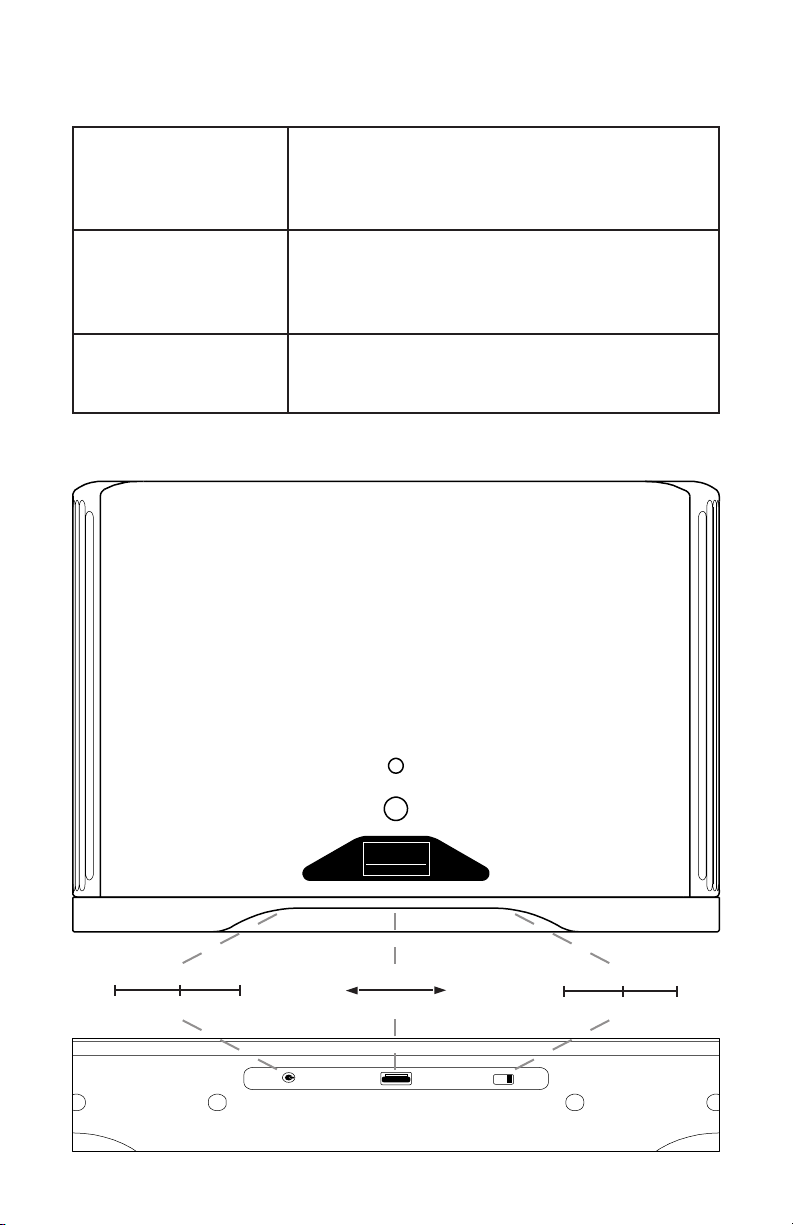
500 Series amplier front controls
STANDBY
POWER
MSB
TECHNOLOGY
Power Control Display Brightness Power Delay
Normal No IR Linked Darker Brighter None Short Long
(Controls under front edge of amplier)
Page 5

Amplier Interface
There are two buttons on the front of the amplier as well as three
control features just under the front of the amplier.
Display Modes All display modes will be displayed at full
brightness when a display status is changed and
then fade to the brightness set by the user.
White
- Power on.
Red
- Power o.
Pulsing Amber
- Standby (pressing the power button from this
state will shut the amplier o, pressing the
standby again will turn it back on)
Flashing Red
- Overheating Protection (Unit will not turn on
until it has reached an acceptable temperature)
Flashing Amber
- Over-voltage protection.
Remote Trigger
Switch
Display
Brightness
Delay switch No Delay
Normal
- This sets the unit as the 12 volt trigger master.
No IR
- Remote commands disabled.
Linked
- This sets the powerbase as the 12 volt trigger
slave. The ‘master’ unit will control this units
power and standby with link cable installed.
This is a rolling wheel to control the brightness of
the power indication display
- The amplier will have no delay before switching
on.
Short Delay
- The amplier will have a short delay before
switching on.
Long Delay
- The amplier will have a long delay before
switching on.
Power
When plugging in power, the amplier detects the input voltage and
automatically switches between 120 or 240 volt operation. It is also
available in a non-switching 100 volt permanent conguration.
Page 6

Connecting to your Amplier
Connect your analog interconnects to the amplier and attach
your speaker cables following the appropriate method below. MSB
recommends to always unplug your amplier when connecting or
changing anything associated with your speaker lugs.
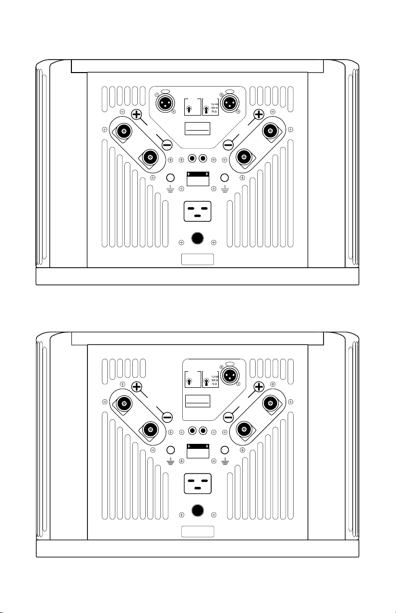
- The M500 Mono Amplier
Each M500 is equipped with two identical sets of audio lugs to allow
exibility in any set up. You only need to make connections to one set
to use the amplier.
- The S500 Stereo Amplier
The S500 is equipped with a ‘Right’ channel and a ‘Left’ channel set of
lugs. Connect your speakers to the associated set of lugs.
Grounding Connections
On each of the 500 Series ampliers there is chassis ground available
just below and to the inside of each set of output lugs. These
grounding connections are labeled with a ground symbol. These are
intended as a simple way to nish the grounding chain setup from an
MSB Powerbase or to attach any shielded audio interconnect grounds.
Never attach any ground wire to the negative terminal of the output
lugs.
Input impedance switch
To select the correct input impedance setting follow the table below.
75Ω MSB Select DAC
MSB Reference DAC
MSB Premier DAC
300Ω MSB Discrete DAC
1.2kΩ All non-MSB Products
(Lower impedance settings can be used, but
contact your products manufacture rst to
ensure that a lower impedance setting will
not damage the product)
Gain setting
To nd the proper gain setting for your system, start with the switch
set to the ‘Low’ setting. If you nd yourself consistently listening at over
100 volume on your MSB DAC, then move the switch up to the next
gain setting. For best performance you should always use the lowest
gain setting that allows you reach a loud enough level for listening
while trying to stay under 100 on your MSB DAC. The gain switch is
intended to achieve optimal matching with your speakers eciency.
Page 7
S500 Stereo Amplier Jack Panel
INPUT
GAIN
IMPEDANCE
HIGH
MED
LOW
RIGHT INPUT
MSB
TECHNOLOGY
S500 STEREO
AMPLIFIER
12 VOLT
TRIGGER
CAUTION
RISK OF ELECTRIC
DO NOT OPEN.
AC INPUT
120 / 240 VOLTS
15 AMP SLO-BLO FUSE
LEFT INPUT
LEFTRIGHT
SHOCK.
Designed and handcrafted in California, USA
M500 Mono Amplier Jack Panel
GAIN
HIGH
MED
LOW
MSB
TECHNOLOGY
M500 MONO
AMPLIFIER
12 VOLT
TRIGGER
CAUTION
RISK OF ELECTRIC
SHOCK.
DO NOT OPEN.
AC INPUT
120 / 240 VOLTS
15 AMP SLO-BLO FUSE
INPUT
IMPEDANCE
INPUT
OUTPUTOUTPUT
Designed and handcrafted in California, USA
Page 8
12 Volt Remote Trigger
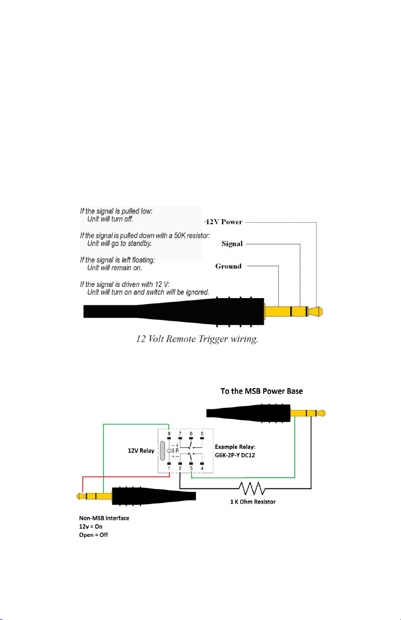
This amplier is equipped with a remote trigger for use with other MSB
products. The trigger uses a 3 pin mini jack. When any MSB product
is turned o, the other products connected will also turn o and viceversa. This trigger can also be used with other products. Products may
use this trigger dierently, so you may need to rewire a cable or use an
interface relay. The connector is wired as shown. If you connect “signal”
to “ground”, all MSB products will turn o. If you connect “signal” to “12
V” or leave it open, all MSB products will turn on. MSB ampliers can
also communicate standby when the ‘signal’ is pulled down using a
50K resistor. Use the power delay switch to stagger the powering on
of the ampliers
Page 9

This page was intentionally left blank by
MSB Technology
Page 10
Technical Support
If you are experiencing any issues with your MSB product, please contact
your nearest dealer or try our support page at www.msbtechnology.
com/support. Please be sure you have the most current edition of your
products rmware installed. If your issue persists please feel free to
contact MSB directly. Emails are usually responded to in 24 - 48 hours.
Email: [email protected]
MSB Return Procedure (RMA)
If a customer, dealer, or distributor has a problem with an MSB
product, they should email tech support before sending anything
back to the factory. MSB will do their best to respond within 24 hours.
Should it be clear that a product must be returned, tech support
should be informed and all the following relevant information should
be provided:
Product in question
1
Serial number
2
Exact conguration when symptom is observed along with a list
3
with the input used, source material, system connections, and
amplier
Customer name
4
Customer shipping address
5
Customer phone number and email
6
Special return shipping instructions
7
MSB will issue an RMA number and create an invoice with all details
outlined except the nal price as the product has not yet been seen.
This invoice will be emailed so all the above information can be checked
and veried by the customer.
The product should be returned with the RMA number present on the
box. Work can then begin immediately and the product can be sent
back quickly.
Any repair that is dicult and cannot be completed in two weeks will be
identied and the customer will be informed when it is to be expected.
Otherwise the majority of repairs should be shipped back within two
weeks if all the required information is present on the invoice.
Link to page:
http://www.msbtechnology.com/faq/msb-product-return-procedure/
Page 11

The 500 Series Amplier Limited Warranty
Warranty includes:
• MSB warrantys the unit against defects in materials and workmanship for a period of 5 years from the date the unit was originally
shipped from MSB.
• This warranty covers parts and labor only, it does not cover shipping
charges or tax/duty. During the Warranty period, there will normally
be no charge for parts or labor.
• During the warranty period, MSB will repair or, at our discretion,
replace a faulty product.
• Warranty repairs must be carried out by MSB or our authorized
dealer. Please contact your dealer if your unit requires service.
Warranty excludes:
• The Warranty does not cover standard wear and tear.
• The product is misused in any way.
• Any unauthorized modications or repairs were performed.
• The product is not used in accordance with the Operating Conditions
stated below.
• The product is serviced or repaired by someone other than MSB or a
authorized dealers.
• The product is operated without a mains earth (or ground) connection.
• The unit is returned inadequately packed.
• MSB reserves the right to apply a service charge if the product
returned for warranty repair is found to be operating correctly, or if
the product is returned without a returns number (RMA) being issued.
Operating Conditions:
• Ambient temperature range: 32F to 90F, non-condensing.
• The supply voltage must remain within the AC voltage specied near
the products AC jack.
• Do not install the unit near heat sources such as radiators, air ducts,
power ampliers or in direct strong sunlight. This may cause the
product to overheat.
 Loading...