

Page 1
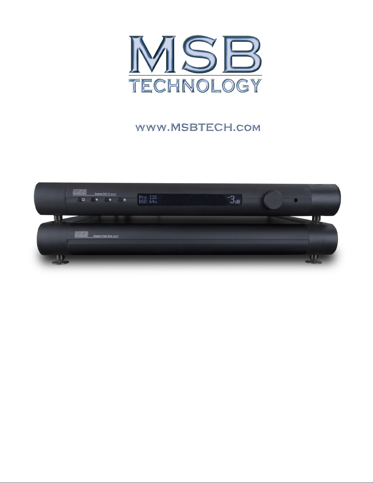
Diamond DAC IV
Users Manual
Rev 1 (4/2014)
1
SELECT
Page 2
DAC IV
SELECT
Users Manual
Unique Product Concept
The Diamond DAC IV select is MSB’s reference DAC for the future. The select model started
life as a fully loaded Diamond DAC IV in which all the options are included as well as an
exciting 10 year warranty and upgrade guarantee. But that is just the beginning. Each month
we add new improvements. Not only does it have the very best diamond DAC modules, Galaxy
Femtosecond Clock, EURO heatsinks, 384 kHz USB input and Diamond Volume controls
-- but now has a number of major improvements including a new heavy duty power link with
additional power supplies to further isolate the clock. It also has lots of hardware improvements
including some new technology we are not even talking about. Its all included, burned in and
carefully tested, including actual listening tests in our reference system. As we are developing
improvements and new ideas, they are immediately incorporated into this DAC, so unlike
normal products, each month the select model will be different, and from time-to-time the
cost may increase. But don’t worry, you can upgrade as often as you want, so you will never
be left behind. The select model comes with a 10 year warranty and upgrade guarantee so as
we make improvements, you can return your DAC and get the latest performance without
having to worry about selling the old model and buying the new one. These upgrades are free
for the rst year and simply the difference in cost between your DAC and the current select
DAC for the remaining years. Guaranteed, no questions asked. Upgrade as often as you like.
DAC and PREAMP Together
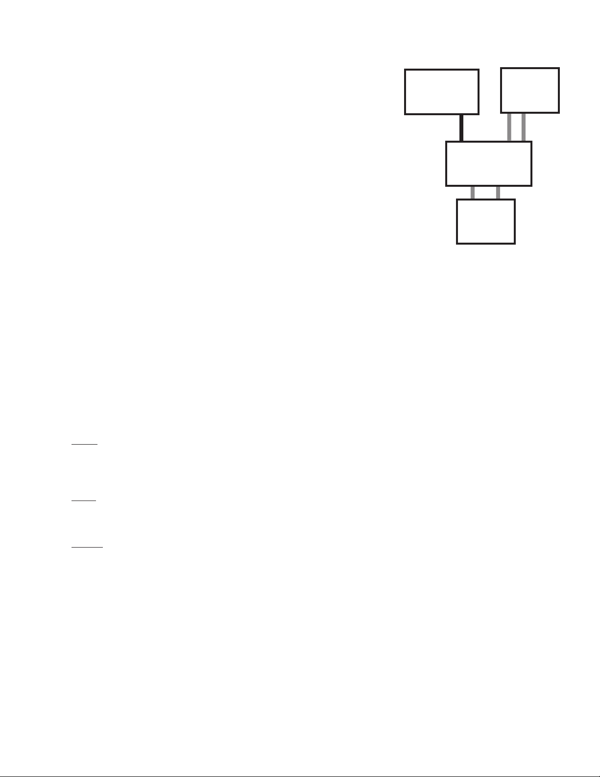
The DAC IV has one analog input with the option for a second, and many digital inputs. It is designed to be the last component in your
system before the ampliers. With its incredibly low impedance, especially for a passive preamp, it can drive long interconnects and
handle any type of amplier input stage design with optimum performance.
Depending on how many analog sources you have in your system, you may be able to eliminate your current preamp. If you currently
have only CD and vinyl in your system, you would attach your CD players digital output to the DAC IV and the output of your phono
preamp to the analog input. Your system is now complete, with the shortest possible signal path and the best sound you can achieve. If
you have a complex system with a preamp with many analog inputs, attach the outputs of your preamp to the input on the DAC IV. Shift
any digital sources over to digital inputs on the DAC IV and again, you will achieve optimum results. Set your preamp to a volume that
matches the DAC IV output and use nothing but the DAC IV volume control in your system.
CD, Universal
Transport
Digital
Phono
Preamp
Analog
R/L
DAC IV
Analog
R/L
AMPs
Setup and Quick Start
The front panel is quite simple with few user controls. Input source select defaults to auto. On power up, the volume
is reset to -30 dB. Turn the volume knob up until you hear music.
Power - The Diamond comes with a high performance outboard power supply. The supply automatically detects and
switches between 240V and 120V. This is not a switching supply that works at any voltage, but a linear supply with
automatic switching of the transformer leads. The power supply is switched on and off with a toggle switch on the
back. It can be remotely controlled when the front panel control option was installed. Always allow three to ve hours
for the Diamond to warm up and reach thermal equilibrium.
Inputs - The Diamond comes standard with one MSB PRO I2S (CAT6), USB2, AES/EBU balanced, coaxial (RCA and
BNC) and optical digital audio inputs, as well as a balance analog input, ranked in order of performance. Connect
any digital input to any active digital audio source. The frequency and bit depth of the incoming signal will be read
out on the front panel and analog audio will be found on both balanced and single-ended analog outputs.
Outputs - Connect the balanced analog outputs to any amplier and audio should be present. If you ordered your
SELECT for single-ended use, there will be no balanced outputs. The output level is controlled with the knob or remote.
Burn-In
The concept of burn-in is little understood. The feedback we receive leads us to recommend at least 100 hours of burn-in on this DAC.
Customers generally report improvement up to one month.
Warning: Please verify that the DAC IV you just purchased is covered under warranty. This DAC was sold to the Distributor named
on your box label. The country and date of manufacture is also specied. If the country and year do not match your purchase
location, your warranty may be invalid. Check with MSB.
PLEASE FILL OUT THE REGISTRATION CARD
The 10 year warranty and UPGRADE Guarantee is ONLY extended to the original owner as registered.
Failure to register puts your warranty at risk!
The card is in the back of this Manual.
2
Page 3
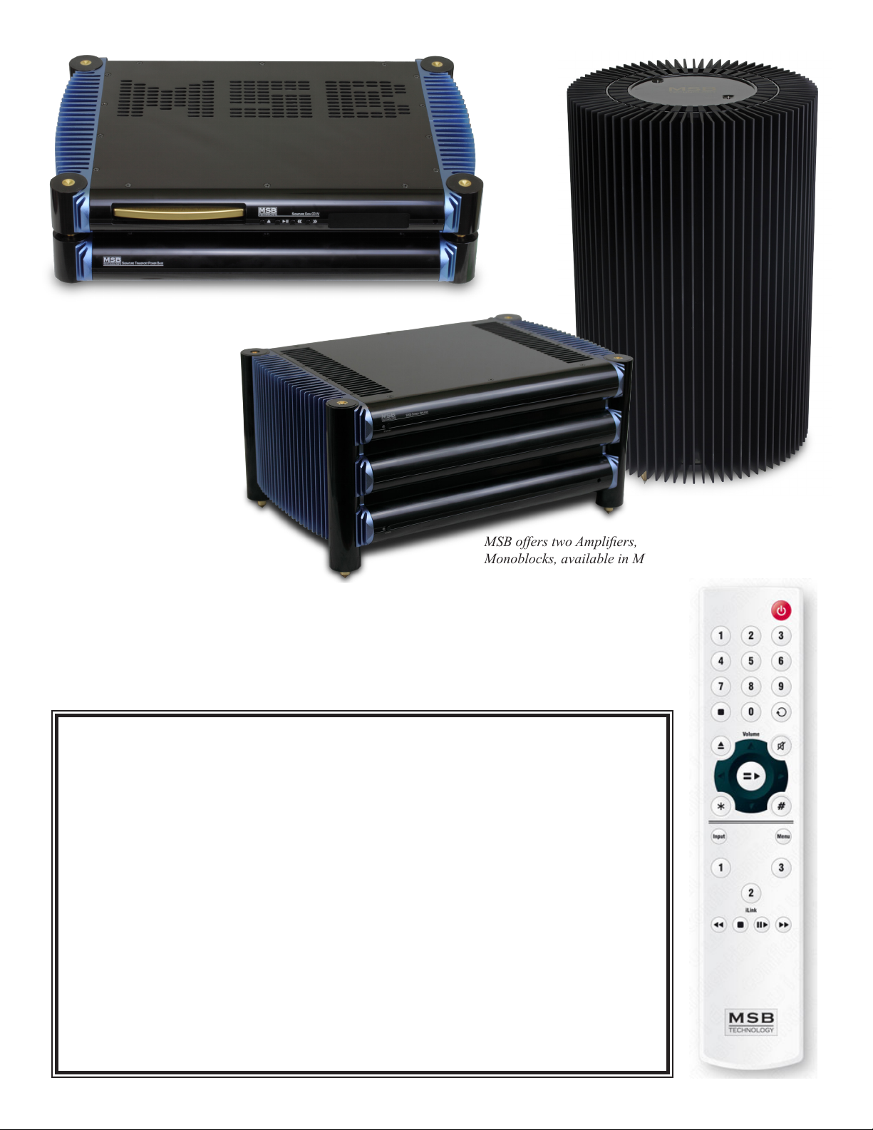
The Signature Data CD is a
great companion to the DAC
IV. It is shown here with the
Signature Transport Power
Base in Satin Black.
MSB offers two Ampliers, the Stereo S201 and the M203
Monoblocks, available in Matt White or Satin Black.
Sign Magnitude Ladder daC SpeCifiCationS
inputS: BnC, rCa, toSLink, XLr aeS/eBu, uSB2,
MSB pro i2S and BaLanCed anaLog inputS
rCa outputS: 2.62 V rMS (7 Vpp)
rCa output iMpedanCe: 53 ohMS without VoLuMe ControLS, 38 ohMS with VoLuMe ControLS
BaLanCed output: 5.23 V rMS (14 Vpp)
BaLanCed output iMpedanCe: 106 ohMS without VoLuMe ControLS, 76 ohMS with VoLuMe ControLS
VoLuMe ControL: 1/4, 1/2 or 1 dB Stepped attenuator, (78, 156 or 312 StepS)
SaMpLing frequenCy: 32 khz to 384khz
Bit depth: 32 Bit
3
Page 4
Unique Technology - the past and the future
In the 1980’s early DACs were all 16 bit ladder DACs, with a precision laser-trimmed resistor
creating the appropriate analog level for each of the bits. The DACs worked well and sounded
good. They were quite expensive as very accurate resistors were required. Then along came
the “single bit” DACs. Rather than using a resistor to create an analog level, pulse width
modulation was used. Basically each bit was created by turning a switch on and off for the
appropriate length of time. The resulting square wave pattern was ltered to create a smooth
output. The expensive resistors were gone, and so was the good performance. Next came
the Delta Sigma DAC. It used the same pulse width modulation but rather than creating a
single large pulse for each data point, the data point was created with many small pulses. This
allows the pulses to be smoothed with a less radical lter, and improves the sound. As you
can see, upsampling the input signal to a higher frequency reduces the ltering requirements
and thus improves the sound.
The DAC IV draws from the older, superior ladder technology, but with incredible
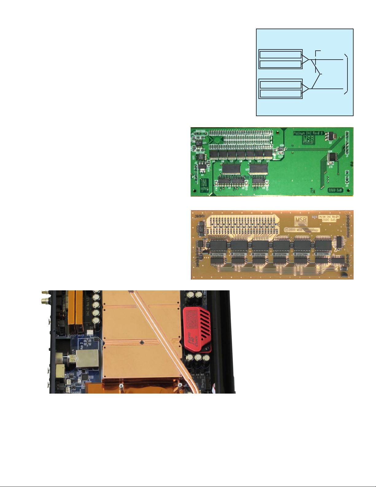
improvements. The Basic Diamond contains four 24 bit MSB DAC
modules (seen below). The Diamond is fully balanced so there is
a matched pair of 24 bit DAC modules for the inverted and noninverted signals on each of the right and left channels. Finally, each
DAC module contains one R2R ladder DAC with a 23 bit negative
sign and one R2R ladder DAC with a 23 bit positive sign. Together
this makes a true 24 bit DAC. This design allows the quieter moments
in your music to be true to the music, without the linearity errors
near zero that plague normal ladder and delta-sigma DAC designs.
With a dual 24 bits of combined resolution, a 24 bit source gives a
true 24 bit resolution without the losses and errors that make your
normal 16 or 24 bit DAC perform far less than their actual resolution
(normal 16 bit DACs only muster a meager 12 bits of resolution).
The DAC IV is carefully designed so as to require no DC correction
Second Generation Platinum DAC module - Smaller but more bits!
in the output stage. This allows direct DC coupling on the output
stage for pure, uncolored sound -- with no output ltering to muck
up your high end or smear your bass attack.
Right Channel
MSB DAC Module (Non-inverted signal)
23 bit positive sign DAC
23 bit negative sign DAC
MSB DAC Module (Inverted signal)
23 bit positive sign DAC
23 bit negative sign DAC
BLoCk diagraM
Toggle Switch
Coaxial Out
Balanced Out
Another major difference in the DAC IV is the type of output.
Essentially all ladder DACs produce a current output. This is
converted to a voltage output with a current-to-voltage converter.
This problematic circuit colors the sound and introduces nonlinearity. The DAC IV is a true voltage DAC with a voltage output
right from the source. All ampliers have slew rates greater than
1000 Volts/microsecond. The output impedance of the DAC IV is
53 ohms.
Special Features
Original Platinum DAC module
The Diamond contains four 26
bit DACs, twice the number of
steps as the Signature DAC IV.
The DAC IV has many special features. The following sections discuss these features and how they work. As MSB Technology has
developed, so has our DAC architecture. Our advanced digital lter now replaces the asynchronous upsampling of earlier models. The
32X Digital lter goes way beyond our older 16X lter and 4X upsampling. To play a 32 bit/384 kHz le the Diamond only needs to be
plugged into the MSB Data CD IV player and a DVD with a 32/384 .wav le needs to be played. The new reclocking feature dynamically
buffers and re-clocks all the data and clock signals to provide a virtually jitter-free source directly to the DACs.
4
Page 5
010010100011101000110110
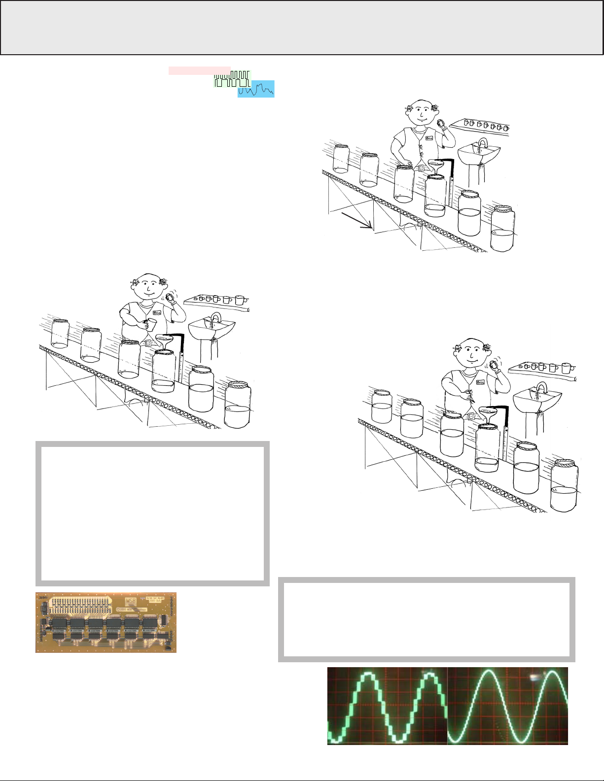
THE DAC STORY
how daCS work
A DAC is a circuit that converts
digital measures of audio amplitude
in discrete steps into a continuous analog
electrical equivalent of the sound to be reproduced. The
amplitude is a digital number (like a 16 bit word) and the
steps occur based on the sampling rate (like 48,000 times per
second). This process is very much like an endless conveyer
belt with empty one gallon jugs on it, moving by a lling
station. The size of the jug is xed, the rate they pass by is
determined by the sampling rate. The goal of the DAC is to
ll each jug to exactly the right level specied by the music.
There are three techniques used to accomplish this; Delta
Sigma, Ladder, and the MSB Sign Magnitude Ladder.
Each sample or jug is
filled to the right level
with many measuring
cups, poured to reach
the target level.
Delta Sigma DaCS (Single Bit)
A “one bit” measuring cup is either
full or empty. With 64 times over-
sampling, the cup is only 1/64th
the volume of the jug. This rather
crude cup does not
come close to
being accurate
enough. The cup
would need to be
1/16,777,216th
the volume of the jug
to be accurate.
laDDer DaC
A ladder DAC is different
in that instead of a single
measuring cup (or bit), a
whole array of cups are
available, from very
small to very large.
what aBout Jitter?
Jitter is a variation in the speed of the conveyer belt.
With a Delta Sigma DAC, the quantity of water ending
up in the jug is dramatically affected by the speed
change because the whole cycle is occupied with the
application of many small scoops of water. With either
Ladder DAC method, all the water is placed in the jug
at the same time, and even if the jug is a little ahead
or behind in the conveyer belt, the quantity is still
accurate. That is why we never heard much about jitter
until the rst Delta Sigma DACs arrived on the scene.
Any combination of cups
can be used to fill each jug
to exactly the right level.
Line speed
is like Sampling
Rate (48,000 per second)
No filtering
is required but
the accuracy is
defined by the
cumulative error of
all the cups used.
Because the jars are
typically 1/2 full when
finished, we start
with very accurately
1/2 filled containers
instead of empty ones.
From there, we again
use the wide range of
measuring cups to either add
or take away from each jar.
By keeping a running tally of the error and by going a little over
and a little under in many many samples, a very accurate average is
reached, but only with an aggressive filter applied to the output.
mSB Sign magnituDe laDDer DaC
The MSB Sign Magnitude
Ladder DAC is like a Ladder
DAC but refined in two ways.
Again each jar is filled exactly so no
filtering is needed, but because we only had to add or subtract a little bit
our accuracy is higher. Because our hearing is most sensitive to low level
sound (sound near the 1/2 full zero crossing) our DAC is most accurate
near 1/2 full where we use the smallest and most accurate measuring cups.
the MSB diaMond daC
No commercial DAC is available with the level of accuracy
we wanted without ltering, so we produce our own using
discrete logic and resistors in a DAC module. MSB is unique
in this respect. The result is a signal-to-noise rating of up to
160 db and THD+Noise ratings near the theoretical limit of
a 24 bit source.
what aBout upSaMpLing?
Synchronous Upsampling like MSB does just means adding more
jars between the existing jars and moving them faster down the line.
By looking at many jars before and after the new empty one, we
calculate how full to make it. The result is smaller steps as shown in
the waveform.
5
Page 6
Upsampling
Upsampling has been in and out of vogue for many years. Its
benet has been obvious in one DAC and nonexistent in another.
We do not do upsampling as such in the SELECT model. We have
the accuracy and precision which is compromised with upsampling.
Custom MSB Digital Filter
The DAC IV has a custom DSP based Digital lter. The sine x
function is the ideal shape to apply to the audio lter task, but
unfortunately to work perfectly it must sample an innite number
of samples. Our 16x lter contained 3200 taps, a very large sample
and worked well. The 32x Filter contains and amazing 6000 taps,
and the increased size of the lter more closely approximates the
ideal lter. Immediately you can hear the increased clarity of the
music.
MSB has applied noise shaping technology, not directly to the
audio as SACD and Delta Sigma DACs do but to the actual digital
lter. This novel approach reduces that digital harshness without
loss of detail or focus.
Just as glasses bring an image into focus for eyes that are not
perfect, we have applied a corrective algorithm to the slight
imperfections specically found in our DAC architecture. This
new innovation focuses the instruments more accurately on the
soundstage.
About the Clock / Jitter Control
Jitter control devices (and inputs on most DACs) normally reclock
the input signal in attempt to lessen the jitter of that incoming
signal. The DAC IV does no such re-clocking. We actually pay no
attention to the clock on the input signal. All internal clocks are
generated by an extremely accurate plug-in clock. Since the input
clock is no longer related to the clock of the DAC IV, an intelligent
½ second buffer is used to maintain data synchronization.
A clock header is a part of the DAC IV that will allow even more
accurate clocks to be installed as an upgrade as they become
available. Clock jitter seems to be the single biggest contributor to
digital harshness. MSB clocks are the lowest jitter audio clocks in
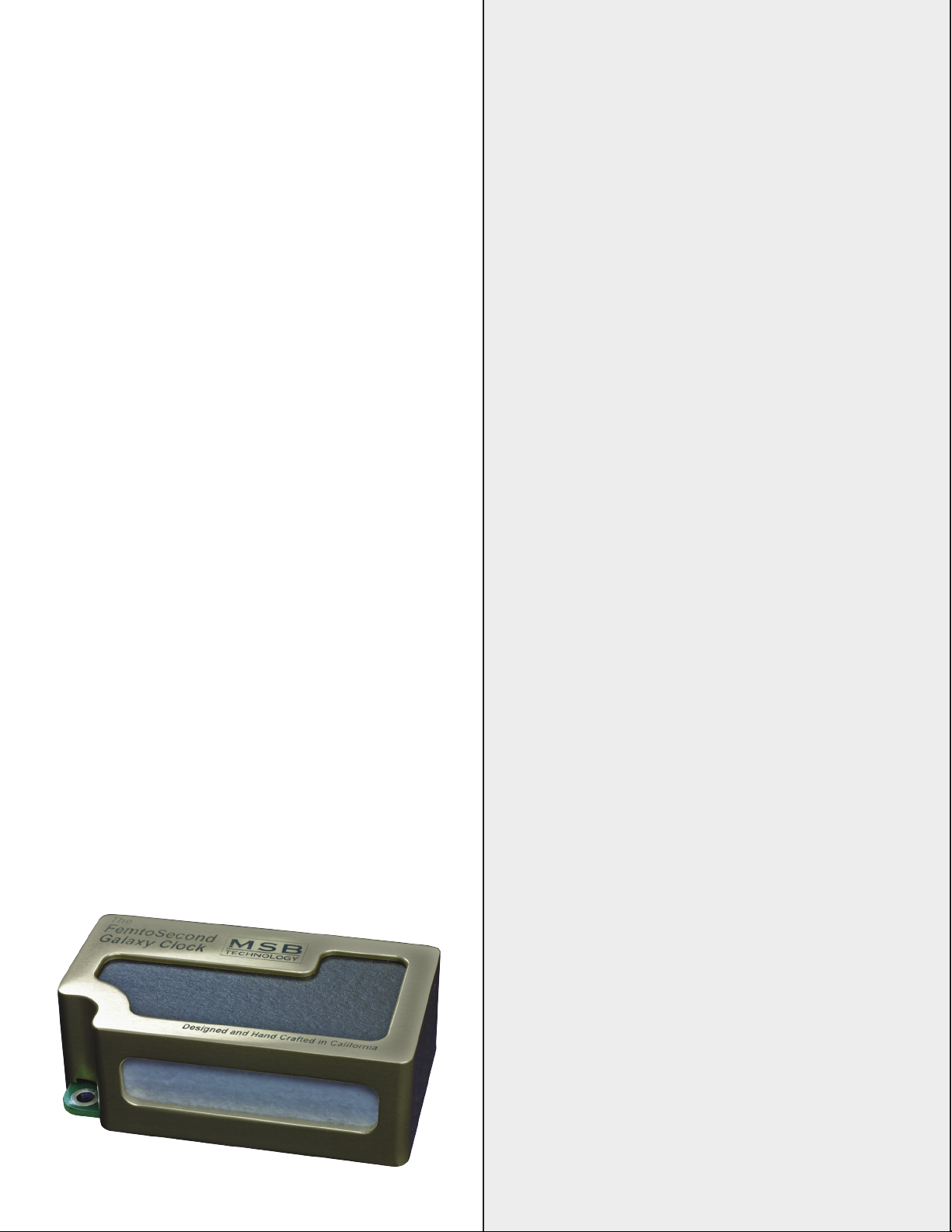
the world. The DAC IV plus models are supplied with the Femto
140 Clock with about 140 femtoseconds of jitter. The SELECT
comes standard with the Galaxy Femtosecond Clock which offers
about 77 picoseconds of jitter.
MSB Digital Filter History and Detail
One of our primary goals at MSB is to provide the music lover with the
most accurate musical experience possible. During years of careful
design and improvement of our custom discrete DACs, which form the
heart of your Diamond DAC, we realized that the Diamonds sound quality
was no longer limited by them. We next narrowed the problem to the
Digital Filter which was feeding our DACs. While the excellent Burr-Brown
(Now owned by Texas Instruments) DF1704 Digital Filter had served
us well in the past, it had became the bottleneck once we started using
our new Second Generation DAC modules. After a thorough search of
all the available off the shelf and custom DSP based Digital Filters we
realized that little improvement could be had from any of them. With no
other option in sight we decided to build our own solution.
Converting the ones and zeros of Digital Audio into music is an
enormously delicate and critical process. Each individual sample that
makes up the audio stream must be converted into the high resolution,
continuous analog voltage that can be transformed into the sound that
you hear. Any misstep can corrupt the nal result ending with audio that
does not sound anything like the original recording. Errors in translation
can make a harsh, veiled, muddy, and/or tonally colored result. Minimizing
each potential problem allows the original recording to shine through.
Audio reproduction starts when the DAC receives the binary coded
information from the source. The rst step requires recovering the audio
samples, which represent the nal output voltages, and the timing, which
tells the DAC when to output those voltages. Next the sample rate is
raised and the data is digitally ltered. While it is possible to feed the
DAC with the original audio samples thereby avoiding the use of a digital
lter skipping this step has many unintended consequences. After being
digitally ltered the digital stream is feed to the DAC. The DAC receives
the digital audio samples and converts them into a continuous analog
voltage. Our DACs instantly convert the data into a precise continuous
voltage waveform with timing determined by the DACs conversion clock.
The digital lter is necessary because mirrored image frequencies
created during the conversion process must be removed. If the DAC
did not have a digital lter, an analog lter with an aggressive response
must remove these image frequencies. These brick wall analog lters
seriously damage the signal by corrupting the original phase of the sound
and cannot fully remove the high frequency images. This results in harsh
or rolled off high frequencies and poor soundstage focus.
Traditional digital lter designs consist of cascaded FIR (Finite Impulse
Response) lters, each of which raise the sample rate by two. The
intermediate data between the lters is usually stored at less than 40
bit resolution. Since the next lter works with previously computed data
the resolution decreases with each lter pass. This limits higher quality
digital lters to a low oversampling rate (usually 8x) before the output
starts to deteriorate. The loss in resolution is typically not apparent when
using the best conventional digital lters with standard DAC chips, but in
combination with our high resolution DACs the problem is very apparent.
The sound becomes muddy, veiled and un-involving when using any
off the shelf digital lter. To counter this problem the MSB Digital Filter
does it’s ltering in one lter stage that raises the sampling rate by 32.
FIR lters operate by multiplying each sample in the data by a set of
lter coefcients and then summing the result. Most digital lters round
the result of each addition before the adding next sample. This repeated
roundoff results in a similar problem to the cascaded 2x lter approach,
muddy sound. MSBs digital lter uses bit perfect accumulation in an 80
bit accumulator completely eliminating these debilitating roundoff errors.
Only as the last step do we carefully convert the audio to the 24 or 26
bits our DACs require. The high sampling rate of the output allows us to
include advanced ultrasonic dither and noise shaping techniques in this
step to achieve greater than 24 bit effective resolution.
Through extensive listening tests we have found that the choice of lter
coefcients has a great impact on the tone of the music. We have found
that steep, phase perfect “Brick Wall” lters tend to sound the most
neutral but are also the most difcult to implement without problems.
Improvements we have made in our digital lter, with its single stage
design and 80 bit computation, allow us to use very steep lters with
no compromises.
6
Page 7
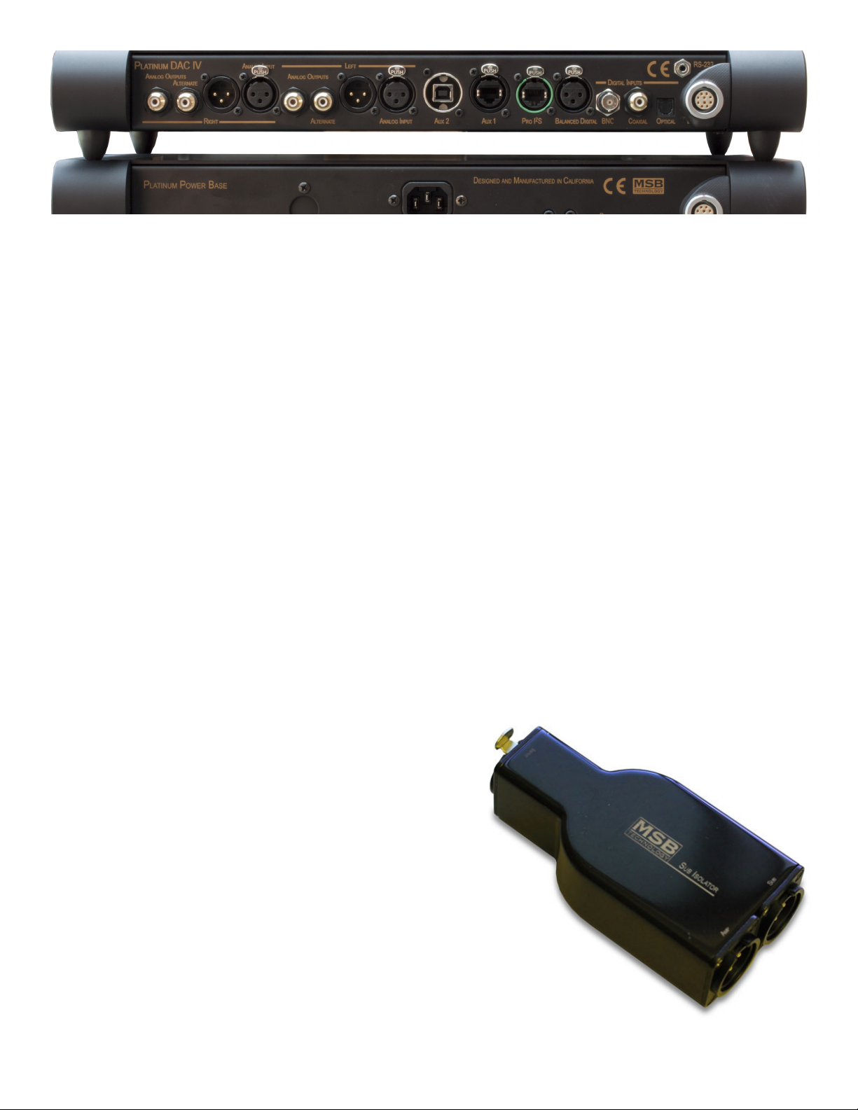
Standard Balanced Rear Panel Analog Details - (left to right)
Right Analog Single-Ended RCA Output – This is the primary single ended RCA analog output. It is a non-inverted copy of the Balanced
out with one bit less resolution than the balanced output. The output impedance is 38 ohms with volume control and output level is 7
Volts PP (2.62 V RMS).
Right Analog Single-Ended RCA Alternate Output – This is the alternative single-ended RCA analog output. It is the exact same as the
rst RCA output except inverted. When the optional Second Analog Input upgrade is installed, this becomes a single-ended analog
input. As an input, this line should be terminated or connected to a source as it is directly connected to the output when the DAC power
is turned off.
Right Analog Balanced XLR Output – This is the balanced XLR analog output. The output impedance is 106 ohms with volume control,
and output level is 14 Volts PP (5.24 V RMS).
Right Analog Balanced XLR Input – This is the balanced analog input. This input can be either volume controlled or not, depending on
the menu settings. This input is ideal for adding a vinyl input to your system. Minimum input impedance is 2 kohms. At 0 dB volume
setting, the analog inputs are a direct pass-through.
Left Analog Connections – Same as right above.
Aux One and Two – A second balanced analog input can be installed here, instead of the single-ended option. It can use or bypass the
volume control independently of the rst analog input. (These are normally used for the USB input and any extra digital input)
Single-Ended Configuration Rear Panel Analog Details - (left to right)
Right Analog Single-Ended RCA Output – This is the primary single ended RCA analog output. It is an optimized output with the same
resolution as the balanced output. The output impedance is 38 ohms with volume control and output level is 7 Volts PP (2.62 V RMS).
Right Analog Single-Ended RCA Alternate Output – This is the same output again.
Right Analog Balanced XLR Output – None.
Right Analog RCA Input – This is the RCA analog input. This input can be
either volume controlled or not, depending on the menu settings. This input is
ideal for adding a vinyl input to your system. Minimum input impedance is 2
kohms. At 0 dB volume setting, the analog inputs are a direct pass-through.
Right 2nd Analog RCA Input – When the optional Second Analog Input
upgrade is installed, a second single-ended analog input is added. As an
input, this line should be terminated or connected to a source as it is directly
connected to the output when the DAC power is turned off.
Left Analog Connections – Same as right above.
How to Hook Up a Subwoofer
Main AMP Balanced – Use the main single-ended output for Subwoofer.
(Preferred Conguration)
Main AMP Single-ended – Use the alternate single-ended output to connect
to the Subwoofer.
If the subwoofer is powered, we would strongly recommend using our SUB
ISOLATOR product to protect the DAC from interference. It makes a huge
difference. Powered Subs almost always use switching power supplies or
Class D amps which feed high-frequency noise back up the analog input
to the DAC.
The SUB Isolator does a great job of isolating your DAC
from Subwoofer power supply noise.
7
Page 8
Rear Panel Digital Details - (right
to left)
Power Input – This product must be plugged into
a DAC IV SELECT Power Base. It will not work
with any previous MSB power supplies.
RS-232 – The RS-232 input is used for controlling
the DAC or volume control using a remote system.
The complete table of commands can be found
under the support tab of our web site.
Toslink – Although this format has the lowest
bandwidth, it is one of the more common outputs
on low-end products. It also offers ground
isolation between products and noise immunity
over long runs. It is unlikely to work at sample
rates over 192 kHz.
Coaxial – A good input for short runs and lower
frequencies. Limited to 384 kHz, 24 bit data.
BNC – Same as Coaxial but with a BNC connector.
Another digital input.
Balanced digital – The AES/EBU Professional
input is the preferred standard input. The
balanced nature of this input allows great cable
lengths as well as total noise immunity. Limited
to 384 kHz, 24 bit data.
MSB PRO I2S – The MSB PRO I2S uses CAT-6
cabling. It provides an input for use with other
MSB products. It can handle data up to 384 kHz
and 32 bits. This interface also outputs the clock
to keep the transport in sync.
The MSB PRO I2S Network
One of the most powerful features of MSB products is the PRO I2S network. Most
new MSB products have a PRO I2S connection available. The MSB PRO I2S has the
following capability:
• Works with standard UN-SHIELDED CAT6 cable
• Simultaneous transmission of 8 audio channels with 32 bit resolution at 384 kHz
sampling rate.
• MSB CAN Interbox communication Bus (for communications between
boxes)
• Low Jitter master clock distribution from the DAC back to the Transport.
This network is our answer to 384 kHz audio transmission and multichannel transmission
in the same package. We provide network
outputs on our own transports and offer
a source upgrade to your transport as
well. With multichannel sources, up to
8 channels of decoded data can be
sent through one wire to separate
DACs. CAT6 wire is very convenient
as it has become the standard for
all computer networks. Several
cables are available for connecting
MSB transports to the Diamond Line
including CAT6 cable at any length
up to 80 feet.
MSB Signature USB2 – This USB input is installed in one of the AUX positions so that as USB changes, it will be easy to upgrade the
input. It can handle data up to 384 kHz and 24 bits. It requires computer power so please use standard USB cables. See the box below
for setup. For more detailed and up-to-date information check our web site.
Aux 1 and 2 – These are all purpose expansion slots. They can be congured as a USB input, MSB PRO I2S Input, MSB Network or extra
XLR or RCA digital inputs. It can also become a second analog input. They will also accommodate anything new that comes along.
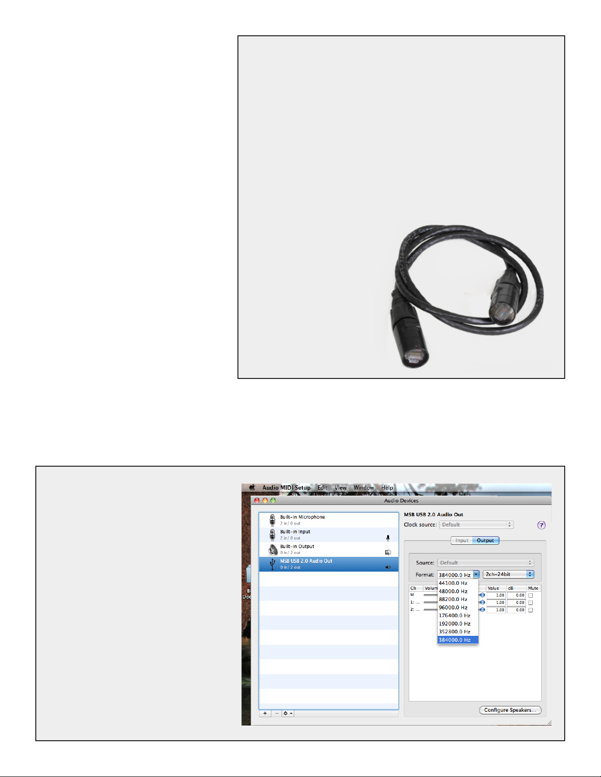
Apple MAC OS - USB Setup
On the MAC the USB is plug and play. The MAC
will recognize the USB DAC and its capabilities
and will allow the output to be set to any sample
rate desired. The bad news is, with certain
programs such as iTunes, the output sample rate
has to be set manually when the le sample rate
changes. So if you set the output for 192 kHz, and
played a 192 kHz le, it would play perfectly, but
if you then played a 44.1 kHz CD, the MAC OS
would upsample that le to 192 kHz. Computer
upsampling is not too bad, but does not compare
at all with the quality of the upsampling done by
MSB. Better to change the output to 44.1 kHz
and play the le bit-perfect. Fortunately there is
an APP called BIT PERFECT. Download it and
the MAC with the MSB USB 2 is perfection itself.
The Apple Audio MIDI Setup screen is shown
above. Notice that the presence of the MSB USB
Signature DAC has allowed 352.8 and 384 kHz
sample rates to show up on the menu. Normally
they are not present. iTunes will play at whatever
sample rate you select in this setup.
8
Page 9
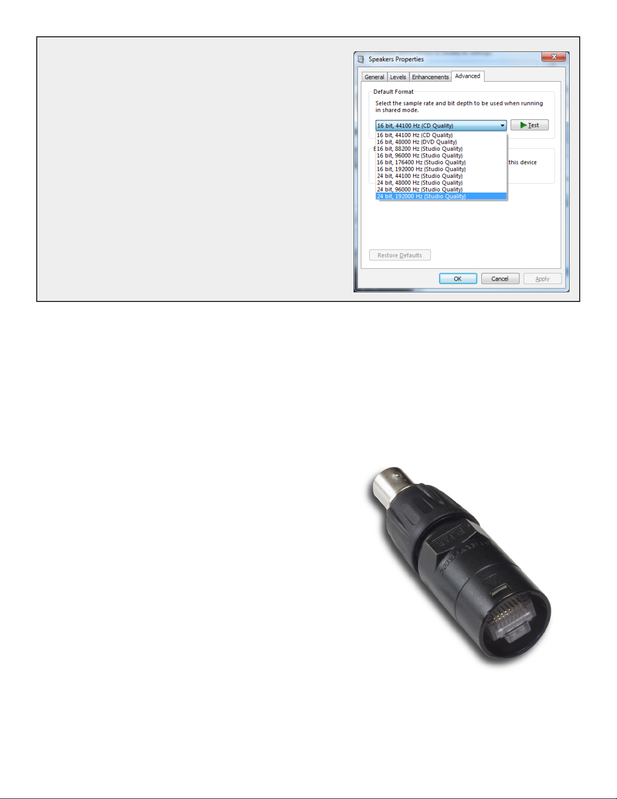
Windows OS - USB Setup
The amazing thing about the MSB USB 2 input with Windows is that
once you get it set up it works completely and absolutely perfectly,
with every le playing bit-perfect at its native sample rate up to 384
kHz with no user intervention. Just pick the song and play. The rest is
automatic and works perfectly. This is a rst for any Windows machine
I have seen and a dream come true. The bad is that MSB drivers will
have to be installed, and your music must be played with a properly set
up player program like Foobar. Its a small price to pay for perfection,
and MSB will help walk you through the process.
First, install the supplied MSB drivers from the included USB 2 drivers
CD or from our website. So with a PC, there are two possible play
modes. The “advanced speaker properties” window lets you set up
Windows output sample rates up to 192k as shown to the right. Any
audio played by an audio program would be output at this sample rate.
Specialty programs like Foobar can be modied with a plug-in, like
ASIO (http://www.foobar2000.org/components/view/foo_out_asio)
which allows Foobar to interact directly with the MSB DAC to play
every music le at its native sample rate bit-perfect. Foobar over-rides
all windows settings and is quite amazing.
Clock Interface
After years of experimenting with inputting and outputting clocks we now strongly recommend not doing this. A low jitter clock must be
physically close to the DACs. There is no lower jitter clock than the MSB clocks, and even if there were, once the clock was transmitted
from an external box so much jitter would be introduced in the cable that the clock would be marginal at best. So we are condent that
no benet would be gained from an external clock.
A different set of problems exist with outputting clocks. A paradox is created as a source needs a clock to transmit data, but when the
DAC sees the data, which can be at any sample rate, it adjusts the clock to match. Most sources cannot handle its clock adjusted on
the y. The MSB Transports can handle this as the PRO I2S interface is smart and negotiates the proper clock to be sent back to the
transport. But as new sources have this ability, and you need to access this
clock, it can be done.
The MSB CLOCK ADAPTER allows the DACs master clock to be output.
The BNC output is a LVDS level 512x master clock output that can be used
to keep a server in sync. This is a great upgrade and has already been approved by Aurender.
Clock Frequencies - The clock output frequencies are as follows:
· 44.1, 88.2 or 176.4 kHz sampling frequency source outputs a clock frequency
of 22.5792 MHz
· 48, 96 or 192 kHz sampling frequency source outputs a clock frequency of
24.576 MHz.
The Clock adapter allows the DAC clock to be
sent to your server or transport so the system
stays in sync.
9
Page 10
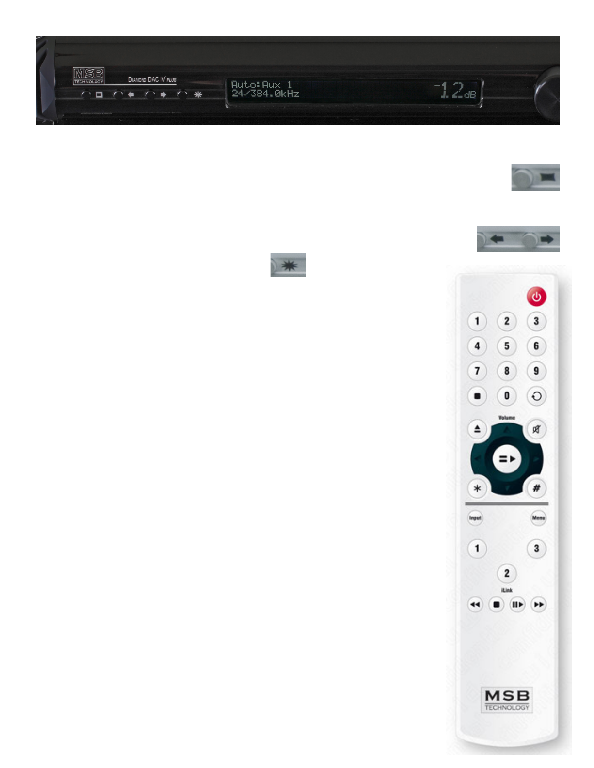
Front Panel Controls
Although the user interface is very simple and easy to use, in depth menus allow complete control of the DAC.
Menu Button – The square button is single purpose. It will enter the setup mode at the top of the menu tree. If in the setup,
and it doesn’t matter where, this button will exit the setup and return to the normal operational mode.
Input Selection – Each of the six inputs can be selected manually, or the auto mode can be selected. The auto mode is an automatic priority
switching with auto signal detection. The right and left arrows switch inputs. If the AUTO input is selected, the unit will automatically
switch inputs based on a priority (from left to right - Analog = lowest priority, MSB 2 = highest priority). When a source with a higher
priority becomes active, the unit will automatically switch to the new higher priority input. Toggling through
the inputs manually will defeat any auto switching. When in the setup menu the arrows move right and left
through the menu structure.
Star Button - The star button is used to do phase invert.
Input/Volume Knob - The large knob will select between inputs if the volume control option is not installed.
The right and left arrow buttons on the front of the unit will also switch between inputs. When the
volume control module is installed, the knob becomes the volume control. This knob adjusts the volume
between +9 dB and -69 dB. Our 0 dB actually equates to a 2.62 V rms output, just a little high in
relation to the industry standard 2 Vrms level.
Display - The display shows the Input in the upper left. The lower left shows the input sample rate and
bit depth. The right shows the volume.
Remote
The MSB remote can be used to operate several MSB products. The top half is primary for the transport.
The center is for the DAC and the lower part for the iLink.
Power – The power button turns on and off the Power Base when the optional front controls have been installed. If
your Diamond Power Base does not have a switch on the front, this button will do nothing. When the power base
is linked to the Ampliers and any other MSB products, this button will turn off the entire system. (see power base
manual for details)
Data CD IV controls – . The keypad, stop and repeat buttons are for the DATA CD IV transport and have no effect
on the DAC IV.
Volume up and down – The center block of the remote has several functions. The volume up and down buttons change
the system remote if the optional volume controls are installed in the DAC. Steps sizes are shown on the DAC
display. The mute button instantly mutes the audio if the volume option is installed.
< > = * and # buttons – These central buttons are also for controlling the DATA CD IV transport, but also can be
used for navigation of the DAC IV menus. See MENU below.
Input – This button toggles directly through the inputs of the DAC IV even if the DAC is set to the auto mode.
Menu – This is equivalent to pressing the menu button on the front panel and puts the DAC IV into the menu/setup
mode. The menus can be navigated from the front panel or using the < >, volume up/down buttons on the remote
as left, right, up and down.
1, 2, 3 – These are SELECT dened buttons set as follows:
1. Phase Invert - Toggles phase invert on and off.
2. Video Mode - Toggles reclocking on and off. This is especially useful for watching movies, where
reclocking may cause an objectionable audio delay.
3. Display On/Off - Toggles the display on and off.
Batteries – The remote control requires two CR2025 Lithium batteries.
10
Page 11

Operational Menu Options
The high level menu options have to do with operation settings. They are things that you may want to change on the y as you listen to
different music or with different equipment. See the Menu tree for details.
Phase Invert - Toggling the Phase Invert will change the absolute phase of the output. There are some recordings that “accidentally”
swap the phase. For those who are phase sensitive, we always include this option. The phase of the outputs is inverted digitally.
User Button - Denes the function associated with the user button * on the front panel.
Remote User Buttons - Denes the function associated with the remote user button 1, 2 and 3 on the remote control.
About - Displays information about the unit including the version number, serial number, distributor, and year of manufacture.
Setup Menu Options
The second level menu options have to do with setup parameter - things you will only need to set once. In most cases you will not need
to change any of these settings. See the Menu tree for details.
Video Mode - This very important feature of the DAC allow all jitter to be removed from the input source. Data is read into a memory
and then independently read out using a ultra stable clock. When enabled this option will completely replace the incoming clock with
an ultra low jitter internal clock. The DSP monitors the incoming sample frequency and detects standard sample rate signals, 44.1 kHz,
48 kHz, 88.2 kHz, 96 kHz, 176.4 kHz, 192 kHz, 352.8 kHz and 384 kHz. The on-board clock then completely replaces the incoming
clock. Other sampling frequencies use the incoming clock from the source. The DSP allocates a huge internal FIFO buffer (1/2 second
at 44.1) that stores the incoming audio to decouple the incoming and outgoing data streams. Long absolute digital silences in the music
stream, such as between tracks and during pauses, are selectively shortened or lengthened by the DSP to maintain data synchronization.
This results in a signicant delay between the audio source and the analog audio. You will not normally notice this delay unless video is
synchronized to the audio. For this reason this feature may want to be turned off when watching video, or the video should be delayed.
While using the on-board clock some very long musical performances greater than one hour with no silences, pauses or track skips
may cause a buffer overow when using a standard transport. This will sound like a small CD skip. You will probably never encounter
this case but if you do MSB can install a special ultra high accuracy clock in your transport or other audio source to totally eliminate
this possibility.
Display Brightness - Adjustable from 1 to 15.
Display on/off - When turned off, the display pops on for a bit any time anything is adjusted, then turns off again.
Restore Settings - Puts settings back to factory default setting.
Startup Volume - This is the volume setting that is set upon power up.
Maximum Volume - This is the maximum volume setting that can be reached. Use this feature to protect your speakers.
Fine Volume Steps - The Select volume modules allow half or quarter db steps to be inserted between the standard 1 db steps. In most
cases this level of resolution is not audible.
Input Setups
Analog Input Volume Control - The analog input can either be volume controlled or bypass the volume control.
Alternate Analog Input Volume Control - The alternate analog input can either be volume controlled or bypass the volume control if this
option is installed.
Switching Mode - When the input selector is manually selected, either all inputs are available or just active inputs. With active inputs
selected, A/B testing is very quick and easy.
MSB Network Channel Select - The MSB Network supports 4 stereo channels of audio. With this feature the DAC can be congured to
decode any of the 4 sets.
11
Page 12
Phase
Invert
Video
Mode
Display
Brightness
Dislay
On/Off
Startup
Volume
Maximum
Volume
Fine
Volume
Analog
Ground
Input
Setup
Restore
Settings
Off
On
Audio
Video
1-15
On
Auto Off
0 to -69 dB
No Limit
-30 to +6dB
Standard
0.5 dB Steps
Cancel
Restore?
Analog
Input
Analog In
1 Volume
Analog In
2 Volume
DSD
Decode
MSB
Clock
Switching
Mode
Network
Channel
RS232
Disabled
Enabled
Controlled
Bypassed
Controlled
Bypassed
On
Off
Off
Input
All Inputs
Active Inputs
Channel 1-4
On
Off
About
Displays
information
about DAC
Connected
Lifted
0.25 dB Steps
Output
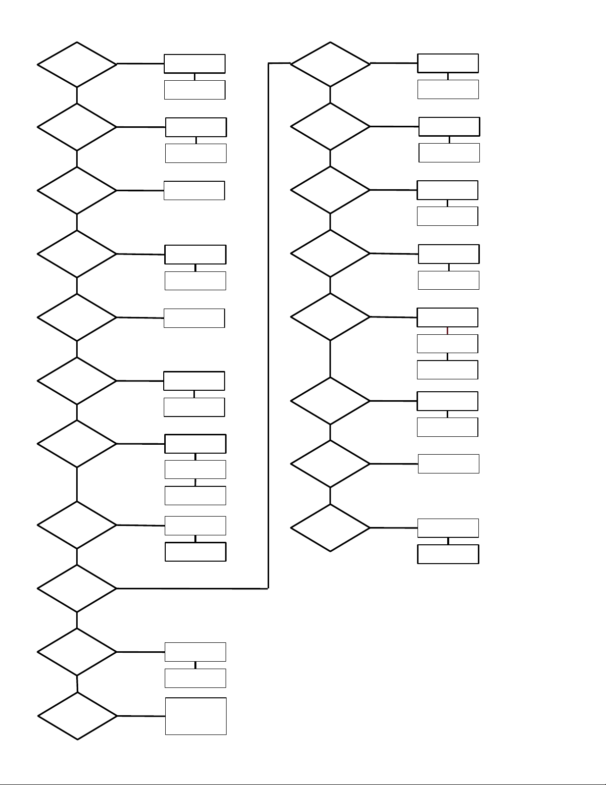
DAC IV SELECT Menu Tree
Top level menus are for operational controls. Setup menus are in the
second column.
• Press the menu button on either the front panel or remote.
• Navigate up and down the options with the front panel knob or the
volume up down buttons on the remote.
• Use the arrow buttons to navigate right and left in the menus on either
the front panel or remote.
• Use the * button on the front panel or the > button on the remote to
select.
The default settings are shown on the chart in a bold box.
12
Page 13

Upgrades and Modifications
Removal of the cover - Unplug the AC power. Work on a clean surface. Start by removing the 14 screws of the cover. Carefully remove and set
aside the cover.
Removal or Installation of the volume modules - The volume modules can be plugged in, or unplugged from the Diamond mother board. They
are held in place with their two connectors. The boards are automatically detected, so when unplugged the DAC will output the same level signal as it
would with them plugged in at 0 dB. The volume knob will now select the input and the remote volume buttons will have no effect.
Other Upgrades - Check the instructions supplied with the upgrade.
PRO input Upgrade
This upgrade adds one or two additional MSB inputs in the AUX IN positions of the DAC IV. It is a exible board so please be careful
to check the instructions carefully when installing. The upgrade offers two possible inputs:
Input #1 - Ground Isolated MSB Network
This is an improved version of the classic MSB Network. It will work with all existing MSB Network outputs on all current and older
products. This input is designed specially as the best possible input for the MSB Universal Media Transport. It has the performance of
the stock MSB Network without the coupling of ground noise. With this input both our transports can have optimal inputs. It will work
with the following:
• Data CD IV
• Universal Media Transport
• all older MSB products
Input #2 - MSB PRO I2S
The MSB PRO I2S is new and will offer amazing performance on new transports as they are brought to market. It is lower jitter and
higher speed (ready for 768 kHz music) than the MSB Network. It contains 20 channels of audio of 768 kHz, 32 bit audio in the I2S
format, as well as a an outgoing clock and control data. These can be used to send multichannel data as would be required with digital
crossovers, distribute independent super precision clocks and do auto setup of DAC parameters. Future upgrades and products will allow
MSB products to take full advantage of these new capabilities. There is an PRO I2S output on our Studio 384 kHz, 32 bit ADC and this
output will become the standard output on all new agship MSB transports. So this input works with:
• MSB Pro Analog-to-digital Converter
• Signature Data CD
• Universal Media Transport PLUS and Signature Universal Media Transport, and all new products to come
The MSB PRO Input board upgrade not only gives you the improved MSB Network input you can use today, but also gives you a PRO
I2S input that will be available for new MSB products in the future. The PRO upgrade can easily be congured for either type input.
Operation
These new inputs are added to the existing input LIST on the DAC and are selected just like the standard inputs. Please note that the
MSB Network and the PRO I2S are independent. Network sources will only work with Network inputs, and PRO I2S sources will only
work with PRO I2S inputs. So for today, the PRO board is congured for use with the PRO I2S. As PRO I2S sources are developed by
MSB, you will have an input to make use of them.
Installation
The Pro Input board plugs right in the input upgrade slot in the DAC IV. The Network connector installs in one of the AUX input holes.
Quality Check
Each SELECT is comprehensively tested. After
careful measurements and a nice burn-in period, we
do critical listening to each DAC in our reference
system.
13
Page 14

Using the DAC IV to test your source
The DAC IV is unique in that gives you a precise read out of both the sample frequency and bit depth of the incoming signal as well as
performing a test for bit perfect playback. If you are playing a CD, a copy of a CD or a ripped CD le on your computer the display should
read 44.1 kHz, 16 bit. Any other output means you are not reading the le bit-perfect and your sound quality will be compromised. This
corruption could be accidental. You may have ripped a CD with a program that does a conversion. This is very bad and you should not
do this. You may have an upsampling transport or have upsampled with software upsampling in your computer. This is also very bad.
Nobody can do as well as we can if we are given the bit perfect original. Turn off the feature and give us the real thing. You will not be
disappointed. For more detailed testing of your source, please refer to the BIT PERFECT SOURCE TESTING section of this manual.
MSB provides test les that the DAC is programmed to recognize and check for bit perfect playback.
Bit-Perfect Source Testing
Perhaps one of the most useful features of the software is the bit-perfect test. The following series of les can be downloaded from the
MSB web site:
16 bit x 44.1 kHz sample rate le (CD standard). 24 bit x 44.1 kHz sample rate le.
16 bit x 48 kHz sample rate le. 24 bit x 48 kHz sample rate le.
16 bit x 88.2 kHz sample rate le. 24 bit x 88.2 kHz sample rate le.
16 bit x 96 kHz sample rate le. 24 bit x 96 kHz sample rate le.
16 bit x 176.4 kHz sample rate le. 24 bit x 176.4 kHz sample rate le.
16 bit x 192 kHz sample rate le. 24 bit x 192 kHz sample rate le.
They are .wav test les that when played, will be identied by the DAC IV and checked, and will be reported on the display if they are
bit-perfect. If there is a problem with the test, it will play but the display will not indicate any change. Be sure upsampling is turned off in
any transport as this prevents a le from remaining bit-perfect. This system will allow you to easily test your source, especially computer
sources to see if all your settings are correct. There are les at all sample rates for both 16 bit and 24 bit operation. The 16 bit 44.1 test
le can be burned to a CD to test transports.
Troubleshooting
No Input Frequency indicated on Display (reads “No Signal”) - This means no input is detected. Check input select. Change to auto mode to be
sure. Check for bad cable, or cable plugged into the wrong output on the transport.
No Input Bit Depth indicated on Display (reads “0 bits”) - This means an input is detected but the music is not playing. Check the source to be sure
it is playing.
No sound but Display indicates frequency and bit depth - Check that power cable is plugged in all the way. You may have digital power but no
analog power. Check that source is valid audio source. Change to a standard CD just to be sure. Check that analog outputs are connected properly.
Check that volume is turned up.
Still no sound - connect an analog output from the source directly to the preamp input. Verify that the rest of the system is working. Now move the
same analog cable to the DAC and plug in the analog source to the analog inputs. Verify the DAC pass-through is working. Now plug in a digital
source. You should hear a click and the front display should indicate frequency.
Frequency readout is off - The Diamond shows the actual input frequency. Check your source settings.
High sample rate source indicates 48 kHz on front panel - Check setup menu of source. Many products downmix to 48 k.
DVD-A source does not indicates 192k - DVD-A players must be upgraded to provide a true 192K output. Production players downmix to 48K. Many
DVD-A disks are produced in 44.1, 48 and 96 k as well.
DC on output when power is off - If the second Analog input option has been installed, the output is connected to the 2nd input when the power is
turned off. Terminate the input when not used to avoid an open input to the AMP.
USB input not working right - Check your computer settings. This is much harder than you would think. With many operating systems you may
need to make small changes to the instructions. As ALWAYS with everything computer - Restart. Power off the computer and DAC and start over if
anything is acting strange. Second thing is to change your USB cable. Audiophile USB cables rarely work at high sample rates. Try a cheap printer cable.
PRO Input is not working - Make sure you are not mixing a PRO I2S input and a MSB Network input. They are not compatible and will not work.
Make sure you have the latest rmware.
Analog Input not selectable - This input defaults OFF. Go into the menus and turn on the Analog Input.
Warranty
The SELECT carries a ten year original owner warranty in the country of origin. No returns accepted without an RMA. All units must be returned to the
distributor in the country of origin. You must be the registered owner. The DAC displays the country in the “about” tab of the menu. The power base
has the distributor and country printed on the box. MSB will not make warranty repairs on grey market products. Be sure the product you purchased is
authorized to be in your country. Upon receipt, MSB will repair or replace any defective product. All product shipped FOB Watsonville, CA. Shipping
and shipping damage is the responsibility of the consignee.
14
Page 15

Warranty
Registration
The following information must be sent to MSB to register your
product:
Name:______________________________________
Dealer:_____________________________________
Country: ___________________________________
Purchase Date:_______________
Model Number: DS __________
Email Address: ____________________
(so we can inform you of upgrades)
I certify that I am the original owner of this SELECT
Signature: ________________________________
Please send this information to us by the easiest way.
Take a picture or scan and email to: [email protected]
Fax to: 831-662-3800
Mail to:
MSB Technology Corporation
625 Main Street
Watsonville, CA 95076
15
 Loading...