

Page 1
GARD
GARD
(APOGEE P1) Gas Sensors
™
S
S & DS
Instruction Manual
WARNING
THIS MANUAL MUST BE CAREFULLY READ BY ALL INDIVIDUALS WHO HAVE OR WILL HAVE
THE RESPONSIBILITY FOR INSTALLING, USING OR SERVICING THIS PRODUCT. Like any piece
of complex equipment, this product will perform as designed only if installed, used and serviced in
accordance with the manufacturer’s instructions. OTHERWISE, IT COULD FAIL TO PERFORM AS
DESIGNED AND PERSONS WHO RELY ON THIS PRODUCT FOR THEIR SAFETY COULD
SUSTAIN SEVERE PERSONAL INJURY OR DEATH.
The warranties made by Mine Safety Appliances Company with respect to these Products are voided if the
products are not installed, used and serviced in accordance with the instructions in this user guide. Please
protect yourself and others by following them. We encourage our customers to write or call regarding this
equipment prior to use or for any additional information relative to use or repair.
Instrument Division 1-800-MSA-INST or FAX (412) 776-9783
MSA International (412) 967-3228 or FAX (412) 967-3373
In Canada 1-800-267-0672 or FAX (416) 620-4225
© Mine Safety Appliances Company 2006 - All Rights Reserved
MINE SAFETY APPLIANCES COMPANY
PITTSBURGH, PENNSYLVANIA 15230
(
L) REV 1.1 February 2006 10070975
Page 2

MSA
Permanent Instrument Warranty
1. Warranty- Seller warrants that this product
will be free from mechanical defect or faulty
workmanship for a period of eighteen (18)
months from date of shipment or one (1) year
from installation, whichever occurs first,
provided it is maintained and used in
accordance with Seller’s instructions and/or
recommendations. This warranty does not
apply to expendable or consumable parts
whose normal life expectancy is less than one
(1) year such as, but not limited to, nonrechargeable batteries, filament units, filter,
lamps, fuses etc. The Seller shall be released
from all obligations under this warranty in the
event repairs or modifications are made by
persons other than its own or authorized
service personnel or if the warranty claim
results from physical abuse or misuse of the
product. No agent, employee or representative
of the Seller has any authority to bind the
Seller to any affirmation, representation or
warranty concerning the product. Seller makes
no warranty concerning components or
accessories not manufactured by the Seller,
but will pass on to the Purchaser all warranties
of manufacturers of such components. THIS
WARRANTY IS IN LIEU OF ALL OTHER
WARRANTIES, EXPRESSED, IMPLIED OR
STATUTORY, AND IS STRICTLY LIMITED
TO THE TERMS HEREOF. SELLER
SPECIFICALLY DISCLAIMS ANY
WARRANTY OF MERCHANTABILITY OR OF
FITNESS FOR A PARTICULAR PURPOSE.
2. Exclusive Remedy- It is expressly agreed
that Purchaser’s sole and exclusive remedy for
breach of the above warranty, for any tortious
conduct of Seller, or for any other cause of
action, shall be the repair and/or replacement
at Seller’s option, of any equipment or parts
thereof, which after examination by Seller is
proven to be defective. Replacement
equipment and/or parts will be provided at no
cost to Purchaser, F.O.B. Seller’s Plant.
Failure of Seller to successfully repair any
nonconforming product shall not cause the
remedy established hereby to fail of its
essential purpose.
3. Exclusion of Consequential Damage-
Purchaser specifically understands and agrees
that under no circumstances will seller be liable
to purchaser for economic, special, incidental
or consequential damages or losses of any
kind whatsoever, including but not limited to,
loss of anticipated profits and any other loss
caused by reason of non operation of the
goods. This exclusion is applicable to claims
for breach of warranty, tortuous conduct or any
other cause of action against seller.
Page 3

General Warnings
WARNING
1. The ZGARD S & DS APOGEE P1
gas sensors described in this
manual must be installed, operated,
and maintained in strict accordance
with the labels, cautions, warnings,
instructions, and within the
limitations stated.
2. The ZGARD S & DS APOGEE P1
gas sensors must not be installed in
outdoor areas or in locations where
explosive concentrations of
combustible gases or vapors might
occur in the atmosphere: Class 1,
Group A, B, C, and D areas as
defined by the NEC. Because the
gas sensors are not explosionproof, they must be located in nonhazardous areas.
3. Do not paint the ZGARD S & DS
APOGEE P1 gas sensors.
4. The only absolute method to assure
the proper overall operation of a
gas detection instrument is to check
it with a known concentration of the
gas for which it has been calibrated.
Consequently, a calibration check
must be included as part of the
installation and as a routine
inspection of the system.
5. Use only genuine MSA replacement
parts when performing any
maintenance procedures provided
in this manual. Failure to do so may
seriously impair instrument
performance. Repair or alteration of
the ZGARD S & DS APOGEE P1
gas sensors, beyond the scope of
these maintenance instructions or
by anyone other than authorized
MSA service personnel, could
cause the product to fail to perform
as designed, and persons who rely
on this product for their safety could
sustain serious personal injury or
death.
6. The ZGARD S & DS APOGEE P1
gas sensors must be installed,
located and operated in accordance
to all applicable codes. These
codes include, but are not limited to,
the National Fire Prevention Code
and National Electric Code.
7. Do not exceed the relay contact
ratings listed in this manual.
Otherwise, the relay operation may
fail, which can result in personal
injury or death.
Failure to comply with the above warnings
can result in serious personal injury or
death.
Page 4

Table of Contents
Section 1 General Information and Applications 1.0
Section 2 Installation Guidelines
Section 3 Operating Specifications and Features
Section 4 (SS) Sensor; Operating Features and Setup, Sensor Address Binary Code Table, Output Test and Cut-off
Section 5 (EC) Sensor; Operating Features and Setup, Sensor Address Binary Code Table, Output Test and Cut-off
Section 6 Table 1 Sensor Address Binary Codes
Section 7 Carbon Monoxide Solid-State (SS) Sensor, Calibration
Section 8 Carbon Monoxide Electrochemical (EC) Sensor, Calibration
Section 9 Nitrogen Dioxide Electrochemical (EC) Sensor, Calibration
Section 10 Sensor Start-Up Procedure
Section 11 Parts List
Drawings
107127 CO (SS) Solid-State, APOGEE P1 Output Sensor Circuit Board Layout
107128 CO and NO2 (EC) Electrochemical, APOGEE P1 Output Sensor Circuit Board Layout
107129 (SS) Solid-Sate, Sensors Calibration Gas (Humidified) Setup Procedure
107130 Installation Outline, ZGard S, APOGEE P1 Gas Sensors
107139 Installation Outline, ZGard DS, APOGEE P1 Dual Gas Sensors
2.0
3.0
4.0
5.0
6.0
7.0
8.0
9.0
10.0
11.0
Page 5
Section 1
ZGARD S & DS APOGEE P1 Gas Sensors
General Information and Applications
The ZGARD S APOGEE P1 sensors are designed to detect the presence of Carbon Monoxide or Nitrogen Dioxide in air.
The EC type employs electrochemical plug-in cells. The solid-state (SS) type employs Metal Oxide Semiconductor (MOS)
sensing technology. Each sensor generates a representative output signal proportional to the calibrated operating range.
The ZGARD DS APOGEE P1 is a Dual Sensor in one enclosure and both sensors employ Electrochemical (EC) plug-in
cells. The sensor is designed to detect the presence of Carbon Monoxide and Nitrogen Dioxide in air.
The ZGARD S & DS APOGEE P1 sensors are specifically designed for the Siemens network communication protocol.
These sensors are integrated with the Siemens equipment and the associated Building Environmental Automation Systems.
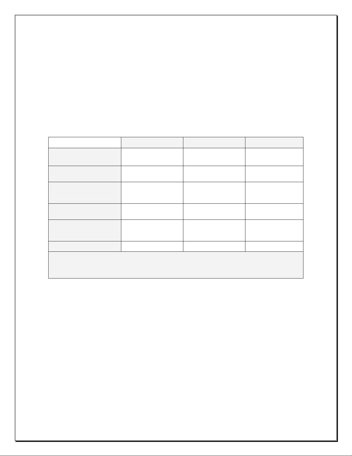
The table below provides the distinctive features of the ZGARD S APOGEE P1 Sensors. This is a quick
guide for determining the operating features of each sensor.
The performance of any ZGARD S & DS APOGEE PI sensors are dependent on the appropriate and
strategic placement within a guarded area.
ZGARD S & DS APOGEE P1
SENSORS
Principal of Operation
Operating Range
On-Board Test
Digital Output
Calibration
Cut-Off Feature 17ppm NONE NONE
Periodic inspections and calibration: This unit requires calibration. The calibration frequency will be a function of the
operating conditions, including operating under extreme temperatures, exposure to contaminants or gas concentrations
greater than the lower explosive limits. A calibration inspection must be included as part of a routine maintenance to
ensure proper operation of the gas detection unit. If unit span or zero cannot be adjusted, the sensor may be approaching
its end-of-life or has been contaminated and must be replaced.
CARBON MONOXIDE
(SS)
MOS, Metal Oxide
Semiconductor
0-100, 0-200 or 0-500ppm 0-100 or 0-200ppm
50 & 100% Full Scale
Output Test jumper
RS485 APOGEE P1
Network
Zero and Span
Potentiometers
CARBON MONOXIDE
(EC)
Electrochemical Electrochemical
0 & 100% Full Scale
Output Test jumper
RS485 APOGEE P1
Network
Zero and Span
Potentiometers
NITROGEN DIOXIDE
(EC)
0-10ppm
0 & 100% Full Scale
Output Test jumper
RS485 APOGEE P1
Network
Zero and Span
Potentiometers
1.0
Page 6

Section 2
ZGARD S & DS APOGEE P1 Sensors
Installation Guidelines
Mounting:
• Do not mount the sensor to structures subject to vibration and shock, such as piping and piping
supports.
• Do not locate the sensor near excessive heat source or in wet and damp locations.
• For proper cooling, allow at least five inches of clearance around all surfaces except for the mounting
surface. Also consider mounting the sensor so it can be easily accessed for service and routine testing.
• The sensor has four mounting lugs; securely mount the instrument to a wall or support using
appropriate hardware.
Wiring Connections:
Before putting a ZGARD S & DS APOGEE P1 sensor into operation, determine the elevation and the number of
gas sensors according to the required application. Also refer to the ZGARD S & DS APOGEE P1 sensor
Installation Outline drawings 107130 and 107139 located in the back of this manual, which provides
important information regarding;
• Required conductors and wire size: Connect an electrical cable between the devices.
• Operating power: The 24Vac operating power is connected on terminal TB1.
• APOGEE P1 Network wiring connection: The connection terminal labeled + and - are for
communication. Install a ground shielded cable on terminal marked S.
CAUTION
1. When wiring the sensor, disconnect the main power to prevent bodily harm.
2. Do not use the sensor power when connecting any external devices.
3. Use shielded cable for wiring installation. Do not install low voltage signal cable in the same conduit as
the other devices such as sensors operating power and or relay wiring.
4. When connecting the remote sensors, make sure that all wiring is correct for the power and signal
leads. Make sure that all wiring is correct and the two connecting leads of the digital output are not
interchanged or permanent damage to the sensor may result.
5. Perform all wiring and conduit installation in accordance to the National Electrical Code.
Failure to follow the above cautions can result in injury or property damage.
2.0
Page 7

ZGARD S & DS APOGEE P1 Sensors
Operating Specifications and Features
OPERATING SPECIFICATIONS
Detection Range (SS) CO - Carbon Monoxide, 0-100, 0-200 or 0-500ppm
Principal of Operation
Detection Range (EC) CO - Carbon Monoxide, 0-100, or 0-200ppm
Principal of Operation
Detection Range (EC) NO2 – Nitrogen Dioxide, 0-10ppm
Principal of Operation
Operating Power
Network Connection
Status LED Indicator
Temperature
Accuracy
Humidity
ZGard S
Enclosure
(Optional)
Dimensions
Weight
ZGard DS
Enclosure
Dimensions
Weight
Certification
Sensor Output: The ZGARD S & DS APOGEE P1
Sensors provide an identifiable digital signature
recognized by the Siemens digital network equipment.
Sensing Technology: Toxic gasses are detected by way
of electrochemical cells, for targeting the gas of interest
and resolution. Moreover, second generations of semiconductor detectors offer a highly effective solution for a
variety of different applications.
LED Status: The Sensor OK LED is OFF for 30 seconds
upon power-up and will turn ON indicating that the device
is operating properly.
Onboard Communication Test: The ZGARD S & DS
APOGEE P1 (SS) sensors provide a means of driving the
output to 50% or 100% full-scale. The ZGARD S & DS
MOS, Metal Oxide Semiconductor
Electrochemical
Electrochemical
24Vac, 100mA used with Siemens equipment only
RS485 APOGEE P1, 2-wire output connection
Sensor OK
Operating: 0° to 40°C (32° to 104°F)
Storage: -10° to 50°C (14° to 122°F)
(SS) Solid-Sate Sensors +/- 5%, Full Scale (FS)
(EC) Electrochemical Sensors +/- 10%, Full Scale (FS)
0 to 95% RH
Standard, Plastic double-gang connection box with metal front cover
Metal housing and cover or Nema 4x Fiberglass housing
5.5” H (140 mm) x 5.5" W (140 mm) x 2.2" D (56 mm)
0.45kg (1.00 lbs.)
Standard, NEMA 4X Fiberglass
7.0” H (178 mm) x 10.5" W (267 mm) x 4.5" D (114 mm)
1.1kg (2.45 lbs.)
ENTELA (To CSA Standards)
APOGEE P1 (EC) sensors provide a means of driving the
output to 0% or 100% full-scale. When the onboard test
jumpers are inserted, the sensor generates the selected
output signal. This feature is useful for testing remote
devices, which may be connected to the sensor output.
Enclosures: The standard ZGARD S APOGEE P1
sensor is housed in a surface mount tamper resistant
plastic enclosure. There are two additional enclosure
options, Metal housing and cover plate or Nema 4x
Fiberglass housing. The standard ZGARD DS APOGEE
P1 sensor is housed in a Nema 4x Fiberglass housing.
Cut-Off Feature: The (SS) Solid-State version provides a
cut-off feature to eliminate possible high background
interferants. This function is factory set to enable and is
also jumper selectable.
Section 3
3.0
Page 8
Section 4
ZGARD S APOGEE P1 Sensors
(SS) Sensor Operating Features and Setup
H1
H1
1
2
4
8
16
32
64
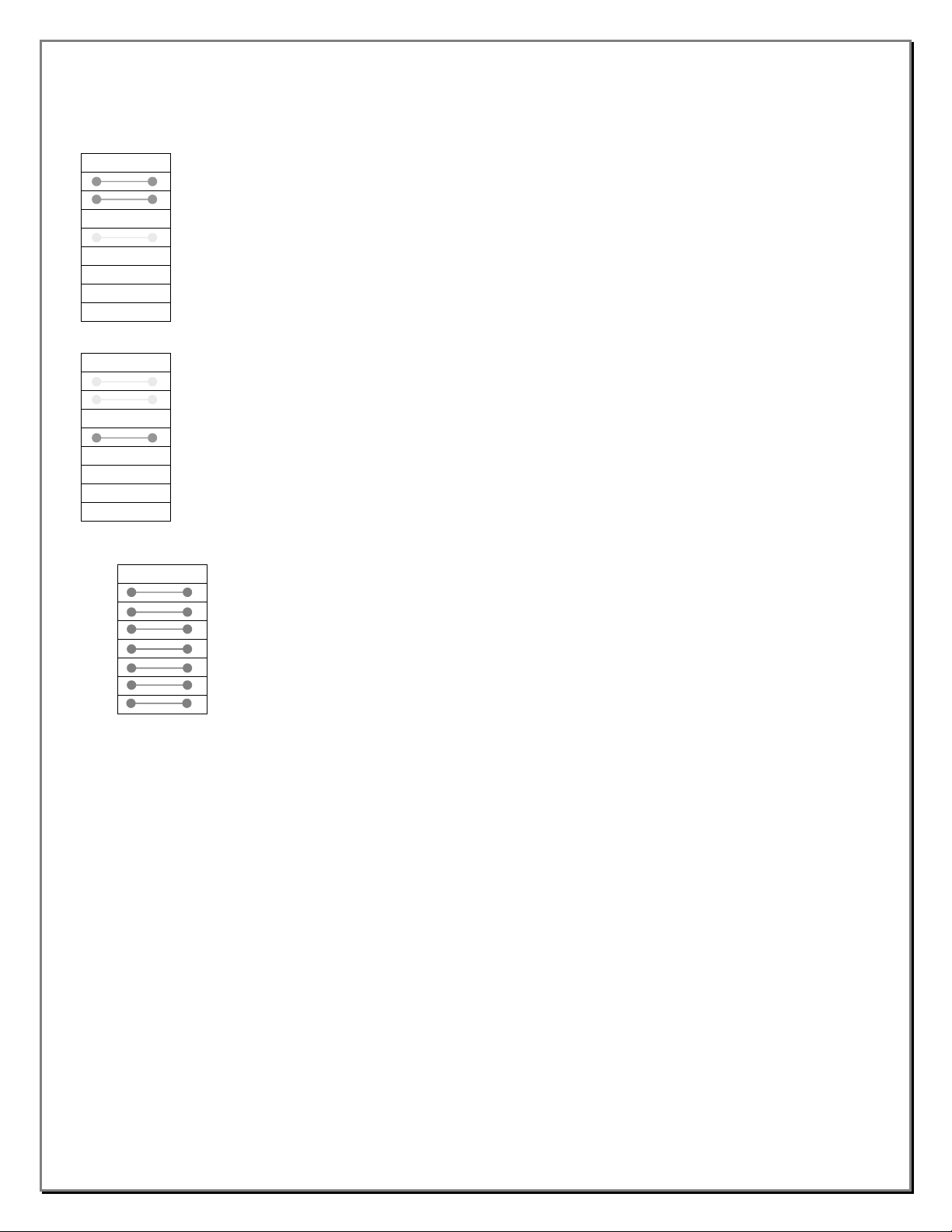
Refer to the APOGEE P1 sensor PCB Layout Drawing 107127 for further details.
1 TEST FULL SCALE (100% OUTPUT)
2 TEST HALF SCALE (50% OUTPUT)
3
4 CUT-OFF (IN/ OUT)
5
6
7
8
1 TEST FULL SCALE (100% OUTPUT)
2 TEST HALF SCALE (50% OUTPUT)
3
4 CUT-OFF (IN/ OUT)
5
6
7
8
H2
RS-485 ADDRESS 1 -127
1 (SET BY BINARY)
2
3
4
5
6
7
Solid-State (SS) Sensors, Output Test: Each sensor
provides a means of driving the output to 50% or
100% full-scale. Respectively, when the onboard test
jumpers are inserted the sensor generates the
selected output signal. This feature is useful for testing
remote devices, which may be connected to the
sensor output.
Solid-State (SS) Sensors, Cut-off Feature: Each
sensor provides a cut-off option to eliminate possible
high background interference of any unsuspected
environmental or other airborne compounds. This
function is jumper selectable. This function is factory
set to enable (jumper in) and is also jumper selectable.
The Carbon Monoxide can be set with a 17ppm cutoff.
Digital Address Binary Code Setup: Each sensor
must be given a unique address code or it will not be
able to communicate correctly. The binary address
code is set by arranging the user selection jumpers
H2 as shown. Arrange jumpers H2-1, H2-2, H2-3,
H2-4, H2-5, H2-6 and H2-7 according to the
appropriate Binary Address Code required for each
application. Refer to Table 1 on page 6 for further
details.
4.0
Page 9

ZGARD S & DS APOGEE P1 Sensors
(EC) Sensor Operating Features and Setup
Electrochemical (EC) Sensors, 0% Output Test:
Each sensor provides a means of driving the output
to 0% full-scale. Respectively, when the onboard test
jumper H1-8 is inserted the sensor generates the
selected output signal. This feature is useful for
testing remote devices, which may be connected to
the sensor output.
Electrochemical (EC) Sensors, 100% Output Test:
Each sensor provides a means of driving the output
to 100% full-scale. Respectively, when the onboard
test jumper H1-9 is inserted the sensor generates the
selected output signal. This feature is useful for
testing remote devices, which may be connected to
the sensor output.
Digital Address Binary Code Setup: Each sensor
must be given a unique address code or it will not be
able to communicate correctly. The binary address
code is set by arranging the user selection jumpers
H1 as shown. Arrange jumpers H1-1, H1-2, H1-3,
H1-4, H1-5, H1-6 and H1-7 according to the
appropriate Binary Address Code required for each
application. Refer to Table 1 on page 6 for further
details.
1
2
4
8
16
32
64
ZS
FS
1
2
4
8
16
32
64
ZS
FS
1
2
4
8
16
32
64
ZS
FS
H1
H1
H1
RS-485 ADDRESS 1 -127
1 (SET BY BINARY)
2
3
4
5
6
7
8 TEST ZERO SCALE (0% OUTPUT)
9 TEST FULL SCALE (100% OUTPUT)
RS-485 ADDRESS 1 -127
1 (SET BY BINARY)
2
3
4
5
6
7
8 TEST ZERO SCALE (0% OUTPUT)
9 TEST FULL SCALE (100% OUTPUT)
RS-485 ADDRESS 1 -127
1 (SET BY BINARY)
2
3
4
5
6
7
8 TEST ZERO SCALE (0% OUTPUT)
9 TEST FULL SCALE (100% OUTPUT)
Refer to the APOGEE P1 sensor PCB Layout Drawings 107128 and 107139 for further details.
Section 5
5.0
Page 10

Section 6
ZGARD S & DS APOGEE P1 Sensors
Digital Binary Address Codes
Table 1
Binary 1 2 4 8 16 32 64
Address
1 IN
2
3 IN IN
4
5 IN
6
7 IN IN IN
8
9 IN
10
11 IN IN
12
13 IN
14
15 IN IN IN IN
16
17 IN
18
19 IN IN
20
21 IN
22
23 IN IN IN
24
25 IN
26
27 IN IN
28
29 IN
30
31 IN IN IN IN IN
32
33 IN
34
35 IN IN
36
37 IN
38
39 IN IN IN
40
41 IN
42
43 IN IN
44
45 IN
46
47 IN IN IN IN
48
H2-1
(H1-1)
OUT
OUT OUT
OUT
OUT OUT OUT
OUT
OUT OUT
OUT
OUT OUT OUT OUT
OUT
OUT OUT
OUT
OUT OUT OUT
OUT
OUT OUT
OUT
OUT OUT OUT OUT OUT
OUT
OUT OUT
OUT
OUT OUT OUT
OUT
OUT OUT
OUT
OUT OUT OUT OUT
H2-2
(H1-2)
OUT OUT OUT OUT OUT OUT
IN
OUT
IN IN
OUT OUT
IN
OUT
IN IN IN
OUT OUT OUT
IN
OUT
IN IN
OUT OUT
IN
OUT
IN IN IN IN
OUT OUT OUT OUT
IN
OUT
IN IN
OUT OUT
IN
OUT
IN IN IN
H2-3
(H1-3)
OUT OUT OUT OUT OUT
OUT OUT OUT OUT OUT
IN
IN
OUT
OUT
IN IN
IN IN
OUT OUT
OUT OUT
IN
IN
OUT
OUT
IN IN IN
IN IN IN
OUT OUT OUT
OUT OUT OUT
IN
IN
OUT
OUT
IN IN
IN IN
H2-4
(H1-4)
OUT OUT OUT OUT
OUT OUT OUT OUT
OUT OUT OUT OUT
OUT OUT OUT OUT
IN
IN
IN
IN
OUT
OUT
OUT
OUT
IN IN
IN IN
IN IN
IN IN
OUT OUT
OUT OUT
OUT OUT
OUT OUT
IN
IN
IN
IN
H2-5
(H1-5)
OUT OUT OUT
OUT OUT OUT
OUT OUT OUT
OUT OUT OUT
OUT OUT OUT
OUT OUT OUT
OUT OUT OUT
OUT OUT OUT
IN
IN
IN
IN
IN
IN
IN
IN
OUT
OUT
OUT
OUT
OUT
OUT
OUT
OUT
IN IN
H2-6
(H1-6)
OUT OUT
OUT OUT
OUT OUT
OUT OUT
OUT OUT
OUT OUT
OUT OUT
OUT OUT
OUT OUT
OUT OUT
OUT OUT
OUT OUT
OUT OUT
OUT OUT
OUT OUT
OUT OUT
IN
IN
IN
IN
IN
IN
IN
IN
IN
IN
IN
IN
IN
IN
IN
IN
H2-7
(H1-7)
OUT
OUT
OUT
OUT
OUT
OUT
OUT
OUT
OUT
OUT
OUT
OUT
OUT
OUT
OUT
OUT
OUT
6.0
Page 11

Section 7
ZGARD S APOGEE P1 (SS) Carbon Monoxide Sensor
Calibration
Calibration Procedure, Solid-State (SS) APOGEE P1 Carbon Monoxide Sensor: Perform calibration checks regularly as
part of a routine inspection and maintenance procedure. Use calibration gases of known and certified concentrations. Check
the expiration date on the gas cylinders. The sensor is factory calibrated for 0-100, 0-200 or 500ppm Carbon Monoxide,
which represents 0 to 100% full scale. The output voltage of 1 to 5Vdc between the test points TPCAL and TPCOM
represents 0 to 100 % full-scale.
WARNING
The calibration procedure must be completed after the replacement of sensing cells. Otherwise it could fail to
perform as designed and persons who rely on this product for their safety could sustain severe personal injury or
death.
Calibration Equipment
Flow controller 0.25 liters/minute and tubing
Purified air as zero gas and 60ppm CO in air span gas
Magnetic Strips
Electronic Multi-meter
Container of Distilled water with inlet and outlet tubing, required for humidifying the calibration gas. Refer to the (SS)
sensors Calibration Gas (Humidified) Setup Procedure Drawing 107129 for further details.
Calibration Procedure
1. Disconnect the sensor output from the associated monitoring device. Using a multi-meter insert test probes into test point
terminals labelled TPCAL & TPCOM.
2. Insert Jumper H1-4 to disable the sensor cut-off feature.
3. Place the magnetic strips on the top and bottom of the sensor cover plate, ensure the vent holes are fully covered.
WARNING
Remove the magnetic strips after the calibration has been completed. Otherwise it could fail to perform as designed
and persons who rely on this product for their safety could sustain severe personal injury or death.
ZERO Calibration
4. Join a 0.25 l/m. flow controller onto a ZERO gas cylinder. Insert a calibration adapter into thread port provided on the
protective cover located on the front plate.
5. Connect the ¼” Tygon tubing between the inlet of the gas humidification assembly and the calibration cylinder flow
controller outlet port.
6. Connect the outlet tubing of the gas humidification assembly to the sensor calibration adapter.
7. Turn ON the flow controller valve and allow the ZERO grade air to quench the sensor for at least 15 minutes.
8. Adjust the ZERO potentiometer until the output voltage is equal to 1Vdc.
9. Turn OFF the valve and remove the flow controller from the Zero gas cylinder.
SPAN Calibration
10. Join the flow controller onto a SPAN gas cylinder. The SPAN gas should be at least 50% of the sensor’s operating range.
11. Turn ON the flow controller valve and allow the SPAN gas to quench the sensor for at least 15 minutes.
12. Adjust the SPAN potentiometer until the output voltage is equal to the calculated value representing the gas
concentration. See the example equation below.
13. Turn OFF the valve and remove the flow controller from the SPAN gas cylinder.
14. Remove the test hose from the calibration adapter.
15. Remove the multi-meter test probes from terminals labelled TPCAL and TPCOM.
16. Reconnect the sensor output to the associated monitoring device.
17. Remove Jumper H1-4 to enable the sensor cut-off feature.
Example: The SPAN gas concentration is 60ppm Carbon Monoxide in air.
1 - 5Vdc is 0-100% F.S., the voltage that is generated is 4 + 1 = 5Vdc.
60ppm = ((Span Gas Value x 4) / Full Scale)) + 1 = ((60 x 4) / 100)) + 1 = 3.4Vdc
7.0
Page 12

Section 8
ZGARD S & DS APOGEE P1 (EC) Carbon Monoxide Sensor
Calibration
Calibration Procedure, Electrochemical (EC) APOGEE P1 Carbon Monoxide Sensor: Perform calibration checks
regularly as part of a routine inspection and maintenance procedure. Use calibration gases of known and certified
concentrations. Check the expiration date on the gas cylinders. The sensor is factory calibrated for 0-100 or 0-200ppm
Carbon Monoxide, which represents 0 to 100% full scale. The output voltage of 1 to 5Vdc between the test points TPCAL
and TPCOM represents 0 to 100 % full-scale.
WARNING
The calibration procedure must be completed after the replacement of sensing cells. Otherwise it could fail to
perform as designed and persons who rely on this product for their safety could sustain severe personal injury or
death.
Calibration Equipment
Flow controller 0.25 liters/minute and tubing
Purified air as zero gas
60ppm CO in air span gas
Magnetic Strips
Electronic Multi-meter
Calibration Procedure
1. Disconnect the sensor output from the associated monitoring device. Using a multi-meter insert two test probes into the
test point terminals labelled TPCAL & TPCOM.
2. Place the magnetic strips on the top and bottom of the sensor cover plate, ensure the vent holes are fully covered.
WARNING
Remove the magnetic strips after the calibration has been completed. Otherwise it could fail to perform as designed
and persons who rely on this product for their safety could sustain severe personal injury or death.
ZERO Calibration
3. Attach a 0.25 l/m., flow controller onto a ZERO gas cylinder. Insert a calibration adapter into thread port provided on the
protective cover located on the front plate.
4. Connect ¼” Tygon tubing to the outlet of the flow controller, and then slip the open end on the calibration adapter.
5. Turn ON the flow controller valve and allow the ZERO grade air to quench the sensor for at least 2 minutes.
6. Adjust the ZERO potentiometer until the output voltage is equal to 1Vdc.
7. Turn OFF the valve and remove the flow controller from the Zero gas cylinder.
SPAN Calibration
8. Attach the flow controller onto a SPAN gas cylinder. The SPAN gas should be at least 50% of the sensor’s operating
range.
9. Turn ON the flow controller valve and allow the SPAN gas to quench the sensor for at least 2 minutes.
10. Adjust the SPAN potentiometer until the output voltage is equal to the calculated value representing the gas
concentration. See the example equation below.
11. Turn OFF the valve and remove the flow controller from the SPAN gas cylinder.
12. Remove the test hose from the calibration adapter.
13. Remove the multi-meter test probes from terminals labelled TPCAL and TPCOM.
14. Reconnect the sensor output to the associated monitoring device.
Example: The SPAN gas concentration is 60ppm Carbon Monoxide in air.
1-5Vdc is 0-100% F.S., the voltage that is generated is 4 + 1 = 5Vdc.
60ppm = ((Span Gas Value x 4) / Full Scale)) + 1 = ((60 x 4) / 100)) + 1 = 3.4Vdc
8.0
Page 13

Section 9
ZGARD S & DS APOGEE P1 (EC) Nitrogen Dioxide Sensor
Calibration
Calibration Procedure, Electrochemical (EC) APOGEE P1 Nitrogen Dioxide Sensor: Perform calibration checks
regularly as part of a routine inspection and maintenance procedure. Use calibration gases of known and certified
concentrations. Check the expiration date on the gas cylinders. The sensor is factory calibrated for 0-10ppm Nitrogen
Dioxide, which represents 0 to 100% full scale. The output voltage of 1 to 5Vdc between the test points TPCAL and TPCOM
represents 0 to 100 % full-scale.
WARNING
The calibration procedure must be completed after the replacement of sensing cells. Otherwise it could fail to
perform as designed and persons who rely on this product for their safety could sustain severe personal injury or
death.
Calibration Equipment
Flow controller 0.25 liters/minute and tubing
Purified air as zero gas
10ppm NO2 in air span gas
Magnetic Strips
Electronic Multi-meter
Calibration Procedure
1. Disconnect the sensor output from the associated monitoring device. Using a multi-meter, insert two test probes into the
test point terminals labelled TPCAL & TPCOM.
2. Place the magnetic strips on the top and bottom of the sensor cover plate, ensure the vent holes are fully covered.
WARNING
Remove the magnetic strips after the calibration has been completed. Otherwise it could fail to perform as designed
and persons who rely on this product for their safety could sustain severe personal injury or death.
ZERO Calibration
3. Attach a 0.25 l/m., flow controller onto a ZERO gas cylinder. Insert a calibration adapter into thread port provided on the
protective cover located on the front plate.
4. Connect ¼” Tygon tubing to the outlet of the flow controller, and then slip the open end on the calibration adapter.
5. Turn ON the flow controller valve and allow the ZERO grade air to quench the sensor for at least 2 minutes.
6. Adjust the ZERO potentiometer until the output voltage is equal to 1Vdc.
7. Turn OFF the valve and remove the flow controller from the Zero gas cylinder.
SPAN Calibration
8. Attach the flow controller onto a SPAN gas cylinder. The SPAN gas should be at least 50% of the sensor’s operating
range.
9. Turn ON the flow controller valve and allow the SPAN gas to quench the sensor for at least 2 minutes.
10. Adjust the SPAN potentiometer until the output voltage is equal to the calculated value representing the gas
concentration. See the example equation below.
11. Turn OFF the valve and remove the flow controller from the SPAN gas cylinder.
12. Remove the test hose from the calibration adapter.
13. Remove the multi-meter test probes from terminals labelled TPCAL and TPCOM.
14. Reconnect the sensor output to the associated monitoring device.
Example: The SPAN gas concentration is 10ppm Nitrogen Dioxide in air.
1-5Vdc is 0-100% F.S., the voltage that is generated is 4 + 1 = 5Vdc.
10ppm = ((Span Gas Value x 4) / Full Scale)) + 1 = ((10 x 4) / 10)) + 1 = 5.0Vdc
9.0
Page 14

Section 10
ZGARD S & DS APOGEE P1 Sensors
Start-Up Procedure
9 Apply the appropriate operating power to the sensor.
9 The green Sensor OK LED Indicator on front of the sensor should be ON after a 30 second delay. This
will also indicate that the device is operating properly.
9 Allow a few minutes for the sensor to stabilize.
9 Insert Test Jumper H1-Full Scale (FS) into the test position. This should drive the sensor output to 100%
full-scale. If the sensor is connected to a gas monitoring instrument, check that the readings correspond
with that device.
9 Remove Test Jumper H1-Full Scale (FS) from the test position.
Note! Check the binary code jumper H1 on EC and H2 on SS version. They must be correctly positioned to
reflect the unique address number of each remote sensor connected to the host Siemens controller. Refer to
Table 1 on page 6 for further details.
BUMP TEST: Apply a representative sample gas to each sensor and simply check if the sensor responds to the
target gas and has reached the appropriate value.
Note! Any remote equipment, which may be connected to a remote device, may be activated.
The initial function test of the ZGARD S & DS APOGEE P1 sensor is now completed.
10.0
Page 15
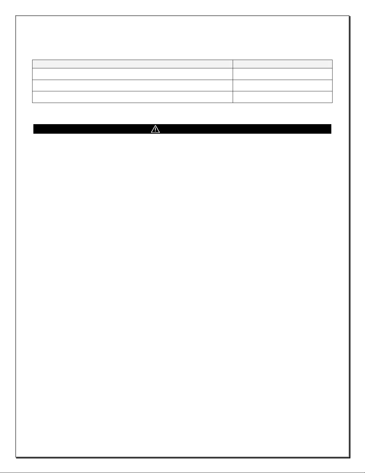
ZGARD S & DS APOGEE P1 Sensors
Item Part Number
Replacement Electrochemical (EC) CO Cell Assembly
10064004
Section 11
Parts List
Replacement Electrochemical (EC) NO2 Cell Assembly
Replacement Solid-State (SS) CO Cell Assembly
10064003
10063828
* When ordering replacement parts, please state the MSA P/N and S/N of unit.
WARNING
Use only genuine MSA replacement parts when performing any maintenance on the ZGARD S
& DS APOGEE P1 gas sensors. Failure to do so may seriously impair instrument performance.
Repair or alteration of the ZGARD S & DS APOGEE P1 gas sensors, beyond the scope of these
maintenance instructions or by anyone other than authorized MSA service personnel, could
cause the product to fail to perform as designed, and persons who rely on this product for
their safety could sustain serious personal injury or death.
Disconnect all power source(s) to the ZGARD S & DS APOGEE P1 Sensors before removing or
changing any components.
11.0
Page 16

Page 17

Page 18

Page 19

Page 20

 Loading...