

Page 1
MSAsafety.com
US
Instruction and Safety Manual
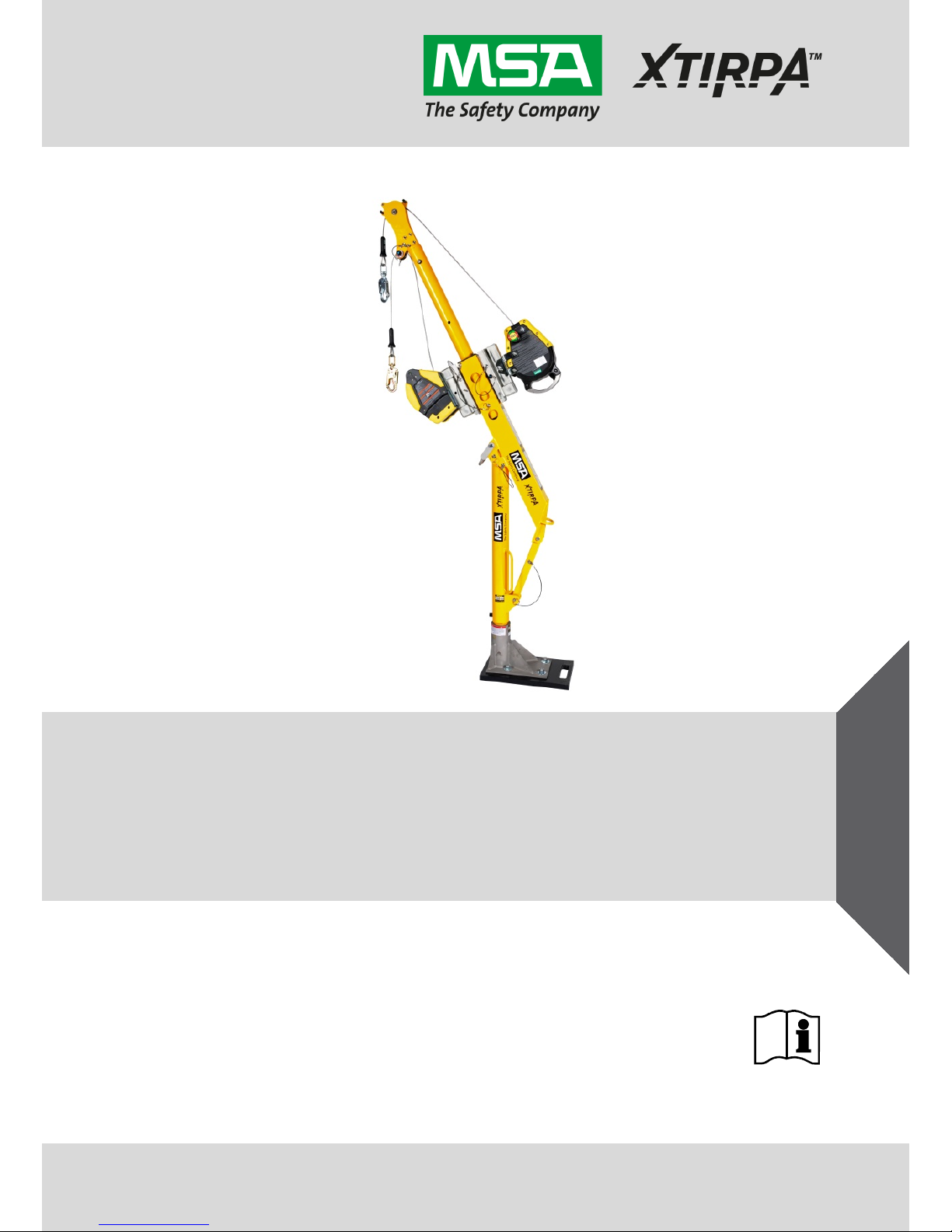
MSA/XTIRPA™ Adapter Base System
24" Reach
Order No.: 10171018/00
Visit: www.thesafetyequipmentstore.com Or Email: besafe@thesafetyequipmentstore.com for Sales & Service.
Page 2

© MSA 2015. All rights reserved
Warning
National standards and state, provincial, and federal laws require
the user to be trained before using this product. Use this manual as
part of a user safety training program that is appropriate for the
user’s occupation. These instructions must be provided to users
before use of the product and retained for ready reference by the
user. The user must read, understand (or have explained), and
heed all instructions, labels, markings, and warnings supplied with
this product and with these products intended f
or use in association
with it. Failure to do so may result in death or serious injury.
XTIRPA™ products are manufactured by Innova Public Utility Products Inc.
Made in Canada.
XTIRPA™ is a Registered Trademark of Innova Public Utility Products Inc.,
used under license in North America and Europe.
Mine Safety Appliances Company
1000 Cranberry Woods Drive
Cranberry Township, PA 16066
United States
For More Information, call 1-800-MSA-2222 or Visit Our Website at
www.MSAsafety.com
Visit: www.thesafetyequipmentstore.com Or Email: besafe@thesafetyequipmentstore.com for Sales & Service.
Page 3

Contents
MSA/XTIRPA™ Adapter Base System 24" Reach 3
US
Contents
1. Safety Regulations .............................................................................. 4
1.1. Correct Use................................................................................ 4
1.2. Usage Limitations ...................................................................... 5
1.2.1 Physical Limitations ................................................................... 5
1.2.2 Hazards ..................................................................................... 6
1.3. Liability Information .................................................................... 6
1.4. Safety and Precautionary Measures to be Adopted ................... 7
1.5. Warranty .................................................................................... 8
2. Description .......................................................................................... 9
2.1. Labels and Markings .................................................................. 9
2.2. System Requirements ............................................................. 11
2.2.1 Compatibility of Components and Subsystems........................ 11
2.2.2 Compatibility of Connectors ..................................................... 12
3. Use ..................................................................................................... 13
3.1. Planning the Use of Systems ................................................... 13
3.1.1 Rescue and Evacuation ........................................................... 13
3.1.2 Free Fall Distance .................................................................... 13
3.2. Pre-Use Inspection .................................................................. 14
3.3. Assembly ................................................................................. 14
4. Cleaning and Maintenance ............................................................... 22
4.1. Cleaning .................................................................................. 22
4.2. Maintenance ............................................................................ 22
5. Inspection .......................................................................................... 23
5.1. Inspection Frequency .............................................................. 23
5.2. Formal Inspection .................................................................... 23
5.3. Procedure for Inspection .......................................................... 23
5.4. Corrective Action ..................................................................... 24
5.5. Inspection Log ......................................................................... 24
6. Storage............................................................................................... 26
Visit: www.thesafetyequipmentstore.com Or Email: besafe@thesafetyequipmentstore.com for Sales & Service.
Page 4

Safety Regulations
4 MSA/XTIRPA™ Adapter Base System 24" Reach
US
US
1. Safety Regulations
1.1. Correct Use
The Adapter Base System (hereinafter also called confined space
system) is part of a personal fall arrest, work positioning, personnel
riding, material handling or rescue system for use in confined spaces.
All confined space systems meet applicable OSHA regulations.
The confined space system is designed to be integrated as part of a
complete fall arrest system with a maximum arrest force of 1,800lbf
(8kN). The confined space system is designed to maintain a safety factor
of two, and is to be assembled and used under the supervision of a
qualified person, as required by OSHA. The confined space system is
designed for use by one person.
It is imperative to evaluate the capacity rating of all products incorporated
within the fall arrest system. The capacity of a fall arrest system is the
lowest capacity rating of any product (anchorage connector, SRL, etc.)
integrated in the fall arrest system.
The Adapter Base System anchorage connector is comprised of three
primary components, the davit arm, the mast, and the 3" diameter
adapter base. The Adapter Base System capacity for fall arrest,
personnel riding, rescue, and material handling is as follows:
- 360lbs (163kg) - If using davit arm IN-2210, mast IN-2003, and any
3" diameter adapter base
- 360lbs (163kg) - If using integrated mast and davit arm IN-2295 or
IN-2363, and any 3" diameter adapter base
Capacity for personnel includes the weight of the user plus clothing,
tools, and other user-borne objects.
Free fall distance (limit) must not exceed 6ft (1.8m) in accordance with
OSHA. The Canadian Occupational Health & Safety Act of 1990
specifies that free fall distance must not exceed 5ft (1.5m). The user
must comply with applicable standards and regulations.
When used as part of a personal fall arrest system, fall arresting forces
must not exceed 1,800lbf (8kN).
Warning
If PPE is resold, it is essential that instructions for use maintenance and
periodic examination are provided in the language of destination. Failure
to follow this warning may result in death or serious injury.
Visit: www.thesafetyequipmentstore.com Or Email: besafe@thesafetyequipmentstore.com for Sales & Service.
Page 5
Safety Regulations
MSA/XTIRPA™ Adapter Base System 24" Reach 5
US
The Adapter Base System is intended for use by trained and qualified
personnel.
It is imperative that this instruction and safety manual be read and
observed when using the product. In particular, the safety instructions, as
well as the information for the use and operation of the product, must be
carefully read and observed. Furthermore, the national regulations
applicable in the user's country must be taken into account for a safe
use.
Alternative use, or use outside this specification will be considered as
non-compliance. This also applies especially to unauthorized alterations
to the product and to commissioning work that has not been carried out
by MSA or authorized persons.
1.2. Usage Limitations
The following applications limitations must be considered and planned for
before using the confined space system.
1.2.1 Physical Limitations
Persons with muscular, skeletal, or other physical disorders should
consult a physician before using a personal fall arrest system that
includes the confined space system. Pregnant women and minors must
never use these systems.
Increasing age and lowered physical fitness may reduce a person’s
ability to withstand shock loads during fall arrest or prolonged
suspension. Consult a physician if there is any question about physical
ability to safely use this product to arrest a fall or suspend.
Warning
Do not alter this equipment or misuse it. A full body harness is the only
acceptable body holding device that can be used in a fall arrest system.
Failure to follow this warning may result in death or serious injury.
Visit: www.thesafetyequipmentstore.com Or Email: besafe@thesafetyequipmentstore.com for Sales & Service.
Page 6

Safety Regulations
6 MSA/XTIRPA™ Adapter Base System 24" Reach
US
US
1.2.2 Hazards
Acidic, alkaline, or other environments with harsh substances may
damage the hardware elements in the confined space system. If working
in a chemically aggressive environment, consult MSA to determine
acceptable system components for your specific conditions.
Chemical hazards, heat and corrosion may damage the confined space
system. More frequent formal inspections are required in environments
with chemical hazards, heat and corrosion.
Do not expose to corrosive environments for prolonged periods. Use
extreme caution when working near energized electrical sources.
Maintain a safe working distance (preferably at least 10 feet (3m)) from
electrical hazards. When working near moving machinery parts
(e.g. conveyors, rotating shafts, presses, etc.), make sure that there are
no loose elements in any part of the system.
Any confined space system which shows signs of excessive wear,
deterioration or malfunction must be removed from use and marked
“UNUSABLE” until repaired.
Any confined space system which has been subjected to the forces of a
fall must be immediately removed from service and marked
“UNUSABLE” until submitted to, and released from, formal inspection.
1.3. Liability Information
MSA accepts no liability in cases where the product has been used
inappropriately or not as intended. The selection and use of this product
must be under the direction of a qualified safety professional who has
carefully evaluated the specific hazards of the jobsite where it will be
used and who is completely familiar with the product and its limitations.
The selection and use of this product and its incorporation into the safety
scheme of the jobsite is the exclusive responsibility of the employer.
Product liability claims, warranties also as guarantees made by MSA with
respect to the product are voided, if it is not used, serviced or maintained
in accordance with the instructions in this manual.
Visit: www.thesafetyequipmentstore.com Or Email: besafe@thesafetyequipmentstore.com for Sales & Service.
Page 7

Safety Regulations
MSA/XTIRPA™ Adapter Base System 24" Reach 7
US
1.4. Safety and Precautionary Measures to be Adopted
Users of MSA products must be familiar with the user instructions and be
trained by a competent person in:
- workplace hazard identification, evaluation and control
- selection, inspection, use, storage, and maintenance
- usage planning including calculation of free and total fall distance;
maximum arresting force
- compatibility and selection of anchorage/anchorage connectors
including connection to help prevent accidental disengagement
(rollout)
- proper lanyard/harness connection locations
- evacuation and rescue planning and implementation
- consequences of improper use
For Confined Space Applications:
- See OSHA 29 CFR 1910.146
Periodically (at least annually) assess effectiveness of training and
determine the need for retraining or additional training. Contact MSA for
training information.
Visit: www.thesafetyequipmentstore.com Or Email: besafe@thesafetyequipmentstore.com for Sales & Service.
Page 8

Safety Regulations
8 MSA/XTIRPA™ Adapter Base System 24" Reach
US
US
1.5. Warranty
Express Warranty- MSA warrants that the product furnished is free
from mechanical defects or faulty workmanship for a period of two (2)
years from date of shipment, provided it is maintained and used in
accordance with MSA’s instructions and/or recommendations.
MSA shall be released from all obligations under this warranty in the
event repairs or modifications are made by persons other than its own
authorized service personnel or if the warranty claim results from misu
se
of the product.
No agent, employee or representative of MSA may bind MSA to any
affirmation, representation or modification of the warranty concerning the
goods sold under this contract. MSA makes no warranty concerning
components or accessories not manufactured by MSA, but will pass on
the Purchaser all warranties of manufacturers of such components.
This warranty is in lieu of all other warranties, express, implied or
statutory, and is strictly limited to the terms hereof, MSA specifically
disclaims any warranty of merchantability or fitness for a particular
purpose.
Exclusive Remedy-
It is expressly agreed that the Purchaser’s sole and
exclusive remedy for breach of the above warranty, for any tortious
conduct of MSA, or for any other cause of action, shall be the repair
and/or replacement, at MSA’s option, of any equipment or parts thereof,
that after examination by MSA are proven to be defective.
Replacement equipment and/or parts will be provided at no cost to the
Purchaser, F.O.B. Purchaser’s named place of destination.
Failure of MSA to successfully repair any nonconforming product shall
not cause the remedy established hereby to fail of its essential purpose.
Exclusion of Consequential Damages- The Purchaser specifically
understands and agrees that under no circumstances will MSA be liable
to the Purchaser for economic, special, incidental, or consequential
damages or loses of any kind whatsoever, including but not limited to
loss of anticipated profits and any other loss caused by reason of the
non-operation of the goods. This exclusion is applicable to claims for
breach of warranty, tortious conduct of any other cause of action against
MSA.
For additional information please contact the Customer Service
Department at 1-800-MSA-2222 (1-800-672-2222).
Visit: www.thesafetyequipmentstore.com Or Email: besafe@thesafetyequipmentstore.com for Sales & Service.
Page 9
Description
MSA/XTIRPA™ Adapter Base System 24" Reach 9
US
2. Description
The confined space system is an anchorage connector for users needing
a personal fall arrest, work positioning, personnel riding, material
handling or rescue system for use in confined spaces.
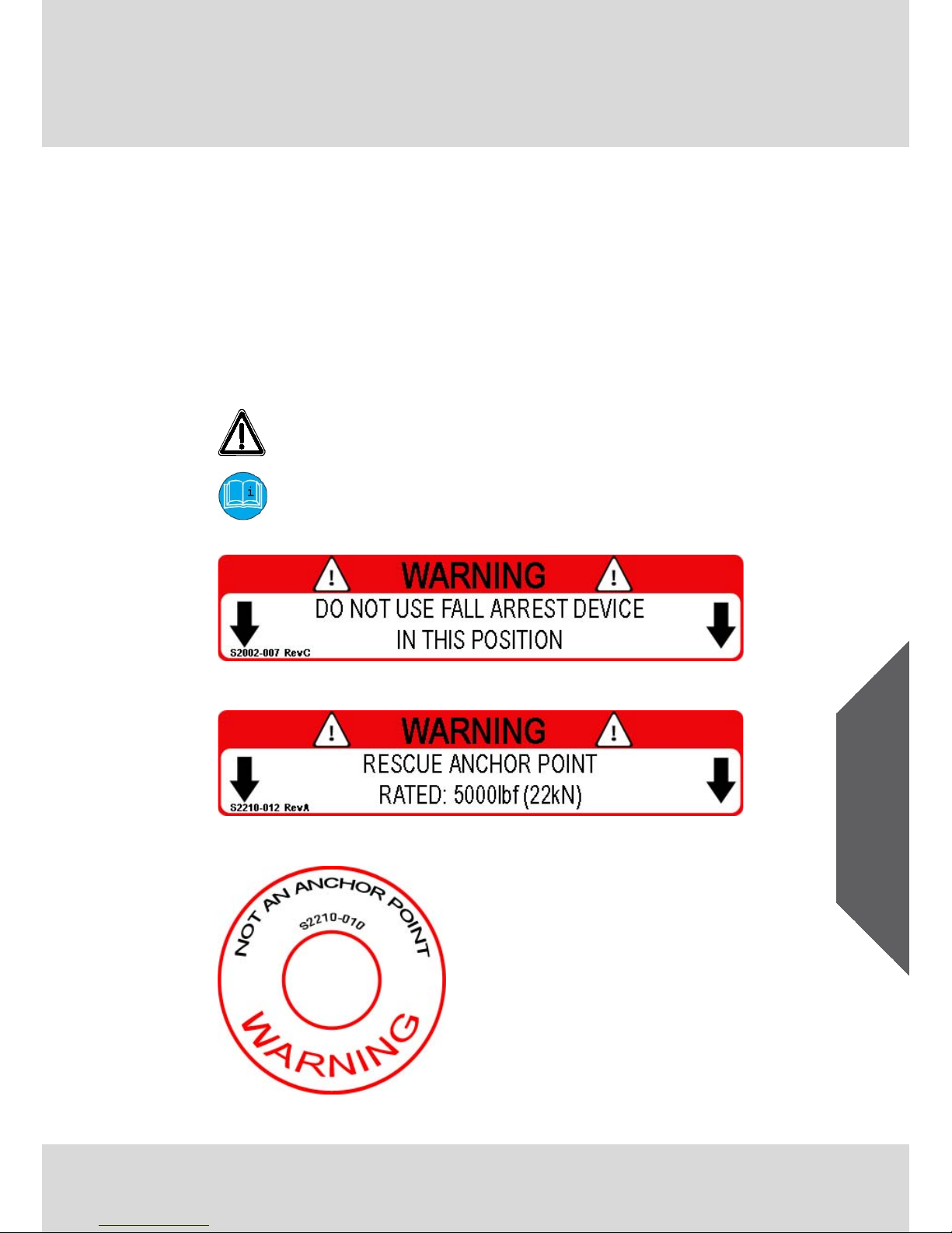
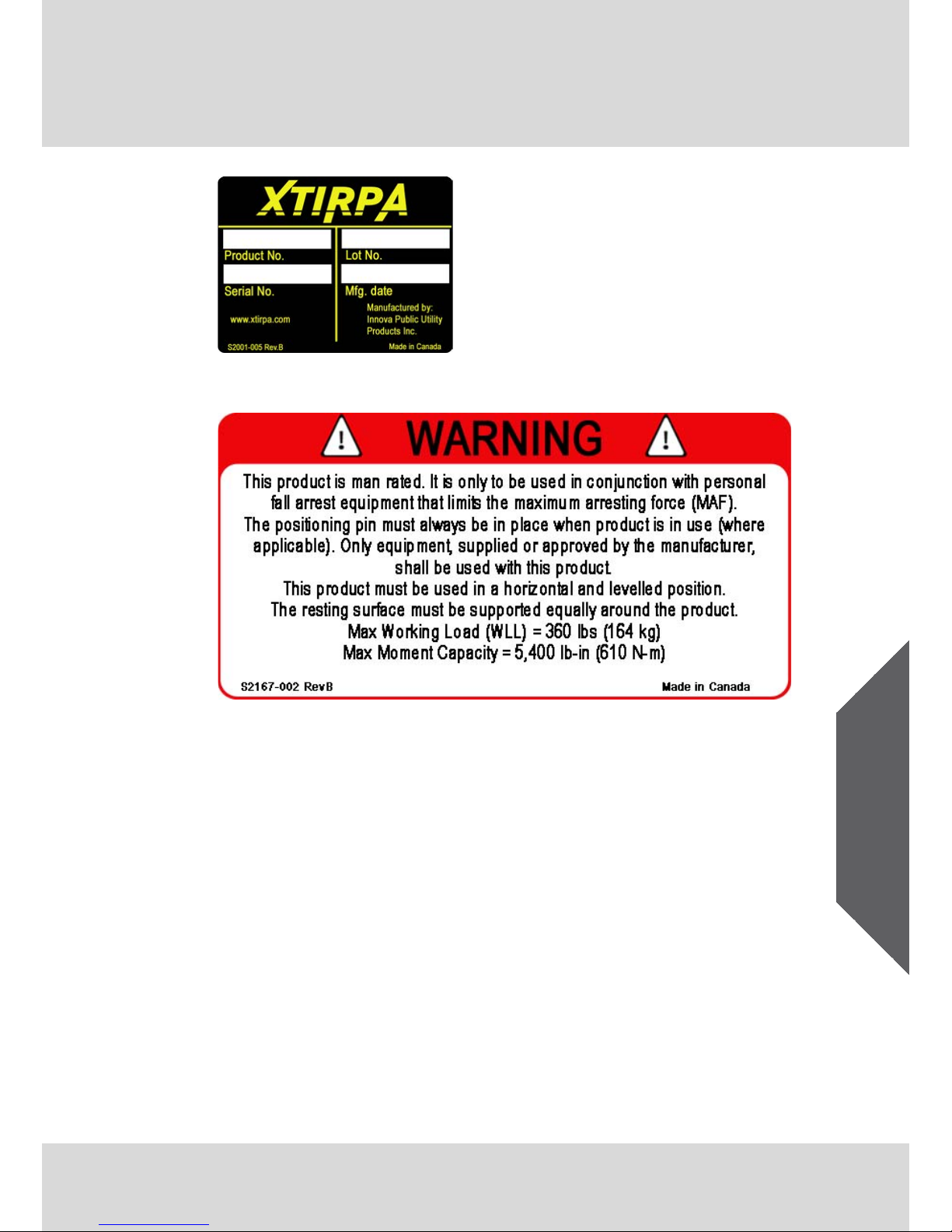
2.1. Labels and Markings
The following labels must be present, legible and securely attached to
the confined space system.
This symbol is used to signalize the user of a potential hazard.
The safety of the worker is in jeopardy. It is imperative to follow
manufacturer’s recommendation.
This symbol asks the user to read and understand the manual
for this product before use.
Fig. 1 Device Positioning Warning Sticker
Fig. 2 Rescue Anchor Point Warning Sticker
Fig. 3 Not an Anchor Point Warning Sticker
Page 10
Description
10 MSA/XTIRPA™ Adapter Base System 24" Reach
US
US
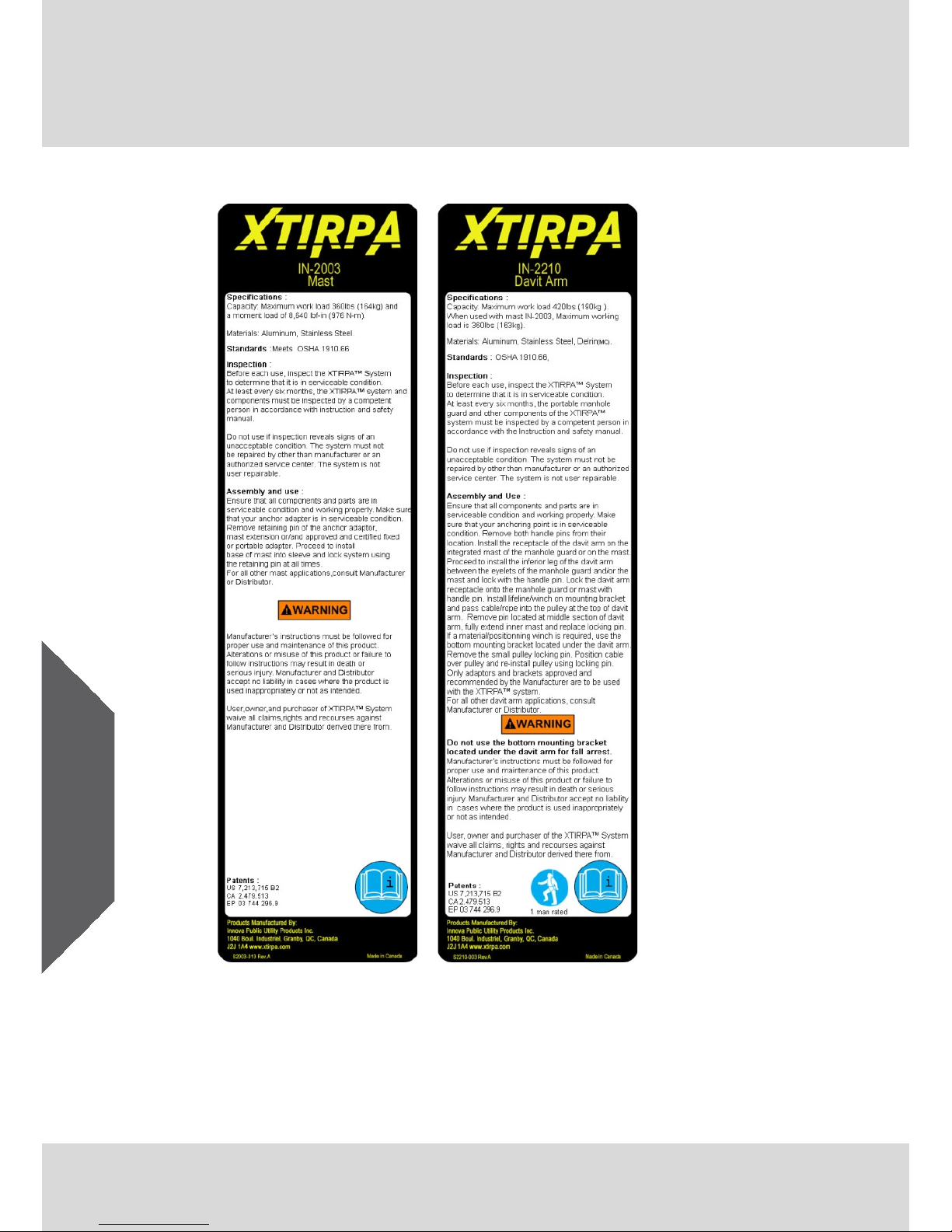
Fig. 4 Mast Label Fig. 5 Davit Arm
Label
Page 11
Description
MSA/XTIRPA™ Adapter Base System 24" Reach 11
US
Fig. 6 Product Data Sticker
Fig. 7 Man Rated Label
2.2. System Requirements
2.2.1 Compatibility of Components and Subsystems
The confined space system is designed to be used with MSA fall
protection components and connecting subsystems. MSA fall protection
equipment has been evaluated and tested in accordance with applicable
standards to be compatible when combined in ways stipulated in MSA
product user instructions.
Combining fall protection components and connecting subsystems made
by different manufacturers may adversely affect the functional
compatibility between system parts and the safety and reliability of the
complete system.
It is the responsibility of the employer’s designated competent person to
determine the compatibility of fall protection components and
subsystems. MSA recommends if choosing to combine fall protection
components and connecting subsystems from different manufacturers,
Page 12

Description
12 MSA/XTIRPA™ Adapter Base System 24" Reach
US
US
all components and connecting subsystems should be approved to
comply with the applicable ANSI, CSA, or EN standard(s).
For fall arrest applications using the confined space system, the
maximum fall arrest force must not exceed 1,800lbf (8kN). Contact MSA
with any questions regarding compatibility of equipment used with the
confined space system.
2.2.2 Compatibility of Connectors
Connectors such as D-rings, snaphooks, and carabiners must be rated to
5000lbf (22kN) minimum breaking strength. Per ANSI Z359.12 and
CSA Z259.12, connector gates must be able to withstand a load of
3,600lbf (16kN). Connecting hardware must be compatible in size and
shape as to not inadvertently cause their gate mechanisms to open.
Non-compatible connectors may accidentally disengage. Always verify
compatibility of the connecting snaphook or carabiner with harness
D-ring or anchorage connector. Use only self-closing, self-locking
snaphooks and carabiners with the harness.
When using a snaphook to connect to an anchorage or when coupling
components of the system together, be certain accidental
disengagement (rollout) cannot occur.
Rollout is possible when interference between a snaphook and the
mating connector causes the snaphook’s gate or keeper to accidentally
open and release. Rollout occurs when a snaphook is snapped into an
undersized ring such as an eye bolt or other non-compatibly shaped
connector.
Do not use snaphooks or connectors that will not completely close over
the attachment object. Do not make knots in a lanyard. Do not hook the
lanyard back onto itself. Snaphooks and carabiners must not be
connected to each other. Do not attach two snaphooks into one D-ring.
Always follow the manufacturer’s instructions supplied with each system
component.
Warning
Do not rely on feel or sound to verify proper snaphook engagement.
Always check visually for proper engagement. Ensure that gate and
keeper are closed before use. Failure to follow this warning may result in
death or serious injury.
Page 13

Use
MSA/XTIRPA™ Adapter Base System 24" Reach 13
US
3. Use
3.1. Planning the Use of Systems
3.1.1 Rescue and Evacuation
The user must have a rescue plan and the means at hand to implement
it. The plan must take into account the equipment and special training
necessary to affect prompt rescue under all foreseeable conditions.
If the rescue is from a confined space, the provisions of
OSHA regulation 1910.146 must be taken into account.
Although a rescue plan and the means to implement it must always be in
place, it is a good idea to provide means for user evacuation without
assistance of others. This will usually reduce the time to get to a safe
place and reduce or prevent the risk to rescuers.
If the confined space system is to be included as a part of rescue or
evacuation systems, the optional system components required, the time
required to erect the confined space system and attach any optional
components and the anchorage requirements should be considered
when planning these systems.
3.1.2 Free Fall Distance
Do not exceed free fall distance specified by applicable regulations and
standards. When using a shock absorbing lanyard, keep the amount of
slack between the anchorage/anchorage connector and the harness at a
minimum to reduce the free fall distance and the impact force to the user.
Make certain that enough clearance is available in all potential fall paths
to prevent striking an object. The amount of clearance needed depends
upon the type of connecting subsystem used, and the location of the
anchorage or anchorage connector.
Consult the manufacturer’s instructions for the particular connecting
subsystem or component for clearance needed.
Warning
Prevent swing falls and impact with objects in
or adjacent to the fall path.
Always remove obstructions below the work area to ensure a clear fall
path. Work directly under the anchorage/anchorage connector at all
times. Failure to follow this warning may result in death or serious injury.
Visit: www.thesafetyequipmentstore.com Or Email: besafe@thesafetyequipmentstore.com for Sales & Service.
Page 14

Use
14 MSA/XTIRPA™ Adapter Base System 24" Reach
US
US
Caution
Keep work area free from obstructions, trip hazards, and spills which
could impair the safe operation of the fall-rescue system.
Do not open the confined space access cover before complete
installation of the anchorage connector and all other system
components.
3.2. Pre-Use Inspection
Inspect the confined space system to verify that it is in serviceable
condition. Examine every inch of the confined space system for severe
wear, missing or broken elements, corrosion, or other damage. Do not
use the confined space system if inspection reveals an unsafe condition.
3.3. Assembly
Always work in teams of at least two (2) people (one (1) attendant and
one (1) confined space worker) who are qualified and trained on the
confined space system.
(1.) Remove all components and parts from bags, boxes, or shipping
container and set all on ground. Make sure that components are in
good working condition.
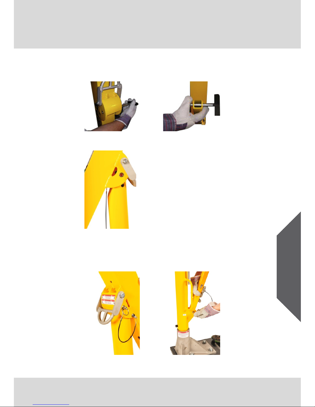
(2.) Insert the mast into the Adapter Base sleeve (A) and lock with a
pin (B). If using integrated mast and davit arm IN-2295 or IN-2363,
proceed to Step 5.
Fig. 8 Step 2A
Fig. 9 Step 2B
Visit: www.thesafetyequipmentstore.com Or Email: besafe@thesafetyequipmentstore.com for Sales & Service.
Page 15
Use
MSA/XTIRPA™ Adapter Base System 24" Reach 15
US
(3.) To install the davit arm on the mast, remove both handle pins from
their locations (A) & (B). Install the receptacle of the davit arm on the
mast (C).
Fig. 10 Step 3A
Fig. 11 Step 3B
Fig. 12 Step 3C
(4.) Lock the davit arm with the first handle pin (A), then install the lower
leg of the davit arm between the eyelets of the mast and lock with
the second handle pin (B).
Fig. 13 Step 4A
Fig. 14 Step 4B
Visit: www.thesafetyequipmentstore.com Or Email: besafe@thesafetyequipmentstore.com for Sales & Service.
Page 16
Use
16 MSA/XTIRPA™ Adapter Base System 24" Reach
US
US
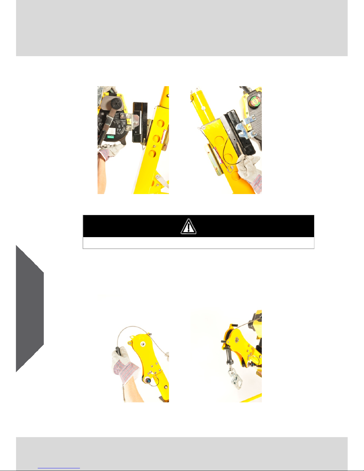
(5.) Install the SRL or winch on the applicable top mounting bracket (A)
and lock with the pin attached to the SRL or winch bracket (B).
Fig. 15 Step 5A
Fig. 16 Step 5B
Warning
Use only MSA approved adapters and brackets.
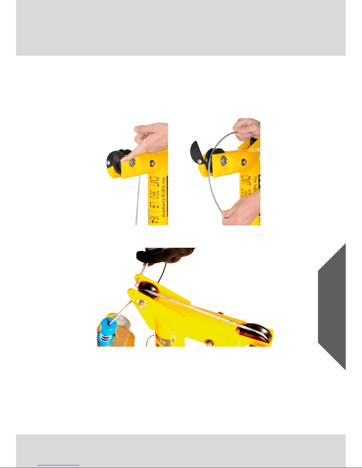
(6.) If using davit arm IN-2210 and mast IN-2003, pass the cable or rope
lifeline into the pulley located at the top end of the davit arm (A). Be
assured that the cable or rope lifeline is fully seated within the pulley
groove (B).
Fig. 17 Step 6A
Fig. 18 Step 6B
Visit: www.thesafetyequipmentstore.com Or Email: besafe@thesafetyequipmentstore.com for Sales & Service.
Page 17
Use
MSA/XTIRPA™ Adapter Base System 24" Reach 17
US
If using the integrated mast and the davit arm IN-2295 or IN-2363,
remove the small pulley pin and rotate the half-moon plate (C) to
pass the cable or rope lifeline into the pulleys (D). Return the half
moon plate to its original position and lock with the small pulley
pin (E). Be assured that the cable or rope lifeline is fully seated
within the pulley groove.
Fig. 19 Step 6C
Fig. 20 Step 6D
Fig. 21 Step 6E
Visit: www.thesafetyequipmentstore.com Or Email: besafe@thesafetyequipmentstore.com for Sales & Service.
Page 18

Use
18 MSA/XTIRPA™ Adapter Base System 24" Reach
US
US
(7.) If a material positioning winch is required while using davit arm
IN-2210 and mast IN-2003, use the bottom mounting bracket located
under the davit arm. Install the winch to the mounting bracket (A)
and lock with the pin attached to the winch (B). Remove the small
pulley locking pin (C). Position the cable over the pulley and reinstall using the locking pin (D).
Fig. 22 Step 7A
Fig. 23 Step 7B
Fig. 24 Step 7C
Fig. 25 Step 7D
Visit: www.thesafetyequipmentstore.com Or Email: besafe@thesafetyequipmentstore.com for Sales & Service.
Page 19

Use
MSA/XTIRPA™ Adapter Base System 24" Reach 19
US
Warning
Do not use bottom bracket for fall arrest. Misuse can result in death or
serious injury.
(8.) Remove the locking pin located in the mid section of the davit
arm (A). Extend the inner mast to full extension (B). Replace the
locking pin to secure the davit arm.
Fig. 26 Step 8A
Fig. 27 Step 8B
Visit: www.thesafetyequipmentstore.com Or Email: besafe@thesafetyequipmentstore.com for Sales & Service.
Page 20

Use
20 MSA/XTIRPA™ Adapter Base System 24" Reach
US
US
Fig. 28 Adapter Base System 24" Reach
Visit: www.thesafetyequipmentstore.com Or Email: besafe@thesafetyequipmentstore.com for Sales & Service.
Page 21

Use
MSA/XTIRPA™ Adapter Base System 24" Reach 21
US
Warning
Always barricade working area. Failure to do so may result in death or
serious injury.
Warning
Positioning pins must always be in place when in use. Position the cable
or rope lifeline directly over the work area. Position the confined space
system on a hard and level surface. Do not use on soft or loose ground,
such as but not limited to, sand, grass, gravel and rocks. Misuse can
result in death or serious injury.
Warning
Anchorages to which personal fall arrest equipment is attached shall be
capable of supporting at least 5000lbs (22.2kN) per person attached, or
shall be design
ed, installed, and used as part of a complete personal fall
arrest system which maintains a safety factor of at least two, under the
supervision of a qualified person. Failure to do so may result in death or
serious injury.
Warning
Anchorage hardware
must be installed by a qualified person. Anchorage
hardware must be installed according to specification documentation
included with product. Failure to do so may result in death or serious
injury.
Visit: www.thesafetyequipmentstore.com Or Email: besafe@thesafetyequipmentstore.com for Sales & Service.
Page 22

Cleaning and Maintenance
22 MSA/XTIRPA™ Adapter Base System 24" Reach
US
US
4. Cleaning and Maintenance
4.1. Cleaning
Periodically clean the exterior of the confined space system in use with
water and mild detergent. Clean labels as required. Do not speed dry
with heat. Excessive accumulation of dirt, paint, or other foreign matter
may prevent proper function of the confined space system and, in severe
cases, weaken the material and joints. Questions concerning confined
space system conditions and cleaning should be directed to MSA.
4.2. Maintenance
Equipment which is damaged or in need of maintenance must be tagged
as “UNUSABLE” and removed from service. Corrective maintenance
(other than cleaning) and repair, such as replacement of elements, must
be performed by the MSA factory. Do not attempt field repairs.
Visit: www.thesafetyequipmentstore.com Or Email: besafe@thesafetyequipmentstore.com for Sales & Service.
Page 23

Inspection
MSA/XTIRPA™ Adapter Base System 24" Reach 23
US
5. Inspection
5.1. Inspection Frequency
Inspect the confined space system before each use.
5.2. Formal Inspection
MSA requires that all confined space systems be inspected by a
competent person other than the user at intervals of no more than six
months per applicable standard or as specified by a formal fall protection
program.
Record formal inspections in the provided Inspection Log. Do not use the
confined space system with a formal inspection date older than six (6)
months. Tag confined space systems with formal inspection dates older
than six (6) months “UNUSABLE” and remove from service until after
formal inspection.
5.3. Procedure for Inspection
Step 1:
Inspect the confined space system labels to verify that they
are present and legible.
If any labels are missing or illegible, remove the confined
space system from use and mark it as “UNUSABLE” until a
formal inspection is performed by a competent person.
Step 2:
Inspect confined space system for corrosion, cracks,
deformation, fractures, altered or missing elements, burns,
and heat and chemical exposures.
Step 3:
Inspect all metallic parts for deformation, fractures, cracks,
corrosion, deep pitting, burrs, sharp edges, cuts, deep nicks,
missing or loose parts, improper function, and evidence of
excessive heat or chemical exposures.
Step 4:
Inspect all non-metallic parts (i.e. foot pads and labels) for
cut, broken, excessively worn, missing and loose parts.
Labels are to be additionally checked in accordance with
Step 1 above. Inspect for evidence of burns and excessive
heat and chemical exposures.
Step 5:
Inspect each component and subsystem in accordance with
associated manufacturer’s instructions.
Visit: www.thesafetyequipmentstore.com Or Email: besafe@thesafetyequipmentstore.com for Sales & Service.
Page 24

Inspection
24 MSA/XTIRPA™ Adapter Base System 24" Reach
US
US
Caution
Only MSA or a MSA authorized service center may make repairs to the
confined space system.
5.4. Corrective Action
When inspection reveals signs of an unacceptable condition, the
confined space system must be immediately removed from service and
marked as “UNUSABLE” until destroyed or subjected to maintenance by
the user’s organization.
Damage, excessive wear and/or aging are generally repairable by the
factory. If detected, immediately remove the confined space system from
use and mark it as “UNUSABLE” until repaired.
For final disposition, submit the confined space system to a competent
person who is authorized to perform formal inspection. If there is any
question as to repairability, contact MSA or a MSA authorized service
center before further use of the confined space system.
5.5. Inspection Log
Supplier Address and Contact Details:
Model No:
Serial No:
Date of Manufacture:
Date of Purchase:
Date of First Use:
Visit: www.thesafetyequipmentstore.com Or Email: besafe@thesafetyequipmentstore.com for Sales & Service.
Page 25

Inspection
MSA/XTIRPA™ Adapter Base System 24" Reach 25
US
Examiners
Name/
Signature
Date of Next
Examination
Responsible
for Repair
Name/Signature
Corrective
Action/
Repair
Damage/Wear
Found
Date of
Examination
Visit: www.thesafetyequipmentstore.com Or Email: besafe@thesafetyequipmentstore.com for Sales & Service.
Page 26

Storage
26 MSA/XTIRPA™ Adapter Base System 24" Reach
US
US
6. Storage
Store the confined space system in a clean and dry environment, out of
direct sunlight.
Avoid areas with chemical or toxic vapors, substances or environments.
Do not immerse or leave in direct contact with water, as corrosion and
rust may occur.
Visit: www.thesafetyequipmentstore.com Or Email: besafe@thesafetyequipmentstore.com for Sales & Service.
Page 27

Notes
MSA/XTIRPA™ Adapter Base System 24" Reach 27
US
Visit: www.thesafetyequipmentstore.com Or Email: besafe@thesafetyequipmentstore.com for Sales & Service.
Page 28

MSAsafety.com
MX
Manual de instrucciones para un uso seguro
Sistema de base adaptadora
MSA/XTIRPA™ con alcance de 24"
N. º de pedido: 10171018/00
Visit: www.thesafetyequipmentstore.com Or Email: besafe@thesafetyequipmentstore.com for Sales & Service.
Page 29

© MSA 2015 Todos los derechos reservados
Advertencia
Las normativas nacionales, al igual que las leyes estatales,
provinciales y federales establecen que el usuario reciba
capacitación pertinente antes del uso de este producto. Utilice este
manual como parte del programa de capacitación de seguridad
específico para el cargo del usuario. Estas instrucciones deberán
suministrarse al usuario quien deberá leerlas antes del uso del
producto y conservarlas para futuras consultas. El usuario debe
leer, comprender (o hacerse explicar) y respetar todas las
instrucciones, las etiquetas, los marcados y las advertencias que
trae el producto. De lo contrario pueden provocarse lesiones graves
o incluso la muerte.
Los productos XTIRPA™ son fabricados por
Innova Public Utility Products Inc. Hecho en Canadá.
XTIRPA™ es una marca comercial registrada de
Innova Public Utility Products Inc., usada bajo licencia
en Norteamérica y Europa.
Mine Safety Appliances Company
1000 Cranberry Woods Drive
Cranberry Township, PA 16066
Estados Unidos
Para obtener información más detallada, llámenos al 1-800-MSA-2222 o
visite nuestro sitio web www.MSAsafety.com
Page 30

Índice
Sistema de base adaptadora MSA/XTIRPA™ con alcance de 24" 3
MX
Índice
1. Normas de seguridad ......................................................................... 4
1.1. Uso correcto .............................................................................. 4
1.2. Restricciones de uso ................................................................. 5
1.2.1 Restricciones físicas .................................................................. 5
1.2.2 Riesgos ...................................................................................... 6
1.3. Información sobre la responsabilidad ........................................ 6
1.4. Medidas de seguridad y precaución requeridas ........................ 7
1.5. Garantía ..................................................................................... 8
2. Descripción ......................................................................................... 9
2.1. Etiquetas y marcas .................................................................... 9
2.2. Requisitos del sistema ............................................................. 11
2.2.1 Compatibilidad de los componentes y subsistemas ................ 11
2.2.2 Compatibilidad de los conectores ............................................ 12
3. Uso ..................................................................................................... 13
3.1. Planeación del uso de los sistemas ......................................... 13
3.1.1 Rescate y evacuación .............................................................. 13
3.1.2 Distancia de caída libre ........................................................... 13
3.2. Inspección antes del uso ......................................................... 14
3.3. Ensamble ................................................................................. 14
4. Limpieza y mantenimiento ............................................................... 22
4.1. Limpieza .................................................................................. 22
4.2. Mantenimiento ......................................................................... 22
5. Inspección ......................................................................................... 23
5.1. Frecuencia de inspección ........................................................ 23
5.2. Inspección formal ..................................................................... 23
5.3. Procedimiento para la inspección ............................................ 23
5.4. Acción correctiva ..................................................................... 24
5.5. Registro de inspecciones ......................................................... 24
6. Almacenamiento ............................................................................... 26
Page 31

Normas de seguridad
4 Sistema de base adaptadora MSA/XTIRPA™ con alcance de 24"
MX
1. Normas de seguridad
1.1. Uso correcto
El sistema de base adaptadora (en adelante denominado también
"el sistema de espacios confinados") forma parte de un sistema para
la detención de caídas, el posicionamiento en el trabajo, la suspensión,
el desplazamiento de materiales o el rescate, para el uso en espacios
confinados.
Todos los sistemas de espacios confinados cumplen con las normas OSHA.
El sistema de espacios confinados está diseñado para formar parte de un
sistema completo de detención de caídas con una fuerza máxima de
detención de 1800 lbf (8 kN). El sistema de espacios confinados está
diseñado para mantener el factor de seguridad dos, y debe ensamblarse y
utilizarse bajo la supervisión de una persona calificada, tal y como lo exige
OSHA. El sistema de espacios confinados está diseñado para ser utilizado
por una sola persona.
Es obligatorio evaluar la capacidad nominal de todos los productos que
forman parte del sistema de detención de caídas. La capacidad de un
sistema de detención de caídas corresponde a la capacidad nominal más
baja de cualquiera de los productos (conector de anclaje, cuerda
amortiguadora autorretráctil, etc.) que forman parte del mismo.
El conector de anclaje del sistema de base adaptadora consta de tres
componentes principales; el brazo del pescante, el mástil y la base
adaptadora de 3" de diámetro. La capacidad del sistema de base
adaptadora para la detención de caídas, la suspensión, el rescate y el
desplazamiento de materiales es la siguiente:
- 360 lb (163 kg) - Si se usa el brazo de pescante IN-2210, el mástil
IN-2003 y cualquier base adaptadora de 3" de diámetro
- 360 lb (163 kg) - Si está usando el mástil integrado y el brazo de
pescante IN-2295 o IN-2363 y cualquier base adaptadora de 3" de
diámetro
La capacidad para personal incluye el peso del usuario más la ropa, las
herramientas y demás objetos que este lleve puestos.
La distancia de caída libre (límite) no debe superar los 6 pies (1.8 m) de
acuerdo con OSHA. La Ley Canadiense de Salud y Seguridad
Ocupacional de 1990 especifica que la distancia de caída libre no debe
superar los 5 pies (1.5 m). El usuario debe cumplir con todas las normas
y reglamentaciones pertinentes.
Cuando se usa como parte de un sistema personal de detención de
caídas, las fuerzas de detención de la caída no deben superar un valor
de 1800 lbf (8 kN).
Page 32

Normas de seguridad
Sistema de base adaptadora MSA/XTIRPA™ con alcance de 24" 5
MX
Advertencia
Si el EPI se vende a terceros, es esencial entregar junto al mismo las
instrucciones de uso, mantenimiento y revisión periódica en el idioma
de destino. El incumplimiento de esta advertencia puede ocasionar
lesiones graves o incluso la muerte.
El sistema de base adaptadora debe ser utilizado por personal
capacitado y calificado.
Es obligatorio leer este manual y respetarlo durante el uso del producto.
En concreto, es necesario leer y respetar las instrucciones de seguridad
así como la información sobre el uso y el funcionamiento del producto.
Además, para un uso seguro, hay que respetar las normas nacionales
vigentes en el país del usuario.
Cualquier uso alternativo o que no tenga en cuenta estas
especificaciones, se considerará un uso no conforme. Esto concierne
especialmente además cualquier modificación hecha al producto sin
la debida autorización, así como cualquier prueba de conformidad no
realizada por MSA o por personas autorizadas.
1.2. Restricciones de uso
Las siguientes restricciones deben tenerse en cuenta y planificarse
antes de utilizar el sistema de espacios confinados.
1.2.1 Restricciones físicas
Las personas con patologías musculares u óseas o con otros problemas
físicos deben consultar con un médico antes de usar un sistema
personal de detención de caídas en el que esté incorporado el sistema
de espacios confinados. Las mujeres en embarazo y los menores de
edad no deben utilizar estos sistemas bajo ninguna circunstancia.
Una edad avanzada y un estado físico no satisfactorio son factores que
pueden reducir la capacidad de soportar cargas de impacto durante la
detención de una caída o una suspensión prolongada. Consulte con un
médico si tiene dudas sobre la capacidad física para el uso seguro de
este producto para la detención de caídas o la suspensión.
Advertencia
No modifique este equipo ni lo utilice de forma inadecuada. Un arnés
de cuerpo completo es el único dispositivo de sujeción del cuerpo
aceptable que puede utilizarse con los sistemas de detención de caídas.
El incumplimiento de esta advertencia puede ocasionar lesiones graves
o incluso la muerte.
Page 33

Normas de seguridad
6 Sistema de base adaptadora MSA/XTIRPA™ con alcance de 24"
MX
1.2.2 Riesgos
Los ambientes ácidos, alcalinos o con sustancias nocivas pueden
provocar daños en los herrajes del sistema de espacios confinados. Si
se trabaja en un ambiente con sustancias químicas agresivas, consulte
con MSA para determinar cuáles son los componentes más adecuados
según las condiciones específicas.
Las sustancias químicas, el calor y la corrosión pueden estropear el
sistema de espacios confinados. En ambientes con riesgos químicos,
calor y corrosión se requieren inspecciones formales más frecuentes.
Evite la exposición prolongada a ambientes corrosivos. Preste mucha
atención al trabajar cerca de fuentes eléctricas energizadas.
Manténgase a la debida distancia (por lo menos 10 pies (3 m)
preferiblemente) de objetos que comporten riesgos eléctricos. Al trabajar
cerca de partes de maquinaria en movimiento
(p. ej. transportadores, ejes giratorios, prensas, etc.) asegúrese de que
no haya elementos flojos en ninguna de las partes del sistema.
Todo sistema de espacios confinados que presente señales de desgaste
o deterioro excesivo o problemas de funcionamiento debe ponerse fuera
de uso y marcarse como “INUTILIZABLE” hasta su reparación.
Todo sistema de espacios confinados que se haya visto sometido a las
fuerzas de una caída deberá ponerse fuera de servicio de inmediato y
marcarse como “INUTILIZABLE” hasta que pase una inspección formal.
1.3. Información sobre la responsabilidad
MSA declina toda responsabilidad en caso de que el producto se haya
utilizado de forma inadecuada o no conforme a lo previsto. Este producto
debe seleccionarse y utilizarse bajo la dirección de un profesional
calificado en materia de seguridad, quien deberá haber evaluado los
riesgos específicos del sitio en el que va a usarse y estar perfectamente
familiarizado con el producto y sus limitaciones.
La selección y el uso de este producto, así como su incorporación en
el esquema de seguridad del lugar de trabajo, son responsabilidad
exclusiva del empleador.
Toda reclamación de responsabilidad, al igual que todo derecho de
garantía, incluyendo la garantía que ofrece MSA para su producto, se
anulan en caso de un uso o un mantenimiento no conformes con las
instrucciones de este manual.
Page 34

Normas de seguridad
Sistema de base adaptadora MSA/XTIRPA™ con alcance de 24" 7
MX
1.4. Medidas de seguridad y precaución requeridas
Los usuarios de los productos MSA deben familiarizarse con las
instrucciones de uso y recibir una capacitación adecuada por parte
de una persona competente en cuanto a:
- identificación, evaluación y control de los peligros en el lugar
de trabajo
- selección, inspección, uso, almacenamiento y mantenimiento
- planeación del uso incluyendo el cálculo de la distancia de caída
libre y de la distancia total de caída
- compatibilidad y selección del anclaje/conectores de anclaje
incluyendo las conexiones para prevenir la liberación accidental
- ubicación adecuada de la conexión de los cordones/arneses
- planeación e implementación de la evacuación y el rescate
- consecuencias de un uso incorrecto
Para aplicaciones en espacios confinados:
- Véase OSHA 29 CFR 1910.146
Evalúe periódicamente (por lo menos una vez al año) la eficacia de la
capacitación, y determine si es necesario proporcionar capacitación
adicional. Póngase en contacto con MSA para pedir información sobre
la capacitación.
Page 35

Normas de seguridad
8 Sistema de base adaptadora MSA/XTIRPA™ con alcance de 24"
MX
1.5. Garantía
Garantía explícita- MSA garantiza este producto contra defectos
mecánicos y de calidad de fabricación durante un período de dos (2) años
a partir de la fecha de envío, siempre y cuando se hayan respetado las
instrucciones y recomendaciones de MSA para el uso y el mantenimiento.
MSA queda eximida de toda responsabilidad de garantía en caso de
reparaciones o modificaciones por parte de personas no asignadas por la
empresa misma o diferentes del personal autorizado para el mantenimiento,
o en caso de daños debidos a un uso incorrecto del producto.
Ningún agente, empleado ni representante de MSA tiene autoridad alguna
para vincular a MSA a ninguna afirmación, representación o modificación de
la garantía relacionadas con los bienes vendidos bajo este contrato. MSA
no ofrece garantía alguna sobre los componentes o accesorios no
fabricados por MSA; se limitará a transmitir al comprador las garantías de
los fabricantes de dichos componentes.
Esta garantía se otorga en lugar de cualquier otra garantía, ya sea expresa,
tácita o estatutaria, y se limita estrictamente a los términos aquí expuestos.
MSA declina expresamente todo tipo de garantía de comercialización o
idoneidad para un propósito específico.
Recurso exclusivo- Se conviene expresamente que el único y exclusivo
recurso del comprador en caso de incumplimiento de esta garantía, de
cualquier conducta negligente de MSA o cualquier otra causa de acción,
consistirá en la reparación y/o sustitución, a discreción de MSA, del equipo
o de los componentes que, una vez examinados por MSA, resulten
defectuosos.
La sustitución del equipo y/o sus componentes se realizará sin costo alguno
para el comprador, FOB, en el lugar de destino indicado por el mismo.
El incumplimiento de MSA en reparar con éxito el producto no conforme,
no hace que el recurso establecido por este medio falle en su propósito
esencial.
Exclusión de daños consecuenciales- El comprador entiende y acuerda
específicamente que bajo ninguna circunstancia MSA será responsable
ante el comprador por daños o pérdidas económicas, especiales,
incidentales o consecuenciales de cualquier tipo, incluyendo pero sin
limitarse a la pérdida de ganancias anticipadas y cualquier otra pérdida
causada por el funcionamiento incorrecto de los productos. Esta exclusión
se aplica a las reclamaciones por infracciones de la garantía, conductas
ilícitas o cualquier otro hecho que justifique una causa de acción contra
MSA.
Para obtener información complementaria, póngase en contacto con
el Departamento de Servicio al Cliente llamando al 1-800-MSA-2222
(1-800-672-2222).
Page 36

Descripción
Sistema de base adaptadora MSA/XTIRPA™ con alcance de 24" 9
MX
2. Descripción
El sistema de espacios confinados consiste en un conector de anclaje
para usuarios que requieren un sistema para la detención de caídas,
el posicionamiento en el trabajo, la suspensión, el desplazamiento de
materiales o el rescate, para el uso en espacios confinados.
2.1. Etiquetas y marcas
Las siguientes etiquetas deben estar presentes, ser legibles y estar
correctamente enganchadas en el sistema de espacios confinados.
Este símbolo sirve para indicar al usuario un peligro potencial.
La seguridad del trabajador está en riesgo. Es obligatorio seguir
las recomendaciones del fabricante.
Este símbolo le indica al usuario que es necesario leer y
comprender el manual de este producto antes del uso.
Fig. 1 Adhesivo de advertencia del posicionamiento del dispositivo
Fig. 2 Adhesivo de advertencia del punto de anclaje
Fig. 3 Adhesivo de advertencia "No punto de anclaje"
Page 37

Descripción
10 Sistema de base adaptadora MSA/XTIRPA™ con alcance de 24"
MX
Fig. 4 Etiqueta
del mástil
Fig. 5 Etiqueta del brazo
de pescante
Page 38

Descripción
Sistema de base adaptadora MSA/XTIRPA™ con alcance de 24" 11
MX
Fig. 6 Adhesivo con los datos del producto
Fig. 7 Etiqueta de aprobación para el desplazamiento de personas
2.2. Requisitos del sistema
2.2.1 Compatibilidad de los componentes y subsistemas
El sistema de espacios confinados está diseñado para ser utilizado con
componentes y subsistemas de conexión MSA para la protección contra
caídas. El equipo de protección contra caídas de MSA se ha evaluado y
probado en conformidad con las normas pertinentes para asegurar su
compatibilidad cuando se usa en las combinaciones establecidas en las
instrucciones de uso del producto MSA.
La combinación de componentes y subcomponentes de conexión para la
protección contra caídas fabricados por terceros puede comprometer la
compatibilidad funcional entre las partes del sistema y la seguridad y
confiabilidad del sistema entero.
Es responsabilidad de la persona competente asignada por el empleador
determinar la compatibilidad de los componentes y subsistemas para la
protección contra caídas. Si se quieren combinar componentes y
subsistemas de conexión para la protección contra caídas de distintos
fabricantes, MSA recomienda que dichos componentes y subsistemas
estén aprobados conforme a las normas pertinentes ANSI, CSA o EN.
Page 39

Descripción
12 Sistema de base adaptadora MSA/XTIRPA™ con alcance de 24"
MX
Para las aplicaciones de detención de caídas para las que vaya a
utilizarse el sistema de espacios confinados, la fuerza máxima de
detención de la caída no debe superar un valor de 1800 lbf (8 kN).
Póngase en contacto con MSA si tiene dudas en cuanto a la
compatibilidad de los equipos utilizados con el sistema de espacios
confinados.
2.2.2 Compatibilidad de los conectores
Los conectores, como los anillos en D, los ganchos de seguridad y los
mosquetones, deben tener una resistencia a la rotura de mínimo
5000 lbf (22 kN). Conforme a ANSI Z359.12 y CSA Z259.12, los gatillos
de los conectores deben poder soportar una carga de 3600 lbf (16 kN).
Los herrajes de conexión deben ser compatibles en cuanto a tamaño y
forma, de manera tal que no supongan un riesgo de apertura accidental
de los mecanismos del gatillo.
Los conectores no compatibles se pueden desenganchar
accidentalmente. Verifique siempre la compatibilidad del gancho o
mosquetón de conexión con el anillo en D del arnés o el conector de
anclaje. Use únicamente ganchos de seguridad y mosquetones con
cierre y bloqueo automático con el arnés.
Al usar un gancho de seguridad para la conexión a un anclaje, o al
enganchar componentes del sistema entre sí, asegúrese de prevenir la
liberación accidental.
La liberación accidental es posible cuando una interferencia entre un
gancho de seguridad y el conector correspondiente hace que el gatillo
del gancho se abra y se suelte accidentalmente. La liberación accidental
se produce cuando un gancho de seguridad está abrochado en un anillo
de tamaño no adecuado como un perno de argolla o cualquier conector
que tenga una forma no compatible.
No use ganchos o conectores que no se cierren por completo al
engancharlos al objeto. No haga nudos en el cordón. No enganche el
cordón en sí mismo. Los ganchos de seguridad y los mosquetones no
deben conectarse entre sí. No conecte dos ganchos de seguridad en un
mismo anillo en D. Respete siempre las instrucciones del fabricante
entregadas junto a cada componente del sistema.
Advertencia
No hay que fiarse del tacto o del oído para verificar si el gancho se
cierra correctamente. Es necesario controlar visualmente el cierre.
Asegúrese antes del uso de que el gatillo esté perfectamente cerrado.
El incumplimiento de esta advertencia puede ocasionar lesiones graves
o incluso la muerte.
Page 40

Uso
Sistema de base adaptadora MSA/XTIRPA™ con alcance de 24" 13
MX
3. Uso
3.1. Planeación del uso de los sistemas
3.1.1 Rescate y evacuación
El usuario debe tener un plan de rescate y los medios necesarios para
implementarlo. El plan debe tener en cuenta el equipo y la formación
especial que se requieren para poder realizar un rápido rescate en todas
las condiciones previsibles.
Si el rescate se realiza desde un lugar confinado, se deben tener en
cuenta las disposiciones de la norma 1910.146 de OSHA.
Aunque el plan de rescate y los medios para implementarlo deben estar
siempre disponibles, es oportuno procurar al usuario un medio de
evacuación sin la asistencia de otras personas. De esta forma el usuario
podrá llegar más pronto a un lugar seguro y reducir así el riesgo para los
socorristas.
El sistema de espacios confinados forma parte de un sistema de rescate
o evacuación; al planificar dicho sistema se deberán tener en cuenta los
componentes opcionales requeridos, el tiempo necesario para el
montaje del sistema de espacios confinados y para el enganche de los
componentes opcionales y los requisitos de anclaje.
3.1.2 Distancia de caída libre
No supere la distancia de caída libre especificada en las normas y
reglamentaciones pertinentes. Al usar un cordón con amortiguador,
asegúrese de que la unión entre el anclaje/conector de anclaje y el arnés
resulte lo menos floja posible para reducir la distancia de caída libre y la
fuerza de impacto al usuario.
Asegúrese de que haya suficiente espacio en todas las potenciales
trayectorias de caída para evitar golpearse contra algún objeto. La
cantidad de espacio que se requiere depende del tipo de subsistema de
conexión utilizado y de la ubicación del anclaje o del conector de anclaje.
Consulte en las instrucciones del fabricante cuánto espacio se requiere
para el componente o subsistema de conexión en cuestión.
Advertencia
Prevenga las caídas pendulares y los golpes contra objetos en la
trayectoria de caída o junto a ella. Retire siempre los obstáculos que
pueda haber bajo el área de trabajo para asegurar una trayectoria de
caída despejada. Trabaje directamente bajo el anclaje/conector de
anclaje en todo momento. El incumplimiento de esta advertencia puede
ocasionar lesiones graves o incluso la muerte.
Visit: www.thesafetyequipmentstore.com Or Email: besafe@thesafetyequipmentstore.com for Sales & Service.
Page 41

Uso
14 Sistema de base adaptadora MSA/XTIRPA™ con alcance de 24"
MX
Cuidado
Mantenga el área de trabajo libre de obstáculos, riesgos de tropiezo
y líquidos derramados que puedan comprometer la seguridad del uso
del sistema de rescate de caídas.
No abra la tapa del acceso al espacio confinado antes de que se haya
completado la instalación del conector de anclaje y de los demás
componentes del sistema.
3.2. Inspección antes del uso
Revise el sistema de espacios confinados para asegurarse de que esté
en buenas condiciones. Examine detenidamente el sistema de espacios
confinados para asegurarse de que no presente desgaste excesivo,
elementos incompletos o rotos, corrosión u otros daños. No use el
sistema de espacios confinados si se detecta alguna condición no
segura durante la inspección.
3.3. Ensamble
Trabaje siempre en equipos de mínimo dos (2) personas (un (1) asistente
y un (1) trabajador en el espacio confinado) debidamente calificadas
y capacitadas para trabajar con el sistema de espacios confinados.
(1.) Saque todos los componentes y las partes de las bolsas, cajas
o del contenedor de envío y póngalas en el suelo. Asegúrese
de que los componentes estén en buen estado.
(2.) Ponga el mástil en el manguito (A) de la base adaptadora y
bloquéelo con un pasador (B). Si está usando el mástil integrado
y el brazo de pescante IN-2295 o IN-2363, vaya al Paso 5.
Fig. 8 Paso 2A
Fig. 9 Paso 2B
Page 42

Uso
Sistema de base adaptadora MSA/XTIRPA™ con alcance de 24" 15
MX
(3.) Para instalar el brazo de pescante en el mástil, quite los
dos pasadores de sus respectivos alojamientos (A) y (B).
Instale el receptáculo del brazo del pescante en el mástil (C).
Fig. 10 Paso 3A
Fig. 11 Paso 3B
Fig. 12 Paso 3C
(4.) Bloquee el brazo del pescante con el primer pasador (A), monte
entonces la pata inferior del brazo del pescante entre los agujeros
del mástil y bloquéela con el segundo pasador (B).
Fig. 13 Paso 4A
Fig. 14 Paso 4B
Page 43

Uso
16 Sistema de base adaptadora MSA/XTIRPA™ con alcance de 24"
MX
(5.) Instale la cuerda autorretráctil o el cabrestante en el soporte
de montaje superior correspondiente (A) y realice el bloqueo
con el perno conectado en la cuerda autorretrácil o en el soporte
del cabrestante (B).
Fig. 15 Paso 5A
Fig. 16 Paso 5B
Advertencia
Use únicamente adaptadores y soportes aprobados por MSA.
(6.) Si está usando el brazo de pescante IN-2210 y el mástil IN-2003,
haga pasar la línea de vida de cable o cuerda por la polea ubicada
en el extremo superior del brazo del pescante (A). Asegúrese de
que la línea de vida de cable o cuerda quede perfectamente
asentada en la ranura de la polea (B).
Fig. 17 Paso 6A
Fig. 18 Paso 6B
Visit: www.thesafetyequipmentstore.com Or Email: besafe@thesafetyequipmentstore.com for Sales & Service.
Page 44

Uso
Sistema de base adaptadora MSA/XTIRPA™ con alcance de 24" 17
MX
Si está usando el mástil integrado y el brazo de pescante IN-2295
o IN-2363, quite el pasador pequeño de la polea y haga girar la
placa de media luna (C) para hacer pasar la línea de vida de cable
o de cuerda por las poleas (D). Vuelva a poner la placa de media
luna en su posición inicial y bloquéela con el pasador pequeño de
la polea (E). Asegúrese de que la línea de vida de cable o cuerda
quede perfectamente asentada en la ranura de la polea.
Fig. 19 Paso 6C
Fig. 20 Paso 6D
Fig. 21 Paso 6E
Visit: www.thesafetyequipmentstore.com Or Email: besafe@thesafetyequipmentstore.com for Sales & Service.
Page 45

Uso
18 Sistema de base adaptadora MSA/XTIRPA™ con alcance de 24"
MX
(7.) Si se requiere un cabrestante para el posicionamiento de material,
durante el uso del brazo de pescante IN-2210 y del mástil IN-2003,
use el soporte de montaje inferior que se encuentra bajo el brazo
del pescante. Instale el cabrestante en el soporte de montaje (A)
y bloquéelo con el perno conectado en el cabrestante mismo (B).
Quite el perno de bloqueo de la polea pequeña (C). Ubique el cable
sobre la polea y realice nuevamente el montaje con el perno de
bloqueo (D).
Fig. 22 Paso 7A
Fig. 23 Paso 7B
Fig. 24 Paso 7C
Fig. 25 Paso 7D
Page 46

Uso
Sistema de base adaptadora MSA/XTIRPA™ con alcance de 24" 19
MX
Advertencia
No use el soporte inferior para la protección contra caídas. Un uso
incorrecto puede provocar lesiones graves o incluso la muerte.
(8.) Quite el perno de bloqueo que se encuentra en la sección intermedia
del brazo del pescante (A). Alargue el mástil interno por completo
(B). Vuelva a poner el perno de bloqueo para asegurar el brazo del
pescante.
Fig. 26 Paso 8A
Fig. 27 Paso 8B
Page 47

Uso
20 Sistema de base adaptadora MSA/XTIRPA™ con alcance de 24"
MX
Fig. 28 Sistema de base adaptadora con alcance de 24"
Page 48

Uso
Sistema de base adaptadora MSA/XTIRPA™ con alcance de 24" 21
MX
Advertencia
Proteja siempre el área de trabajo. De lo contrario pueden provocarse
lesiones graves o incluso la muerte.
Advertencia
Los pernos de posicionamiento deben estar siempre en su lugar durante
el uso. Ponga la línea de vida de cable o cuerda directamente sobre el
área de trabajo. Ponga el sistema de espacios confinados sobre una
superficie rígida y nivelada. No lo coloque sobre terrenos blandos o no
consistentes, como por ejemplo arena, hierba, grava o piedras, entre
otros. Un uso incorrecto puede provocar lesiones graves o incluso
la muerte.
Advertencia
Los anclajes a los cuales está enganchado el equipo personal de
detención de caídas deben poder soportar por lo menos 5000 lb
(22.2 kN) por cada persona conectada, o deben estar diseñados
e instalados y usarse como parte de un sistema personal de detención
de caídas completo que asegure un factor de seguridad de por lo
menos dos, bajo la supervisión de una persona calificada. De lo
contrario pueden provocarse lesiones graves o incluso la muerte.
Advertencia
Los
herrajes de anclaje deben ser instalados por una persona calificada.
Los herrajes de anclaje deben instalarse de acuerdo con la
documentación específica que se ha entregado con el producto. De lo
contrario pueden provocarse lesiones graves o incluso la muerte.
Page 49

Limpieza y mantenimiento
22 Sistema de base adaptadora MSA/XTIRPA™ con alcance de 24"
MX
4. Limpieza y mantenimiento
4.1. Limpieza
Limpie periódicamente la parte externa del sistema de espacios
confinados con agua y un detergente suave. Limpie las etiquetas
correctamente. No intente acelerar el secado con fuentes de calor. Una
acumulación excesiva de suciedad, pintura u otros materiales extraños
puede comprometer el funcionamiento del sistema de espacios
confinados y, en los casos más graves, debilitar los materiales y los
empalmes. Póngase en contacto con MSA si tiene dudas sobre las
condiciones y la limpieza del sistema de espacios confinados.
4.2. Mantenimiento
Los equipos dañados o que requieren mantenimiento deben llevar
una etiqueta que diga “INUTILIZABLE” y ponerse fuera de servicio.
Las operaciones de mantenimiento correctivo (fuera de la limpieza)
y reparación, como la sustitución de elementos, deben llevarse
a cabo en el establecimiento de MSA. No intente reparar el producto
por sí mismo.
Page 50

Inspección
Sistema de base adaptadora MSA/XTIRPA™ con alcance de 24" 23
MX
5. Inspección
5.1. Frecuencia de inspección
Revise el sistema de espacios confinados antes de cada uso.
5.2. Inspección formal
MSA requiere que todos los sistemas de espacios confinados se
sometan a una inspección por parte de una persona competente,
distinta del usuario, por lo menos cada seis meses, conforme a las
normas pertinentes o, si procede, según lo especifique un programa
formal de protección contra caídas.
Registre las inspecciones formales en el registro de inspecciones que
se le ha suministrado. No use un sistema de espacios confinados cuya
última fecha de inspección formal se remonte a más de seis (6) meses.
Si la fecha de la inspección formal se remonta a más de seis (6) meses,
marque el sistema de espacios confinados como “INUTILIZABLE” y
póngalo fuera de servicio hasta que supere la inspección formal.
5.3. Procedimiento para la inspección
Paso 1:
Revise que las etiquetas del sistema de espacios confinados
estén presentes y resulten perfectamente legibles.
Si las etiquetas están incompletas o resultan ilegibles, ponga
fuera de servicio el sistema de espacios confinados y
márquelo como “INUTILIZABLE” hasta que una persona
competente realice la inspección formal.
Paso 2:
Revise el sistema de espacios confinados para comprobar
que no presente corrosión, grietas, deformación, fracturas,
elementos alterados o incompletos, quemaduras o señales
de exposición al calor o a sustancias químicas.
Paso 3:
Revise todas las partes metálicas para comprobar que no
presenten deformaciones, fracturas, grietas, corrosión,
picaduras profundas, asperezas, bordes cortantes, cortes,
entalladuras profundas, partes sueltas o incompletas, o
señales de exposición excesiva al calor o a sustancias
químicas.
Paso 4:
Revise todas las partes no metálicas (p. ej. los pies
antideslizantes y las etiquetas) para comprobar que no
presenten cortes, roturas, desgaste excesivo o partes
incompletas o flojas.
Las etiquetas deben revisarse además conforme al Paso 1
indicado anteriormente. Revise también que no presenten
quemaduras ni señales de exposición a calor excesivo o a
sustancias químicas.
Page 51

Inspección
24 Sistema de base adaptadora MSA/XTIRPA™ con alcance de 24"
MX
Paso 5:
Revise todos los componentes y subsistemas conforme a las
instrucciones del fabricante correspondiente.
Cuidado
Únicamente MSA o un centro de servicio autorizado por MSA pueden
realizar reparaciones en el sistema de espacios confinados.
5.4. Acción correctiva
Si durante la inspección se detectan condiciones inaceptables,
el sistema de espacios confinados deberá ponerse fuera de servicio
de inmediato y marcarse como “INUTILIZABLE” hasta su eliminación,
o hasta que se someta a mantenimiento por parte de la organización
del usuario.
La fabrica generalmente puede reparar los daños, el desgaste excesivo
y/o el envejecimiento. Si se presentan estas condiciones, ponga el
sistema de espacios confinados fuera de servicio de inmediato y
márquelo como “INUTILIZABLE” hasta que se realicen las reparaciones
necesarias.
Por último, envíe el sistema de espacios confinados a una persona
competente, autorizada para llevar a cabo la inspección formal. En caso
de dudas en cuanto a la viabilidad de reparación, póngase en contacto
con MSA o con el centro de servicio autorizado por MSA antes de seguir
utilizando el sistema de espacios confinados.
5.5. Registro de inspecciones
Dirección del proveedor y datos de contacto:
Modelo n. º:
N. º de serie:
Fecha de fabricación:
Fecha de compra:
Fecha del primer uso:
Page 52

Inspección
Sistema de base adaptadora MSA/XTIRPA™ con alcance de 24" 25
MX
Examinadores
Nombre/
Firma
Fecha
del próximo
examen
Responsable de
la reparación
Nombre/Firma
Acción
correctiva/
Reparación
Daño/desgaste
detectado
Fecha del
examen
Visit: www.thesafetyequipmentstore.com Or Email: besafe@thesafetyequipmentstore.com for Sales & Service.
Page 53

Almacenamiento
26 Sistema de base adaptadora MSA/XTIRPA™ con alcance de 24"
MX
6. Almacenamiento
Almacene el sistema de espacios confinados en un lugar limpio
y seco, protegido de la luz solar directa.
Evite guardarlo en áreas con presencia de sustancias o vapores
químicos o tóxicos.
No lo sumerja ni lo deje en contacto directo con el agua, para evitar
formaciones de óxido y corrosión.
Page 54

Notas
Sistema de base adaptadora MSA/XTIRPA™ con alcance de 24" 27
MX
Page 55

For local MSA contacts, please visit us at MSAsafety.com
Because every life has a purpose...
 Loading...