

Page 1
MSAsafety.com
User Instructions
Workman FP Stryder
Beam Anchor
Model Number / Número de modelo /
Numéro de modèle / Número do modelo:
10144431
□ 10144432 □
TM
Order No.: 10145808/03
Print Spec.: 10000005389 (F)
CR 800000030551
Page 2

WAR NING!
National standards and state, provincial and federal laws require the user to be trained before
using this product. Use this manual as part of a user safety training program that is appropriate
for the user's occupation. These instructions must be provided to users before use of the
product and retained for ready reference by the user. The user must read, and understand (or
have explained), and heed all instructions, labels, markings and warnings supplied with this
product and with those products intended for use in association with it. FAILURE TO DO SO
MAY RESULT IN SERIOUS INJURY OR DEATH.
1000 Cranberry Woods Drive
Cranberry Township, PA 16066
USA
Phone 1-800-MSA-2222
Fax 1-800-967-0398
For your local MSA contacts please go to our website www.MSAsafety.com
©
MSA 2018. All rights reserved
Page 3

1 Safety Regulations . . . . . . . . . . . . . . . . . . . . . . . . . . . . . . . . . . . . . . 4
1.1 Correct Use . . . . . . . . . . . . . . . . . . . . . . . . . . . . . . . . . . . . . . . 4
1.2 Compliance . . . . . . . . . . . . . . . . . . . . . . . . . . . . . . . . . . . . . . . 4
1.3 Usage Limitations . . . . . . . . . . . . . . . . . . . . . . . . . . . . . . . . . . 4
1.4 Safety and Precautionary Measures to be Adopted . . . . . . . . 4
1.5 Warranty . . . . . . . . . . . . . . . . . . . . . . . . . . . . . . . . . . . . . . . . . 5
2 Description . . . . . . . . . . . . . . . . . . . . . . . . . . . . . . . . . . . . . . . . . . . . 6
2.1 Specifications . . . . . . . . . . . . . . . . . . . . . . . . . . . . . . . . . . . . . . 6
2.2 Attachment Elements . . . . . . . . . . . . . . . . . . . . . . . . . . . . . . . . 7
2.3 Crossbar . . . . . . . . . . . . . . . . . . . . . . . . . . . . . . . . . . . . . . . . . 7
2.4 D-Ring Connector . . . . . . . . . . . . . . . . . . . . . . . . . . . . . . . . . . 7
2.5 Compatibility of System Parts . . . . . . . . . . . . . . . . . . . . . . . . . 7
3 Use . . . . . . . . . . . . . . . . . . . . . . . . . . . . . . . . . . . . . . . . . . . . . . . . . . 8
3.1 Planning the Use of Systems . . . . . . . . . . . . . . . . . . . . . . . . . . 8
3.2 Inspection Before Each Use . . . . . . . . . . . . . . . . . . . . . . . . . . 9
3.3 Making Proper Connections . . . . . . . . . . . . . . . . . . . . . . . . . . 9
3.4 Moving Around the Work Area . . . . . . . . . . . . . . . . . . . . . . . . . 9
3.5 Connecting the Workman FP Stryder . . . . . . . . . . . . . . . . . . . 9
4 Cleaning, Maintenance and Storage . . . . . . . . . . . . . . . . . . . . . . 11
4.1 Cleaning Instructions . . . . . . . . . . . . . . . . . . . . . . . . . . . . . . . 11
4.2 Storage . . . . . . . . . . . . . . . . . . . . . . . . . . . . . . . . . . . . . . . . . 11
4.3 Maintenance . . . . . . . . . . . . . . . . . . . . . . . . . . . . . . . . . . . . . 11
5 Inspection . . . . . . . . . . . . . . . . . . . . . . . . . . . . . . . . . . . . . . . . . . . . 12
5.1 Inspection Frequency . . . . . . . . . . . . . . . . . . . . . . . . . . . . . . 12
5.2 Procedure for Inspection . . . . . . . . . . . . . . . . . . . . . . . . . . . . 12
5.3 Corrective Action . . . . . . . . . . . . . . . . . . . . . . . . . . . . . . . . . . 13
5.4 Inspection Log . . . . . . . . . . . . . . . . . . . . . . . . . . . . . . . . . . . . 13
6 Markings And Labels . . . . . . . . . . . . . . . . . . . . . . . . . . . . . . . . . . . 14
US
WORKMAN FP STRYDER
3
Page 4

1 Safety Regulations
1.1 Correct Use
The Workman FP Stryder is designed for use by one person working at an elevated work level. The
Workman FP Stryder links the user to an I-beam anchorage point. It allows the worker to utilize existing
I-beam as temporary anchors, without the need for drilling or permanently attaching anchorages. It
moves with the worker allowing for continuous tie off.
Failure to follow any warning in this user instructions can result in serious personal injury or death.
1.2 Compliance
• ANSI Z359.18, Type A; OSHA requirements
• The product may comply with standards shown. See product label for specific compliance notifications. '
• Anchorage connectors labeled with ANSI Z359.18 have been tested in compliance with the
requirements of ANSI/ASSE Z359.7.
NOTE: ANSI compliance and testing covers only the hardware and does not extend to the anchorage
and substrate to which the anchorage connector is attached.
1.3 Usage Limitations
The following application limitations must be considered and planned for before using the
Workman FP Stryder.
1.3.1 Physical Limitations
Persons with muscular, skeletal, or other physical disorders should consult a physician before using.
Pregnant women and minors must never use the Workman FP Stryder. Increasing age and lowered
physical fitness may reduce a person’s ability to withstand shock loads during fall arrest or prolonged
suspension. Consult a physician if there is any question about physical ability to safely use this product
to arrest a fall or suspend.
US
1.3.2 Hazards
Chemical hazards, heat and corrosion may damage the Workman FP Stryder. More frequent inspections are required in these environments. Do not use in environments with temperatures greater than
185 ºF (85 ºC).
The following could cause damage to product:
• DO NOT use where lanyard or shock absorber may be exposed to sharp or abrasive edges or
sheared, expanded metal, or frame cut steel. Sharp edges may cut a lanyard or shock absorber
during a fall. Cover all sharp or abrasive edges with padding or sheathing before working above
edge.
• Do not install where equipment may encounter electrical hazards or moving machinery.
• Do not leave the Workman FP Stryder installed in environments which could cause damage or
deterioration to the product. Refer to sections 4.3 "Maintenance" and 5 "Inspection" for care and
inspection details. Do not leave unattended loads on the Workman FP Stryder.
• Avoid using Workman FP Stryder adjacent to moving machinery, electrical hazards or abrasive
surfaces or in the presence of excessive heat, open flame or molten metal.
• Do not use the Workman FP Stryder near energized equipment of where contact with high voltage
power lines may occur. Metal components of the Workman FP Stryder may provide a path for electrical current to flow, resulting in an electrical shock or electrocution.
• Remove any surface contamination such as, but not limited to, concrete, stucco, roofing material,
etc. that could accelerate cutting or abrading of attached components.
• Unauthorized alterations, relocations or additions to the anchorage connector are not permitted.
4
WORKMAN FP STRYDER
Page 5

1.4 Safety and Precautionary Measures to be Adopted
• It is the responsibility of the purchaser of the Workman FP Stryder to assure that product users
are made familiar with these user instructions and trained by a competent person. Training must
be conducted without undue exposure of the trainee to hazards. MSA offers training programs,
please contact for training information.
• DO NOT alter this equipment or intentionally misuse it. DO NOT use fall protection equipment for
purposes other than those for which it was designed. DO NOT use fall protection equipment for
towing, hoisting or material handling.
• If PPE is resold, it is essential that instructions for use, maintenance, and periodic examination are
provided in the language of destination.
• Use the Workman FP Stryder only on horizontal beams.
1.5 Warranty
Express Warranty – MSA warrants that the product furnished is free from mechanical defects or
faulty workmanship for a period of one (1) year from first use or eighteen (18) months from date of
shipment, whichever occurs first, provided it is maintained and used in accordance with MSA’s
instructions and/or recommendations. Replacement parts and repairs are warranted for ninety (90)
days from the date of repair of the product or sale of the replacement part, whichever occurs first.
MSA shall be released from all obligations under this warranty in the event repairs or modifications
are made by persons other than its own authorized service personnel or if the warranty claim results
from misuse of the product. No agent, employee or representative of MSA may bind MSA to any affirmation, representation or modification of the warranty concerning the goods sold under this contract.
MSA makes no warranty concerning components or accessories not manufactured by MSA, but will
pass on to the Purchaser all warranties of manufacturers of such components. THIS WARRANTY IS
IN LIEU OF ALL OTHER WARRANTIES, EXPRESS, IMPLIED OR STATUTORY, AND IS STRICTLY
LIMITED TO THE TERMS HEREOF. MSA SPECIFICALLY DISCLAIMS ANY WARRANTY OF
MERCHANTABILITY OR FITNESS FOR A PARTICULAR PURPOSE.
Exclusive Remedy - It is expressly agreed that the Purchaser’s sole and exclusive remedy for
breach of the above warranty, for any tortious conduct of MSA, or for any other cause of action, shall
be the repair and/or replacement, at MSA’s option, of any equipment or parts thereof, that after examination by MSA are proven to be defective. Replacement equipment and/or parts will be provided at
no cost to the Purchaser, F.O.B. Purchaser’s named place of destination. Failure of MSA to successfully repair any nonconforming product shall not cause the remedy established hereby to fail of its
essential purpose.
Exclusion of Consequential Damages - Purchaser specifically understands and agrees that under
no circumstances will MSA be liable to Purchaser for economic, special, incidental, or consequential
damages or losses of any kind whatsoever, including but not limited to, loss of anticipated profits and
any other loss caused by reason of the non-operation of the goods. This exclusion is applicable to
claims for breach of warranty, tortious conduct or any other cause of action against MSA.
For additional information please contact the Customer Service Department at 1-800-MSA-2222
(1-800-672-2222).
US
WORKMAN FP STRYDER
5
Page 6
2 Description
8 7
1
2
11
3
4
6
10
9 5
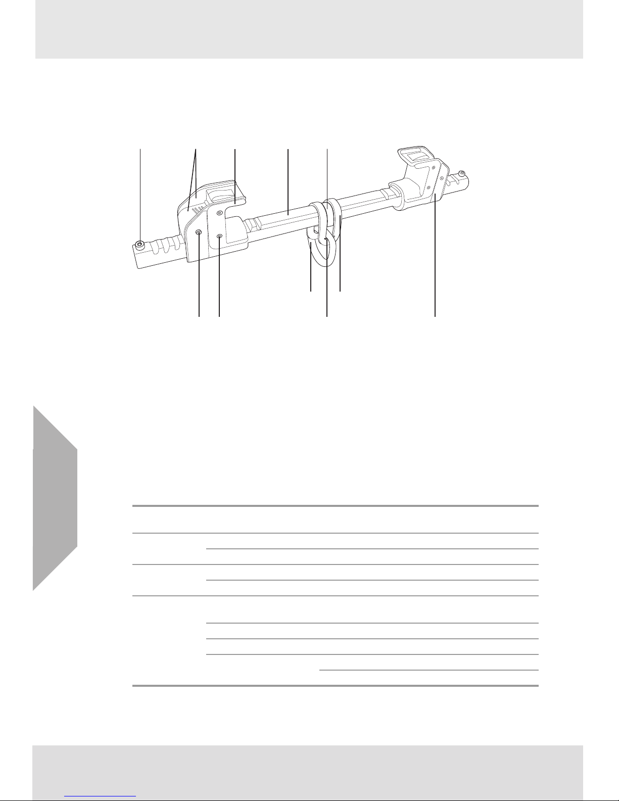
The Workman FP Stryder is an I-beam anchorage connector. The intended purpose of each element
of the Workman FP Stryder is given in sections 2.2 "Attachment Elements" through 2.4 "D-Ring
Connector" below. See inspection diagram for location of elements.
1 Jaw and locking button-2
2 D-ring-1
3 D-ring connector-1
4 Spacer-1
5 Cross bar-1
6 Glide pad-2
7 Barrel screw (-4) and bolt (-6)
8Pin-2
9Screw-2
10 Label-2
11 Load indictor
US
2.1 Specifications
Capacity
Weight
Flange capacity
Materials of
construction
When used as part of a personal fall arrest system, fall arrest forces must not exceed 1800 Ibf (8 kN).
6
400 lbs (182 kg) including weight of the user plus tools, clothing and other userborne objects.
Model 10144431 5 lbs (2.3kg)
Model 10144432 11.9 lbs (5.4 kg)
Model 10144431 4.00 inch (10.2cm) to 13.5 inch (34.3cm)
Model 10144432 14.00 inch (35.6cm) to 23.5 inch (59.7cm)
Housing, Button, Spring,
pin, D-ring connector
Glide pads Teflon impregnated thermal plastic.
D-ring Alloy steel
Crossbar
WORKMAN FP STRYDER
Stainless steel
Model 10144431 Aluminum alloy
Model 10144432 Alloy steel
Page 7

2.2 Attachment Elements
2.2.1 D-Ring
Used for connection to a lanyard element of a personal fall arrest system.
2.2.2 Jaw
Used for connection to the I-beam anchorage.
2.3 Crossbar
The crossbar connects and provides the means for adjustment of the jaws, and anchors the D-ring
connector.
2.4 D-Ring Connector
The D-ring connector connects the D-ring to the crossbar, and provides an integral load indicator.
2.5 Compatibility of System Parts
2.5.1 Compatibility of Components and Subsystems
Workman FP Stryder are designed to be used with other MSA Approved products. Use of the
Workman FP Stryder with products made by others that are not approved in writing by MSA may
adversely affect the functional compatibility between system parts and the safety and reliability of the
complete system.
2.5.2 Compatibility of Connectors
Connectors, such as D-rings, snaphooks, and carabiners must be rated at 5000 Ibf (22.2kN) minimum
capacity. MSA connectors meet this requirement. Connecting hardware must be compatible in size,
shape and strength. Non-compatible connectors may accidentally disengage (“roll out”). Always verify
that the connecting D-ring on the Workman FP Stryder is compatible with the snaphook, or carabiner
of the lanyard subsystem.
2.5.3 Anchorages
The acceptable anchorage for the Workman FP Stryder is a horizontal I-beam. The I-beam must be
configured so that the Workman FP Stryder cannot come off the end of the beam Anchorages for
personal fall arrest systems must either: (a) have a strength capable of supporting and withstanding at
least 5,000 pounds (22.2 kN) in the directions permitted by the system without failure, or (b), must be
certified by a professional engineer as having the required strength for fall arrest or travel restraint, as
applicable. See ANSI Z359.18 for definition of certification. See ANSI Z359.187 for definition of certificate. When more than one personal fall arrest system is attached to an anchorage, the anchorage
strengths set forth in (a) and (b) must be multiplied by the number of systems attached to the
anchorage. This requirement is consistent with OSHA requirements under CFR 1910, subpart F,
Section 1910.66, Appendix C. Do not proceed with installation and user of the anchorage connector if
an assessment of strength cannot be made.
US
WORKMAN FP STRYDER
7
Page 8

3Use
WARNING!
The anchorage to which the Workman FP Stryder is attached must be rated in the direction of
intended use. See section 2.5.3 "Anchorages" for details on anchorage strength and loading
details.
When installing or removing the Workman FP Stryder, limit exposure to fall hazards. A separate
independent fall arrest system may be required.
Ensure that fall clearance is sufficient to meet governing standards or subsystem component
requirements.
Work directly under the anchorage/anchorage connector at all times. A full body harness is the
only acceptable body holding device that can be used in a fall arrest system.
MSA Fall Protection products may not be used while under the influence of drugs or alcohol.
3.1 Planning the Use of Systems
3.1.1 Free Fall Distance, Total Fall Distance and System Elongation
WARNING!
DO NOT exceed the allowable free fall distance or exceed the maximum fall arrest forces as specified
by governing standards or subsystem components.
The capacity of the Workman FP Stryder must be greater or equal the sub-system components.
US
1) Free fall distance. See user instructions and label of compatible deceleration device (i.e. SRL,
lanyard, etc.) for allowable free fall distance.
2) Total fall distance. The sum of the free fall distance and deceleration distance plus a 3 ft (0.92 m)
safety margin.
3) Deceleration distance. Must not exceed 3.5 ft (1.1m).
3.1.2 Pendulum (Swing) Falls
WARNING!
Prevent swing falls and impact with objects in or adjacent to the fall path.
Always remove obstructions below the work area to ensure a clear fall path. Keep work area free from
debris, obstructions, trip hazards, spills or other hazard which could impair the safe operation of the fall
protection system. DO NOT use the Workman FP Stryder unless a qualified person has inspected the
workplace and determined that identified hazards can neither be eliminated nor exposures to them
prevented.
Swing fall hazards must be minimized by anchoring directly above the user’s work space. The force of
striking an object in a pendular motion can cause serious injury. Always minimize swing falls by working
as directly below the anchorage point as possible.
3.1.3 Rescue and Evacuation
The user must have a rescue plan and the means at hand to implement it. The plan must take into
account the equipment and specific training necessary to affect prompt rescue under all foreseeable
conditions. If the rescue be from a confined space, the provisions of OSHA regulation 1910.146 and
ANSI Z117.1 must be taken into account. It is recommended to provide means for user evacuation
without assistance of others. This will usually reduce the time to get to a safe place and reduce or
prevent the risk to rescuers.
8
WORKMAN FP STRYDER
Page 9
3.2 Inspection Before Each Use
Inspect the Workman FP Stryder to verify it is in serviceable condition. Examine entire device for signs
of cracking or deformation. See Section 10 for inspection details. Do not use a Workman FP Stryder if
inspection of it reveals an unsafe condition.
3.3 Making Proper Connections
WARNING!
Do not rely on feel or sound to verify proper snaphook or carabiner engagement. Ensure that gate and
keeper are closed before use.
When connecting the D-ring of the Workman FP Stryder to a lanyard subsystem, be certain accidental
disengagement (“rollout”) cannot occur. Rollout is possible when interference between a snaphook and
the mating connector causes the snaphook’s gate or keeper to accidentally open and release. Rollout
occurs when a snaphook is snapped into an under sized ring such as an eye bolt or other non-compatibly shaped connector. Only self closing, self locking snaphooks and carabiners should be used to
reduce the possibility of rollout when making connections. Do not use snaphooks or connectors that
will not completely close over the attachment object. Do not make knots in a lanyard. Do not hook a
lanyard back onto itself. Snaphooks and carabiners must not be connected to each other. Do not attach
two snaphooks into one D-ring. Always follow the manufacturer’s instructions supplied with each
system component.
3.4 Moving Around the Work Area
The Workman FP Stryder is designed to move along the flange of the I-beam anchorage, following the
user movements. Move around carefully to prevent loss of balance in the event the Workman FP
Stryder binds or contacts an obstacle in the path of movement.
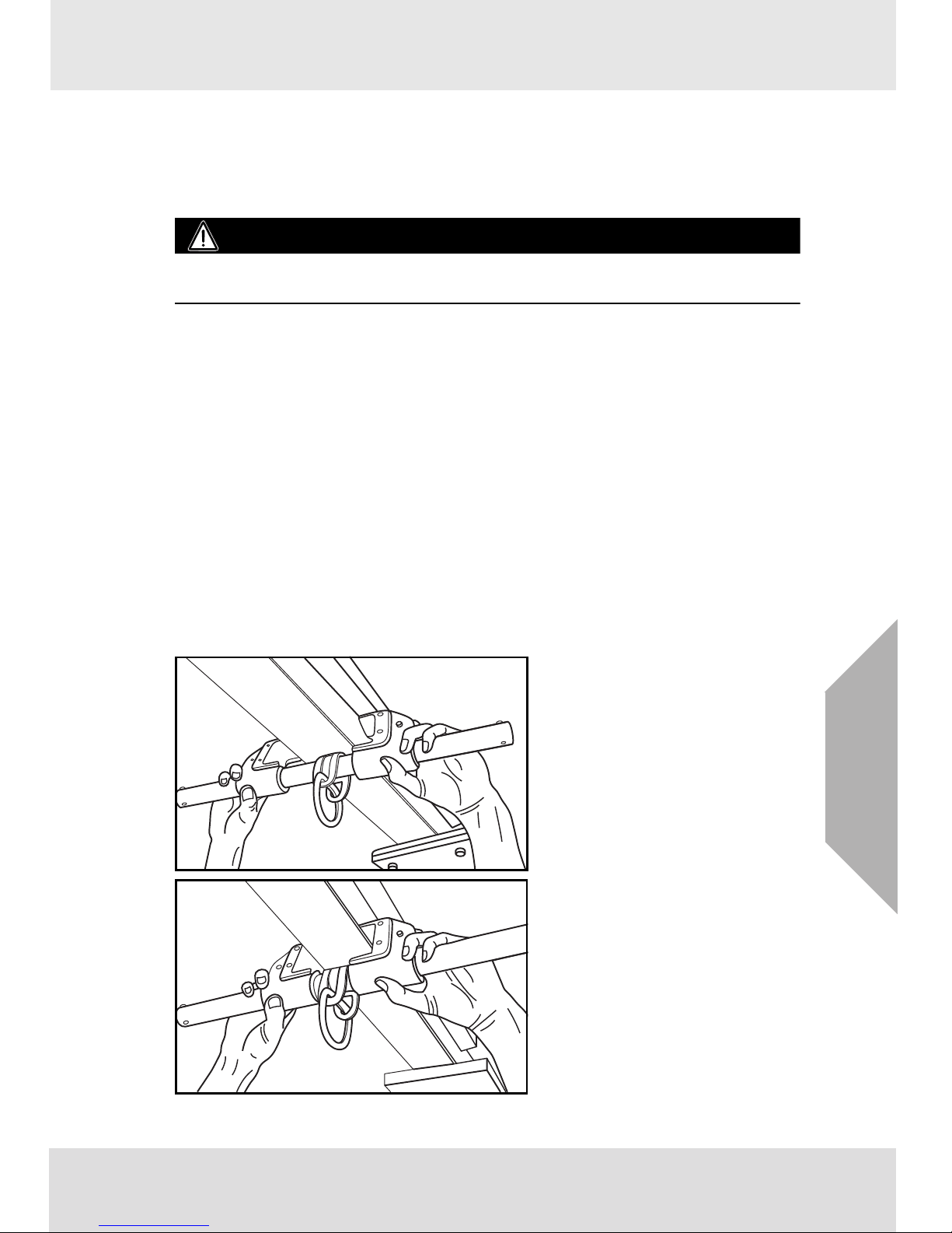
3.5 Connecting the Workman FP Stryder
The Workman FP Stryder may be used in above or below beam applications.
(1) To use the Workman FP Stryder,
depress the buttons to unlock the
jaws and slide the jaws far enough
apart to fit over the flange of the Ibeam anchorage.
(2) Push the jaws together to capture
the flange of the
I-beam. Release the buttons to lock
the jaw to the crossbar. Fine adjust
the jaws to fit, by alternating locking
the jaws in the differently placed slot
in the crossbar.
US
WORKMAN FP STRYDER
9
Page 10
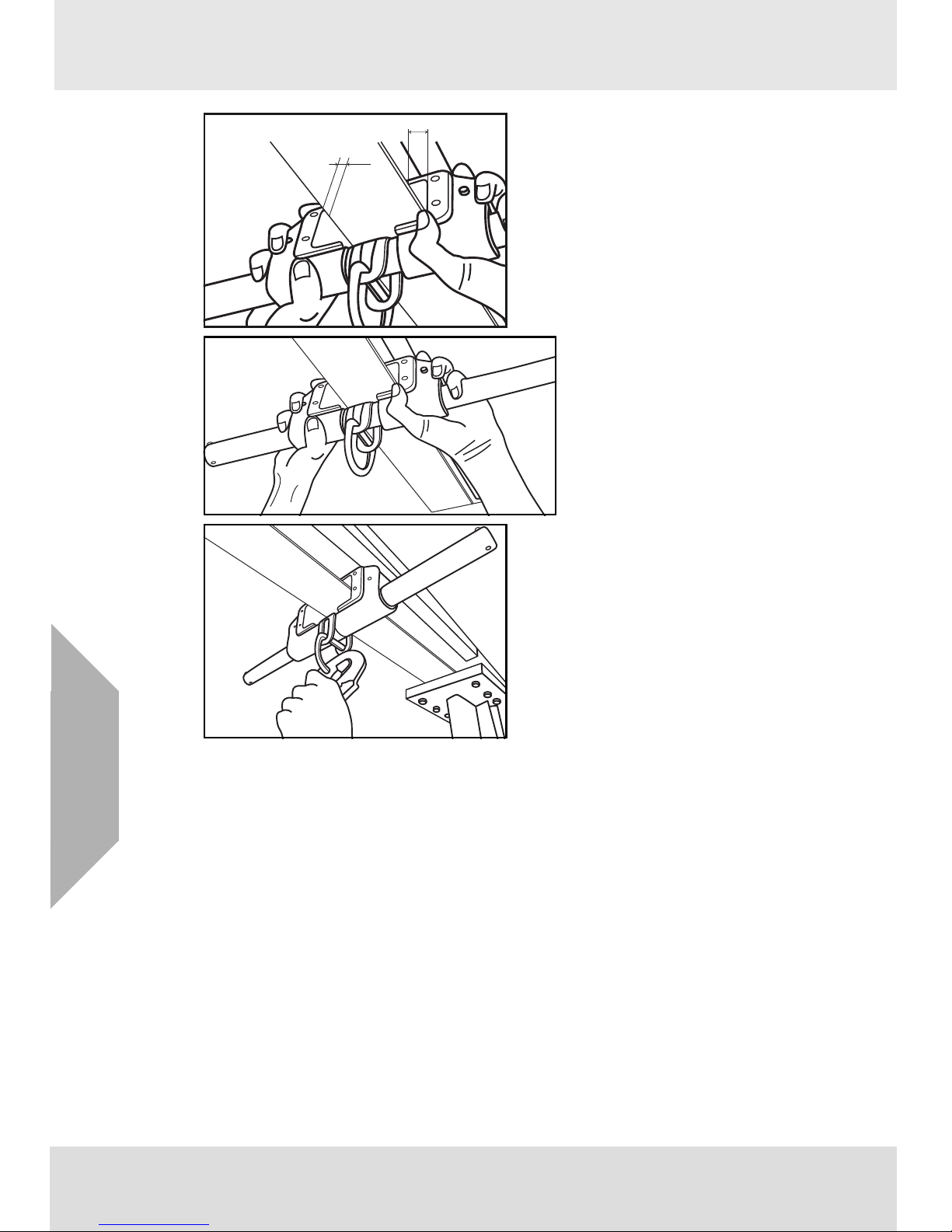
(3) The maximum total clearance
A
B
between the jaws and the flange is
0.5 inch (12.7 mm).
Maximum total clearance = A+B
Maximum total clearance <0.5 inch
(12.7 mm)
(4) Verify the jaws are locked into the
crossbar.
(5) The user can then connect the
snaphook or carabiner of their
lanyard subsystem to the D-ring of
the Workman FP Stryder.
Be certain the snaphook or carabiner gate is completely closed
and locked.
US
10
WORKMAN FP STRYDER
Page 11

4 Cleaning, Maintenance and Storage
4.1 Cleaning Instructions
Use a clean damp (not wet) cloth to remove dirt or contamination which may cause corrosion or
hamper readability of labels. Wipe off any moisture before returning the device to service. Remove any
surface contamination such as concrete, stucco, roofing material, etc., that could accelerate cutting or
abrading of attached components. The frequency of cleaning should be determined by inspection and
by severity of the environment. In highly corrosive environments cleaning should be done every two or
three days. Never use solvents to clean the device as they may damage the plastic components. Don’t
use abrasives to scour the device as they may damage the surface and the labels. To remove oil or
grease, use a mild dishwater detergent on a damp cloth or sponge and follow by repeated swabbing
with a clean cloth to remove all soap residue. Never immerse the product in water or other liquid.
4.2 Storage
Store the device in a clean, dry place indoors. Store the product away from heat and steam and never
allow it to rest for lengthy periods of time on concrete or ash floors as the lime sulfur and ash can cause
corrosion.
4.3 Maintenance
User maintenance consists of cleaning and drying the device and replacement of the glide pad. All
other maintenance or repair/work must be done at the factory or by an authorized person. (Authorization by MSA must be written).
WORKMAN FP STRYDER
US
11
Page 12

US
5Inspection
5.1 Inspection Frequency
WARNING!
If the Workman FP Stryder is damaged or is subjected to fall arrest forces or impact forces, it must be
immediately removed from service and marked as "UNUSABLE" until it has been destroyed.
The Workman FP Stryder must be inspected by the user before each use. Additionally, the Workman
FP Stryder must be inspected by a competent person other than the user at intervals of no more than
six months. The competent person inspection is referred to as Formal Inspection. An inspection log
must be filled out during the Formal Inspection, see section 5.4 "Inspection Log". In addition, the
inspection log on the Workman FP Stryder label must be marked or punched to indicate when the last
Formal Inspection occurred.
The program administrator shall maintain documentation of equipment inspections. This documentation shall include, at a minimum, the identity of the equipment, inspection date, name of the competent
or qualified person conducting the inspection and the result of that inspection.
The program administrator shall sett inspection criteria for the equipment. Such criteria shall equal or
exceed the most restrictive of the criteria established by the ANSI Z359.18 standard or the manufacturer‘s user instructions. Keep inspection criteria current in relationship to changing patterns or conditions of use.
5.2 Procedure for Inspection
Perform the following steps in sequence. If in doubt about any inspection point, consult MSA or a
competent person who is qualified to perform a Formal Inspection as described in section 11.
(1) Inspect the Workman FP Stryder labels to verify that they are present and legible. See Section 6
"Markings And Labels" for the specific labels that should be present and the information
contained thereon. Check the Formal Inspection Log to be sure a Formal Inspection has been
performed within the last six months. If the Log does not indicate that a Formal Inspection has
been performed within the last six months, or if any labels are missing or illegible, remove the
device from use and mark it as “UNUSABLE” until a Formal Inspection is performed by a competent person.
(2) Check the auto close action of the button. Depress button with thumb, and ensure auto closing.
If button fails these functional tests, return to maintain from service.
(3) Check for structural defects and corrosion. Verify that are no missing, loose screw or altered
parts; that there are no cracks, deformations, or excessive corrosion.
(4) Inspect the D-ring for deformation, damage, fractures, cracks, corrosion, deep pitting, burrs,
sharp edges, cuts, deep nicks, evidence of excessive heat or chemical exposures. Check the
pin with screw for no deformation, fractures, cracks, corrosion, pitting and nicks. Verify the screw
in the pin tightly. If the screws which connected with pins are loose, remove the device from use
and make It “UNUSABLE”. Check the entire assembly for evidence of inadequate maintenance
of equipment, alteration, excessive wear, or any condition that calls to question the suitability of
the equipment for its intended purpose.
(5) Inspect the load indicating D-ring connector for activation. If the device has been exposed to a
fall arrest force the window will be deformed, remove the device from use and make it “UNUSABLE”.
(6) Inspect each component and subsystem of the complete system in accordance with the associ-
ated manufacturer’s instructions. See section 3.1 "Planning the Use of Systems" for a description of the makeup of the different types of subsystem and systems.
12
WORKMAN FP STRYDER
Page 13

5.3 Corrective Action
WARNING!
Unauthorized alterations, relocations or additions to the anchorage connector are not permitted.
Only MSA or persons or entities with written authorization from the manufacturer may make repairs to
the Workman FP Stryder. No unauthorized repairs, modifications, alterations, relocations, and/or additions are permitted.
When inspection reveals sign of inadequate maintenance, the Workman FP Stryder must be immediately removed from service and marked as “UNUSABLE” until destroyed or subjected to corrective
maintenance. Defects, damage, excessive wear, malfunction and aging are generally not repairable.
If detected immediately remove the Workman FP Stryder from use and mark it as “UNUSABLE” until
destroyed. For final disposition, submit the Workman FP Stryder to a competent person who is authorized to perform Formal Inspection. If there is any question as to reliability, contact MSA, or a service
center authorized in writing by MSA, before further use of the device.
5.4 Inspection Log
Model No.: Inspector:
Serial No.:
Date Made: Disposition:
Comments:
Inspection
Date:
WORKMAN FP STRYDER
US
13
Page 14
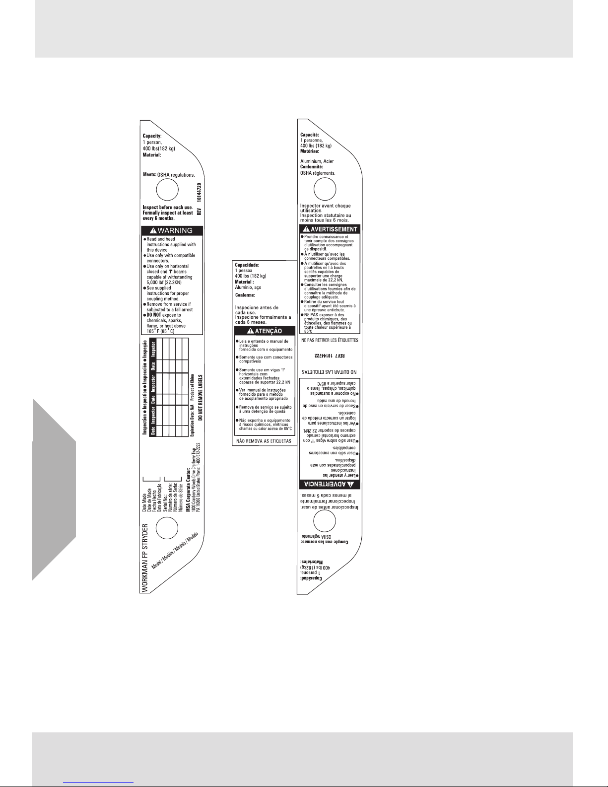
6 Markings And Labels
8
regulações OSHA
(10144431)
Aço (10144432)
Acier 10144432
10144431
Acero (10144432)
Aluminio, Acero (10144432)
Steel (10144432)
Aluminium, Steel (10144431)
The labels must be present, legible and securely attached to the Workman FP Stryder. The labels are
located on the sides of the jaws.
US
14
WORKMAN FP STRYDER
Page 15

WORKMAN FP STRYDER
15
US
Page 16

For local MSA contacts, please visit us at MSAsafety.com
Because every life has a purpose...
Page 17

MSAsafety.com
Model Number / Número de modelo /
Numéro de modèle / Número do modelo:
10144431
□ 10144432 □
Instrucciones para el usuario
Workman FP Stryder
TM
Anclaje para viga
N.º de referencia: 10145808/03
Espec. de impresión: 10000005389 (F)
CR 800000030551
Page 18

ADVERTENCIA!
Conforme a la normativa nacional y a las legislaciones estatales, provinciales y federales, el
usuario debe recibir formación antes de utilizar este producto. Utilice este manual como parte
de un programa de formación sobre la seguridad del usuario que sea adecuado para el puesto
de trabajo del usuario. Es necesario proporcionar estas instrucciones a los usuarios antes del
uso del producto y conservarlas a mano para que el usuario pueda consultarlas. El usuario
debe leer y comprender (o deben explicarle) todas las instrucciones, etiquetas, marcados y
advertencias suministrados con este producto y con los productos que se vayan a utilizar en
combinación con el mismo. EL INCUMPLIMIENTO DE ESTA RECOMENDACIÓN PUEDE
CONLLEVAR LESIONES GRAVES O LETALES.
1000 Cranberry Woods Drive
Cranberry Township, PA 16066
EE. UU.
Teléfono: 1-800-MSA-2222
Fax: 1-800-967-0398
Para consultar sus contactos locales de MSA, visite nuestra página web www.MSAsafety.com
©
MSA 2018. Todos los derechos reservados
Page 19

WORKMAN FP STRYDER
3
ES
1 Normativas de seguridad . . . . . . . . . . . . . . . . . . . . . . . . . . . . . . . . 4
1.1 Uso correcto . . . . . . . . . . . . . . . . . . . . . . . . . . . . . . . . . . . . . . 4
1.2 Conformidad . . . . . . . . . . . . . . . . . . . . . . . . . . . . . . . . . . . . . . 4
1.3 Limitaciones de uso . . . . . . . . . . . . . . . . . . . . . . . . . . . . . . . . . 4
1.4 Medidas preventivas y de seguridad a adoptar . . . . . . . . . . . . 4
1.5 Garantía . . . . . . . . . . . . . . . . . . . . . . . . . . . . . . . . . . . . . . . . . . 5
2 Descripción . . . . . . . . . . . . . . . . . . . . . . . . . . . . . . . . . . . . . . . . . . . 6
2.1 Especificaciones . . . . . . . . . . . . . . . . . . . . . . . . . . . . . . . . . . . 6
2.2 Elementos de acoplamiento . . . . . . . . . . . . . . . . . . . . . . . . . . 7
2.3 Cruceta . . . . . . . . . . . . . . . . . . . . . . . . . . . . . . . . . . . . . . . . . . 7
2.4 Conector de la argolla en D . . . . . . . . . . . . . . . . . . . . . . . . . . . 7
2.5 Compatibilidad de las piezas del sistema . . . . . . . . . . . . . . . . 7
3 Uso . . . . . . . . . . . . . . . . . . . . . . . . . . . . . . . . . . . . . . . . . . . . . . . . . . 8
3.1 Planificación del uso de los sistemas . . . . . . . . . . . . . . . . . . . 8
3.2 Inspección antes de cada uso . . . . . . . . . . . . . . . . . . . . . . . . . 9
3.3 Realización de conexiones correctas . . . . . . . . . . . . . . . . . . . 9
3.4 Desplazamiento por el área de trabajo . . . . . . . . . . . . . . . . . . 9
3.5 Conexión del Workman FP Stryder . . . . . . . . . . . . . . . . . . . . . 9
4 Limpieza, mantenimiento y almacenamiento . . . . . . . . . . . . . . . 11
4.1 Instrucciones de limpieza . . . . . . . . . . . . . . . . . . . . . . . . . . . 11
4.2 Almacenamiento . . . . . . . . . . . . . . . . . . . . . . . . . . . . . . . . . . 11
4.3 Mantenimiento . . . . . . . . . . . . . . . . . . . . . . . . . . . . . . . . . . . . 11
5 Inspección . . . . . . . . . . . . . . . . . . . . . . . . . . . . . . . . . . . . . . . . . . . 12
5.1 Frecuencia de inspección . . . . . . . . . . . . . . . . . . . . . . . . . . . 12
5.2 Procedimiento para la inspección . . . . . . . . . . . . . . . . . . . . . 12
5.3 Acción correctiva . . . . . . . . . . . . . . . . . . . . . . . . . . . . . . . . . . 13
5.4 Registro de inspección . . . . . . . . . . . . . . . . . . . . . . . . . . . . . 13
6 Marcados y etiquetas . . . . . . . . . . . . . . . . . . . . . . . . . . . . . . . . . . 14
Page 20

ES
WORKMAN FP STRYDER
4
1 Normativas de seguridad
1.1 Uso correcto
El Workman FP Stryder está diseñado para ser utilizado por una persona durante trabajos en altura.
El Workman FP Stryder une al usuario con un punto de anclaje de una viga en I. Permite al trabajador
utilizar una viga en I disponible como anclaje temporal sin necesidad de perforar ni de acoplar anclajes
de forma permanente. Se mueve junto con el trabajador permitiendo un amarre continuo.
Si se hace caso omiso de cualquiera de las advertencias de las presentes instrucciones para el
usuario, podrían sufrirse lesiones personales graves o letales.
1.2 Conformidad
• ANSI Z359.18, tipo A; requisitos OSHA
• El producto puede cumplir las normas indicadas. Consulte en la etiqueta del producto las
notificaciones específicas sobre la conformidad. '
• Los conectores de anclaje etiquetados con ANSI Z359.18 han sido probados de conformidad con
los requisitos de ANSI/ASSE Z359.7.
NOTA: la conformidad y las pruebas según ANSI cubren únicamente el hardware y no abarcan el
anclaje ni la superficie a la que está fijado el conector de anclaje.
1.3 Limitaciones de uso
Es preciso tener en cuenta y planificar las siguientes limitaciones de aplicación antes de utilizar el
Workman FP Stryder.
1.3.1 Limitaciones físicas
Las personas que sufran enfermedades musculares, del esqueleto o físicas deben consultar a un
médico antes de utilizar el equipo. Las mujeres embarazadas y las personas menores de edad no
deben utilizar nunca el Workman FP Stryder. Cuanta más edad tenga el usuario y cuanto peor sea su
estado físico, mayor será la probabilidad de que se reduzca su capacidad de resistir cargas de impacto
durante la retención de una caída o una suspensión prolongada. Consulte a un médico si tuviera
alguna duda sobre la capacidad física de utilizar con seguridad este producto como retención de una
caída o para aplicaciones en suspensión.
1.3.2 Peligros
Los peligros químicos, el calor y la corrosión pueden provocar daños en el Workman FP Stryder. En
este tipo de entornos se precisan inspecciones más frecuentes. No utilice el dispositivo en entornos
con temperaturas superiores a 85 ºC (185 ºF).
Lo siguiente puede provocar daños en el producto:
• NO utilice el dispositivo en los casos en los que elemento de amarre o el amortiguador de
impactos puedan verse expuestos a bordes afilados o abrasivos, a metal expandido cizallado o a
acero de corte de bastidor. Los bordes afilados pueden cortar un elemento de amarre o un
amortiguador de impactos durante una caída. Cubra todos los bordes afilados o abrasivos con
acolchado o revestimiento antes de trabajar por encima del borde.
• No instale el equipo donde este pueda estar sometido a peligros eléctricos o máquinas en
movimiento.
• No deje el Workman FP Stryder montado en entornos en los que pueda sufrir daños o
deteriorarse. Consulte en los apartados 4.3 "Mantenimiento" y 5 "Inspección" la información
detallada sobre el cuidado y la inspección. No deje cargas desatendidas en el Workman FP
Stryder.
• Evite utilizar el Workman FP Stryder junto a máquinas en movimiento, peligros eléctricos o
superficies abrasivas, así como en presencia de un calor excesivo, llama abierta o metal fundido.
• No utilice el Workman FP Stryder cerca de equipos bajo tensión o en lugares donde pueda entrar
en contacto con líneas eléctricas de alta tensión. Los componentes metálicos del Workman FP
Stryder pueden conducir corriente eléctrica, lo que podría provocar una descarga eléctrica o
electrocución.
Page 21

WORKMAN FP STRYDER
5
ES
• Elimine de la superficie cualquier suciedad, p. ej., hormigón, yeso, material de cubierta, etc. que
pudiera acelerar el corte o la abrasión de los componentes acoplados.
• Está prohibido realizar alteraciones, reubicaciones o anexos no autorizados en el conector de
anclaje.
1.4 Medidas preventivas y de seguridad a adoptar
• Es responsabilidad del comprador del Workman FP Stryder asegurarse de que los usuarios se
familiaricen con estas instrucciones para el usuario y de que reciban formación por parte de una
persona competente. Durante la formación, el aprendiz no debe verse expuesto a peligros de
forma indebida. MSA ofrece programas de formación. Póngase en contacto con la empresa para
recibir información sobre la formación.
• NO altere el equipo ni lo someta intencionadamente a un uso indebido. NO utilice un equipo de
protección anticaídas para fines distintos a aquellos para los que ha sido concebido. NO utilice un
equipo de protección anticaídas para arrastrar, elevar o manipular materiales.
• Si un EPI se volviera a vender, deberán proporcionarse instrucciones de uso, mantenimiento e
inspección periódica en el idioma del país de destino.
• Utilice el Workman FP Stryder únicamente en vigas horizontales.
1.5 Garantía
Garantía expresa – MSA garantiza que el producto suministrado estará exento de defectos
mecánicos y de fallos de funcionamiento durante un período de un (1) año a partir del primer uso o
de dieciocho (18) meses a partir de la fecha de envío, cualquiera que se produzca antes, siempre y
cuando se mantenga y utilice conforme a las instrucciones y/o recomendaciones de MSA. Los
repuestos y reparaciones cuentan con una garantía de noventa (90) días a partir de la fecha de
reparación del producto o la venta del repuesto, cualquiera que se produzca antes. MSA queda
exenta de toda obligación contraída con esta garantía si personas distintas a las de su propio
personal o a las del servicio autorizado realizasen reparaciones o modificaciones, o si se reclama la
garantía por mal uso del producto. Ningún agente, empleado o representante de MSA puede
vincular a MSA a ninguna afirmación, representación o modificación de la garantía relativa a los
productos vendidos con este contrato. MSA no ofrece garantía alguna por los componentes o
accesorios que no hayan sido fabricados por MSA, aunque transferirá al comprador todas las
garantías del fabricante de dichos componentes. ESTA GARANTÍA SUSTITUYE A CUALQUIER
OTRA GARANTÍA, YA SEA EXPRESA, IMPLÍCITA U OBLIGATORIA, Y SE LIMITA
ESTRICTAMENTE A LOS TÉRMINOS DE ESTE DOCUMENTO. MSA RECHAZA
ESPECÍFICAMENTE TODA RESPONSABILIDAD DE CUALQUIER GARANTÍA DE
COMERCIABILIDAD O DE IDONEIDAD PARA UN FIN DETERMINADO.
Recurso exclusivo - Se acuerda de forma expresa que el recurso único y exclusivo del comprador,
por incumplimiento de la anterior garantía, por cualquier conducta dolosa de MSA o por cualquier
otra causa de acción, será la reparación y/o cambio a criterio de MSA, de cualquier equipo o pieza
del mismo que, tras haber sido examinado por parte de MSA, se haya probado como defectuoso.
El reemplazo de equipos y/o piezas se realizará sin costo alguno para el comprador, FOB en el
destino indicado por el comprador. El incumplimiento de MSA de reparar satisfactoriamente
cualquier producto no conforme no será causa de la pérdida del propósito esencial del recurso aquí
establecido.
Exclusión de daños indirectos - El comprador entiende y acepta específicamente que, bajo
ninguna circunstancia, MSA será responsable ante el comprador por los daños o las pérdidas
económicas, especiales, incidentales o resultantes de ninguna clase, incluida pero sin limitarse a
ella, la pérdida de beneficios anticipados y cualquier otra pérdida causada por la falta de
operatividad de los productos. Esta exclusión se aplica a las reclamaciones por incumplimiento de
la garantía, conducta dolosa o cualquier otra causa de acción contra MSA.
Para obtener información adicional, póngase en contacto con el departamento de atención al cliente
en el 1-800-MSA-2222 (1-800-672-2222).
Page 22

ES
WORKMAN FP STRYDER
6
2 Descripción
El Workman FP Stryder es un conector de anclaje para vigas en I. El propósito previsto de cada uno
de los elementos que conforman el Workman FP Stryder se indica a continuación en los apartados del
2.2 "Elementos de acoplamiento" al 2.4 "Conector de la argolla en D". Consulte en el diagrama de
inspección la ubicación de los elementos.
2.1 Especificaciones
En caso de utilizarse como parte de un sistema anticaídas personal, las fuerzas de parada en la caída
no deben superar los 8 kN (1800 Ibf).
1 Mordaza y botón de bloqueo-2
2 Argolla en D-1
3 Conector de la argolla en D-1
4 Separador-1
5 Cruceta-1
6 Almohadilla de deslizamiento-2
7 Tornillo de cilindro (-4) y perno (-6)
8 Pasador-2
9 Tornillo-2
10 Etiqueta-2
11 Indicador de carga
8 7
1
2
11
3
4
6
10
9 5
Capacidad
182 kg (400 lbs) incluido el peso del usuario más herramientas, ropa y otros
objetos transportados por el usuario.
Peso
Modelo 10144431 2,3 kg (5 lbs)
Modelo 10144432 5,4 kg (11,9 lbs)
Capacidad del
borde
Modelo 10144431 10,2 cm (4,00 pulg.) a 34,3 cm (13,5 pulg.)
Modelo 10144432 35,6 cm (14,00 pulg.) a 59,7 cm (23,5 pulg.)
Materiales de
construcción
Carcasa, botón, resorte, pasador,
conector de la argolla en D
Acero inoxidable
Almohadillas de deslizamiento Termoplástico impregnado con teflón
Argolla en D Aleación de acero
Cruceta
Modelo 10144431 Aleación de aluminio
Modelo 10144432 Aleación de acero
Page 23

WORKMAN FP STRYDER
7
ES
2.2 Elementos de acoplamiento
2.2.1 Argolla en D
Se utiliza para la conexión a un elemento de amarre de un sistema anticaídas personal.
2.2.2 Mordaza
Se emplea para la conexión al anclaje de la viga en I.
2.3 Cruceta
La cruceta conecta y permite ajustar las mordazas, a la vez que ancla el conector de la argolla en D.
2.4 Conector de la argolla en D
El conector de la argolla en D conecta la argolla en D a la cruceta y proporciona un indicador de carga
integral.
2.5 Compatibilidad de las piezas del sistema
2.5.1 Compatibilidad de componentes y subsistemas
Los Workman FP Stryder están diseñados para ser utilizados con otros productos autorizados por
MSA. El uso del Workman FP Stryder con productos de otros fabricantes que no hayan sido
autorizados por escrito por parte de MSA puede afectar negativamente a la compatibilidad funcional
entre los componentes del sistema y a la seguridad y la fiabilidad del sistema completo.
2.5.2 Compatibilidad de conectores
Los conectores, como pueden ser las argollas en D, los ganchos de seguridad y los mosquetones,
deben presentar una capacidad mínima de 22,2 kN (5000 lbf). Los conectores de MSA cumplen este
requisito. Los dispositivos de conexión deben ser compatibles en tamaño, forma y resistencia. Los
conectores no compatibles pueden desengancharse accidentalmente ("separación accidental").
Compruebe siempre que la argolla en D de conexión del Workman FP Stryder es compatible con el
gancho de seguridad o el mosquetón del subsistema del elemento de amarre.
2.5.3 Anclajes
El anclaje aceptable para el Workman FP Stryder es una viga en I horizontal. La viga en I debe estar
configurada de modo que el Workman FP Stryder no pueda salir del extremo de la viga. Los anclajes
para sistemas anticaídas personales deben: (a) presentar una resistencia capaz de soportar y
aguantar al menos 22,2 kN (5000 lbs) en las direcciones permitidas por el sistema sin fallar, o (b) estar
certificados por un ingeniero profesional que asegure que presentan la resistencia necesaria para la
retención de caídas o la contención de desplazamiento según sea aplicable. Consulte en ANSI
Z359.18 la definición de la certificación. Consulte en ANSI Z359.187 la definición del certificado. Si se
acopla más de un sistema anticaídas personal a un anclaje, las resistencias de anclaje establecidas
en (a) y en (b) más arriba deberán multiplicarse por el número de sistemas anticaídas personales
acoplados. Este requisito satisface las estipulaciones OSHA de CFR 1910, subparte F, sección
1910.66, anexo C. No realice el montaje ni utilice el conector de anclaje en caso de no poderse evaluar
la resistencia.
Page 24

ES
WORKMAN FP STRYDER
8
3 Uso
ADVERTENCIA!
El anclaje al que está acoplado el Workman FP Stryder debe estar clasificado para la dirección
de uso previsto. Consulte en el apartado 2.5.3 "Anclajes" la información sobre la resistencia de
anclaje y la carga.
Al montar o retirar el Workman FP Stryder, limite los riesgos de sufrir caídas. Puede ser necesario
utilizar un sistema anticaídas independiente.
Asegúrese de que la distancia de caída es suficiente para cumplir las normativas en vigor o los
requisitos de los componentes del subsistema.
Trabaje directamente bajo el anclaje/conector de anclaje en todo momento. Un arnés anticaídas
es el único dispositivo de sujeción corporal admitido para el uso en un sistema anticaídas.
Los productos de protección anticaídas de MSA no pueden utilizarse bajo los efectos de las
drogas o del alcohol.
3.1 Planificación del uso de los sistemas
3.1.1 Distancia de caída libre, distancia de caída total y alargamiento del sistema
ADVERTENCIA!
NO exceda la distancia de caída libre permitida ni las fuerzas máximas de parada en la caída
especificadas por las normativas en vigor o los componentes del subsistema.
La capacidad del Workman FP Stryder debe ser igual o mayor que la de los componentes del
subsistema.
1) Distancia de caída libre. Consulte en las instrucciones para el usuario y en la etiqueta del
dispositivo de deceleración compatible (p. ej., SRL, elemento de amarre, etc.) la distancia de
caída libre permitida.
2) Distancia de caída total. La suma de la distancia de caída libre y de la distancia de deceleración
más un margen de seguridad de 0,92 m (3 ft).
3) Distancia de deceleración. No debe superar los 1,1 m (3,5 ft).
3.1.2 Caídas tipo péndulo (con balanceo)
ADVERTENCIA!
Evite las caídas con balanceo y los impactos contra objetos situados en la trayectoria de caída
o en sus inmediaciones.
Es necesario eliminar cualquier obstáculo situado debajo del área de trabajo con el fin de garantizar
una trayectoria de caída despejada. Mantenga la zona de trabajo libre de suciedad, obstáculos,
peligros de tropiezo, derrames u otros peligros que pudieran mermar el funcionamiento seguro del
sistema de protección anticaídas. NO utilice el Workman FP Stryder a no ser que una persona
cualificada haya inspeccionado el lugar de trabajo y haya determinado que los peligros identificados
no pueden eliminarse o que no es posible evitar la exposición a los mismos.
Minimice el peligro de caída por balanceo realizando el anclaje directamente por encima de la posición
de trabajo del usuario. La fuerza al golpear un objeto en movimiento pendular puede provocar lesiones
de gravedad. Minimice siempre las caídas con balanceo trabajando lo más directamente posible
debajo del punto de anclaje.
Page 25

WORKMAN FP STRYDER
9
ES
3.1.3 Rescate y evacuación
El usuario debe disponer de un plan de rescate y de los medios necesarios para implementarlo. El
plan debe tener en cuenta los equipos y la formación específica necesarios para llevar a cabo un
rescate inmediato en todas las condiciones predecibles. Si el rescate tiene lugar desde un espacio
confinado, deberán tenerse en cuenta las disposiciones de la regulación OSHA 1910.146 y ANSI
Z117.1. Se recomienda poner a disposición medios para la evacuación de usuarios sin la asistencia
de terceras personas. Por lo general, esto disminuirá el tiempo necesario para llegar a un lugar seguro
y reducirá o evitará el riesgo para las personas encargadas del rescate.
3.2 Inspección antes de cada uso
Inspeccione el Workman FP Stryder para verificar que se encuentra en perfecto estado operativo.
Examine el dispositivo completo para descartar grietas o deformación. Consulte en el apartado 10 la
información detallada sobre la inspección. No utilice un Workman FP Stryder si la inspección revela
un estado no seguro.
3.3 Realización de conexiones correctas
ADVERTENCIA!
Para comprobar el acoplamiento correcto de los ganchos de seguridad o de los mosquetones, no
confíe en el tacto o el sonido. Asegúrese de que el pestillo y el retenedor estén cerrados antes del uso.
Al conectar la argolla en D del Workman FP Stryder a un subsistema de elemento de amarre,
asegúrese de que no puede desengancharse accidentalmente ("separación accidental"). Puede
producirse una separación de este tipo si interferencias entre un gancho de seguridad y el conector
de acoplamiento hacen que el pestillo o el retenedor del gancho de seguridad se abran y liberen
accidentalmente. Se produce una separación accidental cuando un gancho de seguridad se engancha
en una argolla sin las dimensiones suficientes como puede ser un cáncamo u otro conector con una
forma no compatible. Al realizar las conexiones, utilice únicamente ganchos de seguridad y
mosquetones con autoenclavimiento y cierre automático para recudir la posibilidad de que se
produzca una separación accidental. No utilice ganchos de seguridad o conectores que no se cierren
completamente sobre el objeto acoplado. No realice nudos en los elementos de amarre. No enganche
un elemento de amarre a sí mismo. Los ganchos de seguridad y los mosquetones no deben
conectarse entre sí. No acople dos ganchos de seguridad a una misma argolla en D. Siga siempre las
instrucciones del fabricante suministradas con cada componente del sistema.
3.4 Desplazamiento por el área de trabajo
El Workman FP Stryder está diseñado para moverse por el borde del anclaje de la viga en I siguiendo
los movimientos del usuario. Muévase con cuidado para evitar perder el equilibrio en caso de que el
Workman FP Stryder se enganche o entre en contacto con un obstáculo en la trayectoria de
movimiento.
3.5 Conexión del Workman FP Stryder
El Workman FP Stryder puede utilizarse por encima o debajo de vigas.
(1) Para utilizar el Workman FP Stryder,
pulse los botones para desbloquear
las mordazas y deslice las mordazas
alejándolas lo suficiente para que se
ajusten sobre el borde del anclaje de
la viga en I.
Page 26

ES
WORKMAN FP STRYDER
10
(2) Comprima las mordazas para
atrapar el borde de la viga en I.
Suelte los botones para bloquear la
mordaza en la cruceta. Ajuste con
precisión las mordazas
bloqueándolas de forma alternativa
en la ranura situada en otra posición
de la cruceta.
(3) La distancia total máxima entre las
mordazas y el borde es de 12,7 mm
(0,5 pulg.).
Distancia total máxima = A+B
Distancia total máxima < 12,7 mm
(0,5 pulg.)
(4) Compruebe que las mordazas están
bloqueadas en la cruceta.
(5) A continuación, el usuario puede
conectar el gancho de seguridad o el
mosquetón del subsistema del
elemento de amarre a la argolla en D
del Workman FP Stryder.
Asegúrese de que el pestillo del
gancho de seguridad o del
mosquetón esté completamente
cerrado y bloqueado.
A
B
Page 27

WORKMAN FP STRYDER
11
ES
4 Limpieza, mantenimiento y almacenamiento
4.1 Instrucciones de limpieza
Utilice un paño húmedo (no mojado) para eliminar la suciedad o la contaminación que podrían
provocar corrosión o reducir la legibilidad de las etiquetas. Seque toda humedad con un paño antes
de volver a poner en servicio el dispositivo. Elimine de la superficie cualquier suciedad, p. ej.,
hormigón, yeso, material de cubierta, etc. que pudiera acelerar el corte o la abrasión de los
componentes acoplados. La frecuencia de limpieza debe estipularse mediante una inspección y
teniendo en cuenta las condiciones del entorno. En entornos muy corrosivos debería efectuarse una
limpieza cada dos o tres días. No utilice nunca disolventes para limpiar el dispositivo puesto que los
componentes de plástico podrían resultar dañados. No utilice abrasivos para limpiar el dispositivo ya
que podrían dañar la superficie y las etiquetas. Para eliminar el aceite o la grasa, utilice un lavavajillas
suave con un paño húmedo o una esponja y, seguidamente, emplee un paño limpio para eliminar todo
residuo de jabón. No sumerja nunca el producto en agua u otros líquidos.
4.2 Almacenamiento
Almacene el dispositivo es una estancia interior limpia y seca. Almacene el producto alejado del calor
y del vapor y no permita que permanezca durante periodos de tiempo prolongados sobre suelos de
hormigón o con ceniza ya que el polisulfuro de calcio y la ceniza pueden provocar corrosión.
4.3 Mantenimiento
El mantenimiento que debe efectuar el usuario consiste en limpiar y secar el dispositivo y en sustituir
la almohadilla de deslizamiento. El mantenimiento o las reparaciones y trabajos restantes deben
realizarse en fábrica o por una persona autorizada. (MSA debe otorgar la autorización por escrito).
Page 28

ES
WORKMAN FP STRYDER
12
5 Inspección
5.1 Frecuencia de inspección
ADVERTENCIA!
Si el Workman FP Stryder estuviera dañado o si se hubiera visto expuesto a fuerzas de parada en la
caída o a fuerzas de impacto, deberá ponerse fuera de servicio de inmediato y marcarse como
"INSERVIBLE" hasta destruirse.
El usuario debe inspeccionar el Workman FP Stryder antes de cada uso. Además, el Workman FP
Stryder debe inspeccionarse por una persona competente diferente al usuario en intervalos no
superiores a seis meses. La inspección efectuada por una persona competente se conoce como
inspección oficial. Es preciso cumplimentar un registro de inspección durante la inspección oficial,
véase el apartado 5.4 "Registro de inspección". Asimismo, es necesario marcar o perforar el registro
de inspección de la etiqueta del Workman FP Stryder para indicar cuándo se ha realizado la última
inspección oficial.
El administrador de programas debe llevar una documentación de las inspecciones de los equipos.
Dicha documentación debe incluir al menos la identidad del equipo, la fecha de inspección, el nombre
de la persona competente o cualificada que ha realizado la inspección y el resultado de la inspección.
El administrador de programas debe estipular los criterios de inspección para el equipo. Dichos
criterios deben ser iguales o superar los criterios más restrictivos establecidos por la norma ANSI
Z359.18 o por las instrucciones para el usuario del fabricante. Mantenga los criterios de inspección
acordes al cambio de los patrones o de las condiciones de uso.
5.2 Procedimiento para la inspección
Lleve a cabo los siguientes pasos en orden. Si tuviera alguna duda respecto a algún punto de la
inspección, consulte a MSA o a una persona competente cualificada para efectuar una inspección
oficial según se describe en el apartado 11.
(1) Inspeccione las etiquetas del Workman FP Stryder para verificar que están disponibles y
legibles. Consulte en el apartado 6 "Marcados y etiquetas" las etiquetas específicas deben estar
presentes así como la información que deben incluir. Consulte el archivo de inspección oficial
para asegurarse de que se ha efectuado una inspección oficial durante los últimos seis meses.
Si el registro no muestra que se ha realizado una inspección oficial durante los últimos seis
meses o si faltara alguna etiqueta o estuviera ilegible, retire el dispositivo del servicio y
márquelo como "INUTILIZABLE" hasta que una persona competente lleve a cabo una
inspección oficial.
(2) Compruebe la acción de cierre automático del botón. Pulse el botón con el pulgar y asegúrese
de que cierra automáticamente. Si el botón no superara estas pruebas funcionales, devuelva el
dispositivo para que el servicio técnico realice el mantenimiento.
(3) Descarte la presencia de defectos estructurales y de corrosión. Compruebe que no falten
tornillos y que no estén flojos, que no haya componentes alterados, grietas, deformaciones o
una corrosión excesiva.
(4) Inspeccione la argolla en D para descartar deformaciones, daños, fisuras, grietas, corrosión,
picaduras profundas, rebabas, bordes afilados, cortes, incisiones o signos de una exposición a
un calor excesivo o a productos químicos. Compruebe el pasador con tornillo para descartar la
presencia de deformación, fisuras, grietas, corrosión, picaduras e incisiones. Verifique que el
tornillo se ajusta firmemente en el pasador. Si los tornillos unidos a los pasadores están sueltos,
retire el dispositivo del servicio y márquelo como "INUTILIZABLE". Compruebe el conjunto
completo para descartar evidencias de un mantenimiento inadecuado del equipo, alteraciones,
un desgaste excesivo o cualquier estado que ponga en duda la idoneidad del equipo para su fin
previsto.
(5) Inspeccione una posible activación en el indicador de carga del conector de la argolla en D. Si
el dispositivo hubiera estado expuesto a una fuerza de parada en la caída, la ventana estará
deformada. En este caso, retire el dispositivo del servicio y márquelo como "INUTILIZABLE".
(6) Inspeccione cada componente y subsistema del sistema completo según las instrucciones
correspondientes del fabricante. Consulte en el apartado 3.1 "Planificación del uso de los
sistemas" una descripción de la composición de los diferentes tipos de subsistemas y sistemas.
Page 29

WORKMAN FP STRYDER
13
ES
5.3 Acción correctiva
ADVERTENCIA!
Está prohibido realizar alteraciones, reubicaciones o anexos no autorizados en el conector de anclaje.
Únicamente MSA o personas o entidades con autorización escrita del fabricante pueden realizar
reparaciones en el Workman FP Stryder. No están permitidos reparaciones, modificaciones,
alteraciones y/o anexos.
Si la inspección revela signos de un mantenimiento inadecuado, el Workman FP Stryder debe retirarse
de inmediato del servicio y marcarse como "INUTILIZABLE" hasta destruirse o someterse a un
mantenimiento correctivo. Por lo general, los defectos, los daños, el desgaste excesivo, los fallos de
funcionamiento y el envejecimiento no pueden repararse. Si detectara alguna de estas deficiencias,
retire de inmediato el Workman FP Stryder del servicio y márquelo como "INUTILIZABLE" hasta
destruirlo. Para la eliminación definitiva, remita el Workman FP Stryder a una persona competente
autorizada para realizar una inspección oficial. Si hubiera alguna duda sobre la fiabilidad del
dispositivo, póngase en contacto con MSA o con un centro de servicio autorizado pro escrito por MSA
antes de continuar utilizando el dispositivo.
5.4 Registro de inspección
N.º de modelo: Inspector:
N.º de serie: Fecha de inspección:
Fecha de fabricación: Disposición:
Comentarios:
Page 30

ES
WORKMAN FP STRYDER
14
6 Marcados y etiquetas
Las etiquetas deben estar presentes, legibles y fijadas de forma segura al Workman FP Stryder. Las
etiquetas están ubicadas en los laterales de las mordazas.
8
regulações OSHA
(10144431)
Aço (10144432)
Acier 10144432
10144431
Acero (10144432)
Aluminio, Acero (10144432)
Steel (10144432)
Aluminium, Steel (10144431)
Page 31

WORKMAN FP STRYDER
15
ES
Page 32

For local MSA contacts, please visit us at MSAsafety.com
Because every life has a purpose...
Page 33

MSAsafety.com
Model Number / Número de modelo /
Numéro de modèle / Número do modelo:
10144431
□ 10144432 □
Instructions d’utilisation
Workman FP Stryder
TM
Ancrage sur poutre
Réf. : 10145808/03
Référence impression : 10000005389 (F)
CR 800000030551
Page 34

AVERTISSEMENT!
Les normes nationales et les lois locales, régionales et fédérales imposent que l’utilisateur soit
formé avant d’utiliser ce produit. Utilisez ce manuel dans le cadre d’un programme de
formation à la sécurité de l’utilisateur adapté à l’occupation de l’utilisateur. Ces instructions
doivent être procurées aux utilisateurs avant l’utilisation du produit et conservées pour
consultation ultérieure par l’utilisateur. L’utilisateur doit lire, comprendre (ou se faire expliquer)
et tenir compte de l’ensemble des instructions, étiquettes, marquages et avertissements
accompagnant ce produit et les produits destinés à être utilisés en combinaison avec ce
produit. LE NON-RESPECT DE CES CONSIGNES PEUT ENTRAÎNER DES BLESSURES
GRAVES, VOIRE MORTELLES.
1000 Cranberry Woods Drive
Cranberry Township, PA 16066
États-Unis
Tél. 1-800-MSA-2222
Fax 1-800-967-0398
Pour obtenir les coordonnées de vos représentants MSA locaux, veuillez consulter le site Internet
www.MSAsafety.com
©
MSA 2018. Tous droits réservés
Page 35

WORKMAN FP STRYDER
3
FR
1 Consignes de sécurité . . . . . . . . . . . . . . . . . . . . . . . . . . . . . . . . . . . 4
1.1 Utilisation correcte . . . . . . . . . . . . . . . . . . . . . . . . . . . . . . . . . . 4
1.2 Conformité . . . . . . . . . . . . . . . . . . . . . . . . . . . . . . . . . . . . . . . . 4
1.3 Limites d’utilisation . . . . . . . . . . . . . . . . . . . . . . . . . . . . . . . . . . 4
1.4 Mesures et précautions de sécurité à adopter . . . . . . . . . . . . . 4
1.5 Garantie . . . . . . . . . . . . . . . . . . . . . . . . . . . . . . . . . . . . . . . . . . 5
2 Description . . . . . . . . . . . . . . . . . . . . . . . . . . . . . . . . . . . . . . . . . . . . 6
2.1 Caractéristiques . . . . . . . . . . . . . . . . . . . . . . . . . . . . . . . . . . . . 6
2.2 Éléments de fixation . . . . . . . . . . . . . . . . . . . . . . . . . . . . . . . . 7
2.3 Barre transversale . . . . . . . . . . . . . . . . . . . . . . . . . . . . . . . . . . 7
2.4 Connecteur pour anneau en D . . . . . . . . . . . . . . . . . . . . . . . . 7
2.5 Compatibilité des éléments du système . . . . . . . . . . . . . . . . . 7
3 Utilisation . . . . . . . . . . . . . . . . . . . . . . . . . . . . . . . . . . . . . . . . . . . . . 8
3.1 Utilisation planifiée des systèmes . . . . . . . . . . . . . . . . . . . . . . 8
3.2 Inspection avant chaque utilisation . . . . . . . . . . . . . . . . . . . . . 9
3.3 Exécution correcte des connexions . . . . . . . . . . . . . . . . . . . . . 9
3.4 Déplacements dans la zone de travail . . . . . . . . . . . . . . . . . . . 9
3.5 Connexion du Workman FP Stryder . . . . . . . . . . . . . . . . . . . . 9
4 Nettoyage, maintenance et stockage . . . . . . . . . . . . . . . . . . . . . . 11
4.1 Instructions de nettoyage . . . . . . . . . . . . . . . . . . . . . . . . . . . . 11
4.2 Stockage . . . . . . . . . . . . . . . . . . . . . . . . . . . . . . . . . . . . . . . . 11
4.3 Maintenance . . . . . . . . . . . . . . . . . . . . . . . . . . . . . . . . . . . . . 11
5 Inspection . . . . . . . . . . . . . . . . . . . . . . . . . . . . . . . . . . . . . . . . . . . . 12
5.1 Fréquence d’inspection . . . . . . . . . . . . . . . . . . . . . . . . . . . . . 12
5.2 Procédure d’inspection . . . . . . . . . . . . . . . . . . . . . . . . . . . . . 12
5.3 Mesure corrective . . . . . . . . . . . . . . . . . . . . . . . . . . . . . . . . . 13
5.4 Journal d’inspection . . . . . . . . . . . . . . . . . . . . . . . . . . . . . . . . 13
6 Marquages et étiquettes . . . . . . . . . . . . . . . . . . . . . . . . . . . . . . . . 14
Page 36

FR
WORKMAN FP STRYDER
4
1 Consignes de sécurité
1.1 Utilisation correcte
Le Workman FP Stryder est conçu pour être utilisé par une personne travaillant à un niveau élevé.
Le Workman FP Stryder relie l’utilisateur à une poutre en I servant de point d’ancrage. Il permet au
travailleur d’utiliser une poutre en I existante comme ancrage temporaire sans avoir à percer ou à fixer
des ancrages permanents. Il se déplace avec le travailleur pour assurer une fixation continue.
Le non-respect d’un avertissement donné dans les présentes instructions d’utilisation peut entraîner
des blessures graves, voire mortelles.
1.2 Conformité
• ANSI Z359.18, type A ; exigences OSHA
• Le produit peut être conforme avec les normes indiquées. Reportez-vous à l’étiquette du produit
pour les notifications de conformité spécifiques.
• Les connecteurs d’ancrage portant un étiquetage ANSI Z359.18 ont été testés conformément aux
exigences de la norme ANSI/ASSE Z359.7.
REMARQUE : la conformité ANSI et les tests s’appliquent uniquement au matériel et ne s’étendent ni
à l’ancrage ni au support auquel le connecteur d’ancrage est fixé.
1.3 Limites d’utilisation
Les limites d’application suivantes doivent être prises en compte et prévues avant l’utilisation du
Workman FP Stryder.
1.3.1 Limitations physiques
Les personnes atteintes de troubles musculaires, squelettiques ou physiques de tout autre type
doivent consulter un médecin avant d’utiliser le produit. Le Workman FP Stryder ne doit jamais être
utilisé par des femmes enceintes et des mineurs. L’âge et une forme physique réduite peuvent
diminuer la capacité d’une personne à supporter les chocs d’arrêt de chute ou une suspension
prolongée. Consultez un médecin s’il existe le moindre doute concernant votre aptitude physique à
utiliser ce produit en toute sécurité pour l’arrêt d’une chute ou la suspension.
1.3.2 Dangers
Les risques chimiques, la chaleur et la corrosion peuvent endommager le Workman FP Stryder. Des
inspections plus fréquentes sont nécessaires dans ces environnements. N’utilisez pas le produit dans
des environnements présentant des températures supérieures à 185 ºF (85 ºC).
Le produit risque d’être endommagé dans les cas suivants :
• N’utilisez PAS le produit si la longe ou l’absorbeur de chocs risque d’être exposé à des bords
tranchants ou abrasifs, à des métaux déployés blindés ou à un châssis en acier découpé. Les
bords tranchants risquent de sectionner la longe ou l’absorbeur de chocs lors d’une chute.
Couvrez tous les bords tranchants ou abrasifs avec un rembourrage ou un revêtement avant de
travailler au-dessus d’un bord.
• N’installez pas le produit à un emplacement où l’équipement peut être mis en danger par des
risques électriques ou des machines en mouvement.
• Ne laissez pas le Workman FP Stryder installé dans des environnements qui pourraient
endommager ou détériorer le produit. Reportez-vous aux sections 4.3 "Maintenance" et 5
"Inspection" pour des informations détaillées concernant l’entretien et l’inspection. Ne laissez pas
de charges sans surveillance sur le Workman FP Stryder.
• Évitez d’utiliser le Workman FP Stryder à proximité de machines en mouvement, de risques
électriques ou de surfaces abrasives ou en présence d’une chaleur excessive, de flammes nues
ou de métal en fusion.
• N’utilisez pas le Workman FP Stryder à proximité d’équipements sous tension ou s’il existe un
risque de contact avec des lignes d’alimentation à haute tension. Les composants métalliques du
Workman FP Stryder peuvent permettre au courant électrique de passer, ce qui entraîne un risque
de choc électrique ou d’électrocution.
Page 37

WORKMAN FP STRYDER
5
FR
• Éliminez toutes les contaminations de surface qui pourraient accélérer la coupure ou l’abrasion
des composants fixés, comme par exemple (mais sans s’y limiter) : béton, stuc, matériaux de
couverture, etc.
• Il est interdit d’effectuer des modifications, déplacements ou ajouts non autorisés sur le
connecteur d’ancrage.
1.4 Mesures et précautions de sécurité à adopter
• Il est de la responsabilité de l’acheteur du Workman FP Stryder de garantir que les utilisateurs du
produit sont familiarisés avec ces instructions d’utilisation et formés par une personne
compétente. La formation doit être menée sans exposer inutilement la personne formée aux
dangers. MSA offre des programmes de formation ; veuillez nous contacter pour obtenir des
informations concernant la formation.
• Ne modifiez PAS cet équipement et n’en faites PAS intentionnellement mauvais usage. N’utilisez
PAS l’équipement de protection antichute à des fins autres que celles pour lesquelles il a été
conçu. N’utilisez PAS l’équipement de protection antichute pour le tractage, le levage ou la
manutention de matériaux.
• Si l’EPI est revendu, il est essentiel que les instructions d’utilisation, de maintenance et
d’inspection périodique soient fournies dans la langue du pays de destination.
• N’utilisez le Workman FP Stryder que sur des poutres horizontales.
1.5 Garantie
Garantie explicite – MSA garantit que le produit livré ne présente aucun défaut mécanique ni défaut
de fabrication pendant un (1) an à compter de la date de première utilisation ou dix-huit (18) mois à
compter de la date d’expédition dudit produit, selon la première éventualité, à condition que celui-ci
soit entretenu et utilisé conformément aux consignes et/ou recommandations de MSA. Les pièces
de rechange et les réparations sont garanties pendant quatre-vingt-dix (90) jours à compter de la
date de réparation du produit ou de la vente de la pièce de rechange, selon la première éventualité.
La présente garantie n’impose aucune obligation à MSA en cas de réparations ou de modifications
effectuées par des personnes autres que son propre personnel d’entretien autorisé ou si la
réclamation est liée à une mauvaise utilisation du produit. Aucun agent, employé ni représentant de
MSA n’est autorisé à attribuer à MSA une quelconque affirmation, représentation ou modification de
garantie concernant les biens vendus selon les termes de ce contrat. MSA n’accorde pas de garantie
sur les composants ou les accessoires non fabriqués par MSA, mais transmettra à l’acquéreur toutes
les garanties des fabricants de ces composants. CETTE GARANTIE REMPLACE TOUTES LES
AUTRES GARANTIES EXPLICITES, IMPLICITES OU STATUTAIRES, ET SE LIMITE
STRICTEMENT AUX CONDITIONS DE CE CONTRAT. MSA SE DÉGAGE NOTAMMENT DE
TOUTE RESPONSABILITÉ DE GARANTIE DE QUALITÉ MARCHANDE OU D’ADAPTATION À
UNE APPLICATION PARTICULIÈRE.
Recours exclusif - Il est expressément décidé que le seul et unique recours de l’acquéreur en cas
de non-respect de la garantie ci-dessus, en cas de comportement inadapté de MSA ou pour toute
autre cause, sera la réparation et/ou le remplacement, au choix de MSA, de l’équipement ou de ses
pièces qui auront été jugés défectueux par MSA. L’équipement et/ou les pièces de rechange seront
fournis gratuitement à l’acquéreur en FOB, lieu de destination convenu pour l’acquéreur. L’échec de
MSA quant à la réparation correcte d’un produit non conforme ne saurait être assimilé à un nonaccomplissement de l’objectif premier du recours en question.
Exclusion des dommages indirects - L’acquéreur comprend et accepte expressément qu’en
aucun cas MSA ne sera tenu responsable d’éventuels dommages ou pertes économiques, spéciaux,
accidentels ou indirects d’aucune sorte causés à l’acquéreur, y compris mais sans se limiter à la
perte de bénéfices anticipés et à toute autre perte causée par le non-fonctionnement des produits.
Cette exclusion s’applique aux demandes d’indemnisation pour rupture de garantie, pour conduite
délictueuse ou pour tout autre motif d’action à l’encontre de MSA.
Pour de plus amples informations, veuillez contacter le service clientèle au 1-800-MSA-2222
(1-800-672-2222).
Page 38

FR
WORKMAN FP STRYDER
6
2 Description
Le Workman FP Stryder est un connecteur d’ancrage sur poutre en I. L’usage prévu de chaque
élément du Workman FP Stryder est décrit dans les sections 2.2 "Éléments de fixation" à 2.4
"Connecteur pour anneau en D" ci-après. Reportez-vous au schéma d’inspection pour la localisation
des éléments.
2.1 Caractéristiques
En cas d’utilisation au sein d’un système stop chute personnel, les forces d’arrêt de chute ne doivent
pas dépasser 1800 Ibf (8 kN).
1 Mâchoire et bouton de verrouillage-2
2 Anneau en D-1
3 Connecteur pour anneau en D-1
4 Séparateur-1
5 Barre transversale-1
6 Patin-2
7 Vis cylindrique (-4) et boulon (-6)
8 Goupille-2
9 Vis-2
10 Étiquette-2
11 Indicateur de charge
8 7
1
2
11
3
4
6
10
9 5
Capacité
400 lbs (182 kg) en comptant le poids de l’utilisateur et des outils, vêtements et
autres objets portés par l’utilisateur.
Poids
Modèle 10144431 5 lbs (2,3 kg)
Modèle 10144432 11,9 lbs (5,4 kg)
Capacité de la
bride
Modèle 10144431 4,00 pouces (10,2 cm) à 13,5 pouces (34,3 cm)
Modèle 10144432 14,00 pouces (35,6 cm) à 23,5 pouces (59,7 cm)
Matériaux de
construction
Boîtier, bouton, ressort, goupille,
connecteur pour anneau en D
Acier inoxydable
Patins Thermoplastique imprégné de Téflon
Anneau en D Alliage d’acier
Barre transversale
Modèle 10144431 Alliage d’aluminium
Modèle 10144432 Alliage d’acier
Page 39

WORKMAN FP STRYDER
7
FR
2.2 Éléments de fixation
2.2.1 Anneau en D
Permet d’établir la connexion à l’élément à longe d’un système stop chute personnel.
2.2.2 Mâchoire
Utilisée pour la connexion à la poutre en I d’ancrage.
2.3 Barre transversale
La barre transversale assure la connexion, permet d’ajuster les mâchoires et ancre le connecteur pour
anneau en D.
2.4 Connecteur pour anneau en D
Le connecteur pour anneau en D permet de connecter l’anneau en D à la barre transversale et fournit
un indicateur de charge intégral.
2.5 Compatibilité des éléments du système
2.5.1 Compatibilité des composants et des sous-systèmes
Le Workman FP Stryder est conçu pour être utilisé avec d’autres produits approuvés MSA. L’utilisation
du Workman FP Stryder avec des produits d’autres fabricants qui ne sont pas approuvés par écrit par
MSA peut avoir un impact négatif sur la compatibilité fonctionnelle des éléments du système, ainsi que
sur la sécurité et la fiabilité du système complet.
2.5.2 Compatibilité des connecteurs
Les connecteurs, tels que les anneaux en D, les mousquetons automatiques et les mousquetons,
doivent présenter une capacité minimale de 5000 Ibf (22,2 kN). Les connecteurs MSA répondent à
cette exigence. Le matériel de connexion doit être compatible en termes de dimensions, de forme et
de résistance. Les connecteurs incompatibles risquent de se détacher accidentellement
(« déroulement »). Vérifiez toujours que l’anneau en D de connexion du Workman FP Stryder est
compatible avec le mousqueton automatique ou le mousqueton du sous-système à longe.
2.5.3 Ancrages
L’ancrage acceptable pour le Workman FP Stryder est une poutre en I horizontale. La poutre en I doit
être configurée de manière à ce que le Workman FP Stryder ne puisse pas se détacher au bout de la
poutre. Les ancrages pour systèmes stop chute personnels doivent : (a) présenter une résistance
capable de supporter au moins 5000 livres (22,2 kN) dans les directions permises par le système sans
défaillance, ou (b) doivent être certifiés par un ingénieur professionnel comme offrant la résistance
requise pour l’arrêt de chute ou la retenue en déplacement, le cas échéant. Reportez-vous à la norme
ANSI Z359.18 pour la définition de la certification. Reportez-vous à la norme ANSI Z359.187 pour la
définition du certificat. Si plusieurs systèmes stop chute personnels sont fixés à un ancrage, les
résistances d’ancrage données aux points (a) et (b) doivent être multipliées par le nombre de systèmes
fixés à l’ancrage. Cette exigence coïncide avec les exigences OSHA conformément à CFR 1910,
sous-partie F, section 1910.66, annexe C. Ne procédez pas à l’installation et à l’utilisation du
connecteur d’ancrage s’il est impossible d’évaluer la résistance.
Page 40

FR
WORKMAN FP STRYDER
8
3 Utilisation
AVERTISSEMENT!
L’ancrage auquel le Workman FP Stryder est fixé doit être évalué dans la direction d’utilisation
prévue. Reportez-vous à la section 2.5.3 "Ancrages" pour des informations détaillées sur la
résistance de l’ancrage et les sollicitations.
Lors de l’installation ou du retrait du Workman FP Stryder, limitez l’exposition aux risques de
chute. Un système stop chute indépendant séparé peut s’avérer nécessaire.
Vérifiez que le tirant d’air est suffisant pour répondre aux normes applicables ou aux exigences
des composants du sous-système.
Travaillez en permanence directement sous l’ancrage/le connecteur d’ancrage. Un harnais
intégral est le seul dispositif de maintien du corps acceptable pouvant être utilisé dans un système
stop chute.
Les produits de protection antichute MSA ne doivent pas être utilisés sous l’influence de l’alcool
ou de drogues.
3.1 Utilisation planifiée des systèmes
3.1.1 Distance de chute libre, distance de chute totale et allongement du système
AVERTISSEMENT!
Ne dépassez PAS la distance de chute libre admissible ou les forces d’arrêt de chute maximales
dictées par les normes applicables ou les composants du sous-système.
La capacité du Workman FP Stryder doit être supérieure ou égale à celle des composants du soussystème.
1) Distance de chute libre. Reportez-vous aux instructions d’utilisation et à l’étiquette du dispositif de
freinage compatible (par ex. SRL, longe, etc.) pour la distance de chute libre admissible.
2) Distance de chute totale. Somme de la distance de chute libre et de la course de freinage, plus
une marge de sécurité de 3 ft (0,92 m).
3) Course de freinage. Ne doit pas dépasser 3,5 ft (1,1 m).
3.1.2 Chutes pendulaires (par balancement)
AVERTISSEMENT!
Empêchez les chutes par balancement et toute collision avec des objets se trouvant dans la
trajectoire de chute ou adjacents à celle-ci.
Enlevez toujours les obstacles sous la zone de travail afin de dégager la trajectoire de chute. La zone
de travail doit rester exempte de débris, d’obstacles, de risques de trébuchement, de déversement ou
de tout autre danger qui pourrait entraver le fonctionnement sûr du système de protection antichute.
N’utilisez PAS le Workman FP Stryder si le poste de travail n’a pas été inspecté par une personne
qualifiée qui a constaté qu’il est impossible d’éliminer les dangers identifiés ou d’éviter toute exposition
à ces dangers.
Les risques de chute par balancement doivent être minimisés en effectuant l’ancrage directement audessus du poste de travail de l’utilisateur. La force générée par un choc avec un objet dans un
mouvement pendulaire peut entraîner de graves blessures. Minimisez toujours les chutes par
balancement en travaillant autant que possible directement sous le point d’ancrage.
Page 41

WORKMAN FP STRYDER
9
FR
3.1.3 Sauvetage et évacuation
L’utilisateur doit avoir un plan de sauvetage et les moyens de le mettre en œuvre immédiatement.
Ce plan doit tenir compte de l’équipement et de la formation spéciale nécessaires pour effectuer un
sauvetage rapide dans toutes les conditions envisageables. Si le sauvetage s’effectue dans un espace
confiné, les dispositions de la réglementation OSHA 1910.146 et de la norme ANSI Z117.1 doivent être
prises en compte. Il est recommandé de fournir des moyens permettant à l’utilisateur d’évacuer sans
l’assistance d’autres personnes. En règle générale, cela permet de réduire le temps nécessaire pour
atteindre un lieu sûr et de minimiser ou d’éviter les risques encourus par les sauveteurs.
3.2 Inspection avant chaque utilisation
Inspectez le Workman FP Stryder pour vérifier qu’il est opérationnel. Examinez l’appareil complet pour
détecter tout signe de fissure ou de déformation. Reportez-vous à la section 10 pour des informations
détaillées sur l’inspection. N’utilisez pas le Workman FP Stryder si l’inspection révèle une condition
dangereuse.
3.3 Exécution correcte des connexions
AVERTISSEMENT!
Ne vous fiez pas uniquement au toucher ou au son pour vérifier que le mousqueton automatique ou le
mousqueton est bien engagé. Assurez-vous que le verrou et la gâche sont fermés avant l’utilisation.
Lors de la connexion de l’anneau en D du Workman FP Stryder à un sous-système à longe, il faut
s’assurer qu’aucun désengagement accidentel (« déroulement ») ne peut survenir. Un déroulement
peut se produire lorsqu’une interférence entre un mousqueton automatique et le connecteur
d’accouplement entraîne l’ouverture et la libération accidentelles du verrou ou de la gâche du
mousqueton automatique. Un déroulement se produit lorsqu’un mousqueton automatique est attaché
dans un anneau de taille insuffisante tel qu’un boulon à œil ou un autre connecteur de forme
incompatible. Il convient d’utiliser exclusivement des mousquetons automatiques et des mousquetons
à fermeture et verrouillage automatiques afin de réduire le risque de déroulement lors de l’exécution
des connexions. N’utilisez pas de mousquetons automatiques ou de connecteurs qui ne se ferment pas
entièrement sur l’objet utilisé pour la fixation. Ne faites pas de nœuds sur la longe. N’accrochez pas
une longe en boucle sur elle-même. Les mousquetons automatiques et les mousquetons ne doivent
pas être connectés les uns aux autres. N’accrochez pas deux mousquetons automatiques à un anneau
en D. Respectez toujours les instructions du fabricant fournies avec chaque composant du système.
3.4 Déplacements dans la zone de travail
Le Workman FP Stryder est conçu pour se déplacer le long de la bride de la poutre en I d’ancrage en
suivant les mouvements de l’utilisateur. Il convient de se déplacer avec précaution pour éviter de
perdre l’équilibre si le Workman FP Stryder devait rester attaché ou entrer en contact avec un obstacle
situé dans la trajectoire de déplacement.
3.5 Connexion du Workman FP Stryder
Le Workman FP Stryder peut être utilisé dans des applications au-dessus ou en dessous de la poutre.
(1) Pour utiliser le Workman FP Stryder,
appuyez sur les boutons pour
déverrouiller les mâchoires et faites
glisser les mâchoires en les écartant
suffisamment pour les placer sur la
bride de la poutre en I d’ancrage.
Page 42

FR
WORKMAN FP STRYDER
10
(2) Serrez les mâchoires pour les fixer
sur la bride de la poutre en I.
Relâchez les boutons pour
verrouiller les mâchoires sur la barre
transversale. Réglez les mâchoires
avec précision en verrouillant
chaque mâchoire en alternance sur
une encoche située à un autre point
de la barre transversale.
(3) L’écartement total maximum entre
les mâchoires et la bride est de
0,5 pouce (12,7 mm).
Écartement total maximum = A+B
Écartement total maximum <0,5 pouce
(12,7 mm)
(4) Vérifiez que les mâchoires sont bien
verrouillées sur la barre
transversale.
(5) L’utilisateur peut ensuite connecter
le mousqueton automatique ou le
mousqueton de son sous-système à
longe avec l’anneau en D du
Workman FP Stryder.
Veillez à ce que le verrou du
mousqueton automatique ou du
mousqueton soit complètement
fermé et verrouillé.
A
B
Page 43

WORKMAN FP STRYDER
11
FR
4 Nettoyage, maintenance et stockage
4.1 Instructions de nettoyage
Utilisez un chiffon propre et humide (pas mouillé) pour éliminer la saleté ou les contaminations qui
peuvent causer de la corrosion ou gêner la lecture des étiquettes. Essuyez toute trace d’humidité avant
de remettre l’appareil en service. Éliminez toutes les contaminations de surface qui pourraient
accélérer la coupure ou l’abrasion des composants fixés, comme par exemple : béton, stuc, matériaux
de couverture, etc. La fréquence de nettoyage doit être déterminée par l’inspection et en fonction de
la rigueur des conditions environnementales. Dans les environnements très corrosifs, le nettoyage doit
avoir lieu tous les deux ou trois jours. N’utilisez jamais de solvants pour nettoyer l’appareil, car ils
risquent d’endommager les composants en plastique. N’utilisez pas de produits abrasifs pour frotter
l’appareil, car ils risquent d’endommager la surface et les étiquettes. Pour éliminer l’huile ou la graisse,
utilisez un détergent pour vaisselle doux et un chiffon humide ou une éponge, puis passez un chiffon
propre pour éliminer tous les résidus de savon. Ne plongez jamais le produit dans l’eau ou un autre
liquide.
4.2 Stockage
Stockez l’appareil à un endroit propre et sec à l’intérieur. Stockez le produit à l’abri de la chaleur et de
la vapeur et ne le laissez jamais posé sur des sols en béton ou cendreux pendant des périodes
prolongées, car le sulfure de calcium et la cendre peuvent causer une corrosion.
4.3 Maintenance
La maintenance à réaliser par l’utilisateur consiste à nettoyer et sécher l’appareil et à remplacer le
patin. Tous les autres travaux de maintenance ou de réparation doivent être réalisés en usine ou par
une personne autorisée. (L’autorisation de MSA doit être obtenue par écrit).
Page 44

FR
WORKMAN FP STRYDER
12
5 Inspection
5.1 Fréquence d’inspection
AVERTISSEMENT!
Si le Workman FP Stryder est endommagé ou a été soumis à des forces d’arrêt de chute ou d’impact, il
doit être mis hors service immédiatement et marqué comme « INUTILISABLE » jusqu’à sa destruction.
Le Workman FP Stryder doit être inspecté par l’utilisateur avant chaque utilisation. En outre, le
Workman FP Stryder doit être inspecté par une personne compétente autre que l’utilisateur à des
intervalles ne dépassant pas six mois. L’inspection réalisée par une personne compétente est appelée
« inspection formelle ». Un journal d’inspection doit être complété lors de chaque inspection formelle,
voir section 5.4 "Journal d’inspection". De plus, le journal d’inspection sur l’étiquette du Workman FP
Stryder doit être marqué ou poinçonné pour indiquer le moment auquel la dernière inspection formelle
a eu lieu.
L’administrateur du programme doit tenir à jour la documentation des inspections de l’équipement.
Cette documentation doit inclure au minimum l’identification de l’équipement, la date d’inspection, le
nom de la personne compétente ou qualifiée qui réalise l’inspection et le résultat de cette inspection.
L’administrateur du programme doit définir les critères d’inspection pour l’équipement. Ces critères
doivent être équivalents ou surpasser les critères les plus stricts dictés par la norme ANSI Z359.18 ou
par les instructions d’utilisation du fabricant. Les critères d’inspection doivent être tenus à jour vis-àvis des habitudes ou conditions d’utilisation variables.
5.2 Procédure d’inspection
Exécutez les étapes suivantes dans l’ordre. En cas de doute concernant un point d’inspection,
contactez MSA ou une personne compétente qualifiée pour réaliser l’inspection formelle
conformément à la section 11.
(1) Inspectez les étiquettes du Workman FP Stryder pour vérifier qu’elles sont présentes et lisibles.
Consultez la section 6 "Marquages et étiquettes" pour les étiquettes spécifiques qui doivent être
présentes et les informations qui doivent y figurer. Vérifiez le journal d’inspection formelle pour
vous assurer qu’une inspection formelle a été effectuée au cours des six derniers mois. Si le
journal n’indique aucune inspection formelle au cours des six derniers mois ou si une
quelconque étiquette manque ou est illisible, mettez l’appareil hors service et identifiez-le
comme « INUTILISABLE » jusqu’à ce qu’une inspection formelle soit effectuée par une
personne compétente.
(2) Contrôlez la fermeture automatique du bouton. Appuyez sur le bouton avec le pouce et vérifiez
la fermeture automatique. Si le bouton ne passe pas ces tests fonctionnels, renvoyez-le au
service après-vente pour maintenance.
(3) Vérifiez l’absence de défauts structurels et de corrosion. Vérifiez qu’aucune vis ne manque ou
n’est desserrée et qu’aucune pièce n’est altérée ; vérifiez l’absence de fissures, de déformations
ou de corrosion excessive.
(4) Inspectez l’anneau en D pour vérifier l’absence de déformation, dommage, ruptures, fissures,
corrosion, trous profonds, bavures, arêtes vives, coupures, entailles profondes et signes
d’exposition à une chaleur excessive ou à des produits chimiques. Vérifiez que la goupille et la
vis ne présentent pas de déformation, ruptures, fissures, corrosion, trous ou entailles. Vérifiez
que la vis est bien serrée dans la goupille. Si les vis connectées aux goupilles sont desserrées,
mettez l’appareil hors service et identifiez-le comme « INUTILISABLE ». Vérifiez l’assemblage
complet pour détecter tout signe de maintenance inappropriée de l’équipement, d’altération,
d’usure excessive ou toute condition remettant en question l’adéquation de l’équipement pour
l’usage prévu.
(5) Inspectez le connecteur pour anneau en D avec indicateur de charge pour détecter son
activation. Si l’appareil a été soumis à une force d’arrêt de chute, la fenêtre est déformée et
l’appareil doit être mis hors service et identifié comme « INUTILISABLE ».
(6) Inspectez chaque composant et sous-système du système complet conformément aux
instructions correspondantes du fabricant. Consultez la section 3.1 "Utilisation planifiée des
systèmes" pour une description de la composition des différents types de sous-systèmes et
systèmes.
Page 45

WORKMAN FP STRYDER
13
FR
5.3 Mesure corrective
AVERTISSEMENT!
Il est interdit d’effectuer des modifications, déplacements ou ajouts non autorisés sur le connecteur
d’ancrage.
Les réparations du Workman FP Stryder ne peuvent être réalisées que par MSA ou des personnes/
entités disposant de l’autorisation écrite du fabricant. Toute action de réparation, de modification,
d’altération, de déplacement et/ou d’ajout non autorisée est interdite.
Si l’inspection signale une maintenance inappropriée, le Workman FP Stryder doit immédiatement être
mis hors service et identifié comme « INUTILISABLE » jusqu’à ce qu’il soit détruit ou soumis à une
maintenance corrective. En règle générale, les défauts, les dommages, l’usure, les
dysfonctionnements et le vieillissement ne sont pas réparables. Si l’un de ces problèmes est constaté,
mettez immédiatement le Workman FP Stryder hors d’usage et identifiez-le comme « INUTILISABLE »
jusqu’à ce qu’il soit détruit. Pour la conclusion définitive, confiez le Workman FP Stryder à une
personne compétente autorisée à réaliser l’inspection formelle. Si la moindre question se pose quant
à la fiabilité de l’appareil, contactez MSA ou un centre de service agréé par écrit par MSA avant de
continuer à utiliser l’appareil.
5.4 Journal d’inspection
Nº de modèle : Inspecteur :
Nº de série : Date d’inspection :
Date de fabrication : Conclusion :
Commentaires :
Page 46

FR
WORKMAN FP STRYDER
14
6 Marquages et étiquettes
Les étiquettes doivent être présentes, lisibles et bien collées sur le Workman FP Stryder. Les étiquettes
sont situées sur les côtés des mâchoires.
8
regulações OSHA
(10144431)
Aço (10144432)
Acier 10144432
10144431
Acero (10144432)
Aluminio, Acero (10144432)
Steel (10144432)
Aluminium, Steel (10144431)
Page 47

WORKMAN FP STRYDER
15
FR
Page 48

For local MSA contacts, please visit us at MSAsafety.com
Because every life has a purpose...
 Loading...