

Page 1
Operating Manual
ULTIMA XL
®
Series
ULTIMA XT
®
Series
Gas Monitors
Order No.: 10092331/00
Page 2

MSA AUER GmbH
Thiemannstrasse 1
D-12059 Berlin
Germany
© MSA AUER GmbH. All rights reserved
Page 3
Declaration of ConformityMSA
ULTIMA XL/ULTIMA XT
GB
3
Declaration of Conformity
Manufactured by: Mine Safety Appliances Company
1000 Cranberry Woods Drive
Cranberry Township, PA 16066 USA
European authorized representative:
MSA AUER GmbH
Thiemannstrasse 1
D-12059 Berlin
We declare that the product
ULTIMA XL Control Unit
based on the EC-Type Examination Certificates:
FM07ATEX0001X and FM07ATEX0004X
complies with the ATEX directive 94/9/EC, Annex III. Quality Assurance Notification
complying with Annex IV of the ATEX Directive 94/9/EC has been issued by INERIS of
France , Notified Body number: 0080
The product is in conformance with the EMC directive 89/336/EC, changed by
Directive 91/263/EC, 92/31/EC, 93/68/EC, with the following harmonized norms or normative documentation:
EN 50270 Type 2 EN 61000-6-3 EN 61000-6-4
We further declare that the product complies with the provisions of LVD
Directive 73/23/EC as amended by Directives 93/68/EC, with the following harmonized
norms or normative documentation:
EN 61010-1
MSA AUER GmbH
Dr. Axel Schubert
R&D Instruments
Berlin, July 2007
Page 4
MSADeclaration of Conformity
ULTIMA XL/ULTIMA XT
4
GB
Declaration of Conformity
The manufacturer or his in the community established authorized representative
MSA AUER GmbH
Thiemannstrasse 1
D-12059 Berlin
declares that the product
ULTIMA XT
complies with the EMC directive 89/336/EC, changed by Directive 91/263/EC,
92/31/EC, 93/68/EC, with the following harmonized norms or normative documentation:
EN 50270 Type 2 EN 61 000 - 6 – 3
MSA AUER GmbH
Dr. Axel Schubert
R&D Instruments
Berlin, July 2007
Page 5
Declaration of ConformityMSA
ULTIMA XL/ULTIMA XT
GB
5
Declaration of Conformity
Manufactured by: Mine Safety Appliances Company
1000 Cranberry Woods Drive
Cranberry Township, PA 16066 USA
European authorized representative:
MSA AUER GmbH
Thiemannstrasse 1
D-12059 Berlin
We declare that the product
ULTIMA XIR Sensor
A-UltX - Sens - a - b – 0
a = Gas Type: 38, 39, 58 or 59
b = Enclosure Type: 9 or 10
based on the EC-Type Examination Certificate: FM07ATEX0032X
complies with the ATEX directive 94/9/EC, Annex III. Quality Assurance Notification
complying with Annex IV of the ATEX Directive 94/9/EC has been issued by INERIS
of France , Notified Body number: 0080
The product is in conformance with the EMC directive 89/336/EC, changed by
Directive 91/263/EC, 92/31/EC, 93/68/EC, with the following harmonized norms or normative documentation:
EN 50270 Type 2 EN 61000-6-3 EN 61000-6-4
We further declare that the product complies with the provisions of LVD
Directive 73/23/EC as amended by Directives 93/68/EC, with the following harmonized
norms or normative documentation:
EN 61010-1
MSA AUER GmbH
Dr. Axel Schubert
R&D Instruments
Berlin, July 2007
Page 6
MSADeclaration of Conformity
ULTIMA XL/ULTIMA XT
6
GB
Declaration of Conformity
Manufactured by: Mine Safety Appliances Company
1000 Cranberry Woods Drive
Cranberry Township, PA 16066 USA
European authorized representative:
MSA AUER GmbH
Thiemannstrasse 1
D-12059 Berlin
We declare that the product
ULTIMA XE Sensor
A-UltX - Sens - a - b – 0
a = Gas Type: 31, 32, 33, 51, 52 or 53
b = Enclosure Type: 1 or 8
based on the EC-Type Examination Certificate: FM07ATEX0031X
complies with the ATEX directive 94/9/EC, Annex III. Quality Assurance Notification
complying with Annex IV of the ATEX Directive 94/9/EC has been issued by INERIS of
France , Notified Body number: 0080
The product is in conformance with the EMC directive 89/336/EC, changed by
Directive 91/263/EC, 92/31/EC, 93/68/EC, with the following harmonized norms or normative documentation:
EN 50270 Type 2 EN 61000-6-3 EN 61000-6-4
We further declare that the product complies with the provisions of LVD
Directive 73/23/EC as amended by Directives 93/68/EC, with the following harmonized
norms or normative documentation:
EN 61010-1
MSA AUER GmbH
Dr. Axel Schubert
R&D Instruments
Berlin, July 2007
Page 7

Table of ContentsMSA
ULTIMA XL/ULTIMA XT
GB
7
Table of Contents
1 Safety Regulations ................................................................................................. 9
1.1 Correct Use .................................................................................................. 9
1.2 Liability Information ....................................................................................... 9
1.3 Safety and Precautionary Measures to be Adopted ................................... 10
1.4 MSA Permanent Instrument Warranty ........................................................ 12
2 Introduction .......................................................................................................... 14
2.1 General Description .................................................................................... 14
2.2 Identifying Your Unit ................................................................................... 14
2.3 Installing Your Gas Monitor ........................................................................ 19
2.4 Installing the ULTIMA XT Gas Monitor ....................................................... 20
2.5 Installing the ULTIMA XL Gas Monitor ....................................................... 21
2.6 Installing the ULTIMA XIR Gas Monitor ...................................................... 22
2.7 Electrical Connections for ULTIMA X Gas Monitors ................................... 23
2.8 Wiring for all Models ................................................................................... 23
2.9 ULTIMA XIR ............................................................................................... 26
2.10 Installing the ULTIMA X Remote Sensor Module ....................................... 29
2.11 Electrical Connections for the ULTIMA X Series Remote Sensor Module .. 29
3 Start-up and Calibration ...................................................................................... 31
3.1 Initial Start-up ............................................................................................. 31
3.2 Calibration Basics ....................................................................................... 33
3.3 ULTIMA X Series Gas Monitor Calibration Procedure ............................... 35
3.4 Span Gas Values ........................................................................................ 36
3.5 ULTIMA X Series Gas Monitor Calibration ................................................. 46
3.6 Standard Calibration ................................................................................... 47
3.7 Oxygen Calibration ..................................................................................... 50
3.8 XIR Calibration ........................................................................................... 51
3.9 Optional Push-button Calibration ................................................................ 52
Page 8

MSATable of Contents
ULTIMA XL/ULTIMA XT
8
GB
3.10 Calibration Using a HART® Communicator ............................................... 52
3.11 Standard Calibration Procedures ............................................................... 55
3.12 Initial Calibration Procedures ...................................................................... 58
3.13 User [Stepped] Calibration Procedures ...................................................... 58
3.14 Sample Calibration Display Screens .......................................................... 61
3.15 Troubleshooting .......................................................................................... 74
4 Specifications ....................................................................................................... 80
4.1 HART Field Device Specification ................................................................ 89
4.2 Product Overview ....................................................................................... 90
4.3 Product Interfaces ...................................................................................... 91
4.4 Universal Commands ................................................................................. 96
4.5 Common-Practice Commands ................................................................... 96
4.6 Performance ............................................................................................. 121
4.7 Capability Checklist .................................................................................. 123
4.8 Default Configuration ................................................................................ 124
4.9 Marking, Certificates and Approvals according to the
Directive 94/9/EC [ ATEX ] ....................................................................... 125
5 Maintenance ....................................................................................................... 131
5.1 General ..................................................................................................... 131
5.2 ULTIMA XIR Cleaning Procedure ............................................................. 131
6 Ordering Information ......................................................................................... 136
7 Appendix ............................................................................................................. 141
7.1 Installation Drawings ............................................................................... 141
Page 9
Safety RegulationsMSA
ULTIMA XL/ULTIMA XT
GB
9
1 Safety Regulations
1.1 Correct Use
The ULTIMA XL/ULTIMA XT Series are fixed gas monitors for measuring toxic and
combustible gases as well as oxygen. They are suitable for outdoor and indoor applications without limitations, e.g. offshore industry, chemical and petrochemical industry, water and sewage industry. Using sensors, the instruments test the ambient
air and trigger the alarm as soon as the gas exceeds a specific concentration level.
It is imperative that this operating manual be read and observed when using the
ULTIMA XL/ULTIMA XT Series of gas monitors. In particular, the safety instructions, as well as the information for the use and operation of the apparatus, must be
carefully read and observed. Furthermore, the national regulations applicable in the
user's country must be taken into account for a safe use.
Alternative use, or use outside this specification will be considered as non-compliance. This also applies especially to unauthorised alterations to the apparatus and
to commissioning work that has not been carried out by MSA or authorised persons.
1.2 Liability Information
MSA accepts no liability in cases where the product has been used inappropriately
or not as intended. The selection and use of the product are the exclusive responsibility of the individual operator.
Product liability claims, warranties also as guarantees made by MSA with respect
to the product are voided, if it is not used, serviced or maintained in accordance with
the instructions in this manual.
Danger!
This product is supporting life and health. Inappropriate use, maintenance or servicing may affect the function of the device and thereby seriously compromise the user’s life.
Before use the product operability must be verified. The product must
not be used if the function test is unsuccessful, it is damaged, a competent servicing/maintenance has not been made, genuine MSA spare
parts have not been used.
Page 10
MSASafety Regulations
ULTIMA XL/ULTIMA XT
10
GB
1.3 Safety and Precautionary Measures to be Adopted
(1) The ULTIMA X Series Gas Monitors described in this manual must be in-
stalled, operated and maintained in strict accordance with their labels, cautions, warnings, instructions, and within the limitations stated.
(2) The ULTIMA X Series Gas Monitor is designed to detect gases or vapors in
air. It cannot measure the concentration of gases or vapors in steam or inert
or oxygen-deficient atmospheres. The oxygen sensor can measure oxygendeficient atmospheres.
(3) Electrochemical sensors are sealed units which contain a corrosive electro-
lyte. Should a sensor develop leakage, it must be immediately removed from
service; then, remove it from the sensing head and discard it properly. Caution
must be exercised so that the electrolyte does not contact skin, eyes, clothing
or circuitry; otherwise, serious personal injury [burns] and/or equipment damage may result.
(4) Use only genuine MSA replacement parts when performing any maintenance
procedures provided in this manual. Failure to do so may seriously impair instrument performance. Repair or alteration of the ULTIMA X Series Gas Monitor, beyond the scope of these maintenance instructions or by anyone other
than an authorized MSA service personnel, could cause the product to fail to
perform as designed and persons who rely on this product for their safety
could sustain serious personal injury or loss of life.
(5) General-purpose [GP] ULTIMA X Series Gas Monitors can be a source of ig-
nition. Install, locate, and operate GP models in a non-hazardous area and in
accordance with all applicable codes. If a hazardous area must be monitored,
use only an explosion-proof/ flameproof ULTIMA X Series Gas Monitor model.
(6) The ULTIMA XIR Infrared combustible gas monitor detects the presence of
most combustible gases by identifying the difference in the amount of infrared
light energy absorbed during the presence of these gases. This monitor, however, does NOT detect the presence of hydrogen gas and must never be used
to monitor for hydrogen gas.
(7) The standard ULTIMA XIR Infrared Combustible Gas Monitor does not detect
the presence of acetylene gas and the presence of acetylene gas will degrade
sensor performance. Custom-built acetylene sensors are available through
your MSA representative.
Attention!
The following safety instructions must be observed implicitly. Only in this
way can the safety and health of the individual operators, and the correct
functioning of the instrument, be guaranteed.
Page 11

Safety RegulationsMSA
ULTIMA XL/ULTIMA XT
GB
11
(8) As with all gas monitors of these types, high levels of, or long exposure to, cer-
tain compounds in the tested atmosphere could contaminate the sensors. In
atmospheres where an ULTIMA X Series Gas Monitor may be exposed to
such materials, calibration must be performed frequently to ensure that operation is dependable and display indications are accurate.
(9) The ULTIMA X Series Gas Monitor must not be painted. If painting is done in
an area where a Monitor is located, care must be exercised to ensure that
paint is not deposited on the sintered, metal flashback arrestor in the inlet fitting of the ULTIMA X Series Gas Monitor, if so equipped. Such paint deposits
would interfere with the diffusion process, whereby a sample of the atmosphere being monitored diffuses into the Monitor.
(10) The only absolute method to ensure proper overall operation of an ULTIMA X
Series Monitor is to check it with a known concentration of the gas for which it
has been calibrated. Consequently, calibration checks must be included as
part of the routine inspection of the system.
(11) Protect the ULTIMA X Series Gas Monitor from extreme vibration. Do not
mount the sensing head in direct sunlight as this may cause overheating of the
sensor.
Page 12

MSASafety Regulations
ULTIMA XL/ULTIMA XT
12
GB
1.4 MSA Permanent Instrument Warranty
Warranty
Seller warrants that this product will be free from mechanical defect or faulty workmanship for
- Gas monitor: eighteen [18] months from date of shipment or one [1] year from
installation, whichever occurs first;
- Oxygen, Toxic or Catalytic Combustible Sensor: eighteen [18] months from date
of shipping or one [1] year from installation, whichever occurs first;
- IR sensor source, ten [10] years from date of shipment. All other IR components: Two [2] years from date of shipment.
This warranty is applicable provided the product is maintained and used in accordance with Seller's instructions and/or recommendations. This warranty does not apply to expendable or consumable parts, whose normal life expectancy is less than
one [1] year.
The Seller shall be released from all obligations under this warranty in the event repairs or modifications are made by persons other than its own or authorized service
personnel or if the warranty claim results from physical abuse or misuse of the product. No agent, employee or representative of the Seller has any authority to bind the
Seller to any affirmation, representation or warranty concerning the goods sold under this contract. Seller makes no warranty concerning components or accessories
not manufactured by the Seller, but will pass onto the Purchaser all warranties of
manufacturers of such components. THIS WARRANTY IS IN LIEU OF ALL OTH-
ER WARRANTIES, EXPRESSED, IMPLIED OR STATUTORY, AND IS STRICTLY LIMITED TO THE TERMS HEREOF. SELLER SPECIFICALLY DISCLAIMS
ANY WARRANTY OF MERCHANTABILITY OR OF FITNESS FOR A PARTICULAR PURPOSE.
Page 13

Safety RegulationsMSA
ULTIMA XL/ULTIMA XT
GB
13
Exclusive Remedy
It is expressly agreed that Purchaser's sole and exclusive remedy for breach of the
above warranty, for any tortious conduct of Seller, or for any other cause of action,
shall be the repair and/ or replacement at Seller's option, of any equipment or parts
thereof, which after examination by Seller is proven to be defective. Replacement
equipment and/ or parts is provided at no cost to Purchaser, F.O.B. Seller's Plant.
Failure of Seller to successfully repair any nonconforming product shall not cause
the remedy established hereby to fail of its essential purpose.
Exclusion of Consequential Damage
Purchaser specifically understands and agrees that under no circumstances will
seller be liable to purchaser for economic, special, incidental or consequential damages or losses of any kind whatsoever, including but not limited to, loss of anticipated profits and any other loss caused by reason of non-operation of the goods. This
exclusion is applicable to claims for breach of warranty, tortious conduct or any other cause of action against seller.
Page 14
MSAIntroduction
ULTIMA XL/ULTIMA XT
14
GB
2 Introduction
2.1 General Description
The ULTIMA X Gas Monitor is designed to sample the environment where mounted
and alert you to potentially dangerous levels of your target gas, depending on your
particular model. The unit is factory-calibrated and shipped ready for installation.
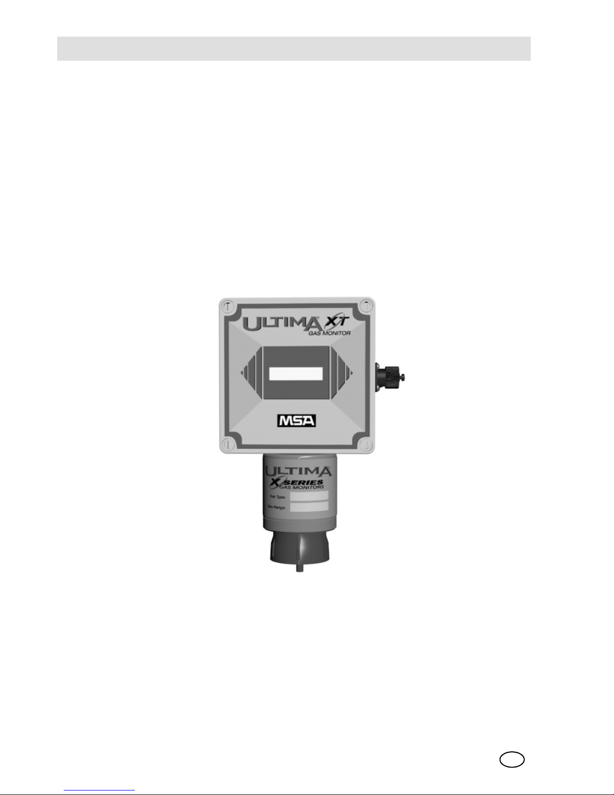
2.2 Identifying Your Unit
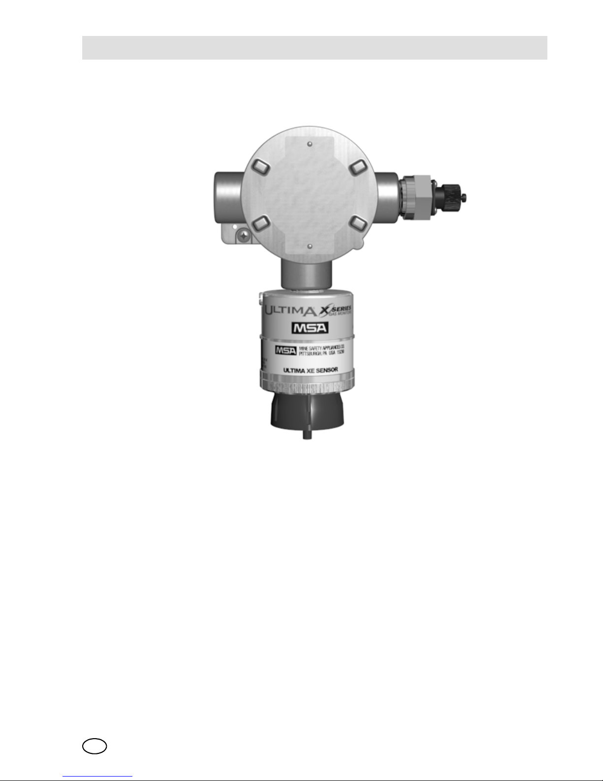
The ULTIMA XT Gas Monitor is housed in a rugged, plastic general-purpose enclosure [Æ Fig. 1].
Fig. 1 General-Purpose ULTIMA XT Monitor
The ULTIMA XL Gas Monitor is housed in a 316 stainless steel explosion-proof/
flameproof enclosure [Æ Fig. 2].
Page 15
IntroductionMSA
ULTIMA XL/ULTIMA XT
GB
15
Fig. 2 Flameproof ULTIMA XL Monitor
Page 16

MSAIntroduction
ULTIMA XL/ULTIMA XT
16
GB
The ULTIMA XIR Gas Monitor is housed in a 316 stainless steel flameproof enclosure [Æ Fig. 3].
Fig. 3 Flameproof ULTIMA XL with IR Monitor
Remote Sensor Models are shown in Æ Fig. 4, Æ Fig. 5 and Æ Fig. 6.
Page 17
IntroductionMSA
ULTIMA XL/ULTIMA XT
GB
17
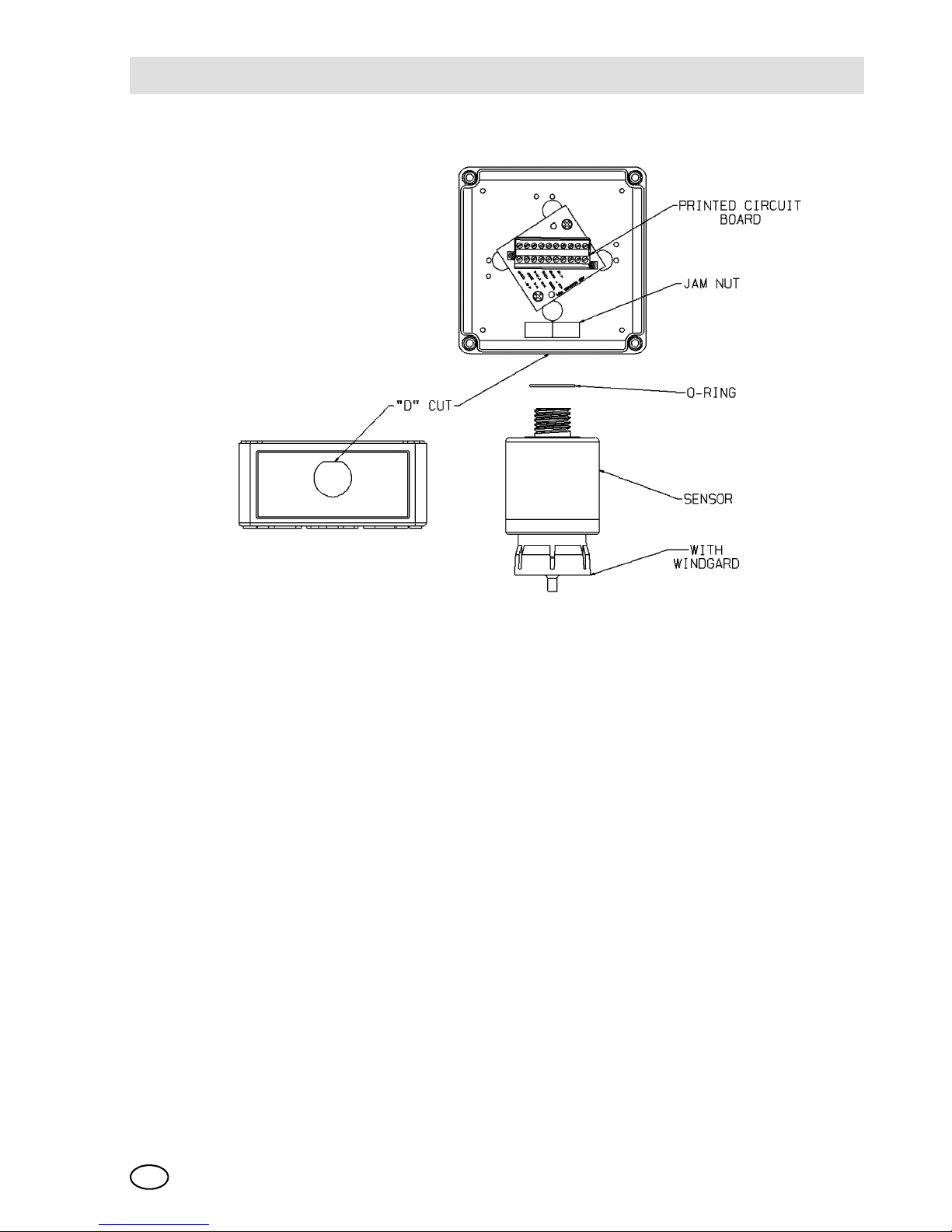
Fig. 4 General-Purpose XT Remote Sensor Model
Page 18
MSAIntroduction
ULTIMA XL/ULTIMA XT
18
GB
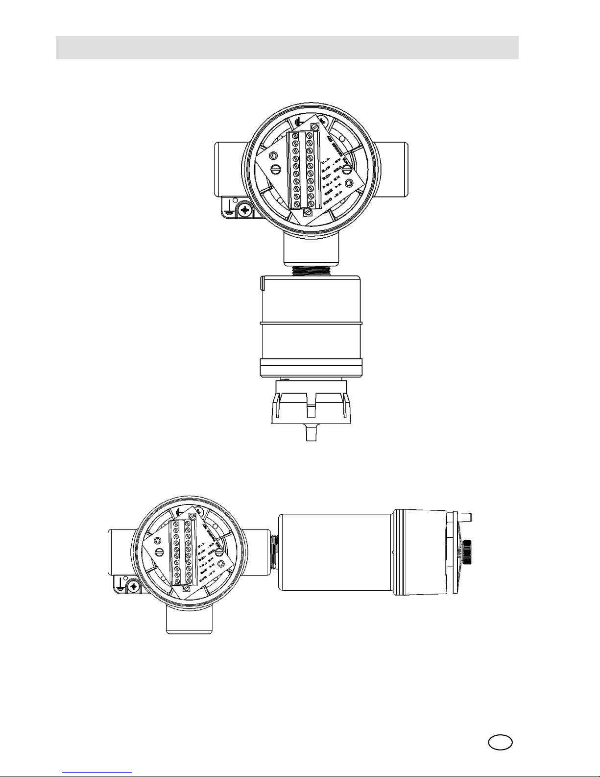
Fig. 5 Flameproof XL Remote Sensor Model
Fig. 6 Flameproof XIR Remote Sensor Model'
Page 19
IntroductionMSA
ULTIMA XL/ULTIMA XT
GB
19
To determine your sensor type and options, check the shipping carton. Checked
items are included in the carton. Also check the sensor ID label located on the sensor module. The carton label identifies:
- Type of unit supplied [Gas Monitor, Gas Monitor Less Sensor, or
Sensing Module]
- Type of gas [combustible gas, toxic gas or oxygen]
- Range [% LEL, PPM [parts per million], or %]
- Output [3 wire, 4 to 20 mA]
2.3 Installing Your Gas Monitor
Generally, the ULTIMA X Series Gas Monitors or remote sensing module should be
mounted close to the area where a leak is likely to occur or where the gas is expected. Install the ULTIMA X Series Gas Monitors or the remote sensing module at a
high level [ceiling] or low level [floor], depending on the density of the gas most likely
to be found.
For further information see installation drawings in the appendix.
Attention!
Mount the ULTIMA Gas Monitor or the remote sensor module with the
sensor inlet fitting [Æ Fig. 1, Æ Fig. 2, Æ Fig. 4 or Æ Fig. 5] pointed
downward; otherwise, the inlet may become clogged with particulate
matter or liquids.
Mount the ULTIMA XIR Gas Monitor or Remote Sensing Module with the
sensor inlet fitting extended horizontally from the main enclosure
Æ Fig. 3 and Æ Fig. 6] to help prevent the build-up of particulate or liquid
matter on the monitor's optical surfaces.
Do not paint the ULTIMA X Series Gas Monitors. If painting is done in an
area where a sensor is located, exercise CAUTION to ensure paint is not
deposited on the sensor inlet fitting. Such paint deposits would interfere
with the diffusion process, whereby a sample of the monitored atmosphere diffuses into the sensor. In addition, solvents in the paint may
cause an alarm condition to occur.
Protect the ULTIMA X Series Gas Monitors from extreme vibration. Do
not mount sensing head in direct sunlight as this may cause overheating
of the sensor.
Page 20
MSAIntroduction
ULTIMA XL/ULTIMA XT
20
GB
2.4 Installing the ULTIMA XT Gas Monitor
Remove lid and drill enclosure for power/signal cable entry. Use one of the following
methods to mount the general-purpose ULTIMA XT Gas Monitor/Less Sensor or
the ULTIMA XT Gas Monitor.
- Using customer-installed wiring holes, install the ULTIMA XT Gas Monitor to the
end of rigid conduit.
- Use mounting holes in the corners of the ULTIMA XT enclosure to mount directly to a wall.
Warning!
Do not locate the general-purpose enclosure models in an area which
may contain a flammable mixture of gas and air; otherwise, an explosion
may occur. The general-purpose ULTIMA X Series Gas Monitors can be
a source of ignition and must not be mounted in an area where a flammable mixture of combustible gas and air may become present; otherwise, an explosion may occur. If such a location must be monitored, use
a flameproof gas monitor.
Page 21
IntroductionMSA
ULTIMA XL/ULTIMA XT
GB
21
2.5 Installing the ULTIMA XL Gas Monitor
Fig. 7 Flameproof XIR Remote Sensor Model
- The ULTIMA XL Gas Monitor main enclosure can be rotated 360° and mounted
to ensure easy access to any of the three entryways. The electronics assembly
can be installed in any of the four self-aligning positions to allow proper sensor
orientation.
- The ULTIMA XL Gas Monitor sensor is not shipped attached to the main enclosure. Mount the sensor module with the applicable conduit only. Ensure the sensor wiring harness is through the entry and the sensor is pointing downward
[except IR, which mounts to the side]. Tighten with a strap wrench.
Page 22
MSAIntroduction
ULTIMA XL/ULTIMA XT
22
GB
2.6 Installing the ULTIMA XIR Gas Monitor
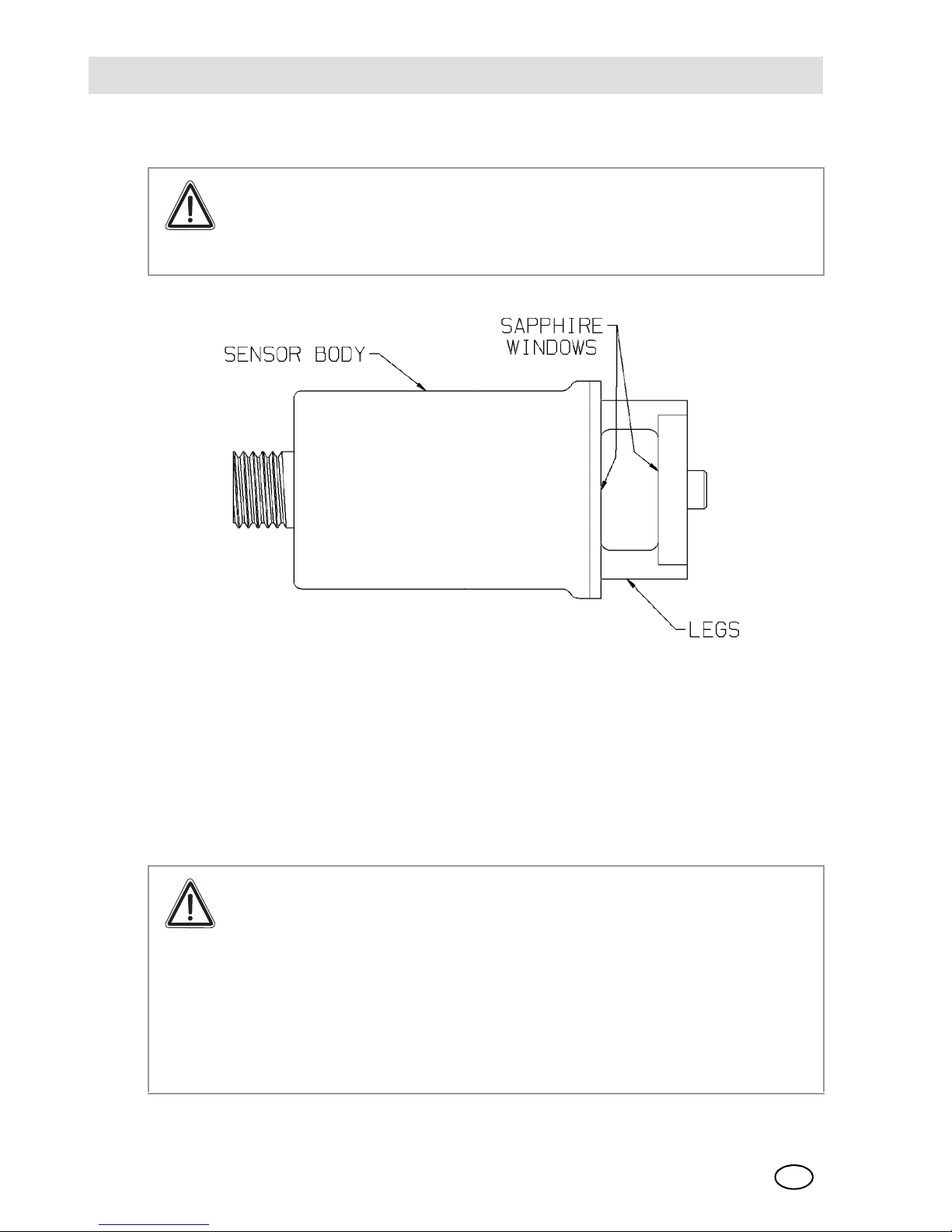
Fig. 8 ULTIMA XIR
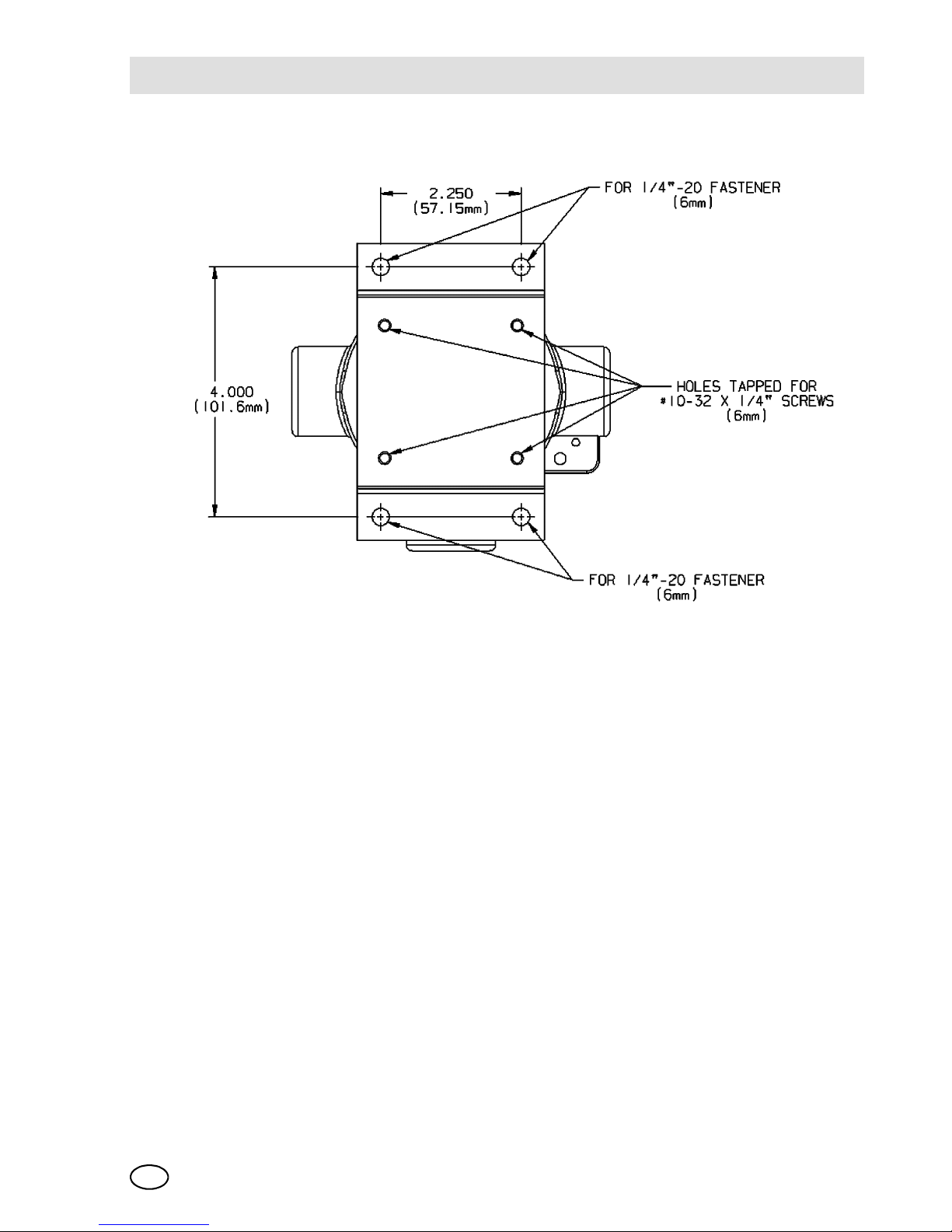
- Use the optional mounting strap [P/N 10047562] that can be attached to the rear
holes of the ULTIMA XL Gas Monitor [Æ Fig. 7].
- The ULTIMA XL Gas Monitor main enclosure can be rotated 360° and mounted
to ensure easy access to any of the three entryways. The electronics assembly
can be installed in any of the four self-aligning positions to ensure the sensor is
properly oriented.
Warning!
The ULTIMA XIR Combustible Gas Monitor contains no user- or fieldserviceable parts and must be returned to the factory for repair. Any attempt to open the monitor will damage the unit and void the warranty.
Attention!
Under no circumstances should a tool or excessive force be applied to
the two legs that support the unit's reflectors during installation or removal of the sensor [Æ Fig. 8]. Applying force to the legs can permanently
damage the monitor.
It is recommended that the monitor's environmental guard be installed
on the unit at all times. If the monitor is to be operated without the guard,
frequent checks should be made to ensure particulate or liquid matter
has not collected on the windows.
Page 23
IntroductionMSA
ULTIMA XL/ULTIMA XT
GB
23
2.7 Electrical Connections for ULTIMA X Gas Monitors
This assembly is marked to identify power, ground and signal connections.
A three-wire connection is required for all:
- Combustible Gas models
- Toxic and Oxygen Models with 4 to 20 mA output.
2.8 Wiring for all Models
Installation
General Information
Installation Instructions for Following the EMC Directives
The devices of MSA have been developed and tested in accordance with the EMC
Directives 89/336/EEC, 91/263/EEC, 92/31/EEC, and 93/68/EEC and the corresponding standards EN 50270. The requirements of the EMC Directives can only
be met by following the manufacturer’s installation instructions. This applies only to
tested devices and systems of the manufacturer.
General Instructions on the Installation of Tested Devices and Systems of
MSA to ensure that the EMC Directives are followed
- For the connection of the various devices to the power supply system a faultfree ground or fault-free equipotential bonding must be provided
- An appropriate supply voltage free of feedback to the external source in accordance with the EMC Directives must be used.
- If the devices are supplied from a direct voltage [DC] source, the supply cable
must be screened.
- Screened cable is to be used to connect the sensors.
Warning!
Before wiring the ULTIMA X Series Gas Monitors, disconnect power
source supplying the monitor; otherwise, electrical shock could occur.
For ULTIMA XL and XIR installations, the internal grounding terminal
must be used for equipment grounding. The external grounding terminal
is only to be used as a supplemental bonding connection where local authorities permit or require such a connection.
Page 24

MSAIntroduction
ULTIMA XL/ULTIMA XT
24
GB
- Control cables must be screened [reset, acknowledge, measurement current
output, printer, etc.].
- Screened cable must have at least 80 % coverage by the screening.
- Control and sensor cables must be laid physically apart from power supply cables.
- Screened cables must be laid in one piece. If it should prove necessary to extend a cable by way of a terminal box, the terminal box must be screened, and
the connections in the box must be kept as short as possible.
- Unscreened cables and cables from which the insulation has been stripped
must be as short as possible and must be laid without loops to the appropriate
terminal posts.
- External devices that are operated by the gas warning units [horns, contactors,
pumps, motors, etc.] must be radio-screened and follow the EMC Directives.
- If the EMC filters of the device are physically remote, the power supply cable
between the filter and the device must be screened.
- If additional high-voltage surge protection measures are required an appropriate high-voltage protection filter, approved by MSA, must be installed in the sensor cable.
Instructions on Meeting the EMC Requirements on the ULTIMA XL
To meet the EMC product standard EN 50270 [Electromagnetic Compatibility], the
following points must be observed:
General:
- A clean grounding point must be provided for the equipotential bonding.
- Power supply cables are to be kept away from remote measurement/data lines
[> 30 cm].
- All cables, unless otherwise specified, must be screened [> 80% coverage];
they are to be connected to the rack.
- The rack is to be equipped with separate equipotential bonding.
- The connection of the cable screen should be as short as possible.
- Cables for data transmission must be screened. There must not be any potential
difference between the interface of the cable screen and ground. The cable
screen must have good contact with the housings of the plug connectors.
For further information see installation drawings in the appendix.
Page 25
IntroductionMSA
ULTIMA XL/ULTIMA XT
GB
25
Conduit may also be needed in areas where large amounts of electrical noise is expected.
Use caution when selecting a cable size. The following tables express the maximum cable length when only using the ULTIMA X Series Gas Monitors.
ULTIMA X Series options may take additional power which requires a heavier cable
or a short cable run.
When selecting cable size, consider future needs [i.e., addition of sensors and/or
options available with the ULTIMA X Series Monitors]. See Chapter 4, "Specifications" for proper input voltage.
Ensure that water and dirt are not able to enter the unit via the wire or conduit. If the
unit is installed in a location known to be wet or damp, it is good practice to loop or
bend the entry into the unit that prevents water incursion.
Use of External Controllers
The ULTIMA X Series Gas Monitors may be connected to any device capable of
accepting 4 to 20 mA analog signals such as:
- Gasgard XL
- Model 9010/9020 Controller unit
- Suprema Controller
- Programmable controllers
- DCS's, etc.
An external power supply is required. [For power requirements, see Chapter 4,
"Specifications".] All connections should be made by following appropriate wire
code procedures.
- See following tables for typical cable length and wire size for installation.
Warning!
When using any of the ULTIMA X Series accessories with the 4 to 20 mA
output ULTIMA X Series Gas Monitor, a three-wire connection must be
used. Failure to use a three-wire connection could damage the electronics within the ULTIMA X Series Gas Monitor.
Be sure to install your ULTIMA X Series Gas Monitor according to National and local procedural codes. Failure to do so can result in an unsafe condition.
Page 26
MSAIntroduction
ULTIMA XL/ULTIMA XT
26
GB
ULTIMA XL and XT Maximum Cable Length and 4-20 mA Signal Load
2.9 ULTIMA XIR
Maximum Cable Length and 4-20 mA Signal Load
- The ULTIMA XL/XT Gas Monitors operate in the current source mode
[Æ Fig. 10 for general-purpose]
[Æ Fig. 11 for explosion-proof/flameproof].
Power Supply 24 Volts
Cable Size
1.00 mm2 Cable [18 AWG] 762 m [2500 ft]
1.50 mm
2
Cable [16 AWG] 1280 m [4200 ft]
2.50 mm
2
Cable [12 AWG] 3048 m [10000 ft]
Max. Load on 4-20 mA Signal 500 Ohms
Power Supply 24 Volts
CONFIGURATION
1.00 mm
2
Cable [18 AWG] 610 m [2000 ft]
1.50 mm2 Cable [16 AWG] 1070 m [3500 ft]
2.50 mm
2
Cable [12 AWG] 1524 m [5000 ft]
Max. Load on 4-20 mA Signal 500 Ohms
The HART communications require the load on the 4-20 mA to be
between 230 to 500 ohms.
Page 27
IntroductionMSA
ULTIMA XL/ULTIMA XT
GB
27
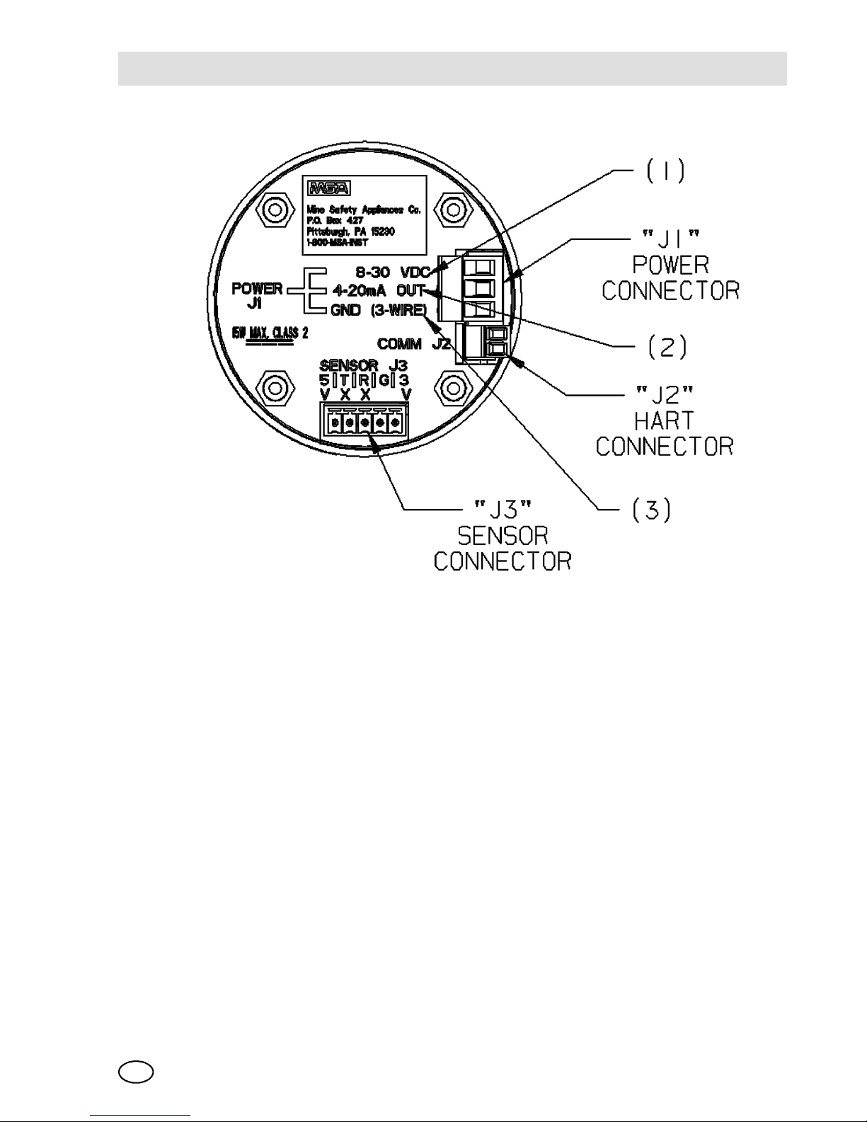
Fig. 9 Circuit Board
(1) Connect 24 VDC power lead to J1-1 [Æ Fig. 9].
(2) Connect J1-2 to 4 to 20 mA input on remote system.
(3) Connect the signal ground to J1-3.
(4) Connect the sensor module to labeled connector J-3 on the main pc board.
(5) Assemble lid on enclosure.
Page 28

MSAIntroduction
ULTIMA XL/ULTIMA XT
28
GB
Fig. 10 General-Purpose Three-Wire 4-20 mA Operation
Fig. 11 Flameproof Three-Wire 4-20 mA Operation
Page 29
IntroductionMSA
ULTIMA XL/ULTIMA XT
GB
29
2.10 Installing the ULTIMA X Remote Sensor Module
The Remote Sensor Module is used with the ULTIMA X Gas Monitor/less sensor.
The Remote Sensor Module can be mounted in a manner similar to the gas monitor
installation in the preceding procedure and at a maximum distance outlined in
“Remote Module Wiring and Placement“.
Permanently connect 6 mm [1/4"] ID tubing to the post on the environmental guard.
Route this tubing to the ULTIMA X Gas Monitor, ensuring that there are no kinks,
leaks or other obstructions. Secure this tubing near the monitor; it is used to deliver
check gas to the sensor module during calibration.
2.11 Electrical Connections for the ULTIMA X Series Remote
Sensor Module
Five conductors are required for the ULTIMA XL and ULTIMA XT Remote Sensor
Modules to operate catalytic or electrochemical sensor modules of the ULTIMA XE
type. Four conductors are required for the ULTIMA XIR Remote Sensor Module.
The ULTIMA X Series Monitor has a five-wire terminal to accommodate up to
1.50 mm
2
[16 AWG] conductors.
For open wiring, shielded wire or cable should be used to minimize the possibility
of noise interference and contact with other voltages. Selection of this shielded cable must comply with local requirements.
Warning!
Before wiring the ULTIMA X Series Remote Sensor Module, disconnect
the power source feeding the Remote Sensor Module and the ULTIMA X
Series Gas Monitor/Less Sensor; otherwise, electrical shock could occur.
Attention!
When installing an ULTIMA X Series Remote Sensor Module with its
mating ULTIMA X Series Gas Monitor/Less Sensor, follow National
Electrical and local procedural Codes for US, or relevant codes for country of installation; failure to do so can result in an unsafe condition.
Page 30
MSAIntroduction
ULTIMA XL/ULTIMA XT
30
GB
Remote Module Wiring and Placement
At the ULTIMA X Series Remote Sensor Location:
(1) Open the ULTIMA X Series Remote Sensor cover by removing lid.
For the ULTIMA XT Gas Monitor, route the cable from the Gas Monitor
through a customer-supplied opening in the enclosure and wire it to the terminal block [Æ Fig. 4].
For the ULTIMA XL or XLIR Gas Monitor, route the cable from the Gas Mon-
itor through a wire entry hole in the enclosure and wire it to the terminal block
[Æ Fig. 5 or Æ Fig. 6].
(2) Verify the identity of each conductor of the cable and connect the wire to the
terminal block.
(3) Re-install the cover of the ULTIMA X Series Remote Sensor.
Gas Type Minimum Wire Size Maximum Distance
Toxic, Oxygen and
Catalytic Combustible
1.00 mm
2
[18 AWG] 15.2 m [50 ft]
1.50 mm2 [16 AWG] 30.5 m [100 ft]
*IR Combustible 1.50 mm
2
[16 AWG] 15.2 m [50 ft]
2.50 mm2 [12 AWG] 30.5 m [100 ft]
CE-Approved instruments have a maximum 15 m [50 ft.]
distance.
Incoming power and signal cable shield should be earth grounded at the
power source. Connect power and remote sensor cable shields together
in the main housing.
Page 31

Start-up and CalibrationMSA
ULTIMA XL/ULTIMA XT
GB
31
3 Start-up and Calibration
3.1 Initial Start-up
- The ULTIMA X Series Gas Monitors are factory-calibrated and ready for imme-
diate use.
- During the 30-second warm-up, the output signal is the same as the calibration
signal when enabled during a normal calibration. This is described later in this
chapter under "ULTIMA X Series Gas Monitor Calibration Output Signal".
- For units with LEDs, the Alert red LED is solid ON during the 30-second warm-
up.
- The Normal green LED is solid ON after the 30-second warm-up.
- A complete listing of instrument operation features can be found in
“Instrument Operation“.
During normal operation, the ULTIMA X Monitor outputs the gas concentration of
the surrounding environment through a digital HART connection on the 4-20 mA
line or local HART controller. The corresponding 4-20 mA output signal can be
transmitted to a controller or DCS [distributed control system]. Setup and calibration
can be performed through this connection. HART communication requires the 420 mA line be terminated with 230 - 500 ohms of resistance.
The catalytic combustible model of the ULTIMA X Series Gas Monitors
is capable of detecting concentrations of certain combustible gases
above 100% LEL. When exposed to these concentrations, the ULTIMA
X Series Gas Monitors will display one of two modes:
+LOC % LEL - The ULTIMA X Series Gas Monitor has been exposed to
a high concentration of gas [above the LEL] and there is a possibility
that the over-range condition may still exist.
OVER % LEL - The ULTIMA X Series Gas Monitor has been exposed
to a high concentration of gas [above the LEL] and the over-range condition definitely still exists. The 4-20 mA output will be set to the LOC/
overrange value [21 mA] and the LOC and overrange flags will be set
on the HART monitor.
Page 32

MSAStart-up and Calibration
ULTIMA XL/ULTIMA XT
32
GB
In the +LOC % LEL mode, the output signal will also be locked at full-scale. If this
condition occurs, the ULTIMA X Series Gas Monitor must be unlocked by performing a "Zero Function" with the ULTIMA X Series HART Calibrator or Controller, or
by using the pushbutton interface. The ULTIMA X Series Gas Monitor will not revert
to a normal condition until a successful zero operation has been performed. This is
an exclusive safety feature of the ULTIMA X Series Gas Monitor which pre-empts
the possibility of ambiguous readings when the sensor is exposed to concentration
of gas above 100% LEL.
In the OVER % LEL mode, the combustible gas is over the 100% LEL range. It returns to normal operation when gas concentration level falls below 100% LEL.
Instrument Operation
Warning!
In either mode, correct the condition causing the excessive gas level and
vent or purge the area before attempting the following.
Operation
Green
LED
Red LED 4-20 mA Output
Normal No
Alarms
ON
steady
OFF Gas value
Alarming OFF Flashing Gas value
Fault OFF ON
steady
3.0 mA
Power Up/
Countdown
OFF ON
steady
ALERT option
1
disabled: 21.0 mA for
oxygen; 3.75 mA for others
ALERT option
1
enabled:3.75 mA for all
Sensor Missing/
Countdown
OFF ON
steady
3.0 mA if SWAP delay timeout
2
ex-
pired,
SWAP delay3 disabled or FAULT
Previous gas value if SWAP delay3 en-
abled and SWAP delay timeout2 not
expired
Sensor CAL
Apply Zero Gas
Flashing OFF 3.75 mA if cal signal enabled and
ALERT option1 enabled; gas value signal disabled
21.0 mA for oxygen if cal signal enabled and ALERT option
1
disabled
Page 33
Start-up and CalibrationMSA
ULTIMA XL/ULTIMA XT
GB
33
3.2 Calibration Basics
While the ULTIMA X Series Gas Monitor is factory-calibrated, it is good practice to
calibrate the unit once it is installed in its final environmental destination.
As with any type of gas monitor, the only true check of its performance is to a known
gas concentration to the sensor using a calibration adaptor. The frequency of the
calibration gas tests depends on the operating time and chemical exposures of the
sensors. New sensors should be calibrated more often until the calibration records
prove sensor stability. The calibration frequency can then be reduced to the schedule set by the safety officer or plant manager.
Before calibrating, the ULTIMA X Series Gas Monitor should be powered for a minimum of one hour to allow the sensor to settle into its new environment. ETO sensor
requires 24-hour warm-up time.
Sensor CAL
Apply Span Gas
Flashing ON 3.75 mA if cal signal enabled and
ALERT option
1
enabled; gas value sig-
nal disabled
21.0 mA for oxygen if cal signal enabled and ALERT option
1
disabled
CAL 4-20 OFF ON
steady
4 mA if 4 mA calibration selected
20 mA if 20 mA calibration selected
CAL Fault OFF ON
steady
Gas value
Underrange OFF ON
steady
3.0 mA if gas value 0 or less; gas value
otherwise
Overrange/LOC ON
steady
OFF
4
21.0 mA
1
See Chapter 3 for Alert option.
2
Swap Delay timeout is 60 seconds if enabled; 0 seconds otherwise.
3
See Chapter 3, "Command #180: Write Sensor Swap Delay Enable" for SWAP
Delay option.
4
Alarming operation is followed if the alarms are enabled.
Operation
Green
LED
Red LED 4-20 mA Output
Attention!
Before attempting a calibration, power the unit at least one full hour.
Page 34
MSAStart-up and Calibration
ULTIMA XL/ULTIMA XT
34
GB
Non-combustible Chemicals that Reduce Catalytic Sensor Sensitivity
Catalytic Combustible sensors located in areas where non-combustible chemicals
may leak, particularly ones known to reduce the sensitivity [see following list] should
be calibrated after such exposures.
- Silanes, Silicates, Silicones, Lead, Hydrogen Sulphide, organic Phosphates
and Halides [compounds containing Fluorine, Chlorine, Iodine or Bromine]
- “Sensor Response to Interferants“ in Chapter 4 lists interferants for electrochemical sensors.
When it is determined that calibration adjustments are required, the ULTIMA X Series Gas Monitor provides a one-man, non-intrusive method of adjustment at the
unit.
To calibrate the unit, one of the following accessories is necessary:
-HART
®
-compatible communications interface with Device Description Language capability [DDL] or generic HART interface with Manufacturer Specific
Command capability. See Chapter 4 for command definitions.
- Optional Push-button Calibration.
ULTIMA X Series Gas Monitor Calibration Output Signal
The ULTIMA X Series Gas Monitor is shipped with the calibration output signal disabled so the output signal will track the gas concentration value during the calibration process. In some applications, it may be desirable to disable or lock the output
to a pre-determined output value to prevent activation of alarm devices. The calibration signal can be enabled using a HART Controller with DDL or Manufacturer
Specific Command capability. When the calibration signal is enabled, the output
signal is 3.75 milliamps for the 4 to 20 milliamp output models during the calibration
cycle and for one minute after calibration is complete.
Attention!
To ensure a fully functional sensor, perform a calibration check and adjustments at initial start-up and at regular intervals.
For the range of 25% oxygen, the calibration signal will be 21 mA. Oxygen can be set to a 3.75 mA calibration signal by turning ON the ALERT
option.
Page 35

Start-up and CalibrationMSA
ULTIMA XL/ULTIMA XT
GB
35
3.3 ULTIMA X Series Gas Monitor Calibration Procedure
Read all calibration instructions before attempting an actual calibration. Also, identify and become familiar with all of the calibration components. During the calibration, it is necessary to quickly apply the span gas to the unit. Prior connection of the
calibration components will aid in the ease of unit calibration.
The only true check of any gas monitor's performance is to apply a known gas concentration to the sensor using a calibration adaptor. The calibration procedure must
be performed regularly.
INITIAL Calibration
When the unit is powered up for the first time, or when a new sensor module is
placed in the unit, an INITIAL Calibration is recommended. This procedure enables
the unit to gather data about the sensor to make accurate decisions for the
CHANGE SENSOR function and the CAL FAULT function to work properly. During
normal use, INITIAL calibration should only be used when a standard calibration will
not clear a fault condition due to use of incorrect calibration gas or another similar
situation.
Overview
The following report outlines the calibration procedure for the ULTIMA XL/XT Gas
Monitoring instrument using a Device Description Language capable HART communicator. The procedure is a menu-driven process using a series of user prompts
to indicate when to apply gas.
There are four HART calibration procedures available using the manufacturer specific commands and one sensor zero command available using a common practice
command. These are device automated procedures with screen prompts to indicate
when user interaction is needed to proceed. The steps and prompt screens are provided for each of the calibration procedures.
Each display screen gives the user the option of aborting the current calibration procedure at any time during the procedure. If aborted, the sensor retains the last calibration data recorded prior to the current procedure attempt.
The screen views show a windows directory tree menu structure. Other window
style menu presentations may be available on certain host machines but the calibration information screens should remain the same.
Additionally, some screens may not appear for all sensor types. The Oxygen sensor, for instance, does not show the 30-second zero countdown screen because
that sensor uses an electronic zero.
Page 36

MSAStart-up and Calibration
ULTIMA XL/ULTIMA XT
36
GB
See “Factory-set Span Values“ for the appropriate zero and span gas cylinders for
your ULTIMA/ULTIMA X Series Gas Monitor.
“Factory-set Span Values“ shows the recommended calibration gas concentration
and ULTIMA X Series Gas Monitors.
3.4 Span Gas Values
The ULTIMA X Monitor is factory-shipped with a preset span gas value. This span
gas value can be changed via the HART Controller; otherwise, the span gas must
correspond to preset concentrations. See Section 4 to change the span gas value.
The span gas value of ULTIMA X Gas Monitor catalytic combustible models are
pre-set to one of the broad categories shown in "Factory-set Span Values“. Specific
span gas values for all combustible models are listed under each category given in
"Calibration Guide for Combustible Gas Sensor“.
ULTIMA XL, flammable gas sensor - ATEX performance approval
The terms “trim” and “calibration” are used interchangeably within the
HART protocol. To promote interoperability for users accustomed to either term, both are used in the menu structure.
The calibration procedure for the sample draw ULTIMA XL/XT Monitor
is the same as the procedure for the diffusion version, except calibration
gas is applied to the calibration entry port of the inlet flow block and the
cal kit for pumped units provides a flow matching regulator.
Warning!
Calibration kits contain zero caps to use in place of zero calibration gas.
These caps can only be used when the ambient air does not contain the
gas the monitor is detecting. If there is any doubt, use zero gas when zeroing the ULTIMA X Monitor; otherwise, improper calibration could occur.
Warning!
Always calibrate for the least sensitive gas or vapor expected to be
measured; otherwise, instrument readings may be incorrect.
When monitoring flammable gas in safety related applications the
ULTIMA XE must be calibrated with a known concentration of the gas
being monitored.
Page 37

Start-up and CalibrationMSA
ULTIMA XL/ULTIMA XT
GB
37
The lower explosive limits [LEL] of the gases and vapours in following table were
taken from EN 61779. For gases and vapours not listed in EN 61779, the lower explosive limits [LEL] were taken from the Chemsafe [Dechema, Frankfurt] data base.
Local regulations may specify different LEL values; always ensure the correct values are used.
It is recommended that the ULTIMA XE zero is calibrated using clean air, free of
flammable gas, and calibration gas of approximately 50 % LEL in air of the gas being monitored. The table shows the ULTIMA XE flammable gas sensor relative response to various gases and vapours when calibrated using 50 % LEL Propane in
air. For non-safety related applications the ULTIMA XE flammable gas sensor may
be calibrated using the relative response factors shown in the table and 50 % LEL
Propane in air. When using relative response factors for gas calibration, deviations
of up to ±20 % of the true gas concentration can be expected
Reference calibration example for 50 % Methanol:
(1) Relative response factor for Methanol from the ta-
ble in this section
= 0.79
(2) Propane calibration gas concentration being used = 0.89 Vol% C
3H8
(3) Propane volume concentration for 100 % LEL = 1.7 Vol%
(4) Propane calibration gas concentration in % LEL
% LEL = 0.89 Vol% C3H8 x
100 % LEL
= 52.4 % LEL
1.7 Vol% C
3H8
(5) Gas calibration set point = 52.4 % LEL x 0.79 = 41.4 % LEL
Page 38

MSAStart-up and Calibration
ULTIMA XL/ULTIMA XT
38
GB
ULTIMA XE - Relative response factors
Relative response factors of tested gases for 0.89 vol% Propane calibration gas.
Measuring gas
100 % LEL-
in Vol%
Relative
response
factor
Response
time [t
50
]
*)
Response
time [t90]
*)
Acetone 2.5 Vol% 0.94 ≤ 19 s ≤ 49 s
Acetylene 2.3 Vol% 0.73 ≤ 12 s ≤ 25 s
Allyl alcohol [50 °C] 2.5 Vol% 0.81 ≤ 14 s ≤ 52 s
[FAM-] Benzine 65/95 1.1 Vol% 1.28 ≤ 12 s ≤ 33 s
1,3-Butadiene 1.4 Vol% 0.96 ≤ 16 s ≤ 34 s
i-Butane 1.5 Vol% 1.07 ≤ 17 s ≤ 36 s
n-Butane 1.4 Vol% 1.13 ≤ 16 s ≤ 38 s
2-Butanon 1.8 Vol% 1.19 ≤ 12 s ≤ 46 s
i-Butylene 1.6 Vol% 0.92 ≤ 16 s ≤ 37 s
Cyclohexane 1.2 Vol% 1.25 ≤ 13 s ≤ 30 s
Cyclopentane 1.4 Vol% 1.15 ≤ 19 s ≤ 47 s
Diethyl Ether 1.7 Vol% 1.13 ≤ 18 s ≤ 41 s
Ethane 2.5 Vol% 0.79 ≤ 14 s ≤ 30 s
Ethanol 3.1 Vol% 0.90 ≤ 10 s ≤ 27 s
Ethylene 2.3 Vol% 0.77 ≤ 13 s ≤ 27 s
Ethyl Acetate 2.2 Vol% 1.07 ≤ 19 s ≤ 59 s
Ethylene Oxide 2.6 Vol% 0.94 ≤ 15 s ≤ 37 s
n-Hexane 1.0 Vol% 1.48 ≤ 12 s ≤ 28 s
Methanol 5.5 Vol% 0.79 ≤ 16 s ≤ 41 s
n-Pentane 1.4 Vol% 1.13 ≤ 19 s ≤ 46 s
Propane 1.7 Vol% 1.00
≤ 11 s ≤ 26 s
2-Propanol 2.0 Vol% 1.07 ≤ 11 s ≤ 34 s
Propene 2.0 Vol% 0.76 ≤ 14 s ≤ 30 s
Propylene Oxide 1.9 Vol% 1.03 ≤ 18 s ≤ 43 s
Hydrogen 4.0 Vol% 0.56 ≤ 8 s ≤ 15 s
*) ULTIMA XE response times with flow block and a flow rate of 1 l/min.
Page 39

Start-up and CalibrationMSA
ULTIMA XL/ULTIMA XT
GB
39
ULTIMA XL, with infrared gas sensor - ATEX performance approval
The lower explosive limits [LEL] of the gases and vapours in the following tables
were taken from EN 61779. For gases and vapours not listed in EN 61779, the lower explosive limits [LEL] were taken from the Chemsafe [Dechema, Frankfurt] data
base. Local regulations may specify different LEL values; always ensure the correct
values are used.
It is recommended that the ULTIMA XIR zero is calibrated using clean air, free of
flammable gas, and calibration gas of approximately 50 % LEL in air of the gas being monitored. If it is not possible to calibrate with the same gas as the measuring
gas then the Propane [C
3H8
] reference gas concentration together with the relative
response factors shown in the table can be used. The table shows the ULTIMA XIR
flammable gas sensor relative response to various gases and vapours when calibrated using 50 % LEL Propane in air. For non-safety related applications the
ULTIMA XIR flammable gas sensor may be calibrated using the relative response
factors shown in the 'ULTIMA XIR Relative response factors' table and 50 % LEL
Propane in air. When using relative response factors for gas calibration, deviations
of up to ±20 % of the true measuring gas concentration can be expected.
These relative response factors only apply at ambient temperatures of 20 °C and
unless otherwise indicated.
When monitoring flammable gas in safety related applications the
ULTIMA XL must be calibrated with a known concentration of the gas
being monitored.
Page 40

MSAStart-up and Calibration
ULTIMA XL/ULTIMA XT
40
GB
Reference calibration example for Methanol when using propane:
ULTIMA XIR - Relative response factors for Propane calibration Gas
(1) Relative response factor for Methanol from the
table in this section
= 0.70
(2) Propane calibration gas concentration being used = 0.89 Vol% C
3H8
(3) Propane volume concentration for 100 % LEL = 1.7 Vol%
(4) Propane calibration gas concentration in % LEL
% LEL = 0.89 Vol% C
3H8
x
100 % LEL
= 52.4 % LEL
1.7 Vol% C3H
8
(5) Gas calibration set point = 52.4 % LEL x 0.79 = 36.7 % LEL
Measuring gas
100 % LEL in
Vol%
Linearisation
curve
Reference Gas
Concentration
[Propane]
Relative
response
factor
Acetone 2.5 Vol% (8) Ethylene 0.25 Vol% 3.31
Allyl alcohol
[50 °C]
2.5 Vol% (2) Propane 0.25 Vol% 3.31
[FAM-] Benzine
65/95
1.1 Vol% (2) Propane 0.89 Vol% 1.10
1,3-Butadiene 1.4 Vol% (8) Ethylene 0.25 Vol% 5.97
i-Butane 1.5 Vol% (4) Butane 0.89 Vol% 1.08
n-Butane 1.4 Vol% (4) Butane 0.89 Vol% 1.08
2-Butanon 1.8 Vol% (2) Propane 0.41 Vol% 2.06
i-Butyl Acetate 1.3 Vol% (2) Propane 0.89 Vol% 1.46
n-Butyl Acetate
[50 °C]
1.3 Vol% (2) Propane 0.89 Vol% 1.41
i-Butylene 1.6 Vol% (6) Hexane 0.41 Vol% 1.95
Cyclopentane 1.4 Vol% (7) Cyclo-
pentane
0.89 Vol% 0.94
Diethyl Ether 1.7 Vol% (2) Propane 0.89 Vol% 1.22
Ethane 2.5 Vol% (3) Ethane 0.89 Vol% 0.90
Ethanol 3.1 Vol% (6) Hexane 0.89 Vol% 1.06
Ethyl Acetate 2.2 Vol% (2) Propane 0.61 Vol% 1.52
Ethylene Oxide 2.6 Vol% (6) Hexane 0.41 Vol% 1.91
Page 41

Start-up and CalibrationMSA
ULTIMA XL/ULTIMA XT
GB
41
ULTIMA XIR - Relative response to 50 % LEL
The ULTIMA XIR response to 50 % LEL of the measuring gas, when configured to
linearisation curve number 2 [Propane] and calibrated in clean air and 50 % LEL
Propane, is shown in below for various flammable gases and vapours.
When using relative response factors for gas calibration, deviations of up to ±20 %
of the true measuring gas concentration can be expected.
n-Hexane 1.0 Vol% (6) Hexane 0.89 Vol% 1.27
Methanol 5.5 Vol% (3) Ethane 0.89 Vol% 0.70
n-Nonane 0.7 Vol% (2) Propane 0.89 Vol% 1.37
n-Pentane 1.4 Vol% (2) Propane 0.89 Vol% 0.99
Propane 1.7 Vol% (2) Propane 0.85 Vol% 1.00
2-Propanol 2.0 Vol% (6) Hexane 0.61 Vol% 1.30
Propylene 2.0 Vol% (2) Propane 0.41 Vol% 2.32
Propylene Oxide
1.9 Vol% (2) Propane 0.61 Vol% 1.44
Toluene 1.1 Vol% (8) Ethylene 0.25 Vol% 3.75
Xylene 0.96 Vol% (2) Propane 0.41 Vol% 2.56
Response time with measuring gas when using the ULTIMA XIR Flow Cap
[flow rate 1 l/min.]: 50 = 10 s, t
90
= 30 s.
Measuring gas
100 % LEL in
Vol%
Response to 50 % LEL of the
measuring gas
Acetone 2.5 Vol% 15 % LEL
Acetylene 2.3 Vol% 0 % LEL
Allyl alcohol [50 °C] 2.5 Vol% 16 % LEL
Ammonia 15 Vol% 0 % LEL
[FAM-] Benzine 65/95 1.1 Vol% 46 % LEL
1,3-Butadiene 1.4 Vol% 7 % LEL
i-Butane 1.5 Vol% 49 % LEL
n-Butane 1.4 Vol% 47 % LEL
2-Butanon [MEK] 1.8 Vol% 25 % LEL
i-Butyl Acetate 1.3 Vol% 34 % LEL
Measuring gas
100 % LEL in
Vol%
Linearisation
curve
Reference Gas
Concentration
[Propane]
Relative
response
factor
Page 42

MSAStart-up and Calibration
ULTIMA XL/ULTIMA XT
42
GB
n-Butyl Acetate 1.3 Vol% 36 % LEL
i-Butylene 1.6 Vol% 25 % LEL
Cyclohexane 1.2 Vol% 31 % LEL
Cyclopentane 1.4 Vol% 53 % LEL
Diethyl Ether 1.7 Vol% 42 % LEL
Acetic Acid [50 °C] 4.0 Vol% 78 % LEL
Acetic Anhydride [50°C] 2.0 Vol% 2 % LEL
Ethane 2.5 Vol% 56 % LEL
Ethanol 3.1 Vol% 48 % LEL
Ethylene 2.3 Vol% 8 % LEL
Ethyl Acetate 2.2 Vol% 33 % LEL
Ethylene Oxide 2.6 Vol% 27 % LEL
n-Hexane 1.0 Vol% 40 % LEL
Methanol 5.5 Vol% 73 % LEL
n-Nonane 0.7 Vol% 37 % LEL
n-Pentane 1.4 Vol% 51 % LEL
Propane 1.7 Vol% 50 % LEL
2-Propanol 2.0 Vol% 40 % LEL
Propylene 2.0 Vol% 22 % LEL
Propylene Oxide 1.9 Vol% 35 % LEL
Toluene 1.1 Vol% 15 % LEL
Hydrogen 4.0 Vol% 15 % LEL
Xylene 0.96 Vol% 20 % LEL
Measuring gas
100 % LEL in
Vol%
Response to 50 % LEL of the
measuring gas
Page 43

Start-up and CalibrationMSA
ULTIMA XL/ULTIMA XT
GB
43
Factory-set Span Values
Gas Type Range
SPAN Gas Preset
Values
Carbon Monoxide 0-100 ppm;
0-500 ppm
60 ppm
300 ppm
Sulfur Dioxide 0-25 ppm 10 ppm
Hydrogen Sulfide 0-25 ppm
0-10 ppm
0-50 ppm
5 ppm
40 ppm
40 ppm
Nitric Oxide 0-100 ppm 50 ppm
Nitrogen Dioxide 0-10 ppm 5 ppm
Chlorine 0-5 ppm 2 ppm
Hydrogen Cyanide 0-50 ppm 10 ppm
Chlorine Dioxide 0-3 ppm 1 ppm
Oxygen 0-10%; 0-25% 5%; 20.8%
Natural Gas 0-100% LEL 25% LEL
Petroleum Vapors [Gasoline] 0-100% LEL 40% LEL
General Solvents 0-100% LEL 55% LEL
Non-Methane IR 0-100% 29% LEL
Methane IR 0-100% LEL 50% LEL
Phosphine 2.0 ppm 0.5 ppm
Arsine 2.0 ppm 1.0 ppm
Germane 3.0 ppm 2.5 ppm
Silane 25 ppm 5 ppm
Diborane 50 ppm 15 ppm
Fluorine 5.0 ppm 4.0 ppm
Bromine 5.0 ppm 2.5 ppm
Ammonia 0-50 ppm 25 ppm
Hydrogen 0-1000 ppm 500 ppm
ETO 0-10 ppm 4.0 ppm
Hydrogen Chloride 0-50 ppm 40 ppm
Page 44

MSAStart-up and Calibration
ULTIMA XL/ULTIMA XT
44
GB
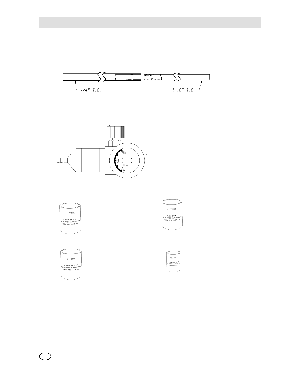
Fig. 12 Calibration Kit 40 Contents [Your Kit may also include one or two gas cylinders]
Item 1 - Tubing [P/N 711112]
• 3/16" ID side connects to Item 3
• 1/4" ID side connects to sensor
Item 2 - Zero Cap [P/N 710535]
Item 3 - 1.5 LPM flow Controller [P/N 478358]
Page 45
Start-up and CalibrationMSA
ULTIMA XL/ULTIMA XT
GB
45
If you wish to calibrate to the specific LEL of the gas or vapor being measured, the
expected span gas value of the ULTIMA/ULTIMA X Series Gas Monitor can be
changed by the HART Controller.
Fig. 13 Calibration Kit 41 Contents [Your Kit may also include one or two gas cylinders]
Item 1 - Tubing [P/N 711112]
• 3/16" ID side connects to Item 3
• 1/4" ID side connects to sensor
Item 3 - 1.5 LPM flow Controller
[P/N 478358]
Item 3 - Calibration Cap[P/N 710411] Item 4- Zero Cap [P/N 813774]
Item 5 - Calibration Cap [P/N 10020030] Item 6 - Zero Cap [P/N 710535]
Page 46

MSAStart-up and Calibration
ULTIMA XL/ULTIMA XT
46
GB
3.5 ULTIMA X Series Gas Monitor Calibration
In some cases, it may be necessary to perform only a zero function of the
Gas Monitor in lieu of a full zero and span procedure. Check with your safety officer
or safety engineer to determine if only a zero function is necessary.
Calibration of Hydrogen Chloride Gas Monitors must be performed as follows:
[Does only apply for non ex-approved ULTIMA XT version.]
(1) Use MSA Hydrogen Chloride [HCl] cylinder [P/N 10028078], 40 ppm Hydro-
gen Chloride.
(2) Start with a NEW 1.5 LPM flow control regulator [P/N 478358] and tubing
[P/N 711112] dedicated only for use with Hydrogen Chloride gas and included
in Cal Kit #54.
(3) Before starting a calibration, run HCl gas through the flow control regulator and
tubing for a minimum of five minutes.
(4) Perform calibration per the Instructions that follow.
(5) After a successful calibration, flush the flow control regulator and tubing with
100% Nitrogen for five minutes.
(6) Store the flow control regulator in a desiccated, sealed bag or container to
maintain regulator performance.
- Calibration Kit #54 contains the parts listed above for a Hydrogen Chloride diffusion calibration.
Warning!
To ensure a fully functional sensor, perform calibration checks and adjustments at initial start-up and at regular intervals.
If this is the first calibration or, if the sensor element has been changed
or replaced, see Section 2, "Initial Calibration."
If this is an oxygen sensor, see Section 2, "Oxygen Calibration."
If this is an XIR sensor, see Section 2, "XIR Calibration."
Apply power to the unit at least 1 hour before calibrating. ETO sensor
requires 24-hour warm-up time.
If regulator is properly flushed and stored in a sealed bag with desiccant
provided in Cal Kit #54 or equivalent dry container, start with step 3 for
future calibrations.
Page 47
Start-up and CalibrationMSA
ULTIMA XL/ULTIMA XT
GB
47
3.6 Standard Calibration
A standard calibration includes a "zero" and "span" procedure as described in the
following procedures. If the user chooses to only perform a "zero" procedure, they
may do so by selecting the ZERO function on the HART communicator instead of
the CALIBRATE selection as described as follows, or by using the optional pushbutton calibration as outlined in Chapter 2, "Optional Push-button Calibration".
Zeroing
(1) If Using the zero cap:
If the ambient air is suitable, with no traces of the gas of interest, place the
appropriate Calibration Kit zero cap over the Environmental guard inlet and
wait two minutes; otherwise, use zero gas.
(2) If Using zero gas cylinder:
Locate the zero gas cylinder and the Calibration Kit Flow Controller.
Screw the Flow Controller onto the top of the zero gas cylinder.
Locate the Tube Assembly from the cal kit.
Push the smaller end of the tube Assembly over the Flow Controller Gas
Outlet and ensure tubing completely covers the gas outlet.
Turn on the zero gas flow by turning the knob on the flow controller.
(3) Connect the HART communicator to the ULTIMA XL/XT instrument or across
the 4-20 mA line and select ZERO function from the menu or select the zero
or calibration function as described in the following procedures.
Z The green LED should be flashing.
Z The red LED should be OFF.
The zero or calibration process can be aborted at anytime during the
30-second countdown interval; simply select ABORT with the HART
communicator or, by pressing and releasing the push-button if push-button calibration is available.
The 30-second countdown interval is omitted for oxygen units; it is electronically zeroed.
Page 48

MSAStart-up and Calibration
ULTIMA XL/ULTIMA XT
48
GB
The LEDs show:
Z green LED flashing
Z red LED OFF
Z both LEDs flash once to indicate the 30-second countdown has expired.
After the 30 second countdown:
Z green LED is flashing
Z red LED is OFF.
Z Once the gas value is stable, the LED sequence will change.
(4) If using the zero cap: remove it.
(5) If using a zero gas cylinder:
Turn OFF the gas flow by turning the flow controller knob.
Remove the tubing from the Environmental guard.
Z If the calibration output signal is enabled during calibration, it will be held at
the lockout value for an additional two minutes or until after the span routine
if performing a full calibration.
See Troubleshooting Guidelines found in Chapter 4.
To extinguish the CAL FAULT, a complete, successful calibration procedure must
be performed.
The ULTIMA X Series Monitor allows automatic zero adjustment only within a predefined range. It cannot make corrections outside this range, such as when an
empty or wrong cylinder of gas is applied or failure to begin gas flow within the allotted 30-second countdown occurs.
If only a ZERO was performed, the procedure is complete and the user should return the calibration equipment to the cal kit. If a CAL was performed, the gas monitor
will continue to the "span" sequence as described in the following section.
If CAL FAULT appears on the HART communicator [or solid red LED if
using the pushbutton cal], this indicates:
An unsuccessful attempt to zero or calibrate the ULTIMA X Series Monitor
The ULTIMA X Series Monitor is operating with the calibration parameters defined before the calibration was attempted.
Page 49

Start-up and CalibrationMSA
ULTIMA XL/ULTIMA XT
GB
49
Spanning
(1) During a standard calibration, the ULTIMA X Series Monitor automatically be-
gins the span countdown after a successful zeroing of the unit. The span
countdown is 30 seconds.
Z green LED is flashing
Z red LED is ON.
(2) Locate the span gas cylinder and the Calibration Kit Flow Controller. For a
0-25% Oxygen sensor, the sensor may be spanned using room air [20.8%].
(3) Screw the Flow Controller onto the top of the span gas cylinder.
(4) Locate the Tube Assembly from the cal kit.
(5) Push the smaller end of the Tube Assembly over the gas outlet of the
Flow Controller and ensure that the tubing completely covers the gas outlet.
(6) Turn ON the gas flow by turning the flow controller knob.
Z It is good practice to have all calibration components previously assembled.
Z Ensure that any calibration gases are applied during the 30-second count
down period.
Z If a CAL FAULT indication occurs on the ULTIMA X Series Monitor before
the user is able to apply the gas, a steady state gas condition was reached,
causing the unit to use a wrong reading as a span indication.
Z It is necessary to restart the calibration process to clear this condition.
(7) After the 30 second countdown:
Z Once the gas value on the display is stable, the green LED stops flashing
on the unit. If the calibration is successful, the green LED will be ON solid
and the HART communicator will show a "Calibration complete" screen.
Z No user adjustments are necessary.
Z The HART communicator screen will show the span gas value while the
span gas is flowing to the unit.
(8) Turn OFF the gas flow by turning the knob on the flow controller.
Z If the calibration output signal is enabled during calibration, it will be held at
the lockout value for two additional minutes after END is displayed.
Z When the span gas is removed from the sensor, the sensor reading should
change to show an ambient condition.
The span process can be aborted at any time during the countdown by
simply selecting ABORT with the HART communicator or, by pressing
and releasing the pushbutton if push-button calibration is used.
Page 50
MSAStart-up and Calibration
ULTIMA XL/ULTIMA XT
50
GB
To extinguish the CAL FAULT indication, a complete calibration procedure must be
performed.
The ULTIMA X Series Monitor allows automatic zero and span adjustments within
a pre-defined range. It cannot make corrections outside this range, such as when
an empty or wrong cylinder of gas is applied or failure to begin gas flow within the
allotted 30 second countdown occurs.
(9) After a successful calibration, remove the tubing from the Flow Controller and
remove the Flow Controller from the cylinder; return all items to their appropriate location in the Calibration Kit.
3.7 Oxygen Calibration
Oxygen calibration is slightly different from other gases. When the ZERO function
is performed, the 30-second countdown is omitted because the ULTIMA X Series
unit performs the zero electronically. No calibration cap or zero gas is necessary.
To meet the specification stated, it is necessary to span the oxygen ULTIMA X Series Gas Monitor with the Calibration Kit and an oxygen cylinder. The concentration
of oxygen in air varies slightly due to changing relative humidity and pressure levels. These variations in oxygen levels are detected by the oxygen ULTIMA X Series
Gas Monitor. To meet the reproducibility specification, it is necessary to use a calibration gas cylinder. This ensures the same concentration of oxygen for every calibration.
For the SPAN function, ambient air is generally adequate for the 25% oxygen
ULTIMA X Series Gas Monitor as the expected default span value is 20.8%. Therefore, when the display prompts "APPLY SPAN GAS", it would be adequate to simply allow the countdown to occur without applying gas.
If a CAL FAULT appears on the HART communicator status display, or
the red LED is on solid [not blinking], this indicate
An unsuccessful attempt to calibrate the ULTIMA X Series Monitor
The ULTIMA X Series Monitor is operating with the calibration
parameters defined before the calibration was attempted.
If this is the first calibration after the sensor element is replaced, perform an "Initial Calibration"
If the sensor is located in an area of normally low or extended oxygen,
then a 20.8% oxygen sample must be applied when the display prompts
"APPLY SPAN GAS".
Page 51

Start-up and CalibrationMSA
ULTIMA XL/ULTIMA XT
GB
51
3.8 XIR Calibration
Although a full calibration [zero and span] can be performed on the ULTIMA XIR
Gas Monitor, a no-gas calibration is sufficient to properly calibrate the monitor. Typically, a zero adjustment is all that is required for a full calibration. Normally, any
degradation of the sensor's performance is associated with slight drifts in its zero
response which, in turn, will adversely affect its span performance. Restoring the
sensor's zero is typically sufficient to restore its span performance.
A zero adjustment is performed by selecting Zero Calibration on the
HART communicator [or by using the "Optional Push-button Calibration"] and following the "Zeroing" instructions given earlier in this chapter. After completing the
zeroing function, perform a span check to ensure proper operation. If the span
check is unsuccessful, perform a full calibration.
Calibration Documentation
The ULTIMA X Series Monitor records the date of the last successful calibration.
This date can then be displayed on the HART communicator.
For calibration of an XIR sensor operating with a Flow Cap, temporarily
replace the Flow Cap with the Environmental Guard [packaged with the
instrument] and perform the following procedure.
Warning!
The Calibration Cap must be removed from the XIR environmental guard
after completing the Zeroing and/or Spanning procedure; otherwise, the
sensor cannot perform properly.
Page 52

MSAStart-up and Calibration
ULTIMA XL/ULTIMA XT
52
GB
3.9 Optional Push-button Calibration
The following procedure is used to enter the calibration by using the push-button.
(1) Press and hold the push-button for at least one second.
(2) Release the push-button.
Z At this time, any recoverable alarms will be acknowledged [reset].
(3) Press and hold the push-button within three seconds of the first push-button
release.
(4) Release the push-button when the desired calibration is displayed.
Push-button Calibration
Refer to Chapter 2, "Startup and Calibration" for more information on calibration.
3.10 Calibration Using a HART® Communicator
Sensor Zero Selection Menu
Select Sensor Calibration from the "Sensor Trim" Menu
Sensor calibration or “trim” functions are available from several locations in the
menu structure. See Æ Fig. 23 for a view of this selection menu.
Calibration Type Green LED Red LED
Push-Button
Hold Time
Zero Cal OFF OFF 5 seconds
Span Calibration ON Flashing 10 seconds
ICAL ON ON 20 seconds
User Cal Flashing Flashing out of
sync.
40 seconds
Page 53

Start-up and CalibrationMSA
ULTIMA XL/ULTIMA XT
GB
53
First warning screen
Once the sensor calibration feature is selected, a warning message displays to indicate that the 4-20 mA output should be disabled from any automatic control loop
to prevent false action during calibration. The user must acknowledge this screen
to continue. See Æ Fig. 19 for a view of this warning screen. Optionally, the user
may abort the process at this screen.
Second warning screen
After acknowledgement of the control loop message, a second warning message
displays, informing the user that sensor calibration will be changed. The user can
abort the procedure at this time or acknowledge the screen to proceed. See
Æ Fig. 21 for a view of this screen.
Zero Sensor function select screen
Upon acknowledgement of the calibration change warning screen, a calibration
function selection screen appears. To zero the sensor, select the “Sensor Zero”
function and acknowledge the screen. See Æ Fig. 23 for a view of this screen.
Calibration initiated screen
Once a calibration selection function is selected, the command is sent to the device.
A status message is then returned to indicate the progress. The first status message should indicate that the calibration sequence has started. This screen also
shows the sensor value, units and type information. No action is required as it is
only a five-second information screen and advances automatically. The user may
abort the process at this time. See Æ Fig. 25 for a view of this screen.
Selection confirmation screen
After the initiating screen displays for five seconds, a second information screen
displays. This screen displays for five seconds and provides the user confirmation
of the current calibration selection. No action is required at this screen, but the user
may press the ABORT button to stop the process. See Æ Fig. 27 for a view of this
screen.
Page 54

MSAStart-up and Calibration
ULTIMA XL/ULTIMA XT
54
GB
Sensor Zero countdown screen
Once the information screens are displayed, the device should start sending back
a status byte to indicate calibration progress. The first status message should be
the 30-second device countdown message. This message prompts user to start applying Zero gas if necessary. This screen also displays the current gas reading from
the sensor. [This screen is skipped for the Oxygen sensor as it uses an electronic
Zero]. This message displays during the 30-second countdown and the user can
abort the process at any time. See Æ Fig. 29 for a view of this screen message.
Zero Adjustment screen
After the 30-second countdown screen [or the selection confirmation screen for an
Oxygen sensor], the device should send back a status message indicating that the
device is attempting to adjust the internal calibration. The user is instructed to apply
Zero gas at this time. The device waits for a stable reading to occur and then saves
the zero calibration data automatically. The user can abort the process at any time
by selecting the ABORT button. See Æ Fig. 31 for a view of this screen.
Calibration completion message
Following a successful zero calibration, an information screen displays, indicating
the calibration process has completed. This is a five-second, timed message and
requires no user input. See Æ Fig. 37 for a sample view of this information screen.
Calibration gas reminder screen
Once the device has performed a successful Zero function and stored the calibration information, it returns a calibration OK message. This causes a series of calibration closure messages to appear. The first closure message is a reminder to
disconnect any calibration gases from the device. See Æ Fig. 39 for a sample view
of this message screen. The user can abort this screen, but the only affect at this
time would be that the last information screen will not display.
Loop control reminder message
The final information screen following a calibration procedure is a reminder to return
the loop to automatic control. See Æ Fig. 42 for a sample of this screen.
Page 55

Start-up and CalibrationMSA
ULTIMA XL/ULTIMA XT
GB
55
3.11 Standard Calibration Procedures
Standard Zero/Span Calibration Selection Menu
Select Sensor Calibration from the Sensor Trim Menu
Sensor calibration or “trim” functions are available from several locations in the
menu structure. See Æ Fig. 23 for a view of this selection menu.
First warning screen
Once the sensor calibration feature is selected, a warning message displays to indicate that the 4-20 mA output should be disabled from any automatic control loop
to prevent false action during calibration. The user must acknowledge this screen
to continue. See Æ Fig. 19 for a view of this warning screen. Optionally, the user
may abort the process at this screen.
Second warning screen
After acknowledgement of the control loop message, a second warning message
displays, informing the user that sensor calibration will be changed. The user can
abort the procedure at this time or acknowledge the screen to proceed. See
Æ Fig. 21 for a view of this screen.
Standard Calibration function select screen
Upon acknowledgement of the calibration change warning screen, the user is presented with a calibration function selection screen. To perform a standard Zero/
Span of the sensor, select the “Zero/Span” function and acknowledge the screen.
See Æ Fig. 23 for a view of this screen.
Calibration initiated screen
Once a calibration selection function is selected, the command is sent to the device.
A status messages is then returned to indicate the progress. The first status message should indicate that the calibration sequence has started. This screen also
shows the sensor value, units and type information. No action is required as it is
only a five-second information screen and advances automatically. The user may
abort the process at this time. See Æ Fig. 25 for a view of this screen. The red and
green LEDs on the main board blink momentarily to indicate the device has begun
the procedure.
Page 56

MSAStart-up and Calibration
ULTIMA XL/ULTIMA XT
56
GB
Selection confirmation screen
After the initiating screen displays for five seconds, a second information screen
displays. This screen displays for five seconds and provides the user confirmation
of the current calibration selection. No action is required at this screen, but the user
may press the ABORT button to stop the process. See Æ Fig. 27 for a view of this
screen.
Sensor Zero countdown screen
Once the information screens are displayed, the device should start sending back
a status byte to indicate the progress of the calibration. The first status message
should be the 30-second device countdown message prompting the user to start
applying Zero gas if necessary. This screen also displays the current gas reading
from the sensor. [This screen is skipped for the Oxygen sensor, as it uses an electronic Zero]. This message displays during the 30-second countdown; the user can
abort the process at any time. See Æ Fig. 29 for a view of this screen message. The
red LED is OFF and the green LED is blinking on the main circuit board to indicate
the start of the Zero procedure.
Zero Adjustment screen
After the 30-second countdown screen [or the selection confirmation screen for an
Oxygen sensor], the device should send back a status message indicating that the
device is attempting to adjust the internal calibration. The user is instructed to apply
Zero gas at this time. The device waits for a stable reading to occur and then saves
the zero calibration data automatically. The user can abort the process at any time
by selecting the ABORT button. See Æ Fig. 31 for a view of this screen.
Sensor Span countdown screen
After successful completion of the sensor Zero procedure, the device automatically
steps to the Span routine and displays an information screen indicating the Span
procedure has started. This is a 30-second countdown wait for gas connection and
transport. The user is prompted to start applying the Span calibration gas at this
time. See Æ Fig. 33 for a sample view of this screen. The red LED is ON solid and
the green LED is blinking on the main board to indicate the start of the Span procedure.
Page 57

Start-up and CalibrationMSA
ULTIMA XL/ULTIMA XT
GB
57
Adjusting Span screen
After the 30-second Span initialization, a Span adjustment screen displays and continually updates with the gas [PV] reading, units and type information. Once the device detects a stable reading, the data is stored automatically and the user is
notified of the completion status. See Æ Fig. 35 for a sample view of the Span adjustment screen. The user can abort the procedure at any time and the prior calibration data is restored.
Calibration completion message
Upon successful completion of the SPAN procedure, an information screen displays. See Æ Fig. 37 for a sample completion screen. This is a five-second information screen; no user action is required.
Calibration gas reminder screen
Following the Calibration completion screen, another information screen is presented to inform the user to disconnect any calibration gas from the device. This is a
five-second timed message; no user acknowledgement is required. See Æ Fig. 39
for a view of this information screen.
Loop control reminder message
The final calibration screen is an information screen prompting the user to reconnect the sensor output to any automatic control process that was disconnected at
the start of the procedure. The user is required to acknowledge this screen. See
Æ Fig. 42 for a sample view of this screen.
Page 58

MSAStart-up and Calibration
ULTIMA XL/ULTIMA XT
58
GB
3.12 Initial Calibration Procedures
Initial Calibration Selection Menu
Initial calibration is selected in a manner similar to the standard Zero/Span calibration procedure and the steps are similar [except the function selection should be
“Initial Cal”]. Initial calibration should be run when a new sensor is connected to the
unit or when a standard Zero/Span procedure will not clear a fault condition [such
as when the wrong Span gas is used]. The Initial Calibration function allows the device to make accurate decisions for the CHANGE SENSOR and CAL FAULT functions.
Initial Calibration function select screen
Upon acknowledgement of the calibration change warning screen [see
"Second warning screen" earlier in this chapter], a calibration function selection
screen appears. To perform an Initial Calibration of the sensor, select the “Initial
Cal” function and acknowledge the screen. See Æ Fig. 23 for a view of this screen.
Refer back to "Standard Calibration Procedures" for the complete calibration procedure.
3.13 User [Stepped] Calibration Procedures
User Calibration Selection Menu
User calibration is selected in a manner similar to the standard Zero/Span calibration procedure; the steps are similar, except the function selection should be
“User Cal”. Normal calibrations are performed and stepped automatically by the device while prompting the user to apply the required calibration gas.
This is a timed function and, if the calibration gas is not applied in time or the reading does not stabilize within the given timeout period [windy conditions, duct mount,
high sensitivity sensor modules, extended gas sample lines, etc.], it will timeout and
send a “Cal Fault” status. User calibration allows the user to manually step through
the Zero and Span calibrations and decide when the reading has reached optimum
stability.
User Calibration step screens
User calibration is similar to the standard procedures provided earlier under
"Standard Calibration Procedures", except that the automatic adjustment screens
described in "Zero Adjustment screen" and "Adjusting Span screen" sections are
replaced with a Step/Refresh screen allowing the user to review the readings and
decide when to advance the procedure [Æ Fig. 14 and Æ Fig. 16].
Page 59

Start-up and CalibrationMSA
ULTIMA XL/ULTIMA XT
GB
59
Zero cal step screen
Fig. 14 Path: Zero cal step screen
Fig. 15 Zero cal step screen
Page 60
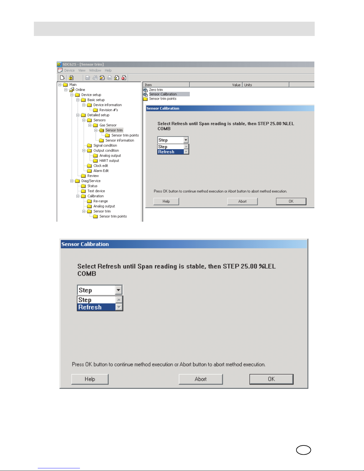
MSAStart-up and Calibration
ULTIMA XL/ULTIMA XT
60
GB
Span cal step screen
Fig. 16 Path: Span cal step screen
Fig. 17 Span cal step screen
Page 61
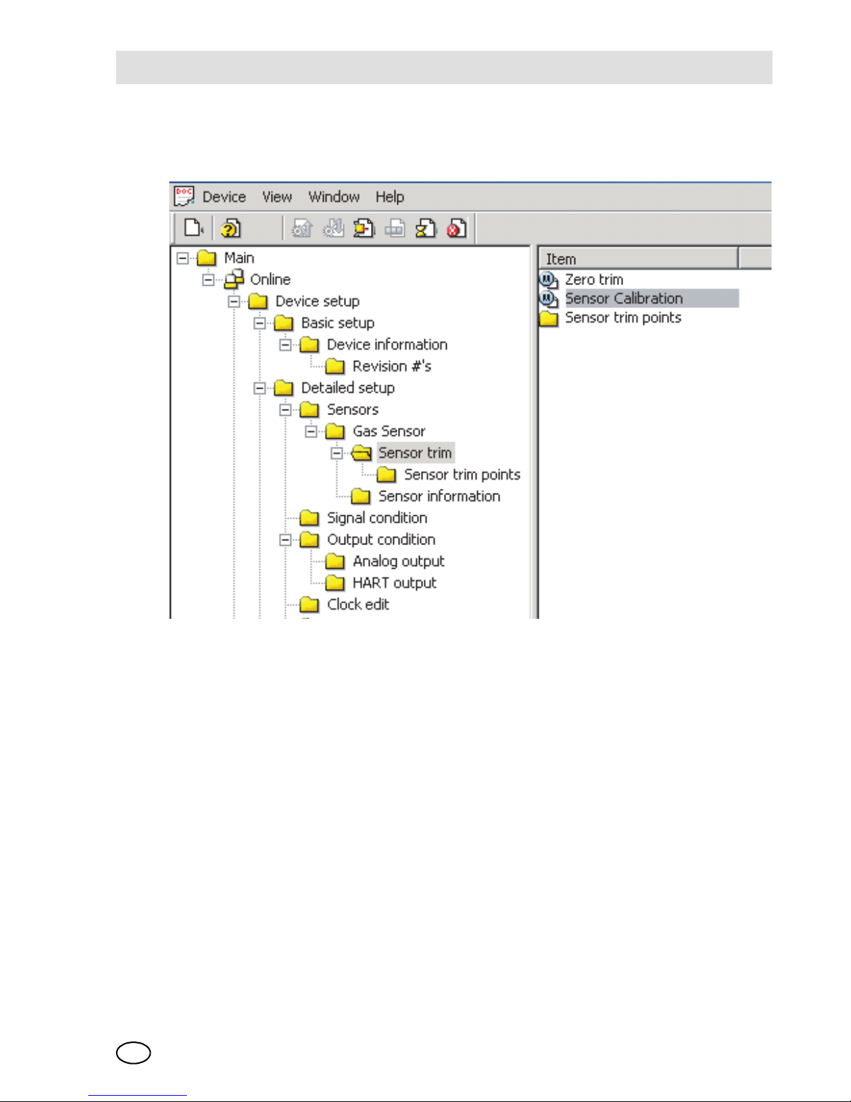
Start-up and CalibrationMSA
ULTIMA XL/ULTIMA XT
GB
61
3.14 Sample Calibration Display Screens
HART DDL-based calibration display screens
Fig. 18 Select Sensor Calibration from the Sensor Trim Menu
Page 62

MSAStart-up and Calibration
ULTIMA XL/ULTIMA XT
62
GB
First warning screen
Fig. 19 Path: First Warning screen
Fig. 20 First Warning screen
Page 63

Start-up and CalibrationMSA
ULTIMA XL/ULTIMA XT
GB
63
Second warning screen
Fig. 21 Path: Second Warning screen
Fig. 22 Second Warning screen
Page 64

MSAStart-up and Calibration
ULTIMA XL/ULTIMA XT
64
GB
Standard Calibration function select screen
Fig. 23 Path: Standard Calibration function select screen
Fig. 24 Standard Calibration function select screen
Page 65

Start-up and CalibrationMSA
ULTIMA XL/ULTIMA XT
GB
65
Calibration initiated screen
Fig. 25 Path: Calibration initiated screen
Fig. 26 Calibration initiated screen
Page 66

MSAStart-up and Calibration
ULTIMA XL/ULTIMA XT
66
GB
Selection Confirmation Screen
Fig. 27 Path: Selection Confirmation screen
Fig. 28 Selection Confirmation screen
Page 67

Start-up and CalibrationMSA
ULTIMA XL/ULTIMA XT
GB
67
Sensor Zero Countdown screen
Fig. 29 Path: Sensor Zero Countdown screen
Fig. 30 Sensor Zero Countdown screen
Page 68

MSAStart-up and Calibration
ULTIMA XL/ULTIMA XT
68
GB
Zero Adjustment screen
Fig. 31 Path: Zero Adjustment screen
Fig. 32 Zero Adjustment screen
Page 69

Start-up and CalibrationMSA
ULTIMA XL/ULTIMA XT
GB
69
Span countdown screen
Fig. 33 Path: Span countdown screen
Fig. 34 Span countdown screen
Page 70
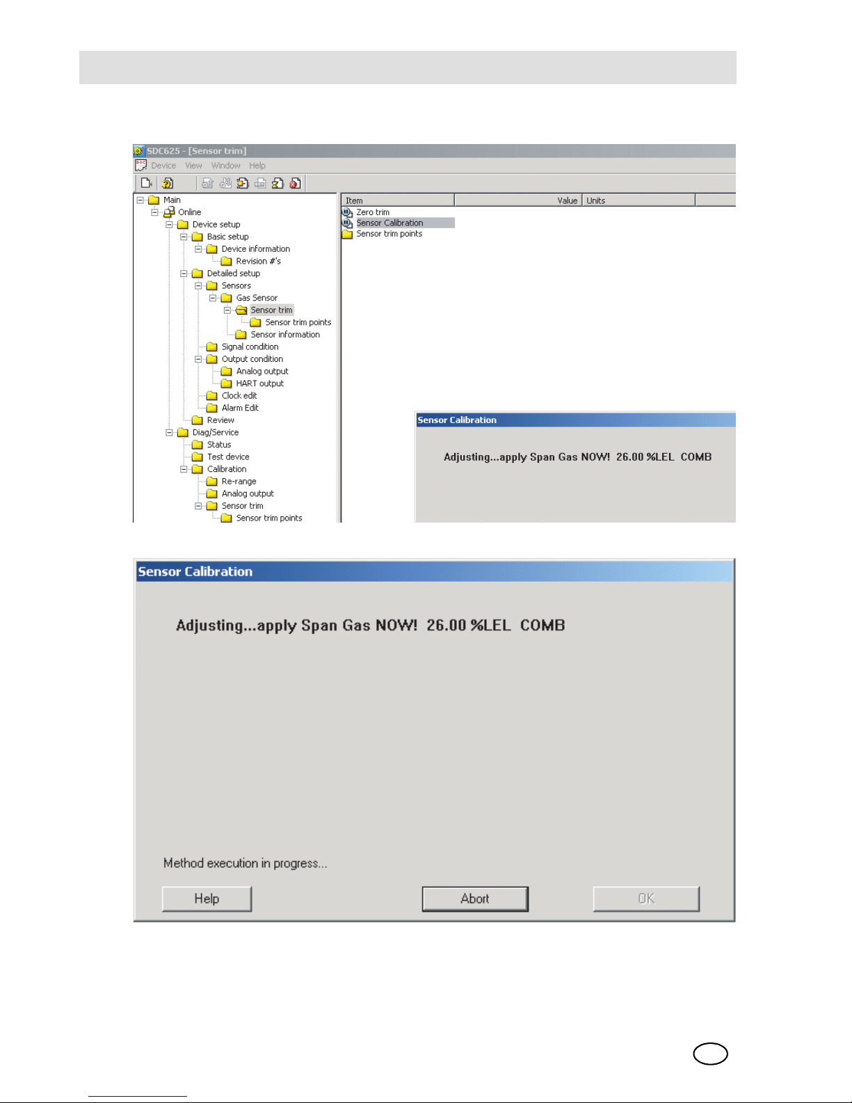
MSAStart-up and Calibration
ULTIMA XL/ULTIMA XT
70
GB
Adjusting Span screen
Fig. 35 Path: Adjusting Span screen
Fig. 36 Adjusting Span screen
Page 71
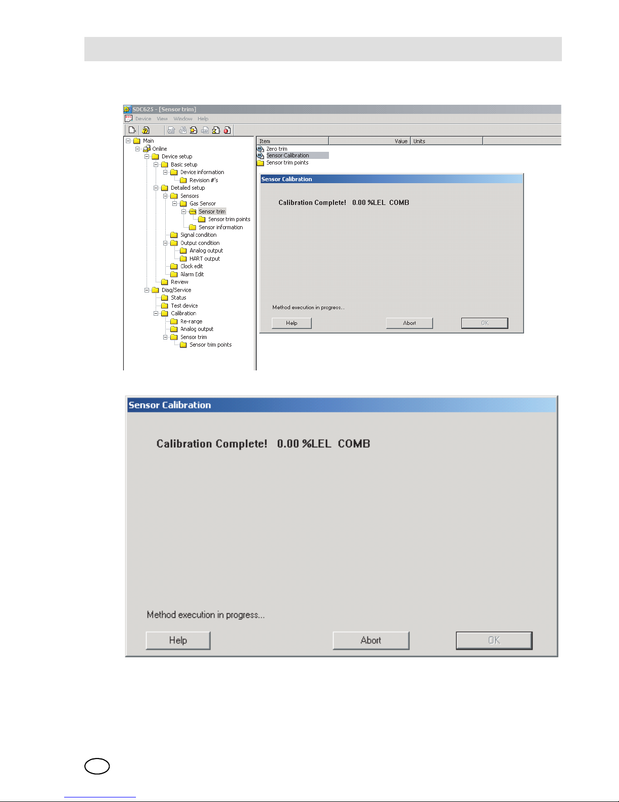
Start-up and CalibrationMSA
ULTIMA XL/ULTIMA XT
GB
71
Calibration completion message
Fig. 37 Path: Calibration completion message
Fig. 38 Calibration completion message
Page 72
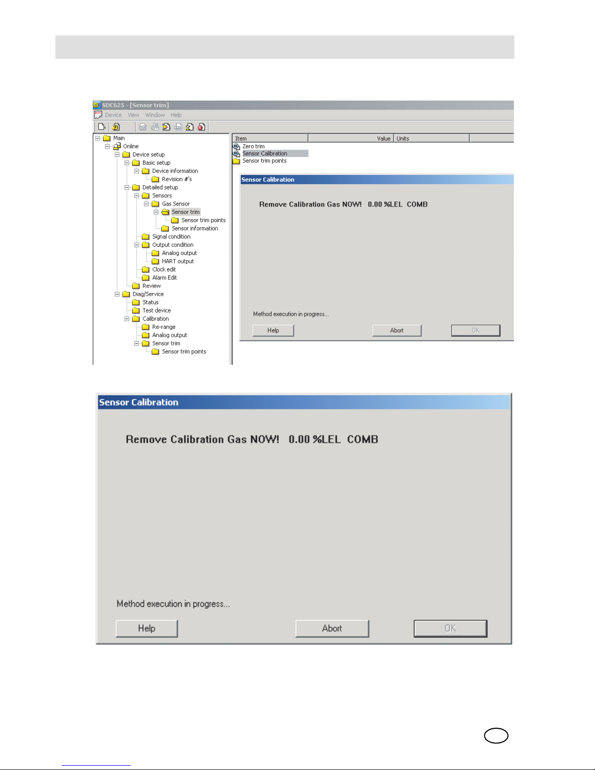
MSAStart-up and Calibration
ULTIMA XL/ULTIMA XT
72
GB
Calibration gas reminder screen
Fig. 39 Path: Calibration gas reminder screen
Fig. 40 Calibration gas reminder screen
Page 73

Start-up and CalibrationMSA
ULTIMA XL/ULTIMA XT
GB
73
Loop control reminder message
Fig. 41 Path: Loop control reminder message
Fig. 42 Loop control reminder message
Page 74

MSAStart-up and Calibration
ULTIMA XL/ULTIMA XT
74
GB
3.15 Troubleshooting
Fault indications
Span Fault
This fault can occur if the sensor is in cal mode and the required SPAN gas is not
applied to the sensor at the indicated time or within the timeout period. This fault
causes the 4-20 mA output to be set to the fault level [21 mA for Oxygen, 3 mA for
all other sensors]. This fault sets several status flags in the digital output to indicate
that an error has occurred. The current calibration status can be observed by rightclicking on status group 2 to expand it as shown in Æ Fig. 43.
Other possible cause for a Span Fault could be the use of an incorrect Span gas or
improperly set PV Upper Trim point [Span] setting. The Trim [calibration] point information can be viewed from the sensor trim points menu as shown in Æ Fig. 45.
Span faults can also be caused by a bad sensor, sensor at end-of-life, or a sensor
that is too far out of calibration for the Standard Zero/ Span procedure to make the
adjustment. An attempt to Initial Cal the sensor may be able to correct the calibration; otherwise, the sensor must be replaced. Additional sensor status can be obtained by right-clicking on status group 3 to expand it as shown in Æ Fig. 46.
Page 75

Start-up and CalibrationMSA
ULTIMA XL/ULTIMA XT
GB
75
Calibration status screen
Fig. 43 Path: Calibration status screen
Fig. 44 Calibration status screen
Page 76
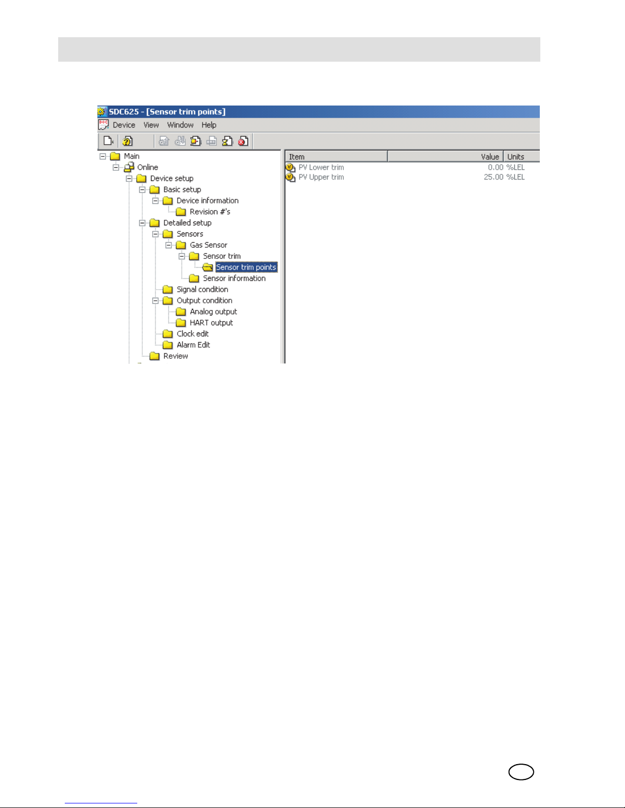
MSAStart-up and Calibration
ULTIMA XL/ULTIMA XT
76
GB
Sensor trim point screen
Fig. 45 Sensor trim point screen
Page 77

Start-up and CalibrationMSA
ULTIMA XL/ULTIMA XT
GB
77
Additional Sensor status screen
Fig. 46 Path: Additional Sensor status screen
Fig. 47 Additional Sensor status screen
Page 78

MSAStart-up and Calibration
ULTIMA XL/ULTIMA XT
78
GB
Zero Fault
The Zero Fault can be caused by a faulty sensor, calibration out of the Standard
Zero/Span calibration range, sensor in change, sensor fault or attempting to zero
the sensor with Span gas applied. The application of Zero gas should be checked
and the sensor status [as defined in Æ Fig. 43 and Æ Fig. 47] verified if this fault
occurs.
Calibration Aborted
User calibration abort or sensor calibration faults can cause a calibration process
to abort. Status group 2 as shown in Æ Fig. 43 can be viewed to determine if the
abort was caused by a cal fault. Status group 2 can be expanded by right-clicking
the selection as shown in Æ Fig. 48 to provide additional information
[also Æ Fig. 43]:
Page 79

Start-up and CalibrationMSA
ULTIMA XL/ULTIMA XT
GB
79
Device status screen
Fig. 48 Path: Device status screen
Fig. 49 Device status screen
Page 80

MSASpecifications
ULTIMA XL/ULTIMA XT
80
GB
4 Specifications
Specifications
Gas Types Combustibles, Oxygen & Toxics
Temperature
Range
Toxics &
Oxygen
Operating Range 0 to +40°C [32 to +104°F]
*Extended RangeE
-20 to +50°C [-4 to +122°F]
Operating Range
NH
3
0 to +30°C [32 to +86°F]
*Extended Range
NH3, Cl2, ClO
2
-10 to +40°C [-14 to +104°F]
Storage Temperature Range
-40 to +60°C [-40 to +140°F]
or limits of the sensor
Calibrate within operating range
Catalytic
Combustibles
Single Module
Dual Module
Toxics &
Oxygen
Single Module
Dual Module
Drift Zero Drift Less than 5%/year, typically
Span Drift Less than 10%/year, typically
Noise Less than 1% FS
*Extended Range = The sensor may not meet all of the accuracy parameters listed.
Page 81

SpecificationsMSA
ULTIMA XL/ULTIMA XT
GB
81
Accuracy
Gas Linearity Repeatability
Carbon Monoxide the greater of ±2%
full scale [FS]
±1% FS or 2 ppm
Oxygen 0 -25% v/v ±2% FS
0 -10% v/v ±3% FS
±1% FS
Hydrogen Sulfide ±10% FS or 2 ppm ±1% FS or 2 ppm
Chlorine ±10% FS or 2 ppm ±5% FS or 1 ppm
Sulfur Dioxide ±10% FS or 2 ppm ±1% FS or 2 ppm
Nitric Oxide ±10% FS or 2 ppm ±1% FS or 2 ppm
Nitrogen Dioxide ±10% FS or 2 ppm ± 4% FS or 1 ppm
Hydrogen Cyanide ±10% FS or 2 ppm ± 4% FS or 2 ppm
Hydrogen Chloride ±10% FS or 2 ppm ±10% FS or 2 ppm
Catalytic Combustible Gas <50% LEL +3% FS >50%
LEL +5% FS
±1% FS
±1% FS
IR Combustible Gas:
Methane; Propane
<50% LEL - +2% >50%
LEL - +5%
±2% FS
±2% FS
Chloride Dioxide ±10% FS or 2 ppm ±5% FS or 1 ppm
Ethylene Dioxide ±10% FS ±5% FS
Ammonia ±10% FS ±5% FS
Hydrogen ±5% FS ±5% FS
Phosphine ±10% FS ±10% FS
Arsine ±10% FS ±10% FS
Germane ±10% FS or 0.5 ppm ±10% FS
Silane ±10% FS or 2 ppm ±1% FS or 2 ppm
Diborane ±10% FS or 2 ppm ±1% FS or 2 ppm
Bromine ±10% FS or 2 ppm ±5% FS or 1 ppm
Page 82

MSASpecifications
ULTIMA XL/ULTIMA XT
82
GB
*)
Response time t90 may increase up to 50 seconds when used with SensorGard.
**)
SO2 sensor should not be used in dirty or humide environments.
***)
0 - 100 ppm NH3 sensor is consumable at a rate of 10% for every 200 ppm -
hours of exposure.
Step change
response
Time to reach 20 %
of scale - Oxygen &
Toxics
Less than 12 sec [typically 6 sec]
[typically 6 sec]
Less than 20 sec
Time to reach 50 %
of scale - Oxygen &
Toxics
Less than 30 sec [typically 12 sec]
[typically 12 sec]
Less than 45 sec
Response
time with
sensor
Gas ULTIMA XE Oxygen
t
20
t
90
Oxygen ≤ 10 sec ≤ 40 sec *)
Response
time with
sensor gard/
enviromental
gard
Gas
ULTIMA XEcom-
bustible
ULTIMA XIR
t
50
t90 t50t90
Methane ≤ 15 sec ≤ 35 sec ≤ 15 sec ≤ 35 sec
Propane ≤ 25 sec ≤ 55 sec ≤ 15 sec ≤ 45 sec
Ethylene ≤ 15 sec ≤ 40 sec
n-Pentane ≤ 30 sec ≤ 65 sec ≤ 15 sec ≤ 45 sec
Pressure 80 - 120 kPa XE: ≤ 8 % LEL Propane
Air velocity 0 - 6 m/s XE: ≤ 9 % LEL
Humidity Toxic gases and
oxygen
15 % to 95 % rel. humidity, non-condensing, max. 24 hours,
15% to 60% rel. humidity [SO
2
]
**)
35 % to 95 % rel. humidity, non-condensing, long-term
Combustible 5 % to 95 % rel. humidity
Sensor Life Combustible gases,
catalytic
3 years, typically
Toxic gases and
oxygen Ammonia
***)
2 years, typically
Full replacement
warranty
1 year from installation,10 years for IR
sensor source[see "MSA Instrument Warranty" in this manual for complete details]
Page 83

SpecificationsMSA
ULTIMA XL/ULTIMA XT
GB
83
Wiring Requirements
Oxygen,Toxics &
Combustibles
3-wire
Power Supply Oxygen & Toxics 24 VDC ±20 %,
55 mA max
Catalytic
Combustibles
24 VDC ±20 %,
350 mA max
IR Combustibles 24 VDC ±20 %,
530 mA max
Signal Output 4-20 mA Oxygen,Toxics &
Combustibles
3-wire current
source
XT Physical Size
Weight
238.58 mm x 157.25 mm x 75.54 mm
[9.39" x 6.19" x 2.97“]
0.79 kg [1.75 lbs.]
XL Physical Size
Weight
223.82 mm x 179.80 mm x 103.37 mm
[8.81" H x 7.08" W x 4.07"]
3.49 kg [7.7 lbs]
XL with IR Physical
Size
Weight
159.16 mm x 288.44 mm x 103.56 mm
[6.27“ H x 11.36" W x 4.08"]
3.64 kg [8.02 lbs.]
Page 84

MSASpecifications
ULTIMA XL/ULTIMA XT
84
GB
Sensor Response to Interferants
If your readings are higher or lower than expected, it could be due to the presence
of an interferant gas. The gas listed in column 1 is presented to the sensor. Column
2 indicates the concentration of that gas presented to the sensor. The remaining
columns indicate the respective responses by the sensors to each particular gas.
For Example: Scan column 1 until you locate "hydrogen". Column 2 shows that
500 ppm of hydrogen was presented to the sensor. Column 3 shows that a CO
[filtered] sensor gave an equivalent response of 200 ppm. Column 4 shows that an
H
2
S sensor gave an equivalent response of 0.5 ppm, etc.
Interferant
Concentration [ppm]
CO filtered
H
2
SCl
2
SO2 filtered
NO NO
2
Acetone 1000 0 0 0 0 ND 0
Acetylene 12000 0 0 0 0 ND ND
Ammonia 25 0 0 0 0 ND 0
Arsine 1 0 000 0ND
Benzene 20 0 0 0 0 ND ND
Bromine 2 0 0 2.5 ND 0 0
Carbon Dioxide
5000 0 0 0 0 0 0
Carbon Disulfide
15 0 000 0ND
Carbon Monoxide
100 100 0.3 0 0.2 ND 0
Chlorine 5 0 -3 5 0 0 0
Diborane 20 0 0 0 0 ND ND
Ethylene 50 100 0.1 0 0 ND 0
Ethyl Alcohol 100 115 0 0 0 ND ND
Ethyle Oxide 10 ND ND ND 0 ND ND
Ether 400 3 0 0 0 ND 0
Fluorine 5 0 0 2.5 0 0 ND
Freon 12 1000 0 0 0 0 0 0
Germane1 0 000 0ND
Hexane 500 0 0 0 0 ND 0
Hydrogen 500 200 0.5 0 15 ND -10
Page 85

SpecificationsMSA
ULTIMA XL/ULTIMA XT
GB
85
ND = No Data
Hydrogen
Chloride
50 0 000 40
Hydrogen
Cyanide
10 0 000 00
Hydrogen
Fluoride
10 0 0 0 0 ND ND
Hydrogen
Sulfide
10 1 10 -0.1 0 1 -8
MEK 200 0 000 00
Mercaptan
[Methyl]
504.5-0.101ND
Methane 5000 0 0 0 0 0 0
Nitric Oxide 100 0 2 0 2 100 ND
Nitrogen
Dioxide
5-1-40.5-51.55
Phosphine 0.5 ND 0 0 ND 0 ND
Silane 5 0 0 0 0 0 ND
Sulfur
Dioxide
10 0 0.3 0 10 0.5 ND
Tichloroethylene
1000 0 0 0 0 0 ND
Interferant
Concentration [ppm]
CO filtered
H
2
SCl
2
SO2 filtered
NO NO
2
Page 86
MSASpecifications
ULTIMA XL/ULTIMA XT
86
GB
Interferant
Concentration [ppm]
HCN HCL ClO2HF PH
3
ASH4SIH
4
Acetone 1000 ND ND 0 ND ND ND ND
Acetylene 12000 ND ND 0 ND ND ND ND
Ammonia25 0000NDNDND
Arsine 1 ND10ND0.711
Benzene 20 0 ND 0 ND ND ND ND
Bromine 2 0 ND 1 ND ND ND ND
Carbon Dioxide
5000 0 0 0 ND ND ND ND
Carbon Disulfide
15 0.100ND000
Carbon Monoxide
100 000ND010
Chlorine 5 -0.2 0 2.5 5 ND ND ND
Diborane20 ND00ND3.554
Ethylene 50 -0.3 ND 0 ND 0.5 1 1
Ethyl Alcohol 100 0 ND 0 ND ND ND ND
Ethyle Oxide 10 ND ND 0 ND ND ND ND
Ether 400 NDND0 NDNDNDND
Fluorine 5 0 0 1 ND ND ND ND
Freon 12 1000 0 0 0 0 0 0 0
Germane1 ND10ND0.711
Hexane 500 0 ND 0 ND ND ND ND
Hydrogen500 000ND000
Hydrogen
Chloride
50 ND50 0 30 NDNDND
Hydrogen
Cyanide
10 10 0 0 0 ND ND ND
Hydrogen
Fluoride
10 NDND0 NDNDNDND
Hydrogen
Sulfide
10 50 40 0 ND ND ND ND
MEK 200 NDND0 NDNDNDND
Page 87

SpecificationsMSA
ULTIMA XL/ULTIMA XT
GB
87
ND = No Data
Mercaptan
[Methyl]
5 6 ND0 NDNDNDND
Methane 5000 0 0 0 ND ND ND ND
Nitric Oxide 100 -3 40 0 2 ND ND ND
Nitrogen
Dioxide
5 ND 0 0.2 2.5 ND ND ND
Phosphine 0.5 ND 2 0 ND 0.5 1 0.7
Silane 5 ND 7 0 ND 0.1 0.2 5
Sulfur
Dioxide
10 -0.3 0 0 2.7 0.5 1 2
Tichloroethylene
1000 ND ND 0 ND ND ND ND
Interferant
Concentration [ppm]
GeH
3B2H6
Br
2
F
2
NH3NH
2
EtO
Acetone 1000 ND ND 0 0 ND ND ND
Acetylene 12000 ND ND 0 0 ND ND ND
Ammonia 25 ND ND 0 0 25 ND 0
Arsine 1 1 500NDNDND
Benzene 20 ND ND 0 0 ND ND ND
Bromine 2 ND ND 2 12 ND ND ND
Carbon Dioxide 5000 ND ND 0000ND
Carbon Disulfide 15 0 000NDNDND
Carbon
Monoxide
100 0 00002ND
Chlorine 5 ND ND 4 10 0 0 0
Diborane 20 5 20 0 0 ND ND ND
Ethylene 50 1 200040ND
Ethyl Alcohol 100 ND ND 0 0 ND ND 0
Ethyle Oxide 10 ND NDNDNDNDND10
Ether 400 ND ND 0 0 ND ND ND
Interferant
Concentration [ppm]
HCN HCL ClO
2
HF PH
3
ASH4SIH
4
Page 88

MSASpecifications
ULTIMA XL/ULTIMA XT
88
GB
ND = No Data
Fluorine 5 ND ND2 5 NDNDND
Freon 12 1000 0 000000
Germane 1 1 5 0 0 NDNDND
Hexane 500 ND ND 0 0 ND ND ND
Hydrogen 500 0 0 0 0 ND 500 0
Hydrogen
Chloride
50 NDND0000ND
Hydrogen
Cyanide
10 NDND00030
Hydrogen
Fluoride
10 ND ND0 0 NDNDND
Hydrogen
Sulfide
10 NDND0-0.20.51ND
MEK 200 NDND000ND3
Mercaptan
[Methyl]
5 ND ND 0 -0.2 ND ND ND
Methane 5000 ND ND 0 0 ND ND ND
Nitric Oxide 100 NDND0003ND
Nitrogen Dioxide 5 0.5 ND 0.4 1 ND ND 0
Phosphine 0.5 1 300000
Silane 5 0.2 15 0 0 ND ND ND
Sulfur Dioxide10 3 60000ND
Tichloroethylene 1000 ND ND ND 0 ND ND ND
Interferant
Concentration [ppm]
GeH
3B2H6
Br
2
F
2
NH
3
NH
2
EtO
Page 89

SpecificationsMSA
ULTIMA XL/ULTIMA XT
GB
89
4.1 HART Field Device Specification
The MSA ULTIMA XL/XT Gas Detection Instrument, revision 2, complies with
HART Protocol Revision 7 and uses the 16-bit manufacturer and device codes. This
document specifies all the device specific features and documents the HART Protocol implementation details [e.g., the Engineering Unit Codes supported].
This specification is a technical reference for HART-capable HOST Application Developers, System Integrators and knowledgeable End Users. It also provides functional specifications [e.g., commands, enumerations and performance
requirements] used during Field Device deployment, maintenance and testing.
These specifications assume the reader is somewhat familiar with HART Protocol
requirements and terminology.
Abbreviations and Definitions
HART Highway Addressable Remote Transducer
CPU Central Processing Unit
Echem Electrochemical
Pellistor catalytic style combustible sensor
IR Infrared
Page 90

MSASpecifications
ULTIMA XL/ULTIMA XT
90
GB
Device Identification
Fig. 50 ULTIMA XL Gas Monitor
4.2 Product Overview
The ULTIMA XL/XT Gas Monitor is an instrument used to detect and measure gas
concentrations. Detectable gases include Combustible and Toxic gas or Oxygen.
The HART-based ULTIMA XL/XT device uses various detection methods, depending on the gas of interest. Detection methods can be electrochemical, infrared, pellement or other technologies. The HART-based ULTIMA XL Gas Monitor is an and
flameproof device suitable for hazardous area applications. The HART-based
Manufacturer
Name
MSA Model Name [S] ULTIMA XL/XT
Manufacture
ID Code
0X6008 Device Type Code 0xe08c
HART Protocol
Revision
7 Device Revision 1
Number of Device
Variables
1 Notes:
Physical Layers
Supported
FSK, 4-20 mA
Physical Device
Category
Current Output
Page 91

SpecificationsMSA
ULTIMA XL/ULTIMA XT
GB
91
ULTIMA XT Gas Monitor is a general-purpose version in a plastic enclosure for use
in non-explosive atmospheres only.
4.3 Product Interfaces
Process Interface
Sensor Input channel
The main sensor input is provided via a five-terminal interface that provides a digital
interface for 3 VDC or 5 VDC sensor modules. Many different sensor modules are
available, providing sensing capability for a large variety of gases. The operating
range varies with the type of cell [e.g., electrochemical, pellistor or infrared combustible, etc.].
Host Interface
Analog Output
The three-wire 4-20 mA current loop is connected on terminals marked
8-30 VDC [1], 4-20 mA OUT[2], and GND [3-wire] [3]. Refer to the installation outline drawings for details.
This is the main output from this transmitter, representing the process gas measurement, linearized and scaled according to the configured instrument range. This
output corresponds to the Primary Variable [PV]. HART communications are supported on this loop. This device has a CN number of 1.
An inoperative device can be indicated by down-scale or up-scale current, depending on the sensor type. Current values are shown in the following table:
Current Values
Direction Values [% of Range] Values [mA or V]
Linear overrange
Down
Up
0%
+105.0% +1.0%
4.00 mA
20.64 to 20.96 mA
Device malfunction indication
Down: less than
Up: greater than
3.5 mA
20.96 mA
Maximum current
22.0 mA
Multi-drop Current draw
3.5 mA
Lift-off voltage 8 VDC
Page 92

MSASpecifications
ULTIMA XL/ULTIMA XT
92
GB
Local Interfaces, Jumpers and Switches
Local Controls and Displays
The ULTIMA XL/XT device has two dual-use LED indicators:
- one green "Normal" LED and
- one red "Alert" LED.
The ULTIMA XL/XT device has one multi-use pushbutton used for the following purposes:
- Acknowledge- single push acknowledgement to release latched alarms if
alarm level is no longer exceeded.
- Initiate Sensor Calibration- momentary push and release of the ACK/CAL button, followed by an immediate push and hold places the device into calibration
mode. See Chapter 3 for further details.
Internal Jumpers
This device has no internal jumpers.
Intrinsically Safe Communications Port
The ULTIMA XL explosion-proof/flameproof version of this device can be equipped
with an intrinsically safe communications port that can be used with a HART communications device that matches the parameters 6 [i.e. Emerson 375 or equivalent].
Page 93

SpecificationsMSA
ULTIMA XL/ULTIMA XT
GB
93
Device Variables Exposed by the ULTIMA XL/XT Monitor
Dynamic Variable implemented by ULTIMA XL/XT Monitor
Variable Description Variable Description
Gas Type Sensor gas type
description
Last Cal Date Date sensor was
last calibrated
Alarm Setpoints Gas value at which
an alarm status bit
is set
Auto Zero comp Amount of compen-
sated below zero
drift
Alarm Action increasing or de-
creasing alarm
type, latching or
non latching
Alert option status See next section
Alarm Status Indication of alarm
setpoint exceeded
Swap Delay status See next section
Input Voltage Device input volt-
age level
GT60 Ver Main Code Ver
Min/Max/Avg Minimum, maxi-
mum and avg. value of PV over time
Sensor Temp
Avg Interval Time interval for
min, max, avg [1, 8
or 24 hr]
Sensor Status Status returned by
sensor
Gas Table Linerization table
selection
RTC Date Device real time
clock date
RTC Min Device real time
clock minutes
RTC Hrs Device real time
clock hours
Meaning Units
PV Gas Value %, %LEL, PPM
Page 94

MSASpecifications
ULTIMA XL/ULTIMA XT
94
GB
Status Information
Device Status
Bit 4 ["More Status Available"] is set when any failure is detected. Command #48
gives further details.
Extended Device Status
The ULTIMA XL/XT Monitor can predict when certain maintenance will be required.
This bit is set if a sensor fault or maintenance warning is detected. "Device Variable
Alert" is set if the PV is out of limit.
Additional Device Status [Command #48]
Command #48 returns 5 bytes of data, with the following status information:
Byte Bit Meaning Class
Device Status Bits
Set
0 0 Configuration Reset Error 4,7
1 Main ram fault Error 4,7
2 Main flash fault Error 4,7
3 EEprom write error Error 4,7
4 Incompatible sensor Error 4,7
5 Sensor quick under
range
Error 4,7
6 Sensor UNDer range Error 4,7
7 Calibration fault Error 4,7
1 0 Sensor Missing Error 4,7
1 Sensor Overrange Warning
2 Overrange Lock Warning
3 Parameter Fault Error 4,7
4 Sensor Warm up Warning
5 Sensor Config Reset Warning
6 Sensor Power Fault Error
7 5V Power Fault Error
2 0 Zero Countdown Info
1 Apply Zero Gas Info
2 Span Countdown Info
3 Apply Span Gas Info
Page 95

SpecificationsMSA
ULTIMA XL/ULTIMA XT
GB
95
4 Cal Aborted Info
5 Zero Fault Info
6 Span Fault Info
7 Cal OK Info
3 0 End of Life Warning Warning 4,7
1 Sensor Swap Delay Info
2 Change Sensor Fault Error
3 Sensor Power Fault Error 4,7
4 Internal Comm Fault Error
5 Cal Sig Enable Info
6 Alert Option Enable Info
7Not Used
4 0 Alarm 1 Set Warning
1 Alarm 2 Set Warning
2 Alarm 3 Set Warning
3
4
5
6
7
"Not used" bits are always set to 0.
Some bits used in this transmitter indicate device or sensor failure and, therefore,
also set bit 7 and bit 4 of the Device Status byte.
These bits are set or cleared by the self-test executed at power up, or following a
reset. They are also set [but not cleared] by any failure detected during continuous
background self-testing.
Byte Bit Meaning Class
Device Status Bits
Set
Page 96

MSASpecifications
ULTIMA XL/ULTIMA XT
96
GB
4.4 Universal Commands
All Universal commands have been implemented in the ULTIMA XL/XT Gas Monitor. The ULTIMA XL/XT Gas Monitor returns a 7 in the Universal rev to indicate the
device is using the expanded 16-bit manufacturer and device codes.
4.5 Common-Practice Commands
The following Common Practice commands have been implemented in the
ULTIMA XL/XT device:
Supported Commands
Burst Mode
This device supports burst mode.
Catch Device Variable
This Field Device does not support Catch Device Variable.
Command # Description
35 Write Range Values
38 Reset “Configuration Changed” flag
40 Enter/Exit Fixed Current Mode
42 Perform Master Reset
45 Trim DAC Zero
46 Trim DAC Gain
48 Read Additional Device Status
59 Write Number of Response Preambles
71 Lock Device
72 Squawk
80 Read Device Variable Trim Point
Page 97

SpecificationsMSA
ULTIMA XL/ULTIMA XT
GB
97
Device-Specific Commands
Command # Description
129 Read Sensor Gas Type
130 Read Device RTC
131 Read Alarm Setpoints
132 Read Alarm Control Actions
133 Read Min/Max/Average Values
134 Read Last Cal Date
135 Read Gas Table
136 Read Input Voltage
137 Read Auto Zero Comp
138 Read Read GT60 Version
139 Read Sensor Status
140 Read Swap Delay Status
141 Read Cal Signal Status
142 Read Alert Option Status
143 Read Sensor Temperature
173 Write Device RTC
174 Write Alarm Setpoints
175 Write Alarm Control Actions
176 Write Average Interval
177 Write Upper Trim Point
178 Write Gas Table
179 Write Sensor Data sheet Reset
180 Write Sensor Swap Delay Enable
181 Write Cal Signal Enable
182 Write Calibration Mode
183 Write Calibration Abort
184 Write Calibration Step
185 Write Alarm Acknowledge
186 Write Protect Mode
187 Write Alert Option
Page 98

MSASpecifications
ULTIMA XL/ULTIMA XT
98
GB
Command #129: Read Sensor Gas Type
Reads the Gas Type of the sensor currently connected to the ULTIMA XL/XT
Gas Monitor.
Request Data Bytes
None.
Response Data Bytes
Command #130: Read Device Real Time Clock
Reads the Real Time clock hours and minutes from the ULTIMA XL/XT
Gas Monitor.
Request Data Bytes
None.
Response Data Bytes
Command #131: Read Alarm Setpoints
Reads the ULTIMA XL/XT Alarm Setpoint values.
Request Data Bytes
None.
Byte Format Description
0-3 ASCII Sensor gas type description
Byte Format Description
0 Unsigned RTC Hours
1 Unsigned RTC Minutes
Page 99
SpecificationsMSA
ULTIMA XL/ULTIMA XT
GB
99
Response Data Bytes
Command #132: Read Alarm Control Actions
Reads the ULTIMA XL/XT Alarm Control Actions.
Request Data Bytes
None.
Response Data Bytes
Command #133: Read Min, Max, Avg Values
Returns the ULTIMA XL/XT minimum, maximum and average values recorded over
an average interval. The average interval can be a value of 1, 8, or 24 hours. For a
one-hour interval, the value is updated at the top of each hour. For an eight-hour
interval, the values are updated at 800, 1600 and 2400 hours.
Request Data Bytes
None.
Response Data Bytes
Byte Format Description
0-3 Float Alarm 1 Setpoint Value
4-7 Float Alarm 2 Setpoint Value
8-11 Float Alarm 3 Setpoint Value
Byte Format Description
0 Bit Enum Alarm 1 Control Actions
1 Bit Enum Alarm 2 Control Actions
2 Bit Enum Alarm 3 Control Actions
Byte Format Description
0-3 Float Minimum Value
4-7 Float Maximum Value
8-11 Float Average Value
12 Unsigned Average interval [1, 8, or 24]
Page 100

MSASpecifications
ULTIMA XL/ULTIMA XT
100
GB
Command #134: Read Last Cal Date
Returns the ULTIMA XL/XT last calibration date of the currently connected sensor.
Request Data Bytes
None.
Response Data Bytes
Command #135: Read Gas Table
This command returns the ULTIMA XL/XT sensor Gas Table currently in use. The
Gas Tables are linearization reference tables used with certain sensors to provide
accurate response for different gases from the same sensor.
Request Data Bytes
None.
Response Data Bytes
Command #136: Read Input Voltage Value
Returns the ULTIMA XL/XT input supply voltage value. This number should be in
the range of 8-30 volts DC.
Request Data Bytes
None.
Response Data Bytes
Command #137: Read Auto Zero Comp Value
Returns the ULTIMA XL/XT Automatic Zero Compensation value. This value is accumulated by the device when the sensor reading attempts to drift below zero. This
value is used to compensate the actual Zero calibration. The device will attempt to
compensate up to 10 counts [display units] before setting the under-range bit.
Byte Format Description
0-2 Unsigned Last sensor calibration date
Byte Format Description
0 Unsigned Gas Table Number
Byte Format Description
0-3 Float Input Voltage Value
 Loading...