

MSA Ultima X, Ultima XE, Ultima XIR, Ultima XA Maintance Manual
Installation & Maintenance Instructions
Ultima® X Series Gas Monitors
Registered Address
ABLE Instruments & Controls Ltd
Cutbush Park, Danehill, Lower Earley,
Reading, Berk shire, RG6 4UT. UK.
Reading
Tel: +44 (0)118 9311188 | Email: info@able.co.uk
Aberdeen
Tel: +44 (0)1224 725999 | Email: ab@able.co.uk
Web
able.co.uk
E-commerce
247abl e.com
Ultima®X Series
Gas Monitors
Instruction Manual
In North America, to contact your nearest stocking location, dial toll-free 1-800-MSA-INST.
To contact MSA International, dial (724) 776-8626.
Inquiries can also be e-mailed to customer.service@msaSafety.com.
© MSA 2014 - All Rights Reserved
This manual is available on the internet at www.msaSafety.com
Manufactured by
MSA NORTH AMERICA
1000 Cranberry Woods Drive, Cranberry Township, PA 16066
(L) -Y Rev 9 10036101

THIS MANUAL MUST BE CAREFULLY READ BY ALL INDIVIDUALS WHO HAVE OR WILL
HAVE THE RESPONSIBILITY FOR USING OR SERVICING THE PRODUCT. Like any piece
of complex equipment, this instrument will perform as designed only if it is used and serviced in accordance with the manufacturer’s instructions. OTHERWISE, IT COULD FAIL TO
PERFORM AS DESIGNED AND PERSONS WHO RELY ON THIS PRODUCT FOR THEIR
SAFETY COULD SUSTAIN SEVERE PERSONAL INJURY OR LOSS OF LIFE.
The warranties made by Mine Safety Appliances Company with respect to the product are
voided if the product is not used and serviced in accordance with the instructions in this
manual. Please protect yourself and others by following them. We encourage our customers to write or call regarding this equipment prior to use or for any additional information relative to use or service.
MSA Instrument Warranty
1. Warranty- Seller warrants that this product will be free from
mechanical defect or faulty workmanship for the following periods:
• Gas Monitor: eighteen (18) months from date of shipment or
one (1) year from installation, whichever occurs first
• Oxygen, Toxic or Catalytic Combustible Sensor: eighteen (18)
months from date of shipment or one (1) year from installation,
whichever occurs first
• IR Sensor source: ten (10) years from date of shipment.
All other IR components: two (2) years from date of shipment.
This warranty is applicable provided the product is maintained and
used in accordance with Seller's instructions and/or
recommendations. This warranty does not apply to expendable or
consumable parts whose normal life expectancy is less than one
(1) year. The Seller shall be released from all obligations under this
warranty in the event repairs or modifications are made by persons
other than its own or authorized service personnel or if the
warranty claim results from physical abuse or misuse of the
product. No agent, employee or representative of the Seller has
any authority to bind the Seller to any affirmation, representation or
warranty concerning the goods sold under this contract. Seller
makes no warranty concerning components or accessories not
manufactured by the Seller, but will pass on to the Purchaser all
warranties of manufacturers of such components. THIS
WARRANTY IS IN LIEU OF ALL OTHER WARRANTIES,
EXPRESSED, IMPLIED OR STATUTORY, AND IS STRICTLY
LIMITED TO THE TERMS HEREOF. SELLER SPECIFICALLY
DISCLAIMS ANY WARRANTY OF MERCHANTABILITY OR OF
FITNESS FOR A PARTICULAR PURPOSE.
"! WARNING

NOTE: This equipment has been tested and found to comply with
the limits for a Class A digital device, pursuant to part 15 of
the FCC Rules. These limits are designed to provide reasonable protection against harmful interference when the
equipment is operated in a commercial environment. This
equipment generates, uses, and can radiate radio frequency energy and, if not installed and used in accordance with
the instruction manual, may cause harmful interference to
radio communications. Operation of this equipment in a
residential area is likely to cause harmful interference, in
which case the user will be required to correct the interference at his own expense.
This is a class A product in accordance with CISPR 22. In a
domestic environment, this product may cause radio interference, in which case the user may be required to take adequate measures.
2. Exclusive Remedy- It is expressly agreed that Purchaser's sole
and exclusive remedy for breach of the above warranty, for any
tortious conduct of Seller, or for any other cause of action, shall be
the repair and/or replacement at Seller's option, of any equipment
or parts thereof, which after examination by Seller is proven to be
defective. Replacement equipment and/or parts will be provided at
no cost to Purchaser, F.O.B. Seller's Plant. Failure of Seller to
successfully repair any nonconforming product shall not cause the
remedy established hereby to fail of its essential purpose.
3. Exclusion of Consequential Damage- Purchaser specifically
understands and agrees that under no circumstances will seller be
liable to purchaser for economic, special, incidental or
consequential damages or losses of any kind whatsoever, including
but not limited to, loss of anticipated profits and any other loss
caused by reason of nonoperation of the goods. This exclusion is
applicable to claims for breach of warranty, tortious conduct or any
other cause of action against seller.
"
WARNING
i

General Warnings and Cautions
1. The Ultima X Series Gas Monitors described in this manual must
be installed, operated and maintained in strict accordance with
their labels, cautions, warnings, instructions, and within limitations
stated. Verify that the class, group, and temperature ratings of the
equipment agree with the actual classification of the location.
2. The Ultima X Series Gas Monitor is designed to detect gases or
vapors in air. It cannot measure the concentration of gases or
vapors in steam or inert or oxygen-deficient atmospheres. The
oxygen sensor can measure oxygen-deficient atmospheres.
3. Electrochemical sensors are sealed units which contain a corrosive
electrolyte. Should a sensor develop leakage, it must be
immediately removed from service; then, remove it from the
sensing head and discard it properly. Caution must be exercised so
that the electrolyte does not contact skin, eyes, clothing or circuitry;
otherwise, serious personal injury (burns) and/or equipment
damage may result.
4. Use only genuine MSA replacement parts when performing any
maintenance procedures provided in this manual. Failure to do so
may seriously impair instrument performance. Repair or alteration
of the Ultima X Series Gas Monitor, beyond the scope of these
maintenance instructions or by anyone other than an authorized
MSA service personnel, could cause the product to fail to perform
as designed and persons who rely on this product for their safety
could sustain serious personal injury or loss of life.
5. Do not locate the general-purpose enclosure models in an area
which may contain a flammable mixture of gas and air; otherwise,
an explosion may occur. The general-purpose Ultima X Series Gas
Monitors can be a source of ignition and must not be mounted in
an area where a flammable mixture of combustible gas and air
may become present; otherwise, an explosion may occur. If such a
location must be monitored, use an explosion-proof Ultima X
Series Gas Monitor model.
6. The Ultima XIR Infrared combustible gas monitor detects the
presence of most combustible gases by identifying the difference in
the amount of infrared light energy absorbed during the presence
of these gases. This monitor, however, does NOT detect the
presence of hydrogen gas and must never be used to monitor for
hydrogen gas.
7. The standard Ultima XIR Infrared Combustible Gas Monitor does
"
WARNING
ii

not detect the presence of acetylene gas and the presence of
acetylene gas will degrade sensor performance. Custom-built
acetylene sensors are available through your MSA representative.
8. Gas detectors depend on an unimpeded gas flow for proper
operation. In environments where contamination is possible,
ensure that the flow remains unobstructed at the sensor. Failure to
follow this may prevent gas detection and generate inaccurate
readings.
9. CSA performance Certification to standard C22.2 No. 152 is valid
only when the instrument is calibrated on methane per the
instruction manual.
10. Install Product in accordance with all markings and the regulations
of the country in use.
11. Product components may have different hazardous location
ratings. Ensure all components are suitable for the area of
installation and protection technique.
Failure to follow the above can result in serious personal injury or loss of life.
1. As with all gas monitors of these types, high levels of, or long
exposure to, certain compounds in the tested atmosphere could
contaminate the sensors. In atmospheres where an Ultima X
Series Gas Monitor may be exposed to such materials, calibration
must be performed frequently to ensure that operation is
dependable and display indications are accurate.
2. The Ultima X Series Gas Monitor must not be painted. If painting is
done in an area where a Monitor is located, care must be
exercised to ensure that paint is not deposited on the sintered,
metal flashback arrestor in the inlet fitting of the Ultima X Series
Gas Monitor, if so equipped. Such paint deposits would interfere
with the diffusion process, whereby a sample of the atmosphere
being monitored diffuses into the Monitor.
3. The only absolute method to ensure proper overall operation of an
Ultima X Series Monitor is to check it with a known concentration
of the gas for which it has been calibrated. Consequently,
calibration checks must be included as part of the routine
inspection of the system.
4. Protect the Ultima X Series Gas Monitor from extreme vibration.
Do not mount the sensing head in direct sunlight as this may cause
overheating of the sensor.
Failure to follow the above can result in injury, product damage and/or an unsafe
condition.
"
CAUTION
iii

Table of Contents
Chapter 1,
Installation . . . . . . . . . . . . . . . . . . . . . . . . . . . . . .1-1
General Description . . . . . . . . . . . . . . . . . . . . . . . . . . . . . . . . .1-1
Identifying Your Unit . . . . . . . . . . . . . . . . . . . . . . . . . . . . . . . .1-1
Installing Your Gas Monitor . . . . . . . . . . . . . . . . . . . . . . . . . . .1-5
Installing the Ultima XA Gas Monitor . . . . . . . . . . . . . .1-6
Installing the Ultima XE Gas Monitor . . . . . . . . . . . . . .1-6
Installing the Ultima XIR Gas Monitor . . . . . . . . . . . . .1-8
Electrical Connections for Ultima X Gas Monitors . . . . . . . . .1-9
Wiring for all Models . . . . . . . . . . . . . . . . . . . . . . . . .1-10
Use of External Controllers . . . . . . . . . . . . . . . . . . . . . . . . . .1-12
Identify PCB Configuration . . . . . . . . . . . . . . . . . . . . . . . . . .1-13
Installing the Ultima X Remote Sensor Module . . . . . . . . . .1-20
Electrical Connections for Remote Sensors . . . . . . . . . . . . .1-21
Chapter 2,
Start-up and Calibration . . . . . . . . . . . . . . . . . . .2-1
Initial Start-up . . . . . . . . . . . . . . . . . . . . . . . . . . . . . . . . . . . . . .2-1
Calibration Basics . . . . . . . . . . . . . . . . . . . . . . . . . . . . . . . . . .2-4
Ultima Calibrator . . . . . . . . . . . . . . . . . . . . . . . . . . . . .2-6
Ultima Controller . . . . . . . . . . . . . . . . . . . . . . . . . . . . .2-6
Calibration Output Signal . . . . . . . . . . . . . . . . . . . . . . .2-6
Calibration Kit . . . . . . . . . . . . . . . . . . . . . . . . . . . . . . .2-7
Ultima X Series Gas Monitor Calibration Procedure . . . . . . . .2-7
Equipment Required . . . . . . . . . . . . . . . . . . . . . . . . . .2-8
Span Gas Values . . . . . . . . . . . . . . . . . . . . . . . . . . . . .2-9
INITIAL Calibration . . . . . . . . . . . . . . . . . . . . . . . . . . .2-12
Standard Calibration . . . . . . . . . . . . . . . . . . . . . . . . .2-13
OXYGEN Calibration . . . . . . . . . . . . . . . . . . . . . . . . .2-18
XIR Calibration . . . . . . . . . . . . . . . . . . . . . . . . . . . . . .2-18
iv

Chapter 3,
Specifications . . . . . . . . . . . . . . . . . . . . . . . . . . . .3-1
Chapter 4, Maintenance . . . . . . . . . . . . . . . . . . . .4-1
General . . . . . . . . . . . . . . . . . . . . . . . . . . . . . . . . . . . . . . .4-1
Ultima XIR Cleaning Procedure . . . . . . . . . . . . . . . . . . . . . . .4-4
Replacing an Ultima XE or Ultima XA Sensor . . . . . . . . . . . .4-5
Obtaining Replacement Parts . . . . . . . . . . . . . . . . . . . . . . . . .4-8
Appendix A,
Optional Features . . . . . . . . . . . . . . . . . . . . . . . .A-1
1) Internal Relays . . . . . . . . . . . . . . . . . . . . . . . . . . . . . . . . . .A-1
General Information . . . . . . . . . . . . . . . . . . . . . . . . . . .A-1
Unpacking, Mounting and Wiring . . . . . . . . . . . . . . . .A-1
Ultima X Series Gas Monitor Internal Relays . . . . . . .A-2
Relay Specifications . . . . . . . . . . . . . . . . . . . . . . . . . .A-2
Alarm Relays . . . . . . . . . . . . . . . . . . . . . . . . . . . . . . . .A-3
Fault Relay or Trouble . . . . . . . . . . . . . . . . . . . . . . . . .A-4
Relay Connections . . . . . . . . . . . . . . . . . . . . . . . . . . .A-5
2) Optional RESET Push-button . . . . . . . . . . . . . . . . . . . . . . .A-7
General . . . . . . . . . . . . . . . . . . . . . . . . . . . . . . . . . . . .A-7
RESET Button Selection . . . . . . . . . . . . . . . . . . . . . . .A-7
Optional Push-button Calibration . . . . . . . . . . . . . . . .A-8
3) Optional Horn Relay Software . . . . . . . . . . . . . . . . . . . . . .A-9
To Activate the Horn Relay . . . . . . . . . . . . . . . . . . . . .A-9
To Reset the Horn Relay . . . . . . . . . . . . . . . . . . . . . . .A-9
Appendix B,
Calibration Guide for Additional XIR/XI Gases .B-1
Appendix C,
General Certification Information . . . . . . . . . . .C-1
v

Appendix D,
HART Specific Information . . . . . . . . . . . . . . . . .D-1
HART Field Device Specification . . . . . . . . . . . . . . . . . . . . . .D-1
Host Interface . . . . . . . . . . . . . . . . . . . . . . . . . . . . . . .D-2
Status Information . . . . . . . . . . . . . . . . . . . . . . . . . . . .D-3
Extended Device Status . . . . . . . . . . . . . . . . . . . . . . .D-3
Universal Commands . . . . . . . . . . . . . . . . . . . . . . . . .D-5
Common-Practice Commands . . . . . . . . . . . . . . . . . .D-5
Burst Mode . . . . . . . . . . . . . . . . . . . . . . . . . . . . . . . . .D-6
Catch Device Variable . . . . . . . . . . . . . . . . . . . . . . . . .D-6
Command #129: Read Sensor Gas Type . . . . . . . . . .D-7
Command #130: Read Device Real Time Clock . . . .D-7
Command #131: Read Alarm Setpoints . . . . . . . . . . .D-8
Command #132: Read Alarm Control Actions . . . . . .D-9
Command #133: Read Min, Max, Avg Values . . . . . .D-9
Command #134: Read Last Cal Date . . . . . . . . . . . .D-10
Command #135: Read Gas Table . . . . . . . . . . . . . . .D-10
Command #136: Read Input Voltage Value . . . . . . .D-10
Command #137: Read Auto Zero Comp Value . . . .D-11
Command #139: Read Sensor Status message . . . .D-11
Command #140: Read Swap Delay Status . . . . . . .D-11
Command #141: Read Cal Signal Status . . . . . . . . .D-12
Command #142: Read Alert Option Status . . . . . . . .D-12
Command #143: Read Sensor Temperature . . . . . .D-13
Command #144: Read Relay Normal State . . . . . . .D-13
Command #173: Write RTC . . . . . . . . . . . . . . . . . . .D-14
Command #174: Write Alarm Setpoints . . . . . . . . . .D-15
Command #175: Write Alarm Setpoint
Control Actions . . . . . . . . . . . . . . . . . . . . . . . . . . . . .D-16
Command #176: Write Average Interval . . . . . . . . . .D-17
Command #177: Write Upper Trim Point . . . . . . . . .D-18
Command #178: Write Gas Table . . . . . . . . . . . . . . .D-19
Command #179: Write Sensor Data Sheet
Reset Control . . . . . . . . . . . . . . . . . . . . . . . . . . . . . .D-20
Command #180: Write Sensor Swap Delay Enable .D-21
Command #181: Write Cal Signal Enable . . . . . . . .D-22
Command #182: Write Calibration Mode . . . . . . . . .D-23
Command #183: Write Calibration Abort . . . . . . . . .D-24
Command #184: Write Calibration Step . . . . . . . . . .D-25
vi

Command #185: Write Alarm Acknowledge . . . . . . .D-26
Command #186: Write Protect Mode . . . . . . . . . . . .D-27
Command #187: Write Alert Option . . . . . . . . . . . . .D-28
Command #188: Write Relay Normal State . . . . . . .D-29
Performance . . . . . . . . . . . . . . . . . . . . . . . . . . . . . . .D-32
Power-Up . . . . . . . . . . . . . . . . . . . . . . . . . . . . . . . . .D-32
Reset . . . . . . . . . . . . . . . . . . . . . . . . . . . . . . . . . . . . .D-32
Self-Test . . . . . . . . . . . . . . . . . . . . . . . . . . . . . . . . . .D-32
Busy and Delayed-Response . . . . . . . . . . . . . . . . . .D-33
Long Messages . . . . . . . . . . . . . . . . . . . . . . . . . . . . .D-33
Non-Volatile Memory . . . . . . . . . . . . . . . . . . . . . . . . .D-33
Modes . . . . . . . . . . . . . . . . . . . . . . . . . . . . . . . . . . . .D-34
Write Protection . . . . . . . . . . . . . . . . . . . . . . . . . . . . .D-34
Damping . . . . . . . . . . . . . . . . . . . . . . . . . . . . . . . . . .D-34
Capability Checklist . . . . . . . . . . . . . . . . . . . . . . . . . . . . . . . .D-34
Default Configuration . . . . . . . . . . . . . . . . . . . . . . . . . . . . . .D-35
Calibration Using a HART® Communicator . . . . . . . . . . . . .D-35
Sensor Zero Selection Menu . . . . . . . . . . . . . . . . . .D-35
Standard Zero/Span Calibration Selection Menu . . .D-37
Initial Calibration Procedures . . . . . . . . . . . . . . . . . .D-40
User Calibration Selection Menu . . . . . . . . . . . . . . .D-40
Troubleshooting . . . . . . . . . . . . . . . . . . . . . . . . . . . . . . . . . .D-54
Span Fault . . . . . . . . . . . . . . . . . . . . . . . . . . . . . . . . .D-54
Zero Fault . . . . . . . . . . . . . . . . . . . . . . . . . . . . . . . . .D-57
vii

List of Figures
Figure 1-1. General-Purpose Ultima XA Monitor . . . . . . . . . .1-1
Figure 1-2. -Proof Ultima XE Monitor . . . . . . . . . . . . . . . . . . .1-2
Figure 1-3. Explosion-Proof Ultima XIR Monitor . . . . . . . . . . .1-2
Figure 1-4. General-Purpose XA Remote Sensor Module . . .1-3
Figure 1-5. Explosion-Proof XE Remote Sensor Module . . . .1-3
Figure 1-6. Explosion-Proof XIR Remote Sensor Module . . .1-4
Figure 1-7. Ultima XE and XIR Mounting Bracket . . . . . . . . .1-7
Figure 1-8. Ultima XIR . . . . . . . . . . . . . . . . . . . . . . . . . . . . . . .1-8
Figure 1-9. Ultima XE Grounding Terminals . . . . . . . . . . . . . .1-9
Figure 1-10. General-Purpose Two-Wire Operation . . . . . . .1-14
Figure 1-11. Explosion-Proof Two-Wire Operation . . . . . . . .1-14
Figure 1-12. General-Purpose Three-Wire Operation . . . . . .1-15
Figure 1-13. Explosion-Proof Three-Wire Operation . . . . . . .1-15
Figure 1-14. Two-Wire Printed Circuit Board
(no HART Protocol) . . . . . . . . . . . . . . . . . . . . . .1-16
Figure 1-15. Two-Wire Printed Circuit Board
(with HART Protocol) . . . . . . . . . . . . . . . . . . . . .1-17
Figure 1-16. Three-Wire Printed Circuit Board
(no HART Protocol) . . . . . . . . . . . . . . . . . . . . . .1-18
Figure 1-17. Three-Wire Printed Circuit Board
(with HART Protocol) . . . . . . . . . . . . . . . . . . . . .1-19
Figure 1-18. Remote Module General-Purpose
Ultima X Series Wiring . . . . . . . . . . . . . . . . . . . .1-20
Figure 1-19. Remote Module Explosion-Proof
Ultima X Series Wiring . . . . . . . . . . . . . . . . . . . .1-20
Figure 2-1. LCD Gas Concentration Display . . . . . . . . . . . . . .2-1
Figure 2-2. Ultima Calibrator . . . . . . . . . . . . . . . . . . . . . . . . . .2-5
Figure 2-3. Ultima Controller . . . . . . . . . . . . . . . . . . . . . . . . . .2-5
Figure 2-4. Ultima X Optional Push-button Calibrator . . . . . . .2-5
Figure 2-5. Apply ZERO Gas Flag . . . . . . . . . . . . . . . . . . . .2-14
Figure 2-6. Apply SPAN Gas Flag . . . . . . . . . . . . . . . . . . . . .2-15
Figure 2-7. Calibration End Display . . . . . . . . . . . . . . . . . . .2-17
Figure 4-1. "Change Sensor" Scrolls Across the Display . . . .4-6
Figure 4-2. Sensor Assembly and Sensor Guard
for General-Purpose Model . . . . . . . . . . . . . . . . .4-7
Figure A-1. Relay Contacts . . . . . . . . . . . . . . . . . . . . . . . . . . .A-4
Figure A-2. Relay Printed Circuit Board . . . . . . . . . . . . . . . . .A-6
Figure D-1. Zero cal step screen . . . . . . . . . . . . . . . . . . . . .D-41
viii

Figure D-2. Span cal step screen . . . . . . . . . . . . . . . . . . . . .D-41
Figure D-3. Select Sensor Calibration
from the Sensor Trim Menu . . . . . . . . . . . . . . . .D-42
Figure D-4. First Warning screen . . . . . . . . . . . . . . . . . . . . .D-43
Figure D-5. Second Warning screen . . . . . . . . . . . . . . . . . .D-44
Figure D-6. Standard Calibration function select screen . . .D-45
Figure D-7. Calibration initiated screen . . . . . . . . . . . . . . . .D-46
Figure D-8. Selection Confirmation screen . . . . . . . . . . . . . .D-47
Figure D-9. Sensor Zero Countdown screen . . . . . . . . . . . .D-48
Figure D-10. Zero Adjustment screen . . . . . . . . . . . . . . . . . .D-49
Figure D-11. Span Countdown screen . . . . . . . . . . . . . . . . .D-50
Figure D-12. Adjusting Span screen . . . . . . . . . . . . . . . . . . .D-51
Figure D-13. Calibration Completion message . . . . . . . . . . .D-52
Figure D-14. Calibration Gas Reminder screen . . . . . . . . . .D-53
Figure D-15. Loop Control Reminder message . . . . . . . . . .D-54
Figure D-16. Calibration Status screen . . . . . . . . . . . . . . . . .D-55
Figure D-17. Sensor Trim Point screen . . . . . . . . . . . . . . . .D-56
Figure D-18. Additional Sensor Status screen . . . . . . . . . . .D-57
Figure D-19. Device Status screen . . . . . . . . . . . . . . . . . . . .D-58
ix

List of Tables
Table 1-1. Installation Outline Drawing List . . . . . . . . . . . . . .1-10
Table 1-2. Cable Length and Wire Size for Units without
Internal Relays . . . . . . . . . . . . . . . . . . . . . . . . . .1-11
Table 1-3. Installation Outline Drawings
for Ultima X Power Supplies . . . . . . . . . . . . . . .1-12
Table 1-4. Remote Module Wiring and Placement . . . . . . . .1-22
Table 1-5. Remote Sensor Wiring Cable . . . . . . . . . . . . . . . .1-22
Table 1-6. Low Temperature Wiring Cable . . . . . . . . . . . . . .1-22
Table 2-1. Instrument Operation . . . . . . . . . . . . . . . . . . . . . . .2-2
Table 2-2. Factory-set Span Values . . . . . . . . . . . . . . . . . . . .2-9
Table 2-3. Calibration Guide for Combustible Gas Sensor . .2-11
Table 3-1. Performance Specifications . . . . . . . . . . . . . . . . . .3-1
Table 3-2. Sensor Response to Interferants . . . . . . . . . . . . . .3-4
Table 4-1. Operational Display Messages . . . . . . . . . . . . . . . .4-1
Table 4-2. Configuration Display Messages . . . . . . . . . . . . . .4-2
Table 4-3. Troubleshooting Guidelines . . . . . . . . . . . . . . . . . .4-2
Table 4-4. Replacement Parts . . . . . . . . . . . . . . . . . . . . . . . . .4-8
Table A-1. Power Cable Distances for the Ultima X
Series Gas Monitor with Internal Relays . . . . . .A-2
Table A-2. Relay Specifications . . . . . . . . . . . . . . . . . . . . . . . .A-2
Table A-3. Push-button Calibration . . . . . . . . . . . . . . . . . . . . .A-8
Table D-1. Device Identification . . . . . . . . . . . . . . . . . . . . . . .D-1
Table D-2. Current Values . . . . . . . . . . . . . . . . . . . . . . . . . . . .D-2
Table D-3. Device Variables Exposed by the Ultima Monitor .D-3
Table D-4. Dynamic Variable implemented by Ultima Monitor D-3
Table D-5. Additional Device Status (Command #48) . . . . . .D-4
Table D-6. Supported Commands . . . . . . . . . . . . . . . . . . . . .D-6
Table D-7. Device-Specific Commands . . . . . . . . . . . . . . . . .D-7
Table D-8. Gas Type Descriptions . . . . . . . . . . . . . . . . . . . .D-30
Table D-9. Alarm Control Actions . . . . . . . . . . . . . . . . . . . . .D-30
Table D-10. Gas Table Values . . . . . . . . . . . . . . . . . . . . . . .D-30
Table D-11. Calibration Modes . . . . . . . . . . . . . . . . . . . . . . .D-31
Table D-12. Sensor Status Codes . . . . . . . . . . . . . . . . . . . .D-31
Table D-13. Sampling Rates . . . . . . . . . . . . . . . . . . . . . . . . .D-32
Table D-14. Command Response Times . . . . . . . . . . . . . . .D-33
Table D-15. Capability Checklist . . . . . . . . . . . . . . . . . . . . . .D-34
Table D-16. Default Configuration . . . . . . . . . . . . . . . . . . . .D-35
x
1-1
Chapter 1,
Installation
General Description
The Ultima X Series Gas Monitor is designed to sample the
environment where mounted and alert you to potentially dangerous
levels of your target gas, depending on your particular model. The
Ultima X Series device uses various detection methods, depending on
the gas of interest. Detection methods can be electrochemical, infrared,
pellement or other technologies. The Ultima XE Gas Monitor is an
explosion-proof device suitable for installation in hazardous locations.
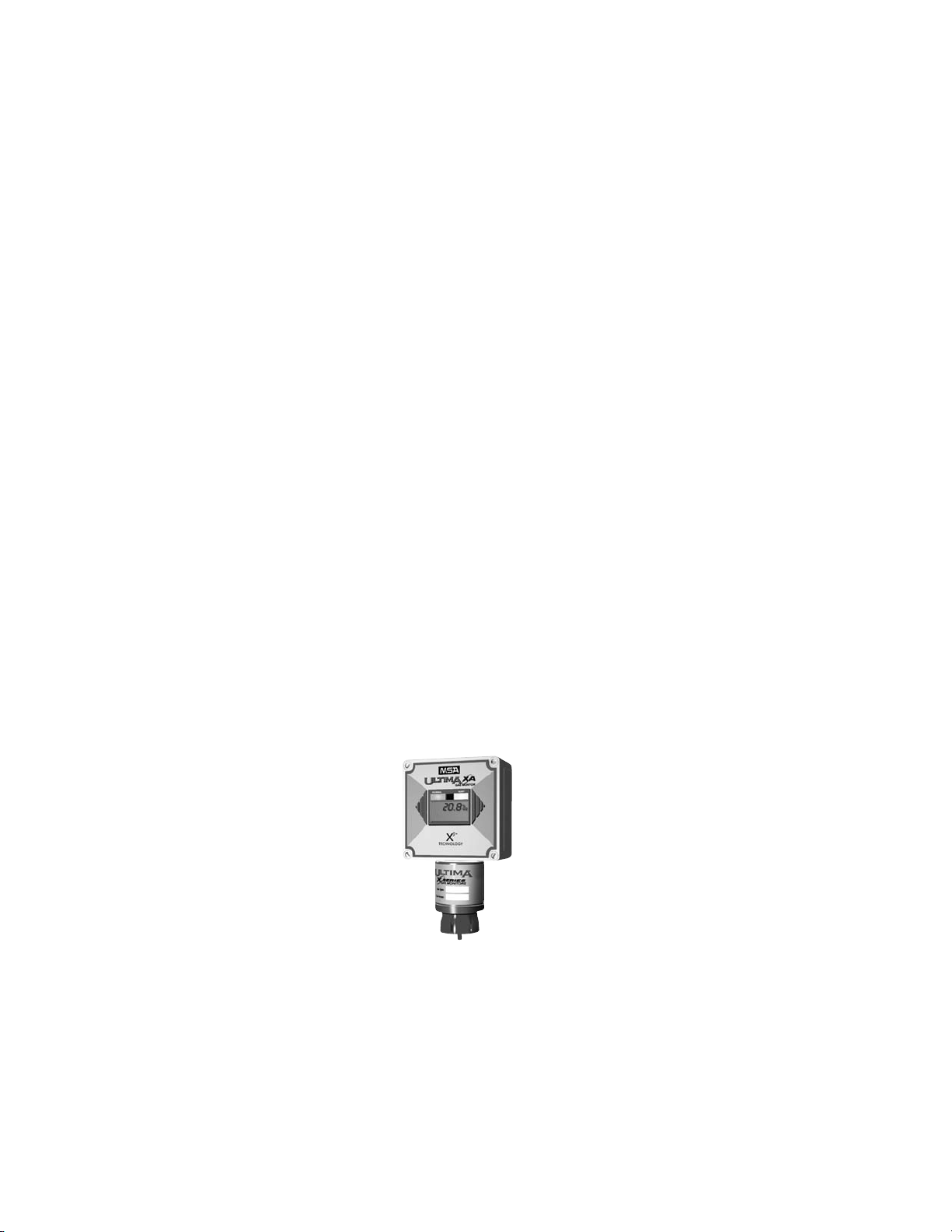
The Ultima XA Gas Monitor is a general-purpose version in a plastic
enclosure for use in nonexplosive atmospheres only. The Ultima X Gas
Monitor can be ordered with the standard 4 to 20 mA analog output or
with an optional HART (Highway Addressable Remote Transducer)
protocol, which is superimposed on the 4 to 20 mA signal. The unit is
factory-calibrated and shipped ready for installation.
The main sensor input is provided via a five-terminal interface that
provides a digital interface for 3 VDC or 5 VDC sensor modules. Many
different sensor modules are available, providing sensing capability for a
large variety of gases. The operating range varies with the type of cell
(e.g., electrochemical, pellistor or infrared combustible, etc.).
Identifying Your Unit
The Ultima XA Gas Monitor is housed in a rugged, plastic generalpurpose enclosure (FIGURE 1-1).
Figure 1-1. General-Purpose Ultima XA Monitor
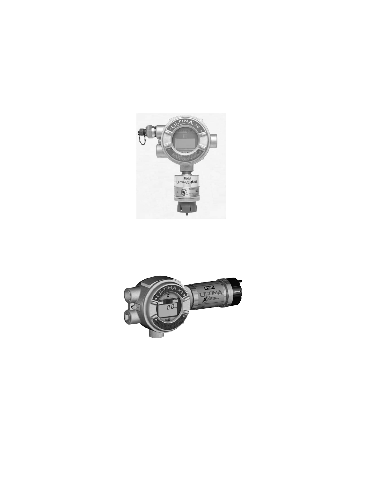
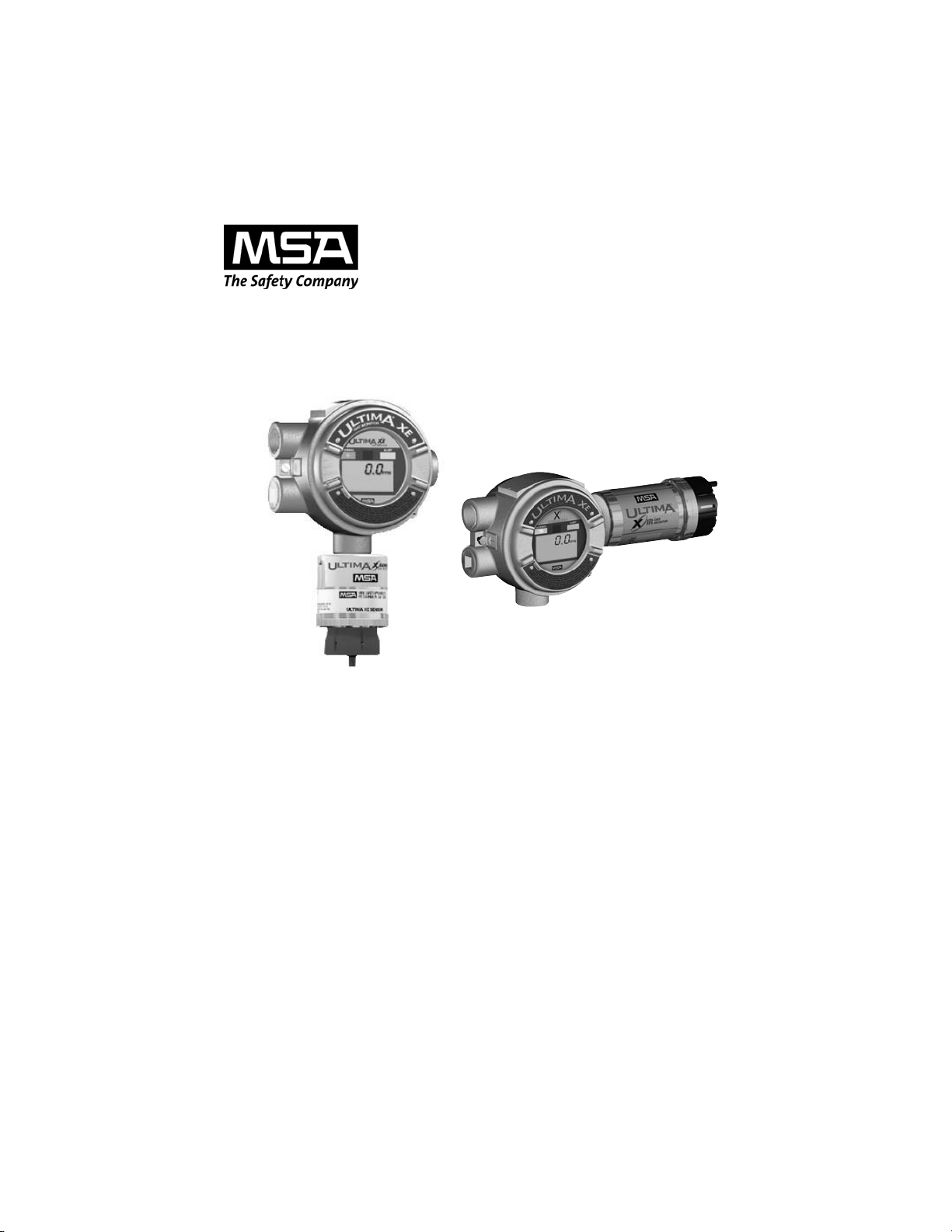
The Ultima XE Gas Monitor is housed in a 316 stainless steel
explosion-proof enclosure (FIGURE 1-2 shows the Ultima XE
with the optional explosion-proof HART port).
.
The Ultima XIR Gas Monitor is housed in a 316 stainless steel
explosion-proof enclosure (FIGURE 1-3).
If your application requires the sensor head to be located separately
from the control unit, all models are available with Remote Sensor
Modules (shown in FIGURES 1-4, 1-5 and 1-6).
Figure 1-3. Explosion-Proof Ultima XIR Monitor
Figure 1-2. Explosion-Proof Ultima XE Monitor
1-2
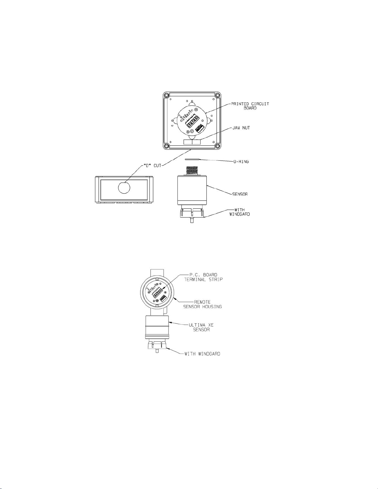
Figure 1-5. Explosion-Proof XE Remote Sensor Module
Figure 1-4. General-Purpose XA Remote Sensor Module
1-3
To determine your sensor type and options, check the shipping carton.
Checked items are included in the carton. The carton label identifies:
• Type of unit supplied (Gas Monitor, Gas Monitor Less Sensor, or
Remote Sensor Module)
• Type of gas (combustible gas, toxic gas or oxygen)
• Range [% LEL, PPM (parts per million), or %]
• Output (2- or 3-wire, 4 to 20 mA, or 4 to 20 mA with HART)
• Any options such as internal relays and/or LEDs.
• If your unit contains internal relays, see Appendix A.
Also check the sensor ID label located on the inside of the sensor. This
can be viewed by unscrewing the lower portion of the sensor. If
performing this while the unit is powered, see the following Warning.
The sensor ID label identifies the detectable gas and the gas range.
For Ultima XE sensors marked Class I, Groups A, B, C and D
and not used in Class II areas, unscrew sensor cap at least
three full turns (but no more than four full turns from its
tightly-closed position), wait 10 seconds, and then remove
cap completely. Failure to follow this warning can result in
the ignition of a hazardous atmosphere.
For the Ultima XE Sensor marked Class II Groups F and G,
atmosphere must be free of dust and the power removed
from the unit before the sensor cap can be removed from the
housing. Failure to follow this warning can result in the ignition of a hazardous atmosphere.
"
WARNING
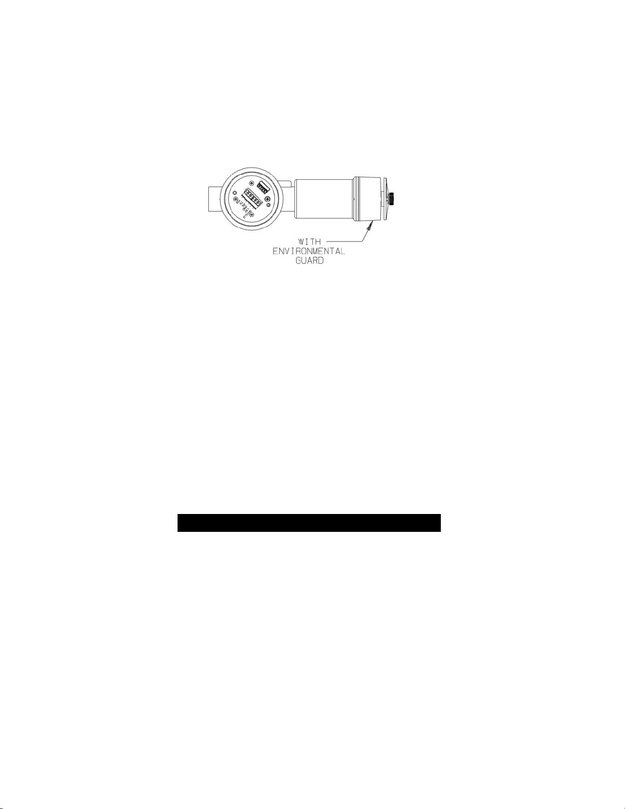
Figure 1-6. Explosion-Proof XIR Remote Sensor Module
1-4

Your Ultima XE Series Gas Monitor may also include a separate HART
Module if you ordered the following optional accessories:
1). Internal Power Supply and explosion-proof HART Port
2). External RESET Push-button and explosion-proof HART Port.
Installing Your Gas Monitor
NOTE: Reference installation outline drawings listed in TABLE 1-1.
Generally, the Ultima X Series Gas Monitors or remote sensing
module should be mounted close to the area where a leak is likely to
occur or where the gas is expected. Install the Ultima X Series Gas
Monitors or the remote sensing module at a high level (ceiling) or low
level (floor), depending on the density of the gas most likely to be
found. Install the unit so that the front display of the unit is not blocked
or hidden from view.
Mount the Ultima XE or XA Gas Monitor or remote sensing
module with the sensor inlet fitting (FIGURE 1-1, 1-2, 1-4 or
1-5) pointed downward; otherwise, the inlet may become
clogged with particulate matter or liquids.
Mount the Ultima XIR Gas Monitor or XIR Remote Sensing
Module with the sensor inlet fitting extended horizontally
from the main enclosure (FIGURE 1-3 and 1-6) to prevent the
build-up of particulate or liquid matter on the monitor's optical surfaces.
Do not paint the Ultima X Series Gas Monitors. If painting is
done in an area where a sensor is located, exercise CAUTION to ensure paint is not deposited on the sensor inlet fitting. Such paint deposits would interfere with the diffusion
process, whereby a sample of the monitored atmosphere
diffuses into the sensor. In addition, solvents in the paint
may cause an alarm condition to occur.
Protect the Ultima X Series Gas Monitors from extreme
vibration. Do not mount sensing head in direct sunlight as
this may cause overheating of the sensor.
"
CAUTION
1-5

Do not locate the general-purpose enclosure models in an
area which may contain a flammable mixture of gas and air;
otherwise, an explosion may occur. The general-purpose
Ultima X Series Gas Monitors can be a source of ignition and
must not be mounted in an area where a flammable mixture
of combustible gas and air may become present; otherwise,
an explosion may occur. If such a location must be monitored, use an explosion-proof gas monitor.
Installing the Ultima XA Gas Monitor
Remove lid and drill enclosure for power, signal and optional relay cable
entry. Use one of the following methods to mount the general-purpose
Ultima XA Gas Monitor/Less Sensor or the Ultima XA Gas Monitor.
• Using customer-installed wiring holes, install the Ultima XA Gas
Monitor to the end of rigid conduit.
• Use mounting holes in the corners of the Ultima XA enclosure to
mount directly to a wall.
• Use mounting holes in the corners of the Ultima XA enclosure to
mount to the optional Mounting Kit (P/N 10047561);
see FIGURE 1-7.
• The Ultima XA gas sensor is not shipped attached to the main
enclosure. Ensure the sensor wiring harness is through the entry
and the sensor is pointed downward.
Installing the Ultima XE Gas Monitor
• The optional Mounting Bracket Kit (P/N 10047561) can be attached
to the rear holes of the Ultima XE Gas Monitor (FIGURE 1-7).
• The Ultima XE Gas Monitor main enclosure can be rotated 360°
and mounted to ensure easy access to any of the four entryways.
The electronics assembly inside the metal enclosure can be
repositioned in any of the four self-aligning interior holes to ensure
the display is properly oriented.
• The Ultima XE Gas Monitor sensor is not shipped attached to the
main enclosure. Ensure the sensor wiring harness is through the
entry and the sensor is pointing downward. Tighten with a strap
wrench.
"
WARNING
1-6
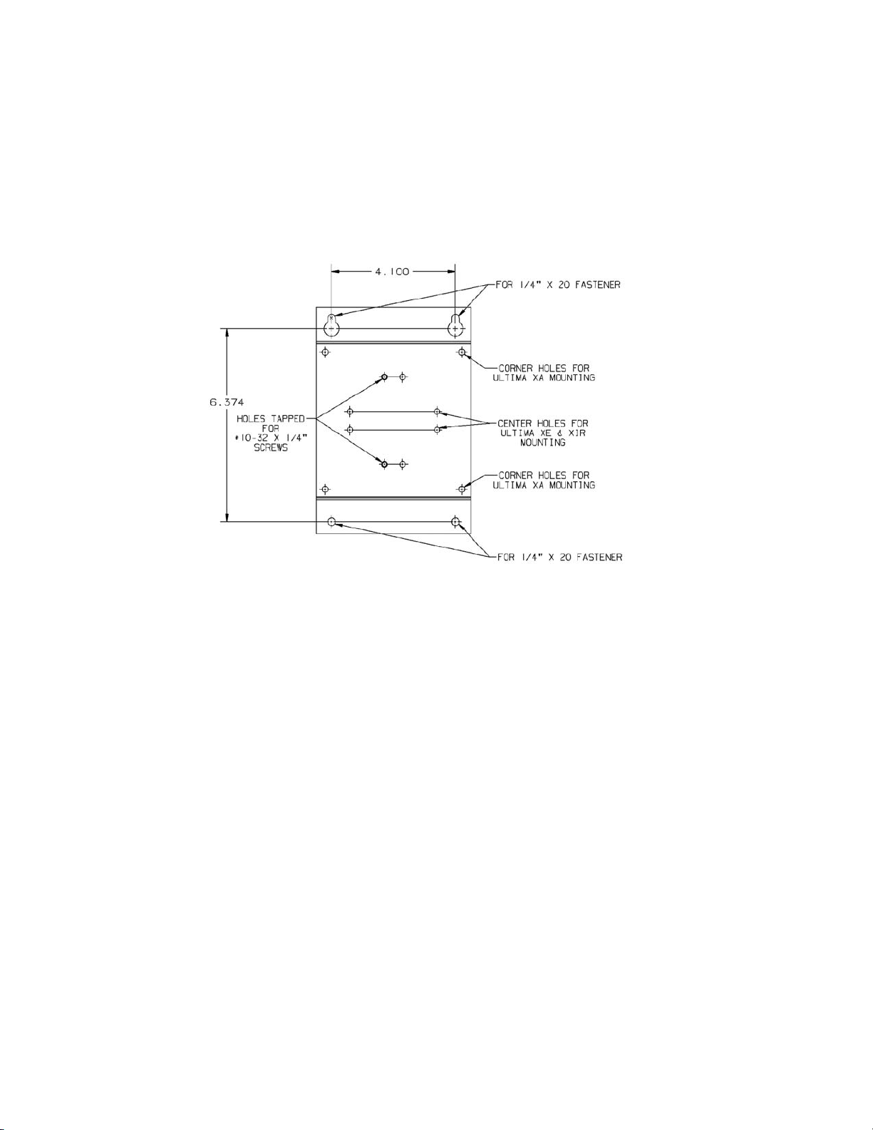
.
Figure 1-7. Ultima XE and XIR Mounting Bracket
1-7

Installing the Ultima XIR Gas Monitor
The Ultima XIR Gas Monitor contains no user- or field-serviceable parts and must be returned to the factory for repair.
Any attempt to open the monitor will damage the unit and
void the warranty.
Under no circumstances should a wrench or pry-bar be
applied to the two legs that support the unit's reflectors during installation or removal of the sensor (FIGURE 1-8).
Applying force to the legs can permanently damage the
monitor.
It is recommended that the monitor's environmental guard
be installed on the unit at all times. If the monitor is to be
operated without the guard, frequent checks should be
made to ensure particulate or liquid matter has not collected
on the windows.
• The optional Mounting Bracket (P/N 10047561) can be attached to
the rear holes of the Ultima XE Gas Monitor (FIGURE 1-7).
• The Ultima XIR Gas Sensor is factory-installed on the stainless
steel gas monitor. The Ultima XIR Monitor must be installed with
the XIR sensor in a horizontal position (see FIGURE 1-3) to
prevent the build-up of particulate or liquid matter on the monitor
optical surface.
• The Ultima XIR Gas Sensor is intended for use only on
metal enclosures.
.
Figure 1-8. Ultima XIR
"
CAUTION
"
WARNING
1-8
Electrical Connections
for Ultima X Gas Monitors
Before wiring the Ultima X Series Gas Monitors, disconnect
power source supplying the monitor; otherwise, electrical
shock or ignition of hazardous atmospheres could occur.
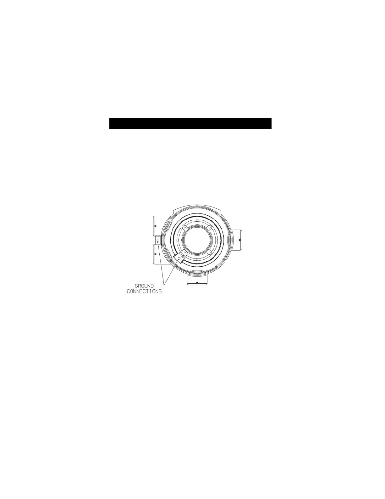
For Ultima XE and XIR installations, the internal grounding
terminal (located on the interior bottom of the Ultima XE
main enclosure) must be used for equipment grounding. The
external grounding terminal is only to be used as a supplemental bonding connection where local authorities permit or
require such a connection. See FIGURE 1-9 for location of
grounding terminals.
.
NOTE: For Ultima X Series units with internal relays, see Appendix A.
This assembly is marked to identify power, ground and signal
connections.
• A two-wire connection is possible for certain:
• Toxic Gas models
• Oxygen models
• A three-wire connection is required for all:
• Combustible Gas models
• Toxic and Oxygen models with internal relays.
Figure 1-9. Ultima XE Grounding Terminals
"
WARNING
1-9

Wiring for all Models
Install wiring in accordance with the electrical code of the country in use
and UL 61010-A1 or CSA C22.2 No. 1010.1, as applicable. In these
installations, twisted-pair, instrument quality cable is recommended.
Shielded cable is recommended for cable runs where interferences from
radio frequency interference (RFI), electromagnetic interference (EMI)
or other noise sources exist (such as motors, welding equipment,
heaters, etc.).
NOTE: See Installation Outline Drawings for wiring details as specified
in TABLE 1-1.
Table 1-1. Installation Outline Drawing List
MODEL TYPE DOCUMENT NO.
Ultima XA Gas Monitor SK3015-1027
Ultima XE Gas Monitor SK3015-1025
Ultima XIR Gas Monitor SK3015-1026
Conduit may also be needed in areas where large amounts of electrical
noise is expected.
Use caution when selecting a cable size. TABLE 1-2 expresses the
maximum cable length when only using the Ultima X Series Gas
Monitors. Ultima X Series options may take additional power which
requires a heavier cable or a short cable run. Cable distances for units
with internal relays are specified in Appendix A, TABLE A-1.
When selecting cable size, consider future needs (i.e., addition of
sensors and/or options available with the Ultima X Series Gas
Monitors). See Chapter 3, TABLE 3-1, "Performance Specifications"
for proper input voltage.
Ensure that water and dirt are not able to enter the unit via the wire or
conduit. If the unit is installed in a location known to be wet or damp, it
is good practice to loop or bend the entry into the unit that prevents
water incursion.
All cable shields should be terminated to earth ground at one end only.
1-10

Table 1-2. Cable Length and Wire Size
for Units Without Internal Relays
GAS SENSOR DC WIRE MAXIMUM MAXIMUM
TYPE OUTPUT VOLTAGE SIZE CABLE LENGTH LOAD
SUPPLY (AWG) WITHOUT HART RESISTANCE
(FEET) (METERS) (OHMS)
Oxygen
or Toxic 2 Wire 12 VDC 22 4000 1219 100
900(w/HART) 274 (w/HART) 50 (w/HART)
24 VDC 22 7,000 2134 500
Oxygen
or Toxic 3 Wire 24 VDC 22 10,000 3048 500
Combustible 3 Wire 12 VDC 18 900 274 250
16 1,400 427 250
12 3,600 1097 250
Combustible 3 Wire 24 VDC 18 2,500 762 500
16 4,200 1280 500
12 10,000 3048 500
XIR 3 wire 12 VDC 18 300 91 250
16 500 152 250
12 900 274 250
XIR 3 wire 24 VDC 18 2,000 610 500
16 3,500 1067 500
12 5,000 1524 500
An external power supply is required to supply 8-30 VDC to the Ultima X
Series Gas Monitor (For power requirements, see Chapter 3,
"Specifications"). All connections should be made by following appropriate
wire code procedures.
For proper installation of an AC power supply used with an Ultima X Series
transmitter, refer to the following drawings for detailed information. Optional
12 VDC or 24 VDC internal and external power supplies can be ordered
with the Ultima X Series Gas Monitors.
1-11

Table 1-3. Installation Outline Drawings
for Ultima X Power Supplies
MODEL POWER POWER SUPPLY POWER INSTALLATION OUTLINE
SUPPLY OUTPUT VOLTAGE SPECIFICATION DRAWING NUMBER
XA External 12 VDC 1.25 Amps, 15 W 10000020129
External 24 VDC 0.46 Amps, 11 W 10000020127
Internal 12 or 24 VDC see above SK3015-1027
XE External 12 VDC 1.25 Amps, 15 W 10000020130
External 24 VDC 0.46 Amps, 11 W 10000020128
Internal 12 or 24 VDC see above SK3015-1025 (XE) or
SK3015-1026 (XIR)
Use of External Controllers
The Ultima X Series Gas Monitors may be connected to any device
capable of accepting 4-20 mA analog signals, such as:
• Suprema Controller
• Model 9010/9020 Controller
• GasGard family controllers
• Quad Gas Controller
• Programmable Controllers
• DCS’s, etc.
When using any of the the Ultima X Series accessories (such
as relays) with the 4 to 20 mA output Ultima X Series Gas
Monitor, a three-wire connection must be used. Failure to
use a three-wire connection could damage the electronics
within the Ultima X Series Gas Monitor which can result in
serious personal injury or loss of life.
Be sure to install your Ultima X Series Gas Monitor according to National Electrical and local procedural codes. Failure
to do so can result in an unsafe condition.
"
WARNING
1-12

Identify PCB Configuration
• Identify the main pc board as a two-wire or a three-wire unit:
• For XA Gas Monitors:
while looking at the main pc board, locate the identifying label
on the underside of the lid:
• A-ULTX-PCB-A-1 is a two-wire unit, 4-20 mA output
• A-ULTX-PCB-A-2 is a two-wire unit with HART protocol on
the 4-20 mA output
• A-ULTX-PCB-A-3 is a three-wire unit, 4-20 mA output
• A-ULTX-PCB-A-4 is a three-wire unit with HART protocol
on the 4-20 mA output
• For XE and XIR Gas Monitors:
locate the identifying label on the side of the plastic shroud for
the main pc board:
• A-ULTX-PCB-E-1 is a two-wire unit, 4-20 mA output
• A-ULTX-PCB-E-2 is a two-wire unit with HART protocol on
the 4-20 mA output
• A-ULTX-PCB-E-3 is a three-wire unit, 4-20 mA output
• A-ULTX-PCB-E-4 is a three-wire unit with HART protocol
on the 4-20 mA output.
1-13
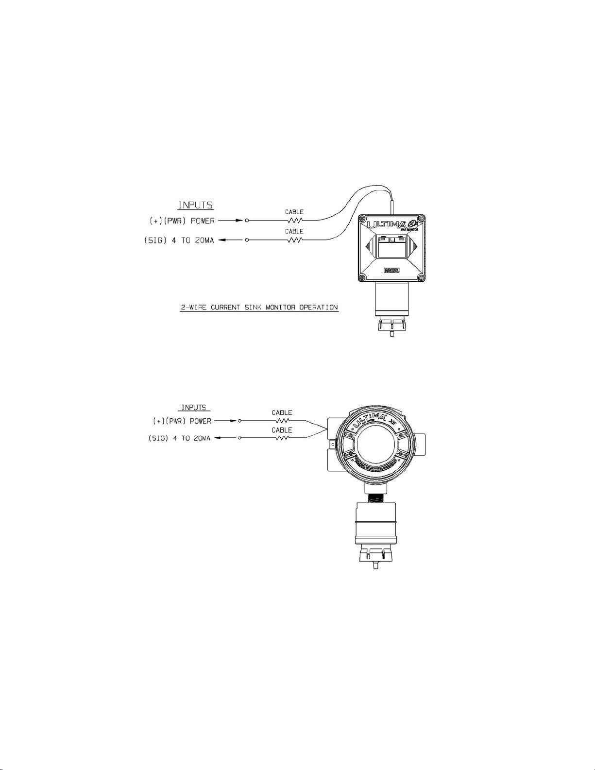
• Two-wire 4 to 20 mA Ultima X Series Monitors operate in the
current loop mode (FIGURE 1-10 for general-purpose)
(FIGURE1-11 for explosion-proof).
.
.
Figure 1-11. Explosion-Proof Two-Wire Operation
Figure 1-10. General-Purpose Two-Wire Operation
1-14
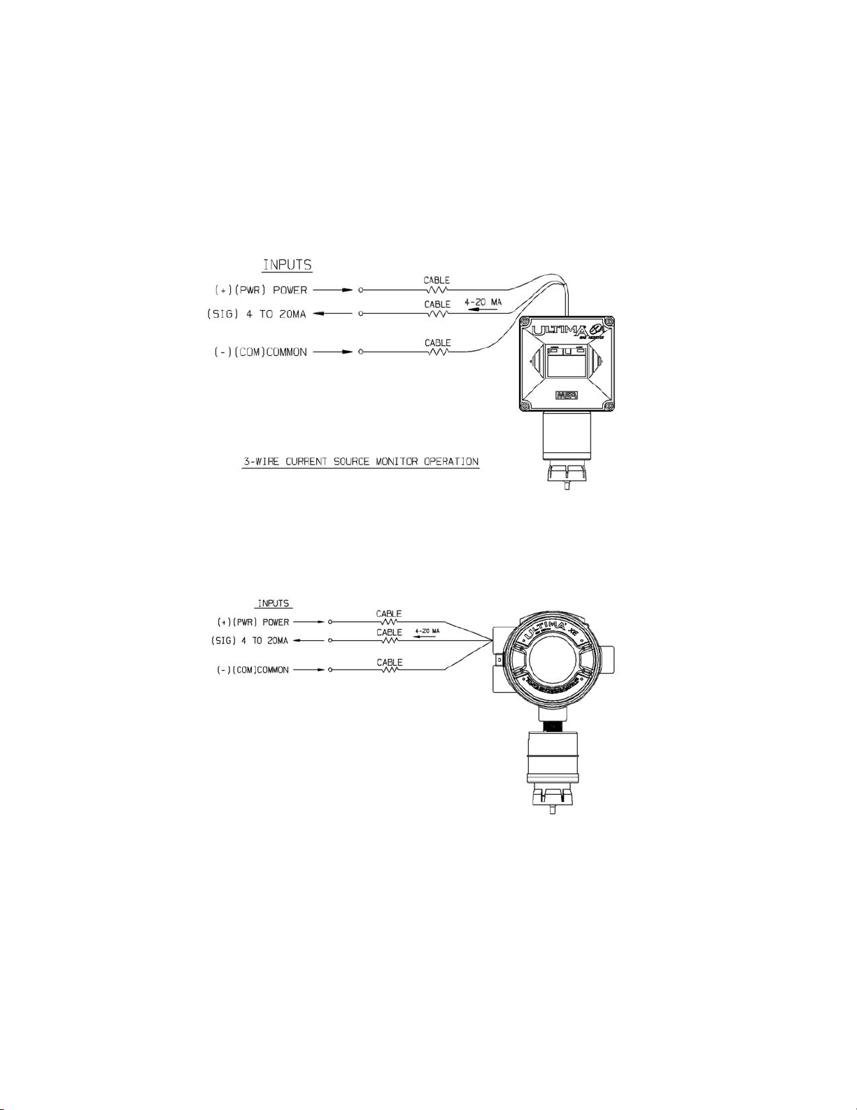
• Three-wire Ultima X Series Monitors operate in the current source
mode (see FIGURE 1-12 for general-purpose) (FIGURE 1-13 for
explosion-proof).
.
.
Figure 1-13. Explosion-Proof Three-Wire Operation
Figure 1-12. General-Purpose Three-Wire Operation
1-15
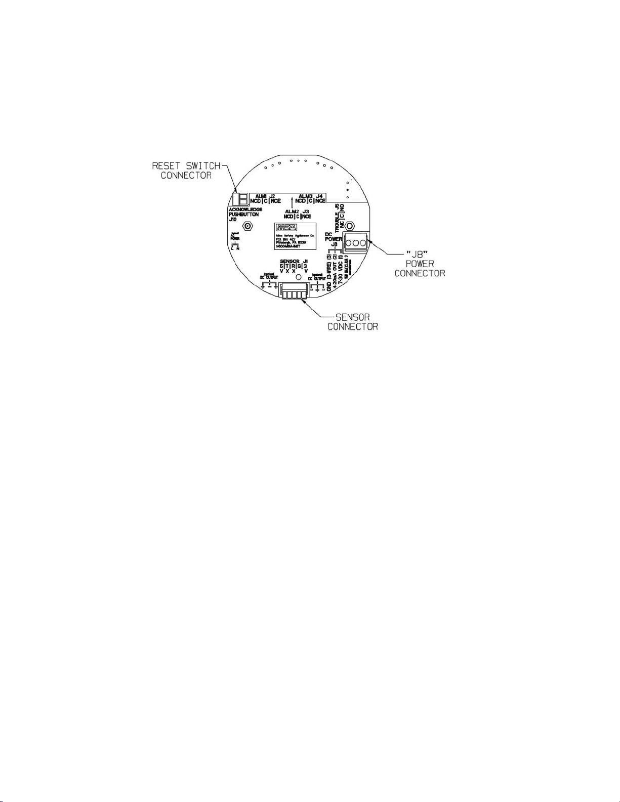
Installation of Two-Wire, 4-20 mA Output (no HART Protocol)
1. Connect 8-30 VDC power lead to J8-1 (see FIGURE 1-14)
2. Connect J8-2 to the 4-20 mA output on the remote system.
3. Connect the sensor module to main pc board connector J-1.
4. Assemble lid on the enclosure.
Figure 1-14. Two-Wire Printed Circuit Board
(no HART Protocol)
1-16
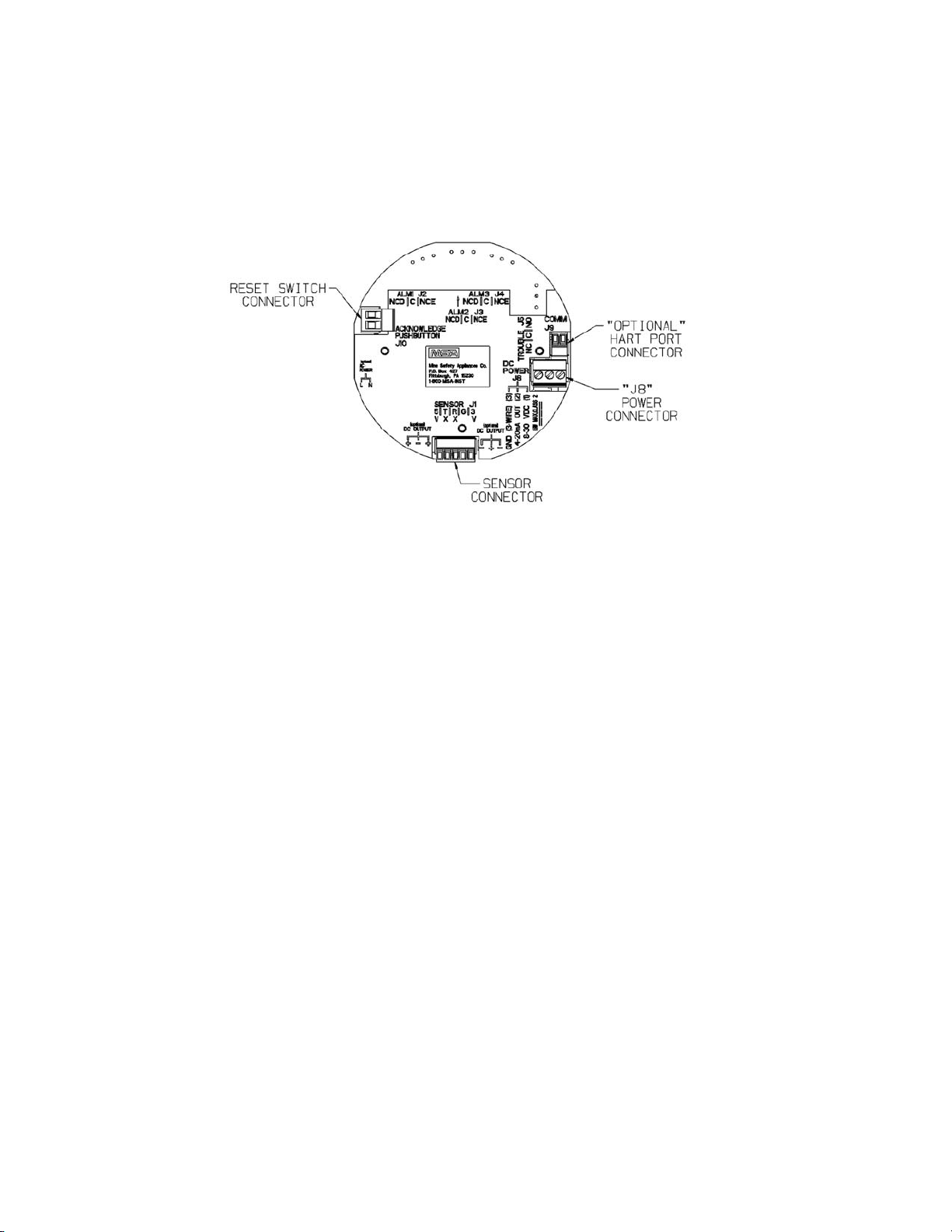
Installation of Two-Wire, 4-20 mA Output with HART Protocol
1. Connect 12-30 VDC power lead to J8-1 (see FIGURE 1-15).
NOTE: The HART signal is not available below 12 VDC
on the two-wire pc board.
2. Connect J8-2 to the 4-20 mA input on the remote system.
3. Terminate the 4-20 mA line with 230-500 Ohms of resistance.
4. Connect sensor module to main pc board connector J-1.
5. Assemble lid on the enclosure.
Figure 1-15. Two-Wire Printed Circuit Board
(with HART Protocol)
1-17
 Loading...