

Page 1
Installation & Maintenance Instructions
Ultima® X Series Gas Monitors
Registered Address
ABLE Instruments & Controls Ltd
Cutbush Park, Danehill, Lower Earley,
Reading, Berk shire, RG6 4UT. UK.
Reading
Tel: +44 (0)118 9311188 | Email: info@able.co.uk
Aberdeen
Tel: +44 (0)1224 725999 | Email: ab@able.co.uk
Web
able.co.uk
E-commerce
247abl e.com
Page 2
Ultima®X Series
Gas Monitors
Instruction Manual
In North America, to contact your nearest stocking location, dial toll-free 1-800-MSA-INST.
To contact MSA International, dial (724) 776-8626.
Inquiries can also be e-mailed to customer.service@msaSafety.com.
© MSA 2014 - All Rights Reserved
This manual is available on the internet at www.msaSafety.com
Manufactured by
MSA NORTH AMERICA
1000 Cranberry Woods Drive, Cranberry Township, PA 16066
(L) -Y Rev 9 10036101
Page 3

THIS MANUAL MUST BE CAREFULLY READ BY ALL INDIVIDUALS WHO HAVE OR WILL
HAVE THE RESPONSIBILITY FOR USING OR SERVICING THE PRODUCT. Like any piece
of complex equipment, this instrument will perform as designed only if it is used and serviced in accordance with the manufacturer’s instructions. OTHERWISE, IT COULD FAIL TO
PERFORM AS DESIGNED AND PERSONS WHO RELY ON THIS PRODUCT FOR THEIR
SAFETY COULD SUSTAIN SEVERE PERSONAL INJURY OR LOSS OF LIFE.
The warranties made by Mine Safety Appliances Company with respect to the product are
voided if the product is not used and serviced in accordance with the instructions in this
manual. Please protect yourself and others by following them. We encourage our customers to write or call regarding this equipment prior to use or for any additional information relative to use or service.
MSA Instrument Warranty
1. Warranty- Seller warrants that this product will be free from
mechanical defect or faulty workmanship for the following periods:
• Gas Monitor: eighteen (18) months from date of shipment or
one (1) year from installation, whichever occurs first
• Oxygen, Toxic or Catalytic Combustible Sensor: eighteen (18)
months from date of shipment or one (1) year from installation,
whichever occurs first
• IR Sensor source: ten (10) years from date of shipment.
All other IR components: two (2) years from date of shipment.
This warranty is applicable provided the product is maintained and
used in accordance with Seller's instructions and/or
recommendations. This warranty does not apply to expendable or
consumable parts whose normal life expectancy is less than one
(1) year. The Seller shall be released from all obligations under this
warranty in the event repairs or modifications are made by persons
other than its own or authorized service personnel or if the
warranty claim results from physical abuse or misuse of the
product. No agent, employee or representative of the Seller has
any authority to bind the Seller to any affirmation, representation or
warranty concerning the goods sold under this contract. Seller
makes no warranty concerning components or accessories not
manufactured by the Seller, but will pass on to the Purchaser all
warranties of manufacturers of such components. THIS
WARRANTY IS IN LIEU OF ALL OTHER WARRANTIES,
EXPRESSED, IMPLIED OR STATUTORY, AND IS STRICTLY
LIMITED TO THE TERMS HEREOF. SELLER SPECIFICALLY
DISCLAIMS ANY WARRANTY OF MERCHANTABILITY OR OF
FITNESS FOR A PARTICULAR PURPOSE.
"! WARNING
Page 4

NOTE: This equipment has been tested and found to comply with
the limits for a Class A digital device, pursuant to part 15 of
the FCC Rules. These limits are designed to provide reasonable protection against harmful interference when the
equipment is operated in a commercial environment. This
equipment generates, uses, and can radiate radio frequency energy and, if not installed and used in accordance with
the instruction manual, may cause harmful interference to
radio communications. Operation of this equipment in a
residential area is likely to cause harmful interference, in
which case the user will be required to correct the interference at his own expense.
This is a class A product in accordance with CISPR 22. In a
domestic environment, this product may cause radio interference, in which case the user may be required to take adequate measures.
2. Exclusive Remedy- It is expressly agreed that Purchaser's sole
and exclusive remedy for breach of the above warranty, for any
tortious conduct of Seller, or for any other cause of action, shall be
the repair and/or replacement at Seller's option, of any equipment
or parts thereof, which after examination by Seller is proven to be
defective. Replacement equipment and/or parts will be provided at
no cost to Purchaser, F.O.B. Seller's Plant. Failure of Seller to
successfully repair any nonconforming product shall not cause the
remedy established hereby to fail of its essential purpose.
3. Exclusion of Consequential Damage- Purchaser specifically
understands and agrees that under no circumstances will seller be
liable to purchaser for economic, special, incidental or
consequential damages or losses of any kind whatsoever, including
but not limited to, loss of anticipated profits and any other loss
caused by reason of nonoperation of the goods. This exclusion is
applicable to claims for breach of warranty, tortious conduct or any
other cause of action against seller.
"
WARNING
i
Page 5

General Warnings and Cautions
1. The Ultima X Series Gas Monitors described in this manual must
be installed, operated and maintained in strict accordance with
their labels, cautions, warnings, instructions, and within limitations
stated. Verify that the class, group, and temperature ratings of the
equipment agree with the actual classification of the location.
2. The Ultima X Series Gas Monitor is designed to detect gases or
vapors in air. It cannot measure the concentration of gases or
vapors in steam or inert or oxygen-deficient atmospheres. The
oxygen sensor can measure oxygen-deficient atmospheres.
3. Electrochemical sensors are sealed units which contain a corrosive
electrolyte. Should a sensor develop leakage, it must be
immediately removed from service; then, remove it from the
sensing head and discard it properly. Caution must be exercised so
that the electrolyte does not contact skin, eyes, clothing or circuitry;
otherwise, serious personal injury (burns) and/or equipment
damage may result.
4. Use only genuine MSA replacement parts when performing any
maintenance procedures provided in this manual. Failure to do so
may seriously impair instrument performance. Repair or alteration
of the Ultima X Series Gas Monitor, beyond the scope of these
maintenance instructions or by anyone other than an authorized
MSA service personnel, could cause the product to fail to perform
as designed and persons who rely on this product for their safety
could sustain serious personal injury or loss of life.
5. Do not locate the general-purpose enclosure models in an area
which may contain a flammable mixture of gas and air; otherwise,
an explosion may occur. The general-purpose Ultima X Series Gas
Monitors can be a source of ignition and must not be mounted in
an area where a flammable mixture of combustible gas and air
may become present; otherwise, an explosion may occur. If such a
location must be monitored, use an explosion-proof Ultima X
Series Gas Monitor model.
6. The Ultima XIR Infrared combustible gas monitor detects the
presence of most combustible gases by identifying the difference in
the amount of infrared light energy absorbed during the presence
of these gases. This monitor, however, does NOT detect the
presence of hydrogen gas and must never be used to monitor for
hydrogen gas.
7. The standard Ultima XIR Infrared Combustible Gas Monitor does
"
WARNING
ii
Page 6

not detect the presence of acetylene gas and the presence of
acetylene gas will degrade sensor performance. Custom-built
acetylene sensors are available through your MSA representative.
8. Gas detectors depend on an unimpeded gas flow for proper
operation. In environments where contamination is possible,
ensure that the flow remains unobstructed at the sensor. Failure to
follow this may prevent gas detection and generate inaccurate
readings.
9. CSA performance Certification to standard C22.2 No. 152 is valid
only when the instrument is calibrated on methane per the
instruction manual.
10. Install Product in accordance with all markings and the regulations
of the country in use.
11. Product components may have different hazardous location
ratings. Ensure all components are suitable for the area of
installation and protection technique.
Failure to follow the above can result in serious personal injury or loss of life.
1. As with all gas monitors of these types, high levels of, or long
exposure to, certain compounds in the tested atmosphere could
contaminate the sensors. In atmospheres where an Ultima X
Series Gas Monitor may be exposed to such materials, calibration
must be performed frequently to ensure that operation is
dependable and display indications are accurate.
2. The Ultima X Series Gas Monitor must not be painted. If painting is
done in an area where a Monitor is located, care must be
exercised to ensure that paint is not deposited on the sintered,
metal flashback arrestor in the inlet fitting of the Ultima X Series
Gas Monitor, if so equipped. Such paint deposits would interfere
with the diffusion process, whereby a sample of the atmosphere
being monitored diffuses into the Monitor.
3. The only absolute method to ensure proper overall operation of an
Ultima X Series Monitor is to check it with a known concentration
of the gas for which it has been calibrated. Consequently,
calibration checks must be included as part of the routine
inspection of the system.
4. Protect the Ultima X Series Gas Monitor from extreme vibration.
Do not mount the sensing head in direct sunlight as this may cause
overheating of the sensor.
Failure to follow the above can result in injury, product damage and/or an unsafe
condition.
"
CAUTION
iii
Page 7

Table of Contents
Chapter 1,
Installation . . . . . . . . . . . . . . . . . . . . . . . . . . . . . .1-1
General Description . . . . . . . . . . . . . . . . . . . . . . . . . . . . . . . . .1-1
Identifying Your Unit . . . . . . . . . . . . . . . . . . . . . . . . . . . . . . . .1-1
Installing Your Gas Monitor . . . . . . . . . . . . . . . . . . . . . . . . . . .1-5
Installing the Ultima XA Gas Monitor . . . . . . . . . . . . . .1-6
Installing the Ultima XE Gas Monitor . . . . . . . . . . . . . .1-6
Installing the Ultima XIR Gas Monitor . . . . . . . . . . . . .1-8
Electrical Connections for Ultima X Gas Monitors . . . . . . . . .1-9
Wiring for all Models . . . . . . . . . . . . . . . . . . . . . . . . .1-10
Use of External Controllers . . . . . . . . . . . . . . . . . . . . . . . . . .1-12
Identify PCB Configuration . . . . . . . . . . . . . . . . . . . . . . . . . .1-13
Installing the Ultima X Remote Sensor Module . . . . . . . . . .1-20
Electrical Connections for Remote Sensors . . . . . . . . . . . . .1-21
Chapter 2,
Start-up and Calibration . . . . . . . . . . . . . . . . . . .2-1
Initial Start-up . . . . . . . . . . . . . . . . . . . . . . . . . . . . . . . . . . . . . .2-1
Calibration Basics . . . . . . . . . . . . . . . . . . . . . . . . . . . . . . . . . .2-4
Ultima Calibrator . . . . . . . . . . . . . . . . . . . . . . . . . . . . .2-6
Ultima Controller . . . . . . . . . . . . . . . . . . . . . . . . . . . . .2-6
Calibration Output Signal . . . . . . . . . . . . . . . . . . . . . . .2-6
Calibration Kit . . . . . . . . . . . . . . . . . . . . . . . . . . . . . . .2-7
Ultima X Series Gas Monitor Calibration Procedure . . . . . . . .2-7
Equipment Required . . . . . . . . . . . . . . . . . . . . . . . . . .2-8
Span Gas Values . . . . . . . . . . . . . . . . . . . . . . . . . . . . .2-9
INITIAL Calibration . . . . . . . . . . . . . . . . . . . . . . . . . . .2-12
Standard Calibration . . . . . . . . . . . . . . . . . . . . . . . . .2-13
OXYGEN Calibration . . . . . . . . . . . . . . . . . . . . . . . . .2-18
XIR Calibration . . . . . . . . . . . . . . . . . . . . . . . . . . . . . .2-18
iv
Page 8

Chapter 3,
Specifications . . . . . . . . . . . . . . . . . . . . . . . . . . . .3-1
Chapter 4, Maintenance . . . . . . . . . . . . . . . . . . . .4-1
General . . . . . . . . . . . . . . . . . . . . . . . . . . . . . . . . . . . . . . .4-1
Ultima XIR Cleaning Procedure . . . . . . . . . . . . . . . . . . . . . . .4-4
Replacing an Ultima XE or Ultima XA Sensor . . . . . . . . . . . .4-5
Obtaining Replacement Parts . . . . . . . . . . . . . . . . . . . . . . . . .4-8
Appendix A,
Optional Features . . . . . . . . . . . . . . . . . . . . . . . .A-1
1) Internal Relays . . . . . . . . . . . . . . . . . . . . . . . . . . . . . . . . . .A-1
General Information . . . . . . . . . . . . . . . . . . . . . . . . . . .A-1
Unpacking, Mounting and Wiring . . . . . . . . . . . . . . . .A-1
Ultima X Series Gas Monitor Internal Relays . . . . . . .A-2
Relay Specifications . . . . . . . . . . . . . . . . . . . . . . . . . .A-2
Alarm Relays . . . . . . . . . . . . . . . . . . . . . . . . . . . . . . . .A-3
Fault Relay or Trouble . . . . . . . . . . . . . . . . . . . . . . . . .A-4
Relay Connections . . . . . . . . . . . . . . . . . . . . . . . . . . .A-5
2) Optional RESET Push-button . . . . . . . . . . . . . . . . . . . . . . .A-7
General . . . . . . . . . . . . . . . . . . . . . . . . . . . . . . . . . . . .A-7
RESET Button Selection . . . . . . . . . . . . . . . . . . . . . . .A-7
Optional Push-button Calibration . . . . . . . . . . . . . . . .A-8
3) Optional Horn Relay Software . . . . . . . . . . . . . . . . . . . . . .A-9
To Activate the Horn Relay . . . . . . . . . . . . . . . . . . . . .A-9
To Reset the Horn Relay . . . . . . . . . . . . . . . . . . . . . . .A-9
Appendix B,
Calibration Guide for Additional XIR/XI Gases .B-1
Appendix C,
General Certification Information . . . . . . . . . . .C-1
v
Page 9

Appendix D,
HART Specific Information . . . . . . . . . . . . . . . . .D-1
HART Field Device Specification . . . . . . . . . . . . . . . . . . . . . .D-1
Host Interface . . . . . . . . . . . . . . . . . . . . . . . . . . . . . . .D-2
Status Information . . . . . . . . . . . . . . . . . . . . . . . . . . . .D-3
Extended Device Status . . . . . . . . . . . . . . . . . . . . . . .D-3
Universal Commands . . . . . . . . . . . . . . . . . . . . . . . . .D-5
Common-Practice Commands . . . . . . . . . . . . . . . . . .D-5
Burst Mode . . . . . . . . . . . . . . . . . . . . . . . . . . . . . . . . .D-6
Catch Device Variable . . . . . . . . . . . . . . . . . . . . . . . . .D-6
Command #129: Read Sensor Gas Type . . . . . . . . . .D-7
Command #130: Read Device Real Time Clock . . . .D-7
Command #131: Read Alarm Setpoints . . . . . . . . . . .D-8
Command #132: Read Alarm Control Actions . . . . . .D-9
Command #133: Read Min, Max, Avg Values . . . . . .D-9
Command #134: Read Last Cal Date . . . . . . . . . . . .D-10
Command #135: Read Gas Table . . . . . . . . . . . . . . .D-10
Command #136: Read Input Voltage Value . . . . . . .D-10
Command #137: Read Auto Zero Comp Value . . . .D-11
Command #139: Read Sensor Status message . . . .D-11
Command #140: Read Swap Delay Status . . . . . . .D-11
Command #141: Read Cal Signal Status . . . . . . . . .D-12
Command #142: Read Alert Option Status . . . . . . . .D-12
Command #143: Read Sensor Temperature . . . . . .D-13
Command #144: Read Relay Normal State . . . . . . .D-13
Command #173: Write RTC . . . . . . . . . . . . . . . . . . .D-14
Command #174: Write Alarm Setpoints . . . . . . . . . .D-15
Command #175: Write Alarm Setpoint
Control Actions . . . . . . . . . . . . . . . . . . . . . . . . . . . . .D-16
Command #176: Write Average Interval . . . . . . . . . .D-17
Command #177: Write Upper Trim Point . . . . . . . . .D-18
Command #178: Write Gas Table . . . . . . . . . . . . . . .D-19
Command #179: Write Sensor Data Sheet
Reset Control . . . . . . . . . . . . . . . . . . . . . . . . . . . . . .D-20
Command #180: Write Sensor Swap Delay Enable .D-21
Command #181: Write Cal Signal Enable . . . . . . . .D-22
Command #182: Write Calibration Mode . . . . . . . . .D-23
Command #183: Write Calibration Abort . . . . . . . . .D-24
Command #184: Write Calibration Step . . . . . . . . . .D-25
vi
Page 10

Command #185: Write Alarm Acknowledge . . . . . . .D-26
Command #186: Write Protect Mode . . . . . . . . . . . .D-27
Command #187: Write Alert Option . . . . . . . . . . . . .D-28
Command #188: Write Relay Normal State . . . . . . .D-29
Performance . . . . . . . . . . . . . . . . . . . . . . . . . . . . . . .D-32
Power-Up . . . . . . . . . . . . . . . . . . . . . . . . . . . . . . . . .D-32
Reset . . . . . . . . . . . . . . . . . . . . . . . . . . . . . . . . . . . . .D-32
Self-Test . . . . . . . . . . . . . . . . . . . . . . . . . . . . . . . . . .D-32
Busy and Delayed-Response . . . . . . . . . . . . . . . . . .D-33
Long Messages . . . . . . . . . . . . . . . . . . . . . . . . . . . . .D-33
Non-Volatile Memory . . . . . . . . . . . . . . . . . . . . . . . . .D-33
Modes . . . . . . . . . . . . . . . . . . . . . . . . . . . . . . . . . . . .D-34
Write Protection . . . . . . . . . . . . . . . . . . . . . . . . . . . . .D-34
Damping . . . . . . . . . . . . . . . . . . . . . . . . . . . . . . . . . .D-34
Capability Checklist . . . . . . . . . . . . . . . . . . . . . . . . . . . . . . . .D-34
Default Configuration . . . . . . . . . . . . . . . . . . . . . . . . . . . . . .D-35
Calibration Using a HART® Communicator . . . . . . . . . . . . .D-35
Sensor Zero Selection Menu . . . . . . . . . . . . . . . . . .D-35
Standard Zero/Span Calibration Selection Menu . . .D-37
Initial Calibration Procedures . . . . . . . . . . . . . . . . . .D-40
User Calibration Selection Menu . . . . . . . . . . . . . . .D-40
Troubleshooting . . . . . . . . . . . . . . . . . . . . . . . . . . . . . . . . . .D-54
Span Fault . . . . . . . . . . . . . . . . . . . . . . . . . . . . . . . . .D-54
Zero Fault . . . . . . . . . . . . . . . . . . . . . . . . . . . . . . . . .D-57
vii
Page 11

List of Figures
Figure 1-1. General-Purpose Ultima XA Monitor . . . . . . . . . .1-1
Figure 1-2. -Proof Ultima XE Monitor . . . . . . . . . . . . . . . . . . .1-2
Figure 1-3. Explosion-Proof Ultima XIR Monitor . . . . . . . . . . .1-2
Figure 1-4. General-Purpose XA Remote Sensor Module . . .1-3
Figure 1-5. Explosion-Proof XE Remote Sensor Module . . . .1-3
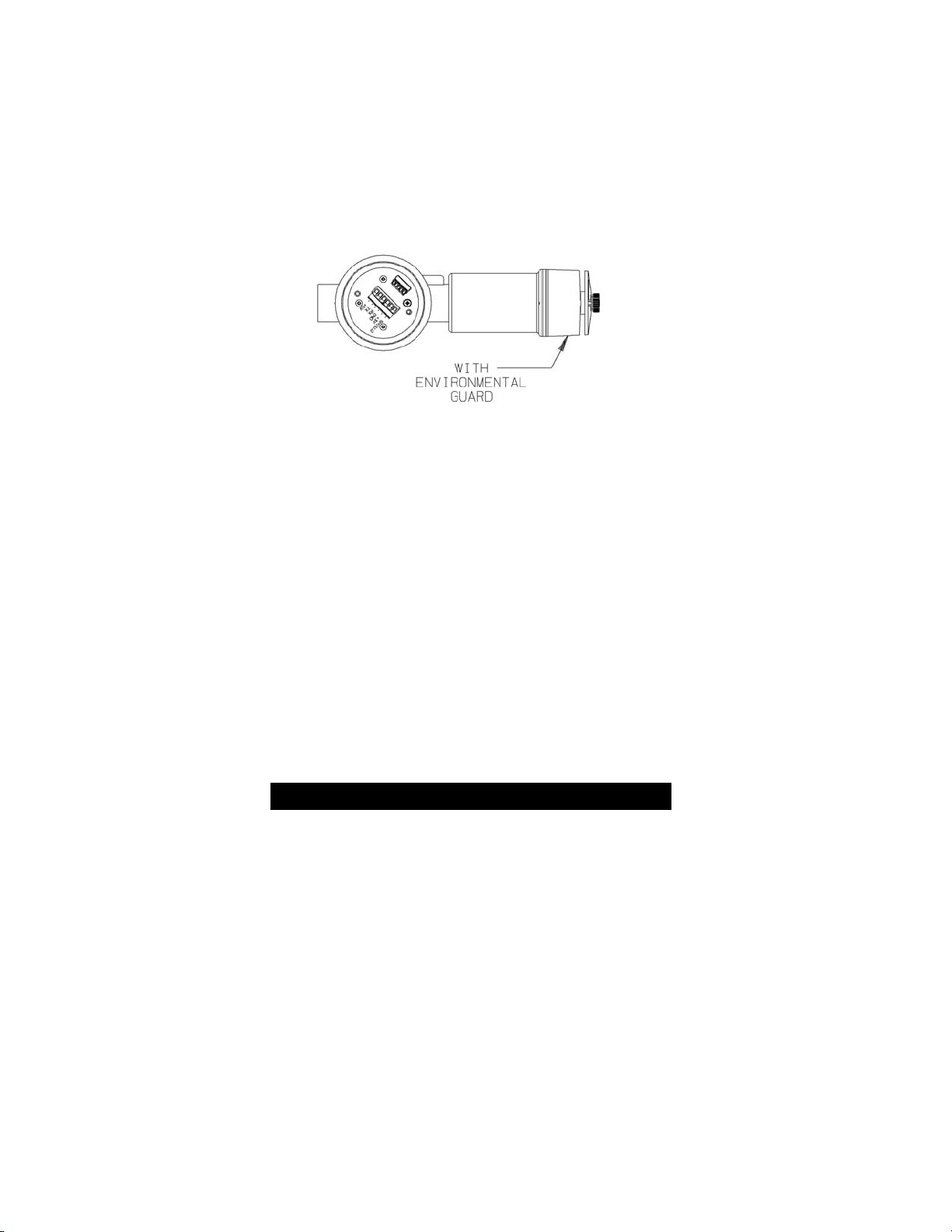
Figure 1-6. Explosion-Proof XIR Remote Sensor Module . . .1-4
Figure 1-7. Ultima XE and XIR Mounting Bracket . . . . . . . . .1-7
Figure 1-8. Ultima XIR . . . . . . . . . . . . . . . . . . . . . . . . . . . . . . .1-8
Figure 1-9. Ultima XE Grounding Terminals . . . . . . . . . . . . . .1-9
Figure 1-10. General-Purpose Two-Wire Operation . . . . . . .1-14
Figure 1-11. Explosion-Proof Two-Wire Operation . . . . . . . .1-14
Figure 1-12. General-Purpose Three-Wire Operation . . . . . .1-15
Figure 1-13. Explosion-Proof Three-Wire Operation . . . . . . .1-15
Figure 1-14. Two-Wire Printed Circuit Board
(no HART Protocol) . . . . . . . . . . . . . . . . . . . . . .1-16
Figure 1-15. Two-Wire Printed Circuit Board
(with HART Protocol) . . . . . . . . . . . . . . . . . . . . .1-17
Figure 1-16. Three-Wire Printed Circuit Board
(no HART Protocol) . . . . . . . . . . . . . . . . . . . . . .1-18
Figure 1-17. Three-Wire Printed Circuit Board
(with HART Protocol) . . . . . . . . . . . . . . . . . . . . .1-19
Figure 1-18. Remote Module General-Purpose
Ultima X Series Wiring . . . . . . . . . . . . . . . . . . . .1-20
Figure 1-19. Remote Module Explosion-Proof
Ultima X Series Wiring . . . . . . . . . . . . . . . . . . . .1-20
Figure 2-1. LCD Gas Concentration Display . . . . . . . . . . . . . .2-1
Figure 2-2. Ultima Calibrator . . . . . . . . . . . . . . . . . . . . . . . . . .2-5
Figure 2-3. Ultima Controller . . . . . . . . . . . . . . . . . . . . . . . . . .2-5
Figure 2-4. Ultima X Optional Push-button Calibrator . . . . . . .2-5
Figure 2-5. Apply ZERO Gas Flag . . . . . . . . . . . . . . . . . . . .2-14
Figure 2-6. Apply SPAN Gas Flag . . . . . . . . . . . . . . . . . . . . .2-15
Figure 2-7. Calibration End Display . . . . . . . . . . . . . . . . . . .2-17
Figure 4-1. "Change Sensor" Scrolls Across the Display . . . .4-6
Figure 4-2. Sensor Assembly and Sensor Guard
for General-Purpose Model . . . . . . . . . . . . . . . . .4-7
Figure A-1. Relay Contacts . . . . . . . . . . . . . . . . . . . . . . . . . . .A-4
Figure A-2. Relay Printed Circuit Board . . . . . . . . . . . . . . . . .A-6
Figure D-1. Zero cal step screen . . . . . . . . . . . . . . . . . . . . .D-41
viii
Page 12

Figure D-2. Span cal step screen . . . . . . . . . . . . . . . . . . . . .D-41
Figure D-3. Select Sensor Calibration
from the Sensor Trim Menu . . . . . . . . . . . . . . . .D-42
Figure D-4. First Warning screen . . . . . . . . . . . . . . . . . . . . .D-43
Figure D-5. Second Warning screen . . . . . . . . . . . . . . . . . .D-44
Figure D-6. Standard Calibration function select screen . . .D-45
Figure D-7. Calibration initiated screen . . . . . . . . . . . . . . . .D-46
Figure D-8. Selection Confirmation screen . . . . . . . . . . . . . .D-47
Figure D-9. Sensor Zero Countdown screen . . . . . . . . . . . .D-48
Figure D-10. Zero Adjustment screen . . . . . . . . . . . . . . . . . .D-49
Figure D-11. Span Countdown screen . . . . . . . . . . . . . . . . .D-50
Figure D-12. Adjusting Span screen . . . . . . . . . . . . . . . . . . .D-51
Figure D-13. Calibration Completion message . . . . . . . . . . .D-52
Figure D-14. Calibration Gas Reminder screen . . . . . . . . . .D-53
Figure D-15. Loop Control Reminder message . . . . . . . . . .D-54
Figure D-16. Calibration Status screen . . . . . . . . . . . . . . . . .D-55
Figure D-17. Sensor Trim Point screen . . . . . . . . . . . . . . . .D-56
Figure D-18. Additional Sensor Status screen . . . . . . . . . . .D-57
Figure D-19. Device Status screen . . . . . . . . . . . . . . . . . . . .D-58
ix
Page 13

List of Tables
Table 1-1. Installation Outline Drawing List . . . . . . . . . . . . . .1-10
Table 1-2. Cable Length and Wire Size for Units without
Internal Relays . . . . . . . . . . . . . . . . . . . . . . . . . .1-11
Table 1-3. Installation Outline Drawings
for Ultima X Power Supplies . . . . . . . . . . . . . . .1-12
Table 1-4. Remote Module Wiring and Placement . . . . . . . .1-22
Table 1-5. Remote Sensor Wiring Cable . . . . . . . . . . . . . . . .1-22
Table 1-6. Low Temperature Wiring Cable . . . . . . . . . . . . . .1-22
Table 2-1. Instrument Operation . . . . . . . . . . . . . . . . . . . . . . .2-2
Table 2-2. Factory-set Span Values . . . . . . . . . . . . . . . . . . . .2-9
Table 2-3. Calibration Guide for Combustible Gas Sensor . .2-11
Table 3-1. Performance Specifications . . . . . . . . . . . . . . . . . .3-1
Table 3-2. Sensor Response to Interferants . . . . . . . . . . . . . .3-4
Table 4-1. Operational Display Messages . . . . . . . . . . . . . . . .4-1
Table 4-2. Configuration Display Messages . . . . . . . . . . . . . .4-2
Table 4-3. Troubleshooting Guidelines . . . . . . . . . . . . . . . . . .4-2
Table 4-4. Replacement Parts . . . . . . . . . . . . . . . . . . . . . . . . .4-8
Table A-1. Power Cable Distances for the Ultima X
Series Gas Monitor with Internal Relays . . . . . .A-2
Table A-2. Relay Specifications . . . . . . . . . . . . . . . . . . . . . . . .A-2
Table A-3. Push-button Calibration . . . . . . . . . . . . . . . . . . . . .A-8
Table D-1. Device Identification . . . . . . . . . . . . . . . . . . . . . . .D-1
Table D-2. Current Values . . . . . . . . . . . . . . . . . . . . . . . . . . . .D-2
Table D-3. Device Variables Exposed by the Ultima Monitor .D-3
Table D-4. Dynamic Variable implemented by Ultima Monitor D-3
Table D-5. Additional Device Status (Command #48) . . . . . .D-4
Table D-6. Supported Commands . . . . . . . . . . . . . . . . . . . . .D-6
Table D-7. Device-Specific Commands . . . . . . . . . . . . . . . . .D-7
Table D-8. Gas Type Descriptions . . . . . . . . . . . . . . . . . . . .D-30
Table D-9. Alarm Control Actions . . . . . . . . . . . . . . . . . . . . .D-30
Table D-10. Gas Table Values . . . . . . . . . . . . . . . . . . . . . . .D-30
Table D-11. Calibration Modes . . . . . . . . . . . . . . . . . . . . . . .D-31
Table D-12. Sensor Status Codes . . . . . . . . . . . . . . . . . . . .D-31
Table D-13. Sampling Rates . . . . . . . . . . . . . . . . . . . . . . . . .D-32
Table D-14. Command Response Times . . . . . . . . . . . . . . .D-33
Table D-15. Capability Checklist . . . . . . . . . . . . . . . . . . . . . .D-34
Table D-16. Default Configuration . . . . . . . . . . . . . . . . . . . .D-35
x
Page 14
1-1
Chapter 1,
Installation
General Description
The Ultima X Series Gas Monitor is designed to sample the
environment where mounted and alert you to potentially dangerous
levels of your target gas, depending on your particular model. The
Ultima X Series device uses various detection methods, depending on
the gas of interest. Detection methods can be electrochemical, infrared,
pellement or other technologies. The Ultima XE Gas Monitor is an
explosion-proof device suitable for installation in hazardous locations.
The Ultima XA Gas Monitor is a general-purpose version in a plastic
enclosure for use in nonexplosive atmospheres only. The Ultima X Gas
Monitor can be ordered with the standard 4 to 20 mA analog output or
with an optional HART (Highway Addressable Remote Transducer)
protocol, which is superimposed on the 4 to 20 mA signal. The unit is
factory-calibrated and shipped ready for installation.
The main sensor input is provided via a five-terminal interface that
provides a digital interface for 3 VDC or 5 VDC sensor modules. Many
different sensor modules are available, providing sensing capability for a
large variety of gases. The operating range varies with the type of cell
(e.g., electrochemical, pellistor or infrared combustible, etc.).
Identifying Your Unit
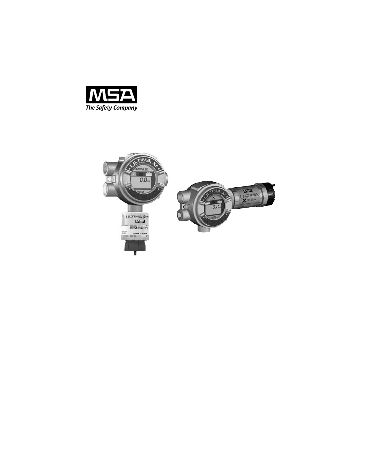
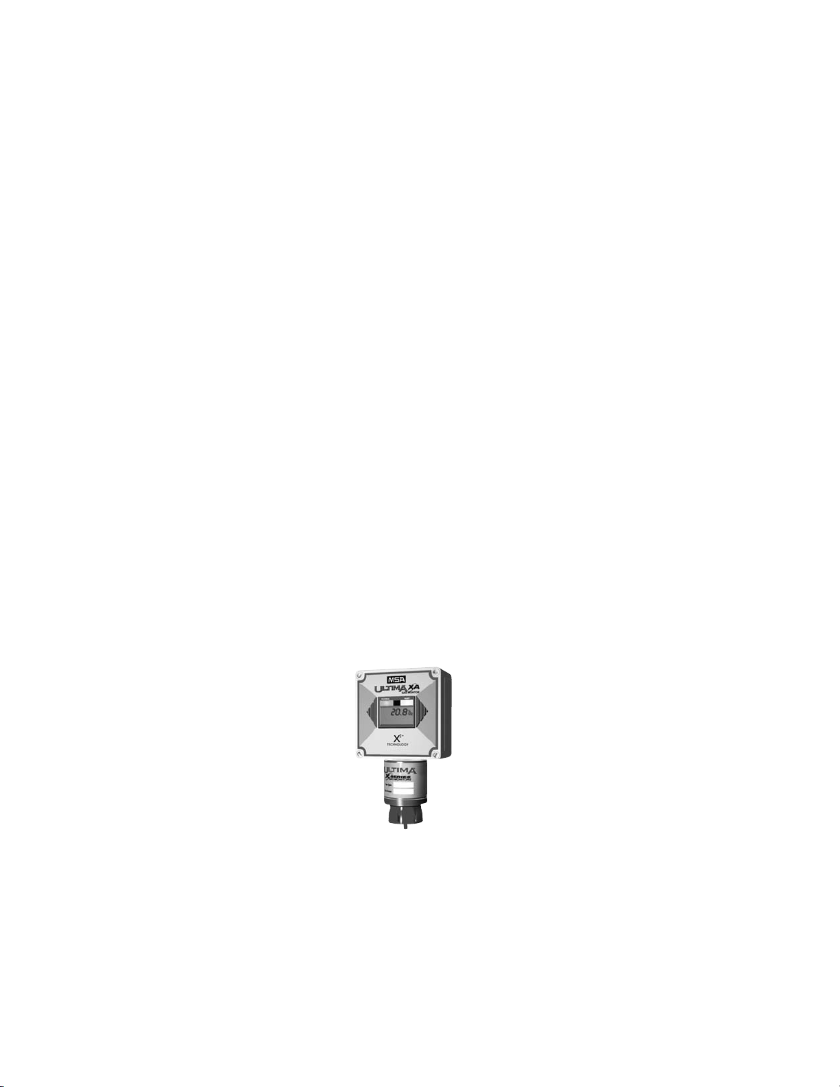
The Ultima XA Gas Monitor is housed in a rugged, plastic generalpurpose enclosure (FIGURE 1-1).
Figure 1-1. General-Purpose Ultima XA Monitor
Page 15
The Ultima XE Gas Monitor is housed in a 316 stainless steel
explosion-proof enclosure (FIGURE 1-2 shows the Ultima XE
with the optional explosion-proof HART port).
.
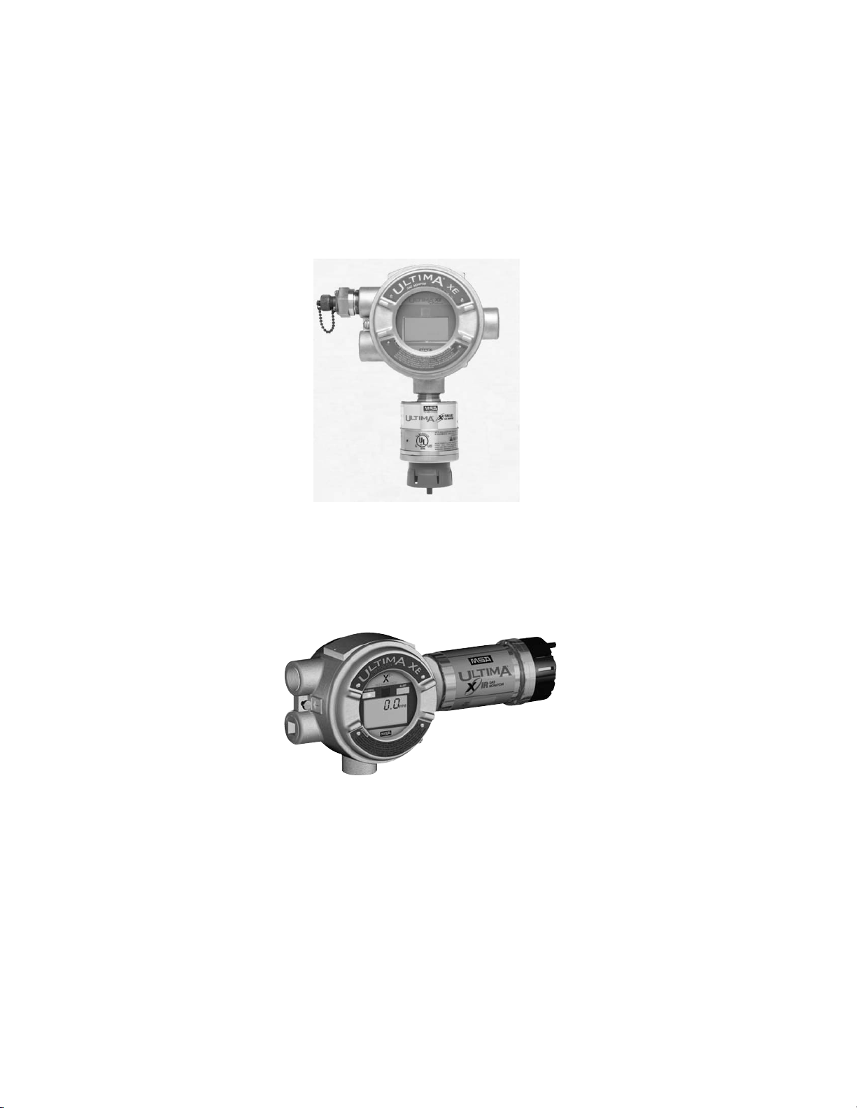
The Ultima XIR Gas Monitor is housed in a 316 stainless steel
explosion-proof enclosure (FIGURE 1-3).
If your application requires the sensor head to be located separately
from the control unit, all models are available with Remote Sensor
Modules (shown in FIGURES 1-4, 1-5 and 1-6).
Figure 1-3. Explosion-Proof Ultima XIR Monitor
Figure 1-2. Explosion-Proof Ultima XE Monitor
1-2
Page 16
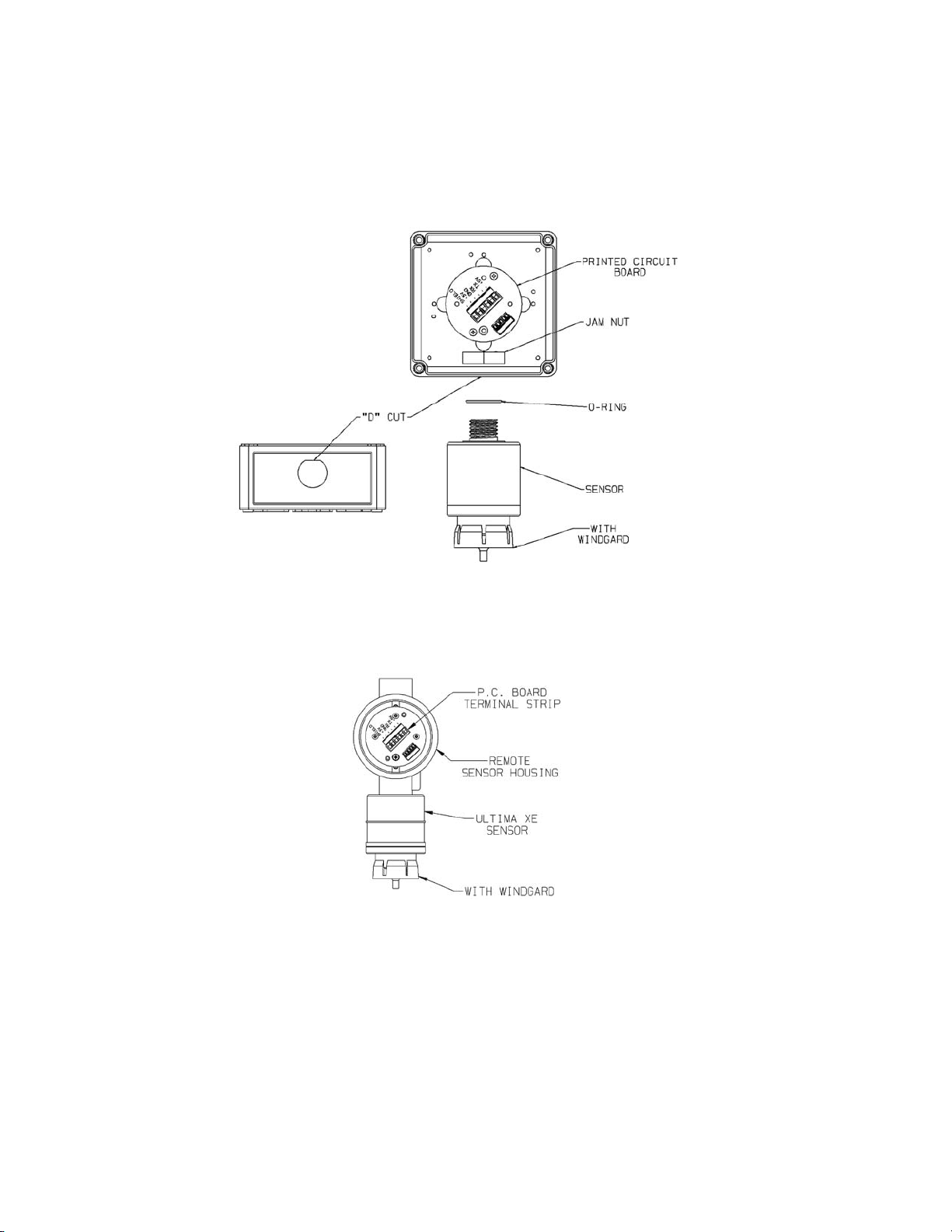
Figure 1-5. Explosion-Proof XE Remote Sensor Module
Figure 1-4. General-Purpose XA Remote Sensor Module
1-3
Page 17
To determine your sensor type and options, check the shipping carton.
Checked items are included in the carton. The carton label identifies:
• Type of unit supplied (Gas Monitor, Gas Monitor Less Sensor, or
Remote Sensor Module)
• Type of gas (combustible gas, toxic gas or oxygen)
• Range [% LEL, PPM (parts per million), or %]
• Output (2- or 3-wire, 4 to 20 mA, or 4 to 20 mA with HART)
• Any options such as internal relays and/or LEDs.
• If your unit contains internal relays, see Appendix A.
Also check the sensor ID label located on the inside of the sensor. This
can be viewed by unscrewing the lower portion of the sensor. If
performing this while the unit is powered, see the following Warning.
The sensor ID label identifies the detectable gas and the gas range.
For Ultima XE sensors marked Class I, Groups A, B, C and D
and not used in Class II areas, unscrew sensor cap at least
three full turns (but no more than four full turns from its
tightly-closed position), wait 10 seconds, and then remove
cap completely. Failure to follow this warning can result in
the ignition of a hazardous atmosphere.
For the Ultima XE Sensor marked Class II Groups F and G,
atmosphere must be free of dust and the power removed
from the unit before the sensor cap can be removed from the
housing. Failure to follow this warning can result in the ignition of a hazardous atmosphere.
"
WARNING
Figure 1-6. Explosion-Proof XIR Remote Sensor Module
1-4
Page 18

Your Ultima XE Series Gas Monitor may also include a separate HART
Module if you ordered the following optional accessories:
1). Internal Power Supply and explosion-proof HART Port
2). External RESET Push-button and explosion-proof HART Port.
Installing Your Gas Monitor
NOTE: Reference installation outline drawings listed in TABLE 1-1.
Generally, the Ultima X Series Gas Monitors or remote sensing
module should be mounted close to the area where a leak is likely to
occur or where the gas is expected. Install the Ultima X Series Gas
Monitors or the remote sensing module at a high level (ceiling) or low
level (floor), depending on the density of the gas most likely to be
found. Install the unit so that the front display of the unit is not blocked
or hidden from view.
Mount the Ultima XE or XA Gas Monitor or remote sensing
module with the sensor inlet fitting (FIGURE 1-1, 1-2, 1-4 or
1-5) pointed downward; otherwise, the inlet may become
clogged with particulate matter or liquids.
Mount the Ultima XIR Gas Monitor or XIR Remote Sensing
Module with the sensor inlet fitting extended horizontally
from the main enclosure (FIGURE 1-3 and 1-6) to prevent the
build-up of particulate or liquid matter on the monitor's optical surfaces.
Do not paint the Ultima X Series Gas Monitors. If painting is
done in an area where a sensor is located, exercise CAUTION to ensure paint is not deposited on the sensor inlet fitting. Such paint deposits would interfere with the diffusion
process, whereby a sample of the monitored atmosphere
diffuses into the sensor. In addition, solvents in the paint
may cause an alarm condition to occur.
Protect the Ultima X Series Gas Monitors from extreme
vibration. Do not mount sensing head in direct sunlight as
this may cause overheating of the sensor.
"
CAUTION
1-5
Page 19

Do not locate the general-purpose enclosure models in an
area which may contain a flammable mixture of gas and air;
otherwise, an explosion may occur. The general-purpose
Ultima X Series Gas Monitors can be a source of ignition and
must not be mounted in an area where a flammable mixture
of combustible gas and air may become present; otherwise,
an explosion may occur. If such a location must be monitored, use an explosion-proof gas monitor.
Installing the Ultima XA Gas Monitor
Remove lid and drill enclosure for power, signal and optional relay cable
entry. Use one of the following methods to mount the general-purpose
Ultima XA Gas Monitor/Less Sensor or the Ultima XA Gas Monitor.
• Using customer-installed wiring holes, install the Ultima XA Gas
Monitor to the end of rigid conduit.
• Use mounting holes in the corners of the Ultima XA enclosure to
mount directly to a wall.
• Use mounting holes in the corners of the Ultima XA enclosure to
mount to the optional Mounting Kit (P/N 10047561);
see FIGURE 1-7.
• The Ultima XA gas sensor is not shipped attached to the main
enclosure. Ensure the sensor wiring harness is through the entry
and the sensor is pointed downward.
Installing the Ultima XE Gas Monitor
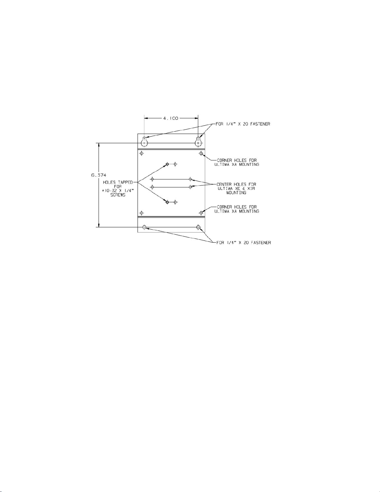
• The optional Mounting Bracket Kit (P/N 10047561) can be attached
to the rear holes of the Ultima XE Gas Monitor (FIGURE 1-7).
• The Ultima XE Gas Monitor main enclosure can be rotated 360°
and mounted to ensure easy access to any of the four entryways.
The electronics assembly inside the metal enclosure can be
repositioned in any of the four self-aligning interior holes to ensure
the display is properly oriented.
• The Ultima XE Gas Monitor sensor is not shipped attached to the
main enclosure. Ensure the sensor wiring harness is through the
entry and the sensor is pointing downward. Tighten with a strap
wrench.
"
WARNING
1-6
Page 20
.
Figure 1-7. Ultima XE and XIR Mounting Bracket
1-7
Page 21

Installing the Ultima XIR Gas Monitor
The Ultima XIR Gas Monitor contains no user- or field-serviceable parts and must be returned to the factory for repair.
Any attempt to open the monitor will damage the unit and
void the warranty.
Under no circumstances should a wrench or pry-bar be
applied to the two legs that support the unit's reflectors during installation or removal of the sensor (FIGURE 1-8).
Applying force to the legs can permanently damage the
monitor.
It is recommended that the monitor's environmental guard
be installed on the unit at all times. If the monitor is to be
operated without the guard, frequent checks should be
made to ensure particulate or liquid matter has not collected
on the windows.
• The optional Mounting Bracket (P/N 10047561) can be attached to
the rear holes of the Ultima XE Gas Monitor (FIGURE 1-7).
• The Ultima XIR Gas Sensor is factory-installed on the stainless
steel gas monitor. The Ultima XIR Monitor must be installed with
the XIR sensor in a horizontal position (see FIGURE 1-3) to
prevent the build-up of particulate or liquid matter on the monitor
optical surface.
• The Ultima XIR Gas Sensor is intended for use only on
metal enclosures.
.
Figure 1-8. Ultima XIR
"
CAUTION
"
WARNING
1-8
Page 22
Electrical Connections
for Ultima X Gas Monitors
Before wiring the Ultima X Series Gas Monitors, disconnect
power source supplying the monitor; otherwise, electrical
shock or ignition of hazardous atmospheres could occur.
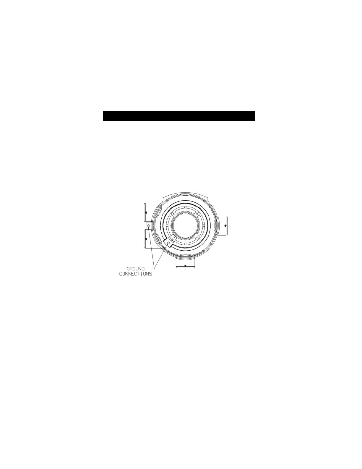
For Ultima XE and XIR installations, the internal grounding
terminal (located on the interior bottom of the Ultima XE
main enclosure) must be used for equipment grounding. The
external grounding terminal is only to be used as a supplemental bonding connection where local authorities permit or
require such a connection. See FIGURE 1-9 for location of
grounding terminals.
.
NOTE: For Ultima X Series units with internal relays, see Appendix A.
This assembly is marked to identify power, ground and signal
connections.
• A two-wire connection is possible for certain:
• Toxic Gas models
• Oxygen models
• A three-wire connection is required for all:
• Combustible Gas models
• Toxic and Oxygen models with internal relays.
Figure 1-9. Ultima XE Grounding Terminals
"
WARNING
1-9
Page 23

Wiring for all Models
Install wiring in accordance with the electrical code of the country in use
and UL 61010-A1 or CSA C22.2 No. 1010.1, as applicable. In these
installations, twisted-pair, instrument quality cable is recommended.
Shielded cable is recommended for cable runs where interferences from
radio frequency interference (RFI), electromagnetic interference (EMI)
or other noise sources exist (such as motors, welding equipment,
heaters, etc.).
NOTE: See Installation Outline Drawings for wiring details as specified
in TABLE 1-1.
Table 1-1. Installation Outline Drawing List
MODEL TYPE DOCUMENT NO.
Ultima XA Gas Monitor SK3015-1027
Ultima XE Gas Monitor SK3015-1025
Ultima XIR Gas Monitor SK3015-1026
Conduit may also be needed in areas where large amounts of electrical
noise is expected.
Use caution when selecting a cable size. TABLE 1-2 expresses the
maximum cable length when only using the Ultima X Series Gas
Monitors. Ultima X Series options may take additional power which
requires a heavier cable or a short cable run. Cable distances for units
with internal relays are specified in Appendix A, TABLE A-1.
When selecting cable size, consider future needs (i.e., addition of
sensors and/or options available with the Ultima X Series Gas
Monitors). See Chapter 3, TABLE 3-1, "Performance Specifications"
for proper input voltage.
Ensure that water and dirt are not able to enter the unit via the wire or
conduit. If the unit is installed in a location known to be wet or damp, it
is good practice to loop or bend the entry into the unit that prevents
water incursion.
All cable shields should be terminated to earth ground at one end only.
1-10
Page 24

Table 1-2. Cable Length and Wire Size
for Units Without Internal Relays
GAS SENSOR DC WIRE MAXIMUM MAXIMUM
TYPE OUTPUT VOLTAGE SIZE CABLE LENGTH LOAD
SUPPLY (AWG) WITHOUT HART RESISTANCE
(FEET) (METERS) (OHMS)
Oxygen
or Toxic 2 Wire 12 VDC 22 4000 1219 100
900(w/HART) 274 (w/HART) 50 (w/HART)
24 VDC 22 7,000 2134 500
Oxygen
or Toxic 3 Wire 24 VDC 22 10,000 3048 500
Combustible 3 Wire 12 VDC 18 900 274 250
16 1,400 427 250
12 3,600 1097 250
Combustible 3 Wire 24 VDC 18 2,500 762 500
16 4,200 1280 500
12 10,000 3048 500
XIR 3 wire 12 VDC 18 300 91 250
16 500 152 250
12 900 274 250
XIR 3 wire 24 VDC 18 2,000 610 500
16 3,500 1067 500
12 5,000 1524 500
An external power supply is required to supply 8-30 VDC to the Ultima X
Series Gas Monitor (For power requirements, see Chapter 3,
"Specifications"). All connections should be made by following appropriate
wire code procedures.
For proper installation of an AC power supply used with an Ultima X Series
transmitter, refer to the following drawings for detailed information. Optional
12 VDC or 24 VDC internal and external power supplies can be ordered
with the Ultima X Series Gas Monitors.
1-11
Page 25

Table 1-3. Installation Outline Drawings
for Ultima X Power Supplies
MODEL POWER POWER SUPPLY POWER INSTALLATION OUTLINE
SUPPLY OUTPUT VOLTAGE SPECIFICATION DRAWING NUMBER
XA External 12 VDC 1.25 Amps, 15 W 10000020129
External 24 VDC 0.46 Amps, 11 W 10000020127
Internal 12 or 24 VDC see above SK3015-1027
XE External 12 VDC 1.25 Amps, 15 W 10000020130
External 24 VDC 0.46 Amps, 11 W 10000020128
Internal 12 or 24 VDC see above SK3015-1025 (XE) or
SK3015-1026 (XIR)
Use of External Controllers
The Ultima X Series Gas Monitors may be connected to any device
capable of accepting 4-20 mA analog signals, such as:
• Suprema Controller
• Model 9010/9020 Controller
• GasGard family controllers
• Quad Gas Controller
• Programmable Controllers
• DCS’s, etc.
When using any of the the Ultima X Series accessories (such
as relays) with the 4 to 20 mA output Ultima X Series Gas
Monitor, a three-wire connection must be used. Failure to
use a three-wire connection could damage the electronics
within the Ultima X Series Gas Monitor which can result in
serious personal injury or loss of life.
Be sure to install your Ultima X Series Gas Monitor according to National Electrical and local procedural codes. Failure
to do so can result in an unsafe condition.
"
WARNING
1-12
Page 26

Identify PCB Configuration
• Identify the main pc board as a two-wire or a three-wire unit:
• For XA Gas Monitors:
while looking at the main pc board, locate the identifying label
on the underside of the lid:
• A-ULTX-PCB-A-1 is a two-wire unit, 4-20 mA output
• A-ULTX-PCB-A-2 is a two-wire unit with HART protocol on
the 4-20 mA output
• A-ULTX-PCB-A-3 is a three-wire unit, 4-20 mA output
• A-ULTX-PCB-A-4 is a three-wire unit with HART protocol
on the 4-20 mA output
• For XE and XIR Gas Monitors:
locate the identifying label on the side of the plastic shroud for
the main pc board:
• A-ULTX-PCB-E-1 is a two-wire unit, 4-20 mA output
• A-ULTX-PCB-E-2 is a two-wire unit with HART protocol on
the 4-20 mA output
• A-ULTX-PCB-E-3 is a three-wire unit, 4-20 mA output
• A-ULTX-PCB-E-4 is a three-wire unit with HART protocol
on the 4-20 mA output.
1-13
Page 27
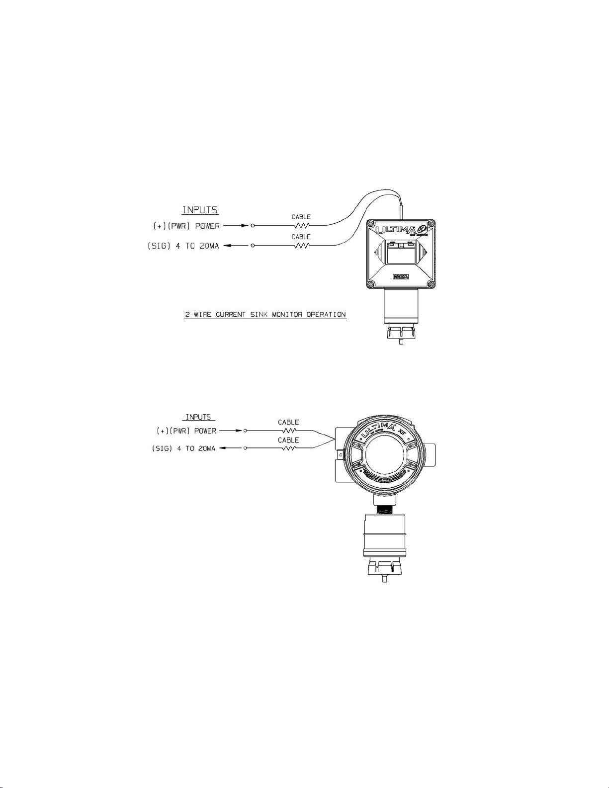
• Two-wire 4 to 20 mA Ultima X Series Monitors operate in the
current loop mode (FIGURE 1-10 for general-purpose)
(FIGURE1-11 for explosion-proof).
.
.
Figure 1-11. Explosion-Proof Two-Wire Operation
Figure 1-10. General-Purpose Two-Wire Operation
1-14
Page 28
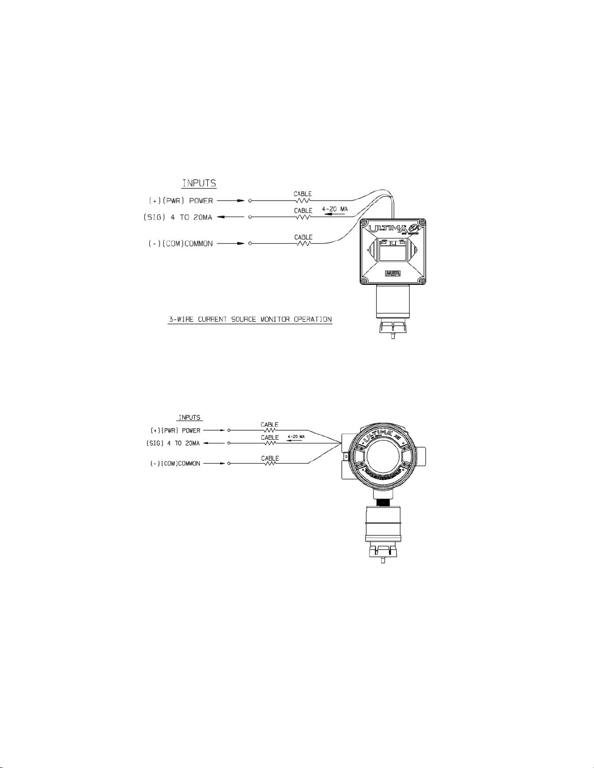
• Three-wire Ultima X Series Monitors operate in the current source
mode (see FIGURE 1-12 for general-purpose) (FIGURE 1-13 for
explosion-proof).
.
.
Figure 1-13. Explosion-Proof Three-Wire Operation
Figure 1-12. General-Purpose Three-Wire Operation
1-15
Page 29
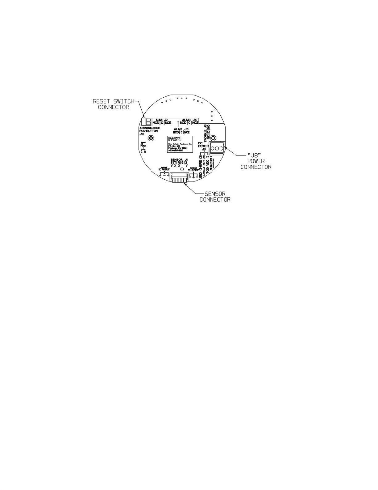
Installation of Two-Wire, 4-20 mA Output (no HART Protocol)
1. Connect 8-30 VDC power lead to J8-1 (see FIGURE 1-14)
2. Connect J8-2 to the 4-20 mA output on the remote system.
3. Connect the sensor module to main pc board connector J-1.
4. Assemble lid on the enclosure.
Figure 1-14. Two-Wire Printed Circuit Board
(no HART Protocol)
1-16
Page 30
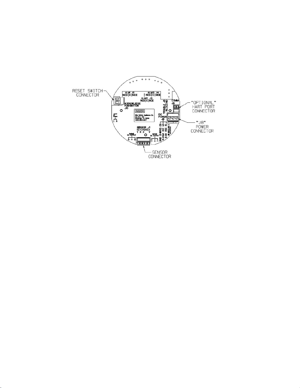
Installation of Two-Wire, 4-20 mA Output with HART Protocol
1. Connect 12-30 VDC power lead to J8-1 (see FIGURE 1-15).
NOTE: The HART signal is not available below 12 VDC
on the two-wire pc board.
2. Connect J8-2 to the 4-20 mA input on the remote system.
3. Terminate the 4-20 mA line with 230-500 Ohms of resistance.
4. Connect sensor module to main pc board connector J-1.
5. Assemble lid on the enclosure.
Figure 1-15. Two-Wire Printed Circuit Board
(with HART Protocol)
1-17
Page 31

Installation of Three-Wire, 4-20 mA Output (no HART Protocol)
1. Connect 8-30 VDC power lead to J8-1 (see FIGURE 1-16)
2. Connect J8-2 to the 4-20 mA output on the remote system.
3. For three-wire operation, connect the signal ground to J8-3.
4. Connect the sensor module to main pc board connector J-1.
5. Wire for optional relays, if applicable (see Appendix A).
6. Assemble lid on the enclosure.
Figure 1-16. Three-Wire Printed Circuit Board
(no HART Protocol)
1-18
Page 32

Installation of Three-Wire, 4-20 mA Output with HART Protocol
1. Connect 8-30 VDC power lead to J8-1 (see FIGURE 1-17)
2. Connect J8-2 to the 4-20 mA input on the remote system.
3. Terminate the 4-20 mA line with 230-500 Ohms of resistance.
4. For three-wire operation, connect the signal ground to J8-3.
5. Connect the sensor module to main pc board connector J-1.
6. Wire for optional relays, if applicable (see Appendix A).
7. Assemble lid on the enclosure.
Figure 1-17. Three-Wire Printed Circuit Board
(with HART Protocol)
1-19
Page 33

Installing the Ultima X Remote Sensor Module
The Remote Sensor Module is used with the Ultima X Gas Monitor for
installations requiring remote placement of the gas sensor.
FIGURES 1-18 and 1-19 show the general-purpose and explosion-proof
configurations.
Figure 1-19. Remote Module Explosion-Proof
Ultima X Series Wiring
Figure 1-18. Remote Module General-Purpose
Ultima X Series Wiring
1-20
Page 34

The Remote Sensor Module should be mounted in a manner similar to
the Ultima X (see Chapter 1, "Installing Your Gas Monitor") and at a
maximum distance outlined in TABLE 1-6.
Permanently connect 1/4" ID tubing to the post on the windguard. Route
this tubing to the Ultima X Gas Monitor, ensuring that there are no
kinks, leaks or other obstructions. Secure this tubing near the monitor; it
is used to deliver check gas to the sensor module during calibration.
Electrical Connections for Remote Sensors
Before wiring the Ultima X Series Remote Sensor Module,
disconnect the power source feeding the Remote Sensor
Module and the Ultima X Series Gas Monitor/Less Sensor;
otherwise, electrical shock or ignition of hazardous atmospheres could occur.
When installing an Ultima X Series Remote Sensor Module
with its mating Ultima X Series Gas Monitor/Less Sensor, follow National Electrical and local procedural Codes; failure to
do so can result in an unsafe condition.
Five conductors are required for the Ultima XE and Ultima XA Remote
Sensor Modules. Four conductors are required for the Ultima XIR
Remote Sensor Module. The Ultima X Series Monitor has a five-wire
terminal to accommodate up to #16 AWG conductors. For wiring details,
see the applicable Installation Outline Drawing listed in TABLE 1-1.
Some installations require metal pipe or metallic conduit. In these
cases, separate conductors or unshielded cable may be used.
For open wiring, shielded wire or cable should be used to minimize the
possibility of noise interference and contact with other voltages.
Selection of this shielded cable must comply with local requirements.
"
WARNING
"
WARNING
1-21
Page 35

Table 1-4. Remote Module Wiring and Placement
GAS TYPE MINIMUM WIRE SIZE MAXIMUM DISTANCE
Toxic and Oxygen 20 AWG 100 feet (30m)
Catalytic Combustible 18 AWG 50 feet (15 m)
16 AWG 100 feet (30 m)
*IR Combustible 16 AWG 50 feet (15 m)
12 AWG 100 fee (30 m)
TABLES 1-7 and 1-8 show suggested cables for Ultima X Series
installations; other cables are available which are also adequate.
Table 1-5. Remote Sensor Wiring Cable
SUPPLIER CATALOG NUMBER DESCRIPTION
Alpha Wire Corp 5525 5 cond., shielded, 18 AWG
5535 5 cond., shielded, 16 AWG
5514 4 cond., shielded, 20 AWG
Table 1-6. Low Temperature Wiring Cable
SUPPLIER CATALOG NUMBER DESCRIPTION
Alpha Wire Corp 45525 5 cond., shielded, 18 AWG
45366 6 cond., shielded, 16 AWG
45545 5 cond., shielded, 14 AWG
At the Ultima X Series Remote Sensor Location:
1. Open the Ultima X Series Remote Sensor cover by removing lid.
2. For the Ultima XA Gas Monitor, route the power and signal cable
from the Gas Monitor through a customer-created opening in the
enclosure and wire it to the appropriately labeled connection on the
terminal block (FIGURE 1-4).
For the Ultima XE or XIR Gas Monitor, route the cable from the
Gas Monitor through a wire entry hole in the enclosure and wire it
to the appropriately labeled connection on the terminal block
(FIGURE 1-5).
3. Verify the sensor connector is firmly seated on the terminal board.
4. Re-install the cover of the Ultima X Series Remote Sensor.
1-22
Page 36

NOTES:
Grounding
• Incoming power and signal cable shield should be earth grounded
at the power source.
• Connect power and remote sensor cable shields to shield terminals
on main pc board.
• Provide shield terminations inside the sensor housing as indicated
on Installation Outline Drawings for Remote Sensor. See
TABLE 1-1 for Installation Outline Drawing document numbers.
Cable Size
• Cables larger than #16 AWG will require a splice of smaller cable
to fit the connector.
1-23
Page 37

2-1
Chapter 2,
Start-up and Calibration
Initial Start-up
• The Ultima X Series Gas Monitors are factory-calibrated and ready
for immediate use.
• Once power is applied to the unit, the LCD shows a test of all
display words. The software version number displays; then, a 30second (self-check) countdown for sensor stability begins.
• During the 30-second countdown, the output signal is the same as
the calibration signal when enabled during a normal calibration.
This is described later in this chapter under "Ultima X Series Gas
Monitor Calibration Output Signal".
• For units with LEDs, the Alert red LED will be solid ON during the
30-second countdown.
• After the 30-second countdown, observe that the gas type and gas
concentration (ppm, % Gas, or % LEL) alternately flash
(FIGURE 2-1).
• For units with LEDs, the Normal green LED will be solid ON after
the 30-second countdown.
• A complete listing of instrument operation features can be found in
TABLE 2-1.
During normal operation, the Ultima X Monitor displays the gas
concentration of the surrounding environment. The corresponding
output signal can be transmitted to a controller or read directly from the
optional HART port with an HCF-approved communicator (such as the
Emerson 375 HART Communicator, or equivalent).
.
Figure 2-1. LCD Gas Concentration Display
Page 38

2-2
NOTE: The catalytic combustible model of the Ultima X Series Gas
Monitors is capable of detecting concentrations of certain combustible gases above 100% LEL. When exposed to these concentrations, the Ultima X Series Gas Monitors will display one
of two modes:
• +LOC % LEL - The Ultima X Series Gas Monitor has been
exposed to a high concentration of gas (above the LEL) and it
is possible that the over-range condition may still exist.
• OVER % LEL - The Ultima X Series Gas Monitor has been
exposed to a high concentration of gas (above the LEL) and
the over-range condition definitely still exists.
In either mode, correct the condition causing the excessive
gas level and vent or purge the area before attempting the
following.
In the +LOC % LEL mode, the output signal will also be
locked at full-scale. If this condition occurs, the Ultima X
Series Gas Monitor must be unlocked by performing a
"Zero Function" with the Ultima X Series Gas Monitor
Calibrator or Controller. The Ultima X Series Gas Monitor
will not revert to a normal condition until a successful zero
operation has been performed. This is an exclusive safety
feature of the Ultima X Series Gas Monitor which pre-empts
the possibility of ambiguous readings when the sensor is
exposed to concentration of gas above 100% LEL
In the OVER % LEL mode, the combustible gas is over
the100%LEL range. It returns to normal operation when
gas concentration level falls below 100%LEL.
Table 2-1. Instrument Operation
NOTES:
1
ALERT option causes the 4-20 mA output to be set to 3.75 mA during O2sensor
calibration (if the Cal Signal Option is also enabled). If the ALERT option is disabled and
the Cal Signal enabled, the output is set to 21 mA during the O2sensor calibration.
2
Swap Delay timeout is 60 seconds if enabled; 0 seconds otherwise.
3
The Swap Delay feature enables a one-minute hold-off of the Sensor Missing Fault,
allowing the user to "Swap" or change sensors without having the 4-20 mA set to a
fault condition.
4
Alarming operation are followed if the alarms are enabled.
"
CAUTION
Page 39

2-3
OPERATION LEDs 4 to 20 mA FAULT RELAY
GREEN RED
NORMAL ON OFF Gas value Energized
steady
ALARMING OFF Flashing Gas value Energized
FAULT OFF ON 3.0 mA De-energized
steady
POWER OFF ON <3.75 mA De-energized
UP (HART steady
Version)
POWER OFF ON <3.1 mA De-energized
UP steady
(Non-HART
Version)
COUNT OFF ON steady ALERT option1disabled; Energized
DOWN (All 21.0 mA for O2; if ALERT option disabled
Versions) 3.75 mA for others
ALERT option1enabled: De-energized
3.75 mA for all if ALERT option enabled
3
SENSOR OFF ON steady 3.0 mA if Swap Delay De-energized if Swap Delay
MISSING/ timeout2expired, timeout2expired, Swap
COUNT- Swap Delay3disabled Delay3 disabled or FAULT
DOWN or FAULT
Previous gas value Energized if Swap Delay
3
if Swap Delay3enabled enabled and Swap Delay
and Swap Delay timeout2timeout2not expired
not expired
SENSOR OFF ON steady 3.75 mA if cal signal Energized if ALERT
CAL enabled and ALERT option disabled
option1enabled;
gas value if cal signal
disabled
21.0 mA for O2if De-energized if ALERT
cal signal enabled and option enabled
1
ALERT option1disabled
CAL OFF ON steady 4 mA if 4 mA calibration Energized if ALERT option
4-20 selected disabled
20 mA if 20 mA De-energized if ALERT
calibration selected option enabled
1
CAL FAULT OFF ON steady Gas value De-energized two seconds
every minute
UNDER- OFF ON steady 3.0 mA if gas value De-energized
RANGE 0 or less;
gas value otherwise
OVER- ON OFF
4
21.0 mA Energized
RANGE/ steady
4
LOC
Page 40

2-4
Calibration Basics
While the Ultima X Series Gas Monitor is factory-calibrated, it is
good practice to calibrate the unit once it is installed in its final
environmental destination.
As with any type of gas monitor, the only true check of its performance
is to apply gas directly to the sensor. The frequency of the calibration
gas tests depends on the operating time and chemical exposures of
the sensors. New sensors should be calibrated more often until the
calibration records prove sensor stability. The calibration frequency
can then be reduced to the schedule set by the safety officer or
plant manager.
Catalytic Combustible sensors located in areas where non-combustible
chemicals may leak, particularly ones known to reduce the sensitivity
(see following list) should be calibrated after such exposures.
• Silanes, Silicates, Silicones and Halides (compounds containing
Fluorine, Chlorine, Iodine or Bromine)
• TABLE 3-2 in Chapter 3 lists interferants for
electrochemical sensors.
Before calibrating, the Ultima X Series Gas Monitor must be
powered for a minimum of one hour to allow the sensor to settle into its
new environment.
Before attempting a calibration, power the unit at least one
full hour.
To ensure a fully functional sensor, perform a calibration
check and adjustments at initial start-up and at regular
intervals.
When it is determined that calibration adjustments are required, the
Ultima X Series Gas Monitor provides a one-man, non-intrusive method
of adjustment at the unit.
To calibrate the unit, one of the following accessories is necessary:
• Ultima Calibrator P/N 809997 (FIGURE 2-2)
• Ultima Controller P/N 809086(FIGURE 2-3)
• Optional Push-button Calibration (FIGURE 2-4). Instructions for
use of the optional push-button are given in Appendix A.
"
CAUTION
Page 41

2-5
• HART®-compatible communications interface with Device
Description Language capability (DDL) or generic HART interface
with Manufacturer Specific Command capability. This hand-held
HART Communicator must be HART revision 7 compliant and can
be obtained from a HART-authorized supplier. See Appendix D for
command definitions.
.
.
.
Figure 2-4. Ultima X Optional Push-button Calibrator
Figure 2-3. Ultima Controller
Figure 2-2. Ultima Calibrator
Page 42

Ultima Calibrator
The Ultima Calibrator allows the following functions:
• Zero
• Calibration (zero and span)
• Changing address for some models.
Ultima Controller
The Ultima Controller also provides the above functions, plus access to
the following features:
• Three levels of alarm and relays
• Date of last successful calibration
• Maximum gas readings over selected time periods
• Average gas readings over selected time periods
• Changing span gas value from factory-set value
• Access to real-time clock for time and date
• Changing of full scale value.
NOTE: See Ultima Controller/Calibrator manual (P/N 813379) for
full functionality.
NOTE: When an Ultima X Series Gas Monitor has an active latched
alarm (indicated by a flashing alarm display):
• An infrared (IR) remote device (such as the Ultima
Calibrator or Controller) may be used to reset this alarm.
• The next IR command it receives from a calibration device
will reset the latched alarm (if it is not beyond the alarm
threshold). The intended IR command will be ignored and
interpreted as an 'alarm reset.' When the latching alarm
function is inactive, other valid IR commands may be used.
Calibration Output Signal
The Ultima X Series Gas Monitor is shipped with the calibration output
signal DISABLED so the output signal will track the gas concentration
value during the calibration process. In some applications, it may be
desirable to disable or lock the output to a pre-determined output value
to prevent activation of alarm devices. The calibration signal can be
ENABLED using the Ultima Controller or a HART controller with DDLor manufacturer-specific command capability. When the calibration
2-6
Page 43

2-7
signal is enabled, the output signal is 3.75 milliamps for the 4 to 20
milliamp output models.
NOTE: For oxygen sensors, the calibration signal will be 21 mA.
Oxygen can be set to a 3.75 mA calibration signal by turning
ON the ALERT option as described in the Ultima Controller
manual.
Calibration Kit
Calibration Kits are available for the Ultima X Gas Monitors. For the
recommended calibration kit, see Ultima Controller/Calibrator manual
(P/N 813379).
Ultima X Series Gas Monitor
Calibration Procedure
Read all calibration instructions before attempting an actual calibration.
Also, identify and become familiar with all of the calibration components.
During the calibration, it is necessary to quickly apply the span gas to
the unit. Prior connection of the calibration components will aid in the
ease of unit calibration.
The only true check of any gas monitor's performance is to apply gas
directly to the sensor. The calibration procedure must be performed
regularly.
NOTES:
• If this is the first calibration or, if the sensor element has been
changed or replaced, see Chapter 2, "Initial Calibration."
• If this is an oxygen sensor, see subsequent section, "Oxygen
Calibration."
• If this is an XIR sensor, see subsequent section, "XIR Calibration."
• Apply power to the unit at least 1 hour before calibrating.
• Due to the unstable nature of Chlorine Dioxide (ClO2), Chlorine
gas is used as a calibration simulant. If using the MSA calibration
system and gas cylinder (P/N 710331), the response ratio is 2:1. In
other words, the 2 ppm sample of Chlorine should be set to read 1
ppm of ClO2. The default value for the calibration gas on the ClO
2
Ultima X Series Gas Monitor is 1 ppm.
• For Cl2and ClO2calibration, do not mix regulators. Use only one
regulator for each of these gases. They will not work properly if
one regulator is used for multiple gases.
Page 44

2-8
• Due to the reactivity of HCL with flow system components, the flow
control regulator must only be used for HCL gas. HCL gas must be
run through the flow control regulator and tubing for five minutes
before attempting a calibration. After a successful calibration, flush
the flow control regulator and tubing with 100% Nitrogen for five
minutes. Store the flow control regulator in the desiccated bag
included in Calibration Kit 54 or equivalent dry container.
Equipment Required
Three calibration kits (numbered 40, 41, and 54) are available from
MSA for diffusion Ultima X Series Gas Monitors. Kit 40, 41, and 54 are
housed in a convenient carrying case and contain all items necessary
(less gas) for a complete and accurate calibration.
These Kits do not calibrate Ultima X Series units equipped with a flow
cap.
NOTE: The calibration procedure for the sample draw Ultima XE/XA
Monitor is the same as the procedure for the diffusion version,
except calibration gas is applied to the calibration entry port of
the inlet flow block and the cal kit for pumped units provides a
flow matching regulator.
The check or calibration gases can also be carried in the case. See
TABLE 2-2 for the appropriate zero and span gas cylinders for your
Ultima X Series Gas Monitor.
TABLE 2-2 shows the recommended calibration kit for Ultima X Series
Gas Monitors. Typically, Cal Kit 41 uses 0.25 LPM regulator and a
calibration cap to contain the calibration gas. Cal Kits 40 and 54 use a
1.5 LPM regulator and no calibration cap. If Cal Kit 41 is recommended
and the application is such that the calibration cap cannot be used
(such as for a remote sensor application), Cal Kit 40 may be used.
However, any time Cal Kit 40 is used, ambient wind conditions must be
minimized to avoid a calibration with increased sensitivity.
NOTE: The Ultima XIR uses Cal Kit 40 and does require a calibration
cap. This calibration cap (P/N 10041533) is shipped with the
product.
Page 45

2-9
These calibration kits contain zero caps to use in place of
zero calibration gas. These caps can only be used when the
ambient air does not contain the gas the monitor is detecting. If there is any doubt, use zero gas when zeroing the
Ultima X Monitor; otherwise, improper calibration could
occur.
Span Gas Values
The Ultima X Series Gas Monitor is factory-shipped with a preset span
gas value (TABLE 2-2). This span gas value can be changed via the
Ultima Controller or a HART controller; otherwise, the span gas must
correspond to preset concentrations. See Section 3 of the
Controller/Calibrator Manual (P/N 813379) to change the span gas
value. See Appendix D for the equivalent HART command
The span gas value of Ultima X Gas Monitor catalytic combustible
models are pre-set to one of the broad categories shown in TABLE 2-2.
Specific span gas values for all combustible models are listed under
each category given in TABLE 2-3.
Always calibrate for the least sensitive gas or vapor (higher
number category) expected to be measured (TABLE 2-3);
otherwise, instrument readings may be incorrect.
Table 2-2. Factory-set Span Values
GAS TYPE RANGE SPAN GAS RP CAL WARM-UP
PRESET CYLINDER KIT TIME
VALUES P/N
CARBON 0-100 PPM 60 PPM 710882 40 15 minutes
MONOXIDE 0-500 PPM 300 PPM 10027938
0-1000 PPM 400 PPM 10028048
SULFUR 0-25 PPM 10 PPM 10028070 40 15 minutes
DIOXIDE 0-100 PPM 10 PPM 808978
HYDROGEN 0-10 PPM 5 PPM 710414 40 15 minutes
SULFIDE 0-50 PPM 40 PPM 10028062
0-100 PPM 40 PPM 10028062
0-500 PPM 250 PPM 10089547
NITRIC OXIDE 0-100 PPM 50 PPM 10028074 40 15 minutes
NITROGEN 0-10 PPM 5 PPM 710332 41 41 30 minutes
DIOXIDE
"
WARNING
"
WARNING
Page 46

2-10
GAS TYPE RANGE SPAN GAS RP CAL WARM-UP
PRESET CYLINDER KIT TIME
VALUES P/N
CHLORINE 0-5 PPM 2 PPM 710331 41 30 minutes
0-10 PPM 2 PPM 30 minutes
0-20 PPM 10 PPM 10028066 30 minutes
HYDROGEN 0-50 PPM 10 PPM 10028072 41 30 minutes
CYANIDE
HYDROGEN 0-10 PPM 8 PPM 10028070 41 30 minutes
FLUORIDE
(7)
CHLORINE 0-3 PPM 1 PPM 710331 41 30 minutes
DIOXIDE
(4)
OXYGEN 0-10% 5% 493580 40 15 minutes
0-25% 20.8% 10028028
(2)
15 minutes
NATURAL GAS
(3)
0-100% LEL 25% LEL
(1)
10028034 40 15 minutes
PETROLEUM 0-100% LEL 40% LEL
(1)
10028034 40 15 minutes
VAPORS
(3)
(GASOLINE)
GENERAL 0-100% LEL 55% LEL
(1)
10028034 40 15 minutes
SOLVENTS
(3)
NON- 0-100% LEL 29% LEL
(1)
10028034 40 - - -
METHANE IR
METHANE IR 0-100% LEL 50% LEL
(5)
10028032 40 - - -
PHOSPHINE 2.0 PPM 0.5 PPM 710533 41 24 hours
ARSINE 2.0 PPM 1.0 PPM 710533 41 24 hours
SILANE 25 PPM 5 PPM 10014897 41 4 hours
DIBORANE 50 PPM 15 PPM 10014897 41 30 minutes
FLUORINE 5.0 PPM 4.0 PPM 710331 41 30 minutes
BROMINE 5.0 PPM 2.5 PPM 710331 41 30 minutes
AMMONIA 100 PPM 25 PPM 10028076 40 30 minutes
0-1000 PPM 300 PPM 10044014 40 30 minutes
HYDROGEN 0-1000 PPM 500 PPM 10022386 40 30 minutes
ETHYLENE
(6)
0-10 PPM 4.0 PPM 10028070 40 24 hours
OXIDE
CARBON 0-5000 PPM 2000 PPM 479266 40 - - DIOXIDE IR 0-2% 1.5% 807386
0-5% 2.5% 479265
HYDROGEN
CHLORIDE 0-50 PPM 40 PPM 10028078 41 30 minutes
NOTES:
1
Calibrated with Propane (.6% gas by volume)
2
Not required for standard calibration procedure
3
For combustible gas, it is good practice to calibrate unit with gas to be detected
4
ClO2is calibrated with Cl2or use ClO2Calibrator Kit (P/N 710420)
5
Methane IR is calibrated with 50% LEL Methane
6
ETO is calibrated with SO2.
7
Hydrogen Fluoride (HF) is calibrated with Sulfur Dioxide (SO2).
10 ppm SO2equals 8 ppm HF.
Page 47

2-11
Table 2-3. Calibration Guide for Combustible Gas Sensor
CATEGORY 31: FOR CATALYTIC TYPE 1S NATURAL GAS
To detect the following gases, recalibrate with 0.6% propane & set span gas value accordingly
Acetaldehyde 23 Hydrogen 16
Acetylene 24 MAPP Gas 20
Butadiene, 1, 3 25 Methane 20
Carbon Monoxide 20 Methanol 20
Ethane 24 Methylene Chloride 24
Ethylene 25 Monomethyl Amine 22
Ethylene Dichloride 22 Trigonox B 22
CATEGORY 32: FOR CATALYTIC TYPE 1S PETROLEUM VAPORS
To detect the following gases, recalibrate with 0.6% propane & set span gas value accordingly
1, 1, 1-Trichloroethane 32 Ethylene Oxide 36
Acetic Acid 28 Freon 152A 28
Acetone 37 Gasoline 35
Acrolein 28 Hexane 40
Acrylonitrile 26 Isoprene 33
Allyl chloride 30 Methyl Acetate 34
Benzene 37 Methyl Chloride 32
Butane (n) 36 Methyl Propene (2) 29
Butane (iso) 32 Methyl t-Butyl Ether 35
Butanol (iso) 38 Pentane (n) 36
Butene-1 34 Pentane (iso) 36
Butene-2 37 Pentene 35
Butyl Acetate (n) 28 Propane 29
Butylene 33 Propanol (n) 36
Butyraldehyde 30 Propanol (iso) 37
Chlorobenzene 38 Propylene 33
Cyclohexane 37 Propylene Oxide 33
Dimethoxyethane 26 Tetrahydrofuran 30
Dioxane, 1, 4 39 Toluene 39
Epichlorhydrin 33 Trichloroethylene 35
Ethanol 30 Triethylamine 38
Ether, Diethyl 37 Vinyl Acetate 34
Ether, Dimethyl 30 Vinyl Chloride 32
CATEGORY 33: FOR CATALYTIC TYPE 1S GENERAL SOLVENTS
To detect the following gases, recalibrate with 0.6% propane & set span gas value accordingly
Amyl alcohol 43 JP-4 41
Butanol (n) 48 Methyl Cellosolve 49
Butyl Acrylate 46 Methyl Ethyl Ketone 52
Cellosolve 42 Methyl Isobutyl Ketone 53
Di isopropylamine 42 Methyl Methacrylate 40
Diethylamine 41 Naphtha, VM&P 53
Ethyl Acetate 43 Octane (iso) 52
Ethyl Acrylate 52 Propyl Acetate 45
Ethyl Benzene 41 Styrene 42
Heptane 42 Xylene 50
Hexene 42
Page 48

2-12
CATEGORY 38: ULTIMA XIR METHANE
To detect the following gases, recalibrate with 2.5% methane & set span gas value
accordingly
Methane 50
CATEGORY 39: ULTIMA XIR NON-METHANE
To detect non-methane gases, recalibrate with stated % propane & set span gas value
as given in Appendix B
For additional gases for the Ultima XIR, see Appendix B.
INITIAL Calibration
When the unit is powered up for the first time, or when a new sensor
module is placed in the unit, an INITIAL Calibration is recommended.
This procedure enables the unit to gather data about the sensor to
make accurate decisions for the CHANGE SENSOR function and the
CAL FAULT function to work properly. During normal use, INITIAL
calibration should only be used when a standard calibration will not
clear a fault condition due to use of incorrect calibration gas or another
similar situation.
The INITIAL calibration is accomplished by:
• simultaneously pressing the ZERO and CALIBRATE buttons of the
Ultima Calibrator or
• pressing and holding SPAN button on the Ultima Controller or
• using the optional push-button calibration as outlined in Appendix
A, "Optional Push-button Calibration"
• using the HART Communicator as described in Appendix D.
After starting the INITIAL calibration:
• The display should show "APPLY ZERO GAS"
• The word "ICAL" on the display distinguishes an INITIAL
Calibration from a regular calibration. If "ICAL" does not appear,
abort the calibration; then, retry the above procedure.
NOTE: The zero or calibration process can be aborted at any time sim-
ply by pressing any button during the 30-second countdown on
the Calibrator while aiming at the unit or by pressing and releasing the push-button if push-button calibration is available.
• The remainder of the procedure is now the same as that for a
regular calibration, as described in the following procedure.
Page 49

2-13
Standard Calibration
A standard calibration includes a "zero" and "span" procedure as
described in the following procedures. If the user chooses to only
perform a "zero" procedure, they may do so by pressing the ZERO
button on the Calibrator or Controller instead of the CALIBRATE button
as described as follows, or by using the optional push-button calibration
as outlined in Appendix A, "Optional Push-button Calibration". Both the
"zero" and the "span" functions are available on the HART Controller
and are described in Appendix D.
Zeroing
1. If Using the zero cap:
If the ambient air is suitable, with no traces of the gas of interest,
place the appropriate Calibration Kit zero cap over the SensorGard
inlet and wait two minutes; otherwise, use zero gas.
2. If Using zero gas cylinder:
a. Locate the zero gas cylinder and the Calibration Kit Flow
Controller.
b. Screw the Flow Controller onto the top of the zero gas cylinder.
c. Locate the Tube Assembly from the cal kit.
d. Push the smaller end of the Tube Assembly over the Flow
Controller gas outlet and ensure tubing completely covers the
gas outlet.
e. When using Cal Kit 40, connect the other end of the tubing
over the SensorGard inlet.
When using Cal Kit 41, locate the cal cap (with hole for tubing)
and push the tubing through the hole in the bottom of the cap.
Then, connect the end of the tubing over the sensor inlet and
push the calibration cap over the entire sensor inlet.
f. Turn on zero gas flow by turning knob on the flow controller.
3. Point the Calibrator or Controller at the Ultima X Series Monitor
display; press the CALIBRATE button.
NOTE: The zero or calibration process can be aborted at anytime
during the 30-second countdown interval; simply press any
button on the Calibrator or Controller while aiming it at the
unit or by pressing and releasing the push-button if pushbutton calibration is available.
NOTE: The 30-second countdown interval is omitted for oxygen
units; it is electronically zeroed.
Page 50

2-14
The display shows:
• A countdown from 30 to 0 seconds
• APPLY ZERO GAS (FIGURE 2-5).
.
4. After the 30 second countdown:
• The display alternates between "CAL" and a value. This value
is the actual reading of the gas concentration the sensor is
detecting.
• Once the gas value on the display is stable, the alternating
display stops. If the calibration is successful, the display will
show END.
a. If using the zero cap: remove it.
b. If using a zero gas cylinder:
1) Turn OFF the gas flow by turning the flow controller knob.
2) Remove the tubing from the SensorGard.
• If the calibration output signal is enabled during
calibration, it will be held at the lockout value for an
additional two minutes or until after the span routine
if performing a full calibration.
c. If CAL FAULT appears on the display, this indicates:
• An unsuccessful attempt to zero or calibrate the Ultima X
Series Monitor
• The Ultima X Series Monitor is operating with the
calibration parameters defined before the calibration
was attempted.
Figure 2-5. Apply ZERO Gas Flag
Page 51

2-15
• See Troubleshooting Guidelines found in Chapter 4.
To extinguish the CAL FAULT, a complete, successful
calibration procedure must be performed.
The Ultima X Series Gas Monitor allows automatic zero
adjustment only within a pre-defined range. It cannot make
corrections outside this range, such as when an empty or
wrong cylinder of gas is applied or failure to begin gas flow
within the allotted 30-second countdown occurs.
• If only a ZERO was performed, the procedure is complete and the
user should return the calibration equipment to the cal kit. If a CAL
was performed, the gas monitor will continue to the "span"
sequence as described in the following section.
Spanning
5. During a regular calibration, the Ultima X Series Gas Monitor
automatically begins the span countdown after a successful
zeroing of the unit. The span countdown is 30 seconds
(FIGURE 2-6).
NOTE: The span process can be aborted at any time during the
countdown by simply pressing any button on the Calibrator
while aiming it at the unit or by pressing and releasing the
push-button if push-button calibration is available.
.
Figure 2-6. Apply SPAN Gas Flag
Page 52

2-16
6. Locate the span gas cylinder and the Calibration Kit Flow
Controller.
7. Screw the Flow Controller onto the top of the span gas cylinder.
8. Locate the Tube Assembly from the cal kit.
9. Push the smaller end of the Tube Assembly over the gas outlet of
the Flow Controller and ensure that the tubing completely covers
the gas outlet.
10.When using Cal Kit 40, connect the other end of the tubing over
the SensorGard inlet.
When using Cal Kit 41, locate the cal cap (with hole for tubing) and
push the tubing through the hole in the bottom of the cap. Then,
connect the end of the tubing over the sensor inlet and push the
calibration cap over the entire sensor inlet.
11. Turn ON the gas flow by turning the flow controller knob.
• It is good practice to have all calibration components
previously assembled.
• Ensure that any calibration gases are applied during the 30second count down period.
• If a CAL FAULT indication is on the Ultima X Series Gas
Monitor display before the user is able to apply the gas, a
steady state gas condition was reached, causing the unit to
use a wrong reading as a span indication.
• It is necessary to restart the calibration process to clear this
condition.
12. After the 30 second countdown:
• The display alternates between "CAL" and a value. This value
is the actual reading of the gas concentration the sensor is
detecting.
• Once the gas value on the display is stable, the alternating
display stops. If the calibration is successful, the display will
show END for approximately two seconds. (FIGURE 2-7).
• No user adjustments are necessary.
• The display will show the span gas value while the span gas is
flowing to the unit.
13.Turn OFF the gas flow by turning the knob on the flow controller.
Page 53

2-17
• If the calibration output signal is enabled during calibration, it will
be held at the lockout value for two additional minutes after
END is displayed.
• When the span gas is removed from the sensor, the sensor
reading should change to show an ambient condition.
• If a CAL FAULT appears on the display, this indicates:
• An unsuccessful attempt to calibrate the Ultima X
Series Gas Monitor
• The Ultima X Series Gas Monitor is operating with the
calibration parameters defined before the calibration was
attempted.
To extinguish the CAL FAULT flag, a complete calibration
procedure must be performed.
The Ultima X Series Gas Monitor allows automatic zero and span
adjustments within a pre-defined range. It cannot make corrections
outside this range, such as when an empty or wrong cylinder of
gas is applied or failure to begin gas flow within the allotted 30second countdown occurs.
14. After a successful calibration, remove the tubing from the Flow
Controller and remove the Flow Controller from the cylinder; return
all items to their appropriate location in the Calibration Kit.
Figure 2-7. Calibration End Display
Page 54

2-18
OXYGEN Calibration
NOTE: If this is the first calibration after the sensor element is replaced,
perform an "Initial Calibration."
Oxygen calibration is slightly different from other gases. When the
ZERO function is performed, the 30-second countdown is omitted
because the Ultima/Ultima X Series unit performs the zero
electronically. No calibration cap or zero gas is necessary.
To meet the specification stated, it is necessary to span the oxygen
Ultima/Ultima X Series Gas Monitor with the Calibration Kit and an
oxygen cylinder. The concentration of oxygen in air varies slightly due to
changing relative humidity and pressure levels. These variations in
oxygen levels are detected by the oxygen Ultima/Ultima X Series Gas
Monitor. To meet the reproducibility specification, it is necessary to use
a calibration gas cylinder. This ensures the same concentration of
oxygen for every calibration.
25% Oxygen Ultima/Ultima X Series Gas Monitor
For the SPAN function, ambient air is generally adequate for the 25%
oxygen Ultima/Ultima X Series Gas Monitor as the expected default
span value is 20.8%. Therefore, when the display prompts "APPLY
SPAN GAS" it would be adequate to simply allow the countdown to
occur without applying gas.
NOTE: If the sensor is located in an area of normally low or enriched
oxygen, then a 20.8% oxygen sample must be applied when
the display prompts: "APPLY SPAN GAS".
XIR Calibration
Although a full calibration (zero and span) can be performed on the
Ultima XIR Gas Monitor, a no-gas calibration is sufficient to properly
calibrate the monitor. Typically, a zero adjustment is all that is required
for a full calibration. Normally, any degradation of the sensor's
performance is associated with slight drifts in its zero response which, in
turn, will adversely affect its span performance. Restoring the sensor's
zero is typically sufficient to restore its span performance.
A zero adjustment is performed by one of the following methods:
• pressing the ZERO button on the Calibrator or Controller
• using the optional push-button calibration as outlined in Appendix
A, "Optional Push-button Calibration"
• using the HART Controller or DCS, as described in Appendix D.
Page 55

2-19
Follow the "Zeroing" instructions given earlier in this chapter. After
completing the zeroing function, perform a span check to ensure proper
operation. If the span check is unsuccessful, perform a full calibration.
NOTE: For calibration of an XIR sensor operating with a Flow Cap,
temporarily replace the Flow Cap with the Environmental
Guard (packaged with the instrument) and perform the
calibration procedure.
The Calibration Cap must be removed from the XIR environmental guard after completing the Zeroing and/or Spanning
procedure; otherwise, the sensor cannot perform properly.
Calibration Documentation
The Ultima X Series Monitor records the date of the last successful
calibration. This date can then be displayed on the front-panel LCD
(with the use of the Controller or via the HART Controller).
"
WARNING
Page 56

3-1
Chapter 3,
Specifications
Table 3-1. Performance Specifications
GAS TYPES Combustibles, Oxygen & Toxics
TEMPERATURE TOXICS & OPERATING 0 to 40°C (32 to +104°F)
RANGE OXYGEN RANGE
*EXTENDED -20 to +50°C (-4 to +122°F)
RANGE
OPERATING 0 to +30°C (32 to +86°F)
RANGE NH
3
*EXTENDED -10 to +40°C (+14 to +104°F)
RANGE NH3,
Cl2, ClO
2
Calibrate within operating range
CATALYTIC SINGLE & -40 to +60°C (-40 to +140°F)
COMBUSTIBLES DUAL
MODULES
IR SINGLE & -40 to +60°C (-40 to +140°F)
COMBUSTIBLES DUAL
MODULES
STORAGE -40 to +70°C (-40 to +158°F)
TEMPERATURE or limits of the sensor
RANGE
DRIFT ZERO DRIFT Less than 5%/year, typically
SPAN DRIFT Less than 10%/year, typically
NOISE Less than 1% FS
*Extended Range = The sensor may not meet all of the accuracy parameters listed.
Page 57

3-2
ACCURACY
GAS LINEARITY REPEATABILITY
CARBON
MONOXIDE +2% FS +1% FS or 2 ppm
OXYGEN +2% FS +1% FS
HYDROGEN
SULFIDE +10% FS or 2 ppm +1% FS or 2 ppm
CHLORINE +10% FS or 2 ppm +5% FS or 1 ppm
SULFUR
DIOXIDE +10% FS or 2 ppm +1% FS or 2 ppm
NITRIC OXIDE +10% FS or 2 ppm +1% FS or 2 ppm
NITROGEN
DIOXIDE +10% FS or 2 ppm +4% FS or 1 ppm
HYDROGEN
CYANIDE +10% FS or 2 ppm +4% FS or 2 ppm
HYDROGEN
CHLORIDE +10% FS or 2 ppm +10% FS or 2 ppm
CATALYTIC <50% LEL +3% FS +1% FS
COMBUSTIBLE GAS >50% LEL +5% FS +1% FS
IR COMBUSTIBLE <50% LEL - +2% +2% FS
GAS: METHANE, PROPANE >50% LEL - +5% +2% FS
CHLORINE DIOXIDE +10% FS or 2 ppm +5% FS or 1 ppm
ETHYLENE OXIDE +10% FS +5% FS
AMMONIA +10% FS +5% FS
HYDROGEN +5% FS +5% FS
PHOSPHINE +10% FS +10% FS
ARSINE +10% FS +10% FS
SILANE +10% FS or 2 ppm +1% FS or 2 ppm
DIBORANE +10% FS or 2 ppm +1% FS or 2 ppm
FLUORINE +10% FS or 2 ppm +5% FS or 1 ppm
HYDROGEN FLUORIDE +10% FS +10% FS
BROMINE +10% FS or 2 ppm +5% FS or 1 ppm
Page 58

3-3
STEP TIME TO REACH Less than 12 seconds (typically 6 seconds)
CHANGE 20% OF SCALE- Less than 20 seconds (ETO)
RESPONSE OXYGEN & TOXICS
TIME TO REACH Less than 30 seconds (typically 12 seconds)
50% OF SCALE- Less than 45 seconds (ETO)
OXYGEN & TOXICS
TIME TO REACH Less than 10 seconds
50% OF SCALECOMBUSTIBLES
TIME TO REACH Less than 30 seconds
90% OF SCALECOMBUSTIBLES
HUMIDITY 15 to 95% RH, non-condensing,
24 hours or less
15 to 60% RH (SO2**)
35 to 95% RH, long term
SENSOR CATALYTIC 3 years, typically
LIFE COMBUSTIBLES
OXYGEN & TOXICS 2 years, typically
AMMONIA ***
FULL REPLACEMENT 1 year from installation; 10 years for IR
WARRANTY Sensor source (see "MSA Instrument
Warranty" in this manual for complete details)
WIRING OXYGEN 2-wire or 3-wire
REQUIRE- & TOXICS
MENTS
COMBUSTIBLES 3-wire
RELAYS 3-wire
**SO2 sensor should not be used in dirty or humid environments.
***0-100 ppm NH3sensor is consumable at a rate of 10% for every 200 ppm/hours of
exposure.
0-1000 ppm NH3sensor is consumable at a rate of 10% for every 1500 ppm/hours of
exposure.
Page 59

3-4
POWER CON- OXYGEN & TOXICS 8 VDC 250 mA max
SUMPTION * 12 VDC 175 mA max
(TOTAL UNIT 24 VDC 100 mA max
WITH RELAYS)
CATALYTIC 8 VDC 600 mA max
COMBUSTIBLES 12 VDC 400 mA max
24 VDC 210 mA max
IR COMBUSTIBLES 8 VDC 870 mA max
12 VDC 550 mA max
24 VDC 290 mA max
SIGNAL COMBUSTIBLES 3-wire current source
OUTPUT
OXYGEN 2-wire current sink
& TOXICS 3-wire current source
XA SIZE 9.423" H x 5.125" W x 3" D
PHYSICAL (239.34 mm x 130 mm x 76 mm)
WEIGHT 1.5 pounds (0.7 kilograms)
XE SIZE 10.280" H x 6.312" W x 3.911" D inches
PHYSICAL (261.11 mm x 160.33 mm x 99.34 mm)
WEIGHT 10.4 pounds (4.72 kilograms)
* The HART output signal is not available below 12 VDC on the two-wire pc board.
Table 3-2. Sensor Response to Interferants
If your readings are higher or lower than expected, it could be due to the
presence of an interferant gas.
• The gas listed in column 1 is presented to the sensor.
• Column 2 indicates the concentration of that gas presented to the sensor.
• The remaining columns indicate the respective responses by the sensors to
each particular gas.
For Example:
Scan column 1 until you locate "hydrogen". Column 2 shows that 500 ppm of
hydrogen was presented to the sensor. Column 3 shows that a CO (filtered)
sensor gave an equivalent response of 200 ppm. Column 4 shows that an H2S
sensor gave an equivalent response of 0.5 ppm, etc.
Page 60

3-5
ND = No Data
INTER- CONCEN- CO H2SCl2SO
2
NO NO2HCN HCL
FERANT TRATION filtered filtered
(PPM)
Acetone 1000 0 0 0 0 ND 0 ND ND
Acetylene 12000 0 0 0 0 ND ND ND ND
Ammonia 25 0 0 0 0 ND 0 0 0
Arsine 1 0 0 0 0 0 ND ND 1
Benzene 20 0 0 0 0 ND ND 0 ND
Bromine 2 0 0 2.5 ND 0 0 0 ND
Carbon
Dioxide 5000 0 0 0 0 0 0 0 0
Carbon
Disulfide 15 0 0 0 0 0 ND 0.1 0
Carbon
Monoxide 100 100 0.3 0 0.2 ND 0 0 0
Chlorine 5 0 -3 5 0 0 0 -0.2 0
Diborane 20 0 0 0 0 ND ND ND 0
Ethylene 50 100 0.1 0 0 ND 0 -0.3 ND
Ethyl
Alcohol 100 115 0 0 0 ND ND 0 ND
Ethylene
Oxide 10 ND ND ND 0 ND ND ND ND
Ether 400 3 0 0 0 ND 0 ND ND
Fluorine 5 0 0 2.5 0 0 ND 0 0
Freon 12 1000 0 0 0 0 0 0 0 0
Germane 1 0 0 0 0 0 ND ND 1
Hexane 500 0 0 0 0 ND 0 0 ND
Hydrogen 500 200 0.5 0 15 ND -10 0 0
Hydrogen
Chloride 50 0 0 0 0 4 0 ND 50
Hydrogen
Cyanide 10 0 0 0 0 0 0 10 0
Hydrogen
Fluoride 10 0 0 0 0 ND ND ND 6.5
Hydrogen
Sulfide 10 1 10 -0.1 0 1 -8 50 40
MEK 200 0 0 0 0 0 0 ND ND
Mercaptan
(Methyl) 5 0 4.5 -0.1 0 1 ND 6 ND
Methane 5000 0 0 0 0 0 0 0 0
Nitric Oxide 100 0 2 0 2 100 ND -3 40
Nitrogen
Dioxide 5 -1 -4 0.5 -5 1.5 5 ND 0
Phosphine 0.5 ND 0 0 ND 0 ND ND 2
Silane 5 0 0 0 0 0 ND ND 7
Sulfur
Dioxide 10 0 0.3 0 10 0.5 ND -0.3 0
Tichloroethylene 1000 0 0 0 0 0 ND ND ND
Page 61

3-6
ND = No Data
INTER- CONCEN- ClO2HF PH
3
ASH4SiH4GeH3B2H6Br
2
FERANT TRATION
(PPM)
Acetone 1000 0 0 ND ND ND ND ND 0
Acetylene 12000 0 0.1 ND ND ND ND ND 0
Ammonia 25 0 0 ND ND ND ND ND 0
Arsine 1 0 ND 0.7 1 1 1 5 0
Benzene 20 0 ND ND ND ND ND ND 0
Bromine 2 1 ND ND ND ND ND ND 2
Carbon
Dioxide 5000 0 0 ND ND ND ND ND 0
Carbon
Disulfide 15 0 ND 0 0 0 0 0 0
Carbon
Monoxide 100 0 0 0 1 0 0 0 0
Chlorine 5 2.5 5 ND ND ND ND ND 4
Diborane 20 0 ND 3.5 5 4 5 20 0
Ethylene 50 0 0 0.5 1 1 1 2 0
Ethyl
Alcohol 100 0 0 ND ND ND ND ND 0
Ethylene
Oxide 10 0 ND ND ND ND ND ND ND
Ether 400 0 0 ND ND ND ND ND 0
Fluorine 5 1 ND ND ND ND ND ND 2
Freon 12 1000 0 0 0 0 0 0 0 0
Germane 1 0 ND 0.7 1 1 1 5 0
Hexane 500 0 0 ND ND ND ND ND 0
Hydrogen 500 0 0 0 0 0 0 0 0
Hydrogen
Chloride 50 0 30 ND ND ND ND ND 0
Hydrogen
Cyanide 10 0 0 ND ND ND ND ND 0
Hydrogen
Fluoride 10 0 10 ND ND ND ND ND 0
Hydrogen
Sulfide 10 0 3 ND ND ND ND ND 0
MEK 200 0 ND ND ND ND ND ND 0
Mercaptan
(Methyl) 5 0 ND ND ND ND ND ND 0
Methane 5000 0 0 ND ND ND ND ND 0
Nitric Oxide 100 0 2 ND ND ND ND ND 0
Nitrogen
Dioxide 5 0.2 2.5 ND ND ND 0.5 ND 0.4
Phosphine 0.5 0 0 0.5 1 0.7 1 3 0
Silane 5 0 ND 0.1 0.2 5 0.2 15 0
Sulfur
Dioxide 10 0 8 ND 1 2 3 6 0
Tichloroethylene 1000 0 0 ND ND ND ND ND 0
Page 62

ND = No Data
INTER- CONCEN- F
2
NH3H
2
EtO
FERANT TRATION
(PPM)
Acetone 1000 0 ND ND ND
Acetylene 12000 0 ND ND ND
Ammonia 25 0 25 ND 0
Arsine 1 0 ND ND ND
Benzene 20 0 ND ND ND
Bromine 2 12 ND ND ND
Carbon
Dioxide 5000 0 0 0 ND
Carbon
Disulfide 15 0 ND ND ND
Carbon
Monoxide 100 0 0 2 ND
Chlorine 5 10 0 0 0
Diborane 20 0 ND ND ND
Ethylene 50 0 0 40 ND
Ethyl
Alcohol 100 0 ND ND 10
Ethylene
Oxide 10 ND ND ND 10
Ether 400 0 ND ND ND
Fluorine 5 5 ND ND ND
Freon 12 1000 0 0 0 0
Germane 1 0 ND ND ND
Hexane 500 0 ND ND ND
Hydrogen 500 0 ND 500 ND
Hydrogen
Chloride 50 0 0 0 ND
Hydrogen
Cyanide 10 0 0 3 0
Hydrogen
Fluoride 10 0 ND ND ND
Hydrogen
Sulfide 10 -0.2 0.5 1 ND
MEK 200 0 0 ND 3
Mercaptan
(Methyl) 5 -0.2 ND ND ND
Methane 5000 0 ND ND ND
Nitric
Oxide 100 0 0 3 ND
Nitrogen
Dioxide 5 1 ND ND 0
Phosphine 0.5 0 0 0 0
Silane 5 0 ND ND ND
Sulfur
Dioxide 10 0 0 0 ND
Tichloroethylene 1000 0 ND ND ND
3-7
Page 63

4-1
Chapter 4,
Maintenance
General
The Ultima X Gas Monitor is constantly performing a self-check. When
a problem is found, it displays the appropriate error message
(TABLE 4-3, "Troubleshooting Guidelines"). When a critical error is
detected within the unit, the 4-20 mA output signal goes to a fault
condition of 3.0 mA
The "Sensor Warning" indication is not an error and does not affect
the output. TABLES 4-1 and 4-2 describe the messages that users
may see.
Table 4-1. Operational Display Messages
MESSAGE INDICATES
MM/DD/YY Format for date scrolling
VER Software version level will display next
TIME Time will display next
DATE Date will display next
MIN MIN value for this interval will display next
MAX MAX value for this interval will display next
AVG AVG value for this interval will display next
Adr Instrument's address will display next
End End of calibration cycle
Err An Error code will display next
HR Special case indicates hours (two characters or less)
OVER Gas value is greater than the set range
Page 64

4-2
Table 4-2. Configuration Display Messages
MESSAGE INDICATES
CAL SIG ON Instrument will output the calibration signal during calibration
CAL SIG OFF Instrument will output gas value during calibration
LTCH/ Latching relay operations
UNLTCH/ Non-latching relay operations
INCR/ Increasing Alarm relay operations
DECR/ Decreasing Alarm relay operations
ENER Energized relay operations
DENER De-energized relay operations
CAL Normal calibration or 4-20 calibration cycle
iCAL Initial calibration cycle
OFF Alarm is OFF
ON Alarm is ON
RNGE Instrument's operational full-scale will display next
PCAL Instrument's previous calibration date will display next
TBLE Instrument gas table selection (if applicable)
ALERT OP ON Instrument output will follow ALERT mode
ALERT OP OFF Instrument output will not follow ALERT mode
SWAP DELAY ON 60-second delay after sensor missing before fault
SWAP DELAY OFF Fault occurs at sensor missing condition
Table 4-3. Troubleshooting Guidelines (In priority order)
MESSAGE INDICATES ACTION
MN FLASH Program memory on the Replace main pc board
FAULT main PCBA is invalid
MN RAM Defective RAM memory location Replace main pc board
FAULT was found on the main PCBA
MN EEPROM EEPROM on the main PCBA Replace main pc board
FAULT is invalid
SENSOR Instrument has lost communica- Connect or replace sensor
MISSING tion with the sensor module
SNSR FLASH Sensor module program memory Replace sensor module
FAULT is invalid
SNSR RAM Sensor module has a defective Replace sensor module
FAULT RAM location
SNSR DATA Sensor module datasheet is Send reset data sheet command
FAULT invalid from the controller; if error persists,
replace sensor
INVALID Attached sensor module is not Replace with correct sensor type
SENSOR compatible with main instrument
Page 65

4-3
MN SUPPLY Power supply on main PCBA Check sensor wiring
FAULT is out of range or replace main pc board
RELAY Error with the internal relays Cycle power to the unit
FAULT has occurred or replace main pc board
SNSR POWER Power at the sensor module Correct wiring error, replace main
FAULT is out of range pc board, or replace sensor module
IR SOURCE IR source failure Replace or consult factory
FAULT
FIXED 4-20 mA is at a set level Exit Fixed Current Mode
CURRENT and will not change when using the HART
MODE Controller gas is applied or
under fault conditions
- SUPPLY The negative supply sensor Check wiring or
FAULT module is out of range replace sensor module
REF SIG IR reference detector failure Replace or consult factory
FAULT
ANA SIG IR analytical detector failure Replace or consult factory
FAULT
LOW SIGNAL Low IR signal Clean optics or replace
sensor module. If in cleaning mode,
no action required
PARAM FAULT An operational parameter is Restart; replace, if necessary
out of range or sensor failed
internal check
CONFIG Main EEPROM memory Use Controller to reset all
RESET was reset configurations (e.g., alarm levels,
calibration signals ON or OFF, etc)
CHANGE Sensor is at its end of life Replace sensor
SENSOR
ZERO CAL Instrument did not Repeat calibration; check for proper
FAULT calibrate successfully calibration gas; check for blockage
OR SPAN in the flow system
CAL FAULT
SENSOR Sensor approaching end of life Prepare to replace sensor module
WARNING
CHECK CAL Calibration should be verified Perform bump test or calibration
+LOC Instrument is locked in Recalibrate or reset sensor
over-range condition
OVER % LEL Sensor is exposed to a The instrument will return to normal
gas concentration above the LEL operation when the gas concentra-
tion drops below 100% LEL
und Under-range condition - quick Recalibrate or replace sensor
Und Under-range condition - slow Recalibrate or replace sensor
The highest priority message is displayed first. Lower priority messages are output only
after the highest priority message is cleared. A manual selected scanning of low-priority
messages is not possible.
Page 66

Ultima XIR Cleaning Procedure
The presence of particulate matter, oil films, liquid water, or the residue
from water drops on the two monitor windows can adversely affect its
performance. The environmental guard is designed to prevent foreign
solids or liquids from reaching the monitor's optical system. Additionally,
heating elements are incorporated into the unit to prevent water
condensation. Under severe conditions, however, some material may
collect on these surfaces and it may be necessary to occasionally check
and clean the windows.
1. Remove the environmental or flow cap.
2. Place an opaque object (piece of paper, end of wrench handle,
etc.) between the light source window and the mirror to completely
obscure the light path for two to three seconds.
• The Ultima XIR/Ultima XI Monitor enters the Cleaning Mode
for two minutes.
NOTE: While in the Cleaning Mode, the sensor will not
respond to the presence of gas.
• The analog current output is 3.0 mA during this time.
• The display indicates 'low signal'’.
3. While both windows are made of a highly durable material that is
not easily scratched, avoid excessive pressure when cleaning
them. Clean, cotton-tipped applicators are the most convenient tool
to remove material collected on the windows.
• Use a dry applicator or one moistened with distilled water to
wipe the window and remove dust.
• Use an additional clean, dry applicator to remove any residual
water.
• Use an applicator moistened with isopropyl alcohol to remove
heavy deposits of solids, liquids or oil films. Clean the window
again with a second applicator moistened with distilled water;
then, dry the window with a final applicator.
• Avoid using excessive amounts of water or alcohol in the
cleaning procedure, and inspect the window to ensure that the
entire surface is clean.
• The unit remains in the Cleaning Mode for a minimum of
two minutes. If active cleaning is still in progress at the end
of this period, the sensor detects the motion of this object
in its light path and automatically extends the Cleaning
4-4
Page 67

4-5
Mode for 15 seconds. Further 15-second Cleaning Mode
extensions continue until no motion is detected.
NOTE: When the cleaning process is complete, be sure to
remove all objects from the light path.
4. When exiting the Cleaning Mode, the unit returns to normal
operation. If water or isopropyl alcohol was used, allow
the unit to operate for 15 minutes to completely dry before
replacing the environmental guard and continuing to monitor
for combustible gas.
5. Replace the environmental or flow cap.
6. After cleaning the windows, it is advisable to check the sensor’s
response to both zero and calibration gas.
Do not place foreign objects in the sensor's analytical region
(except per the "Ultima XIR Cleaning Procedure" as
described above); otherwise, the infrared beam can be partially blocked, causing the sensor to generate false readings. All objects must be removed from the sensor's analytical region for it to function properly. Similarly, if water or
isopropyl alcohol is used to clean the sensor's windows,
any residue from the cleaning procedure must be completely dissipated before returning the unit to service. Checking
the sensor's response to zero gas is the best way to purge
residual cleaning materials from the sensor and to make
sure that sensor's reading is stable before zeroing or calibrating the sensor (see Chapter 2, "Start-up and
Calibration").
Replacing an Ultima XE or Ultima XA Sensor
The only routine maintenance item is the sensing element itself, which
has a limited lifetime. When the Ultima X Series Gas Monitor's read-out
indicates that the sensor must be changed, there is very little sensor
lifetime remaining. It is good practice to obtain a replacement sensing
element before the sensing element within your unit becomes
inoperative. Typically, the Ultima X Series Monitor LCD display shows a
maintenance message when the sensor is due for replacement
(FIGURE 4-1).
"
CAUTION
Page 68

4-6
Electrochemical sensors are sealed units which contain a
corrosive electrolyte. If electrolyte is leaking from the sensor, exercise CAUTION to ensure the electrolyte does not
contact skin, eyes or clothing, thus avoiding burns. If contact occurs, rinse the area immediately with a large quantity
of water. In case of contact with eyes, immediately flush
eyes with plenty of water for at least 15 minutes. Call a
physician.
Do not install a leaking sensor in the sensing head assembly. The leaking sensor must be disposed of in accordance
with local, state and federal laws. To obtain a replacement
sensor, contact MSA at the address given under "Obtaining
Replacement Parts."
1. There is no need to open the main enclosure; simply unscrew the
sensor assembly located on the bottom of the Ultima X Series Gas
Monitor main assembly (FIGURE 4-2).
For Ultima XE sensors marked Class I, Groups A, B, C and D
and not used in Class II areas, unscrew sensor cap at least
three full turns (but no more than four full turns from its
tightly-closed position), wait 10 seconds, and then remove
cap completely. Failure to follow this warning can result in
the ignition of a hazardous atmosphere.
"
WARNING
"
CAUTION
"
WARNING
Figure 4-1. "Change Sensor" Scrolls Across the Display
Page 69

4-7
For the Ultima XE Sensor marked Class II Groups F and G,
atmosphere must be free of dust and the power removed
from the unit before the sensor cap can be removed from the
housing. Failure to follow this warning can result in the ignition of a hazardous atmosphere.
2. Identify the sensor assembly needed via the A-ULTX-SENS code
on the interior sensor label and obtain the appropriate sensor
assembly; replace sensor assembly.
NOTE: Alarm setpoints and relay functions (energized/de-
energized, latching/unlatching, and upscale/downscale) will
not change when changing a sensor module from its
current gas type to the same gas type (e.g., carbon
monoxide to carbon monoxide). Alarm setpoints and the
upscale/downscale relay function will change to the new
sensor's default settings when changing a sensor module
from its current gas type to a different gas type (e.g.,
carbon monoxide to oxygen).
3. The Ultima X Series Gas Monitor is shipped with the Sensor Swap
Delay enabled. This means that the 4-20 mA output signal and the
FAULT relay will hold off a fault indication for 60 seconds after the
sensor missing indication is displayed on the instrument. This
setting allows the operator to exchange sensor modules without a
FAULT indication.
4. Refer to Chapter 2, "Calibration" to calibrate with the new sensor.
It is recommended that all other maintenance be performed at an MSA
factory-authorized service center.
Figure 4-2. Sensor Assembly and Sensor Guard
for General-Purpose Model
Page 70

4-8
Obtaining Replacement Parts
See TABLE 4-4 for replacement sensor kits. To obtain a replacement
sensor, address the order or inquiry to:
Mine Safety Appliances Company
1000 Cranberry Woods Drive
Cranberry Township, PA 16066
or call, toll-free, 1-800-MSA-INST. Inquiries can also be e-mailed to
customer.service@msanet.com.
Use only genuine MSA replacement parts when performing
any maintenance procedures provided in this manual.
Failure to do so may seriously impair sensor and gas monitoring performance. Repair or alteration of the Ultima X
Series Gas Monitor, beyond the scope of these maintenance
instructions or by anyone other than authorized MSA service personnel, could cause the product to fail to perform as
designed and persons who rely on this product for their
safety could sustain serious personal injury or loss of life.
Table 4-4. Replacement Parts
GAS SELECTION SENSOR KIT PART NO.
GENERAL- EXPLOSION- GENERALPURPOSE PROOF PURPOSE
PLASTIC MODEL E STAINLESS
MODEL A MODEL G
Carbon Monoxide, 100 ppm A-ULTX-SENS-11-0... A-ULTX-SENS-11-1... A-ULTX-SENS-11-6...
Carbon Monoxide, 500 ppm A-ULTX-SENS-12-0... A-ULTX-SENS-12-1... A-ULTX-SENS-12-6...
Oxygen, 10% - compensated A-ULTX-SENS-13-0... A-ULTX-SENS-13-1... A-ULTX-SENS-13-6...
Oxygen, 25% - compensated A-ULTX-SENS-14-0... A-ULTX-SENS-14-1... A-ULTX-SENS-14-6...
Hydrogen Sulfide, 10 ppm A-ULTX-SENS-15-0... A-ULTX-SENS-15-1... A-ULTX-SENS-15-6...
Hydrogen Sulfide, 50 ppm A-ULTX-SENS-16-0... A-ULTX-SENS-16-1... A-ULTX-SENS-16-6...
Hydrogen Sulfide, 100 ppm A-ULTX-SENS-17-0... A-ULTX-SENS-17-1... A-ULTX-SENS-17-6...
Chlorine, 5 ppm A-ULTX-SENS-18-0 not available A-ULTX-SENS-18-6...
Sulfur Dioxide, 25 ppm A-ULTX-SENS-70-0... A-ULTX-SENS-70-1... A-ULTX-SENS-70-6...
Nitric Oxide, 100 ppm A-ULTX-SENS-20-0... A-ULTX-SENS-20-1... A-ULTX-SENS-20-6...
Nitrogen Dioxide, 10 ppm A-ULTX-SENS-72-0... A-ULTX-SENS-72-1... A-ULTX-SENS-72-6...
Hydrogen Cyanide, 50 ppm A-ULTX-SENS-22-0... A-ULTX-SENS-22-1... A-ULTX-SENS-22-6...
Sulfur Dioxide, 100 ppm A-ULTX-SENS-71-0... A-ULTX-SENS-71-1... A-ULTX-SENS-71-6...
"
WARNING
Page 71

4-9
GAS SELECTION SENSOR KIT PART NO.
GENERAL- EXPLOSION- GENERALPURPOSE PROOF PURPOSE
PLASTIC MODEL E STAINLESS
MODEL A MODEL G
Hydrogen Chloride, 50 ppm A-ULTX-SENS-23-0... not available A-ULTX-SENS-23-6...
Chlorine Dioxide, 3 ppm A-ULTX-SENS-24-0... not available A-ULTX-SENS-24-6...
Combustible Gas, 100% LEL A-ULTX-SENS-31-0... A-ULTX-SENS-31-1... A-ULTX-SENS-31-6...
Natural Gas and H2, 5% CH
4
Combustible Gas, 100% LEL A-ULTX-SENS-32-0... A-ULTX-SENS-32-1... A-ULTX-SENS-32-6...
Petroleum Vapors,
2.1% Propane
Combustible Gas, 100% LEL A-ULTX-SENS-33-0... A-ULTX-SENS-33-1... A-ULTX-SENS-33-6...
Solvents, 2.1% Propane
Comb Gas IR - Methane, not available A-ULTX-SENS-38-1... not available
5% CH
4
Comb Gas IR - Non Methane, not available A-ULTX-SENS-39-1... not available
2.1% Propane
Phosphine, 2 ppm A-ULTX-SENS-41-0... A-ULTX-SENS-41-1... A-ULTX-SENS-41-6...
Arsine, 2 ppm A-ULTX-SENS-42-0... A-ULTX-SENS-42-1... A-ULTX-SENS-42-6...
Silane, 25 ppm A-ULTX-SENS-43-0... A-ULTX-SENS-43-1... A-ULTX-SENS-43-6...
Germane, 3 ppm A-ULTX-SENS-44-0... A-ULTX-SENS-44-1... A-ULTX-SENS-44-6...
Diborane, 50 ppm A-ULTX-SENS-45-0... not available A-ULTX-SENS-45-6...
Bromine, 5 ppm A-ULTX-SENS-46-0... not available A-ULTX-SENS-46-6...
Fluorine, 5 ppm A-ULTX-SENS-47-0... not available A-ULTX-SENS-47-6...
Ammonia, 100 ppm A-ULTX-SENS-48-0... not available A-ULTX-SENS-48-6...
Hydrogen, 1000 ppm A-ULTX-SENS-49-0... A-ULTX-SENS-49-1... A-ULTX-SENS-49-6...
ETO, 10 ppm A-ULTX-SENS-50-0... not available A-ULTX-SENS-50-6...
Ammonia, 0-1000 PPM A-ULTX-SENS-54-0... not available A-ULTX-SENS-54-6...
Oxygen-Solvent Tolerant, not available A-ULTX-SENS-55-1... not available
0-25%
Carbon Monoxide, A-ULTX-SENS-57-0... A-ULTX-SENS-57-1... A-ULTX-SENS-57-6...
0-1000 PPM
Chlorine, 0-20 PPM A-ULTX-SENS-61-0... not available A-ULTX-SENS-61-6...
Oxygen-Solv & CO2Tolerant, not available A-ULTX-SENS-62-1... not available
0-25%
Oxygen-Low, 0-25% not available A-ULTX-SENS-63-1... not available
Oxygen-Low, Solv Tolerant, not available A-ULTX-SENS-64-1... not available
0-25%
SENSOR REPLACEMENT PARTS
PART PART NO.
XE Sensor Guard 10028904
XIR Sensor Guard 10041265
XIR Flow Cap 10042600
Page 72

A-1
Appendix A,
Optional Features
1) Internal Relays
General Information
The internal relays are designed to enable Ultima X Series Gas
Monitors to control other equipment. There are four relays within the
Ultima X Series Gas Monitor's module:
• three alarm relays
• one fault relay.
Once configured, the relays activate when the Ultima X Gas Monitor
detects an alarm condition. Similarly, the fault relay de-energizes when
a fault condition is detected.
The alarm relays are enabled in the non-latching, de-energized mode at
the factory.
• To disable or configure the alarms, you need the Ultima Controller
(P/N 809086) or a HART Communicator.
• The fault relay is normally-energized so the relay de-activates into
a fail-safe condition if a fault or power outage occurs. See "Fault
Relay" later in this Appendix.
To prevent false alarms in the following instances,
alarms/relays are temporarily disabled:
1) During the first minute from power-up
2) During calibration
3) For two minutes after calibration.
4) For one minute after the sensor missing indication
displays (if the Delay feature is enabled).
Unpacking, Mounting and Wiring
Unpack, mount and wire the Ultima X Series Gas Monitor according to
Chapter 1, "Installation". All electrical connections to the Ultima X
Series Gas Monitor can be made via the clearly marked board-mounted
connections.
"
CAUTION
Page 73

A-2
NOTE: To avoid electrical noise problems, do not run AC lines from
relays in the same conduit or cable tray as the DC Signal lines.
See Ultima Controller and Calibrator Manual (P/N 813379) for complete
relay configuration information.
Power cable wiring lengths for the Ultima X Series Gas Monitor with
internal relays differ from models without internal relays (TABLE A-1).
Table A-1. Cable Length and Wire Size for Units
With Internal Relays
GAS SENSOR DC WIRE MAXIMUM MAXIMUM
TYPE OUTPUT VOLTAGE SIZE CABLE LENGTH LOAD
SUPPLY (AWG) WITHOUT HART RESISTANCE
(FEET) (METERS) (OHMS)
Oxygen
or Toxic 3 Wire 12 VDC 16 2,500 762 250
24 VDC 16 8,000 2,438 500
Combustible 3 Wire 12 VDC 16 900 274 250
24 VDC 16 3,000 914 500
XIR 3 wire 12 VDC 16 400 152 250
24 VDC 16 2,500 762 500
• In all installations, twisted instrument-quality cable is
recommended.
• Shielded cable is recommended in situations where radio
frequency interference (RFI), electro-magnetic interference (EMI)
or other electrical noise sources exist or are anticipated.
Ultima X Series Gas Monitor Internal Relays
Relay Specifications
Table A-2. Relay Specifications
TEMPERATURE -40 to +60°C (-40 to +140°F)
RANGE
HUMIDITY 15 to 95% RH, non-condensing
RELAYS 3 ALARMS SPDT FAULT (Single pole, double throw)
(NORMALLY-ENERGIZED) SPDT (Single pole, double throw)
RELAY At 125 or 250 VOLTS AC, 5.0 Amps or 5 Amps @ 1/10 Hp
RATINGS NON-INDUCTIVE
At 30 Volts DC, 5.0 Amps or 5 Amps @ 1/10 Hp
NON-INDUCTIVE
Page 74

A-3
Alarm Relays
There are three alarm relays and one fault relay in the Ultima X Series
Gas Monitors. The three alarm relays:
• Activate when the Monitor detects a gas concentration level that
exceeds setpoints
• Alarms 1, 2 and 3 generally default to 10%, 20% and 30% of
the full-scale reading and are set when the gas reading is
above these values.
• The Oxygen Model is a special case where:
• Alarm 1 is set to 19% oxygen and activates
below this setpoint
• Alarm 2 is set to 18% oxygen and activates
below this setpoint
• Alarm 3 is set to 22% oxygen and activates
above this setpoint.
• These default setpoints can be changed or verified
via the Ultima X Controller.
• See Ultima/Ultima X Controller and Calibrator
manual (P/N813379).
• The Controller can also enable the latching alarm function.
• Are factory-set to a de-energized position.
• All relay connections have a normally-open set of contacts and
a normally-closed set of contacts. These contacts are labeled
as NCD (normally-closed, de-energized) or NCE (normallyclosed, energized).
• The units are shipped with alarm relays factory-set to the deenergized (non-alarm) position and the trouble relay set to the
energized (non-fault) position.
• Upon activation, the relay contacts change state and remain
changed for as long as:
• The alarm condition exists within the Ultima X Series Gas
Monitor or
• The latching mode is selected (see "Note on Resetting
Latched alarms with Controller or Calibrator" in Chapter 2).
• These defaults can be changed or verified via the Ultima X
Controller.
Page 75

A-4
Fault Relay or Trouble
• It is a normally-energized, single-pole, double-throw (SPDT) relay.
• During normal operation, the relay contacts are normally closed
(NC) and normally open (NO) as shown in FIGURE A-1.
NOTE: FIGURE A-1 depicts the version of the printed circuit board
assembly without HART components. FIGURE 1-17 is the
equivalent HART version.
• When a fault is detected or power is cut or turned OFF, these
contacts change as follows:
• normally-closed contacts open
• normally-open contacts close.
• Provides an electrical path for fail-safe relay operation.
In the event of any failure, including power loss, the relay will
change to a fault condition.
The Fault Relay can remain STEADY ON or PULSED. These two
different modes can communicate different information to any PLC or
DCS connected to the fault relay:
• Fault Relay STEADY ON indicates:
• Ultima X Series sensor is not connected properly or
• Ultima X Series Gas Monitor internal fault or
• An inoperative relay.
Figure A-1. Relay Contacts
Page 76

• Fault Relay PULSED (once per minute) indicates:
• Improper calibration of the Ultima X Series Gas Monitor or
• Ultima X Series Gas Monitor CHECK CAL or
CAL FAULT displayed.
Relay Connections
All electrical connections to internal relays can be made directly on the
pc board (see FIGURE A-1).
If you are connecting the relays to motors, fluorescent lighting or other
inductive loads, it is necessary to suppress any sparks or inductive
feedback that may occur at the relay contact. These effects may render
the unit inoperative. One way to reduce these effects is to install a
*Quencharc®across the load being switched. This device is available
from MSA as (P/N 630413).
Before wiring the Ultima X Series Gas Monitors, disconnect
power source supplying the monitor; otherwise, electrical
shock or ignition of hazardous gases could occur.
• The Ultima X Series Gas Monitor must be disassembled for
relay wiring. The following procedure must be performed:
1. Remove the Ultima X Series Gas Monitor cover.
2. Pull on the wiring plugs to disconnect the connectors on the
exposed board.
NOTE: Observe connector locations for later re-insertion.
3. Route customer-supplied cable into the enclosure and connect
to the appropriate wiring plugs.
4. Identify each conductor of the cable to enable proper
connection at the control equipment.
5. If installing a RESET push-button:
a. Route a two-conductor cable to terminal block J10
(FIGURE A-2).
"
WARNING
A-5
Page 77

• Route this cable with DC power to avoid noise interference
from relay wiring.
b. Connect the two-conductor cable to the two positions of
terminal block J10.
c. Identify the cable to enable proper connection at the
button.
d. Route cable to the push-button location; wire the button.
6. Re-install the wiring plugs.
• Ensure that wiring plugs are firmly seated into their mates.
7. Pull the cable away from the unit to relieve any excess slack.
• It is important not to have excess wire or cable within the
module to avoid unwanted AC noise.
8. Re-install the cover of the Ultima X Series Gas Monitor.
Figure A-2. Relay Printed Circuit Board
A-6
Page 78

2) Optional RESET Push-button
• If you are going to specify a switch to use with the Ultima X series,
it should have, as a minimum, an equivalent (or better) approvals
classification. The MSA provided pushbutton (P/N 10046923) is
explosion-proof for Class I, Groups B, C, and D only. When relied
upon for an explosion-proof capacity, do not install on equipment
mounted or intended to be mounted in any other hazardous
location.
This pushbutton has been approved for use in Group A with the
Ultima X Series when the protection technique is Nonincendive
and the hazardous location is Division 2. Check product labels for
protection technique.
When the pushbutton is used in conjunction with the Ultima
XE Gas Monitor, the highest classification rating for the system is reduced to Class I, Div. 1, Groups B, C, & D. See MSA
P/N 10048833 for installation instructions. Misuse can result
in ignition of hazardous gases.
General
A RESET button is an optional feature to allow latching relays to be
reset at the sensor location.
• This may silence any alarm horns or turn OFF any equipment
connected to the relays.
• Latching relays can be configured on the Ultima X Series Gas
Monitor via the Ultima Controller.
• In a latching configuration: when the RESET button is pushed
and any alarm is latched and not in its active alarm state, the
alarm will reset.
NOTE: An IR command can mimic the RESET button per
Controller and Calibrator manual (P/N 813379).
• In a non-latching configuration: the RESET button has no affect
on the alarms.
RESET Button Selection
The RESET push-button can be acquired locally and wired to the Ultima
X Series Gas Monitor during unit installation.
"
WARNING
A-7
Page 79

• The RESET push-button must be a normally-open type with a
momentary contact when pushed.
• The electrical ratings must be at least 1 amp at 250 volts AC.
• Specific push-buttons may be sourced by manufacturers such as
Appleton Electric and Crouse Hindes, Inc.
Optional Push-button Calibration
The following procedure is used to enter the calibration by using the
push-button.
1. Press and hold the push-button until the ♥ heart is displayed.
2. Release the push-button.
• At this time, any recoverable alarms will be acknowledged.
3. Press and hold the push-button within three seconds of the
push-button release.
4. Release the push-button when the desired calibration is displayed.
See TABLE A-3.
Table A-3. Push-button Calibration
CALIBRATION DISPLAYED PUSH-BUTTON
TYPE DATA HOLD TIME
Zero Calibration CAL ZERO 5 seconds
Span Calibration CAL SPAN 10 seconds
ICAL iCAL 20 seconds
• Refer to Chapter 2, "Startup and Calibration" for more
information on calibration.
5. The calibration can be aborted during the 30-second countdown by
pressing the push-button until the ♥ is displayed.
• When the push-button is released, the calibration will be
aborted.
A-8
Page 80

3) Optional Horn Relay Software
The Ultima X Series Gas Monitor is available with optional Horn Relay
Software to allow an audible horn to be used with Relay 1. The
following describes the use and functionality of this optional feature.
Relay 1 is considered the Horn Relay. It does not function directly with
Alarm 1 as in the standard software. To configure, note that:
• Alarm 1 function is still active on the display
• Alarm 1 display has its own latching/non-latching
configuration setting
• Horn Relay is configured as normally energized/de-energized via
the Alarm 1 configuration setting; this is the only Alarm 1
configuration setting that uniquely controls the Horn Relay.
• Alarm/Relay 2 and Alarm/Relay 3 action remains unchanged.
NOTE: All relays, including Horn Relay hardware, have NO (normally
open) and NC (normally closed) terminals.
To Activate the Horn Relay
The Horn Relay is initially active when any alarm (1, 2, or 3) condition is
active. Once Horn Relay is reset, it is set again if the gas level:
• clears below or above the active setpoint and then moves back
through the setpoint or
• continues to move through the next alarm set point.
To Reset the Horn Relay
The Horn Relay is reset by momentary contact closure using the
pushbutton or by IR communications, regardless of whether or not the
alarm has cleared.
• The Horn Relay automatically resets if all alarms are clear (such as
when all alarms are unlatched and fall below or rise above their
setpoints for negative acting alarms).
• If any alarm remains latched after the gas value moves out of the
alarm range, the Horn Relay remains active until reset by the user.
Clearing latched alarms is done by using the optional pushbutton or the
IR Controller.
A-9
Page 81

B-1
Appendix B,
Calibration Guide
for Additional XIR/XI Gases
Page 82

B-2
Page 83

C-1
Appendix C,
General Certification Information
Page 84

C-2
Page 85

Appendix D,
HART Specific Information
HART Field Device Specification
The Ultima X Series Gas Monitor is available with an optional HART
(Highway Addressable Remote Transducer) output communications
protocol. With this option, the Ultima X Series Gas Monitor complies
with HART Protocol Revision 7 and uses the 16-bit manufacturer and
device codes. This document specifies all the device specific features
and documents HART Protocol implementation details (e.g., the
Engineering Unit Codes supported). These specifications assume
the reader is somewhat familiar with HART Protocol requirements
and terminology.
This specification is a technical reference for HART-capable HOST
Application Developers, System Integrators and knowledgeable End
Users. It also provides functional specifications (e.g., commands,
enumerations and performance requirements) used during Field Device
deployment, maintenance, testing, and operations. It is recommended
that the 4-20 mA output be the primary gas monitoring signal. The
HART signal can be the secondary method.
NOTE: The two-wire units’ HART protocol does not comply fully
with Immunity Standards EN61000-4-3 (2006)
and EN61000-4-6 (2007).
Table D-1. Device Identification
MANUFACTURER NAME MSA MODEL NAME(S) ULTIMA
Manufacture ID Code 0x6008 Device Type Code 0xE09F
HART Protocol Revision 7.0 Device Revision 1
Number of Device Variables 1 Notes:
Physical Layers Supported FSK,
4-20 mA
Physical Device Category Current Output
D-1
Page 86

Host Interface
Analog Output
The three-wire 4-20 mA current loop is connected on terminals marked
8-30 VDC(1), 4-20 mA OUT(2), and GND (3-wire)(3). The two-wire 4-20
mA current loop is connected on the 8-30 VDC(1) and 4-20 mA OUT(2)
terminals. Refer to the installation outline drawings shown in Chapter 1,
TABLE 1-1 for details.
This is the main output from this transmitter, representing the process
gas measurement, linearized and scaled according to the configured
instrument range. This output corresponds to the Primary Variable (PV).
HART communications are supported on this loop. This device has a
Capacitance Number (CN) of 1.
An inoperative device can be indicated by down-scale or up-scale
current, depending on the sensor type. Current values are shown in
TABLE D-2.
Table D-2. Current Values
DIRECTION VALUES VALUES
(% OF RANGE) (MA OR V)
Linear over-range Down 0% 4.00 mA
Up +105.0% +1.0% 20.64 to 20.96 mA
Device malfunction
indication Down: less than 3.5 mA
Up: greater than 20.96 mA
Maximum current 22.0 mA
Multi-drop Current draw 3.5 mA
Lift-off voltage,
3-wire PCBA 8 VDC
Lift-off voltage,
2-wire PCBA 13 VDC @ 250 Ohms
D-2
Page 87

Table D-3. Device Variables Exposed by the Ultima Monitor
VARIABLE DESCRIPTION VARIABLE DESCRIPTION
Gas Type Sensor gas type description Last Cal Date Date sensor was
last calibrated
Alarm Gas value at which an Auto Zero comp Amount of compensated
Setpoints alarm status bit is set below zero drift
Alarm Action increasing or decreasing Alert option status See next section
alarm type, latching or
non latching
Alarm Status Indication of alarm setpoint Swap Delay status See next section
exceeded
Input Voltage Device input voltage level
Min/Max/Avg Minimum, maximum and Sensor Temp
avg. value of PV over time
Avg Interval Time interval for min, max, Sensor Status Status returned by
avg (1,8 or 24 hr) sensor
Gas Table Linerization table selection Relay EN/De-eng Relay EN/De-eng
RTC Date Device real time clock date Cal Sig Cal Signal Status
RTC Min Device real time clock minutes
RTC Hrs Device real time clock hours
Table D-4. Dynamic Variable implemented by Ultima Monitor
MEANING UNITS
PV Gas Value %, %LEL, PPM
Status Information
Device Status
Bit 4 ("More Status Available") is set when any failure is detected.
Command #48 gives further details.
Extended Device Status
The Ultima Monitor can predict when certain maintenance will be
required. This bit is set if a sensor fault or maintenance warning is
detected. "Device Variable Alert" is set if the PV is out of limit.
D-3
Page 88

Table D-5. Additional Device Status (Command #48)
Command #48 returns 5 bytes of data, with the following status information:
BYTE BIT MEANING CLASS DEVICE
STATUS
BITS SET
0 0 Configuration Reset Error 4,7
1 Main ram fault Error 4,7
2 Main flash fault Error 4,7
3 EEprom write error Error 4,7
4 Incompatible sensor Error 4,7
5 Sensor quick under range Error 4,7
6 Sensor UNDer range Error 4,7
7 Calibration fault Error 4,7
1 0 Sensor Missing Error 4,7
1 Sensor Overrange Warning
2 Overrange Lock Warning
3 Parameter Fault Error 4,7
4 Sensor Warm up Warning
5 Sensor Config Reset Warning
6 Sensor Power Fault Error
7 5V Power Fault Error
2 0 Zero Countdown Info
1 Apply Zero Gas Info
2 Span Countdown Info
3 Apply Span Gas Info
4 Cal Aborted Info
5 Zero Fault Info
6 Span Fault Info
7 Cal OK Info
D-4
Page 89

BYTE BIT MEANING CLASS DEVICE
STATUS
BITS SET
3 0 End of Life Warning Warning 4,7
1 Sensor Swap Delay Info
2 Change Sensor Fault Error
3 Sensor Power Fault Error 4,7
4 Internal Comm Fault Error
5 Cal Sig Enable Info
6 Alert Option Enable Info
7 Relay Fault Error
4 0 Alarm 1 Set Warning
1 Alarm 2 Set Warning
2 Alarm 3 Set Warning
3
4
5
6
7
"Not used" bits are always set to 0.
Some bits used in this transmitter indicate device or sensor failure and, therefore,
also set bit 7 and bit 4 of the Device Status byte.
These bits are set or cleared by the self-test executed at power up, or following a reset.
They are also set (but not cleared) by any failure detected during
continuous background self-testing.
D-5
Page 90

Universal Commands
All Universal commands have been implemented in the Ultima Gas
Monitor. The Ultima Gas Monitor returns a 7 in the Universal rev to
indicate the device is using the expanded 16-bit manufacturer and
device codes.
Common-Practice Commands
The following Common Practice commands have been implemented in
the Ultima X device:
Table D-6. Supported Commands
COMMAND # DESCRIPTION
35 Write Range Values
38 Reset “Configuration Changed” flag
40 Enter/Exit Fixed Current Mode (See the following Warning)
42 Perform Master Reset
45 Trim DAC Zero
46 Trim DAC Gain
48 Read Additional Device Status
59 Write Number of Response Preambles
71 Lock Device
72 Squawk
80 Read Device Variable Trim Point
The gas monitor will NOT register gas concentration
changes on the 4-20 mA signal line if the operator places the
unit in Fixed Current Mode. Implement alternate protection
measures when the unit is placed in this mode. Make sure
the unit is returned to Standard Operational Mode prior to
use for gas detection. Failure to follow this warning can
result in serious personal injury or loss of life.
Burst Mode
This device supports burst mode.
Catch Device Variable
This Field Device does not support Catch Device Variable.
"
WARNING
D-6
Page 91

Table D-7. Device-Specific Commands
The following device-specific commands are implemented in the Ultima Monitor:
COMMAND # DESCRIPTION
129 Read Sensor Gas Type
130 Read Device RTC
131 Read Alarm Setpoints
132 Read Alarm Control Actions
133 Read Min/Max/Average Values
134 Read Last Cal Date
135 Read Gas Table
136 Read Input Voltage
137 Read Auto Zero Comp
139 Read Sensor Status
140 Read Swap Delay Status
141 Read Cal Signal Status
142 Read Alert Option Status
143 Read Sensor Temperature
144 Read Relay Normal State
173 Write Device RTC
174 Write Alarm Setpoints
175 Write Alarm Control Actions
176 Write Average Interval
177 Write Upper Trim Point
178 Write Gas Table
179 Write Sensor Data sheet Reset
180 Write Sensor Swap Delay Enable
181 Write Cal Signal Enable
182 Write Calibration Mode
183 Write Calibration Abort
184 Write Calibration Step
185 Write Alarm Acknowledge
186 Write Protect Mode
187 Write Alert Option
188 Write Relay Normal State
Command #129: Read Sensor Gas Type
Reads the Gas Type of the sensor currently connected to the Ultima
Gas Monitor.
D-7
Page 92

Request Data Bytes
None.
Response Data Bytes
BYTE FORMAT DESCRIPTION
0-3 ASCII Sensor gas type description
(see TABLE D-8)
Command #130: Read Device Real Time Clock
Reads the Real Time clock hours and minutes from the Ultima X Gas
Monitor.
Request Data Bytes
None.
Response Data Bytes
BYTE FORMAT DESCRIPTION
0 Unsigned RTC Hours
1 Unsigned RTC Minutes
Command #131: Read Alarm Setpoints
Reads the Ultima X Alarm Setpoint values.
Request Data Bytes
None.
Response Data Bytes
BYTE FORMAT DESCRIPTION
0-3 Float Alarm 1 Setpoint Value
4-7 Float Alarm 2 Setpoint Value
8-11 Float Alarm 3 Setpoint Value
D-8
Page 93

Command #132: Read Alarm Control Actions
Reads the Ultima X Alarm Control Actions.
Request Data Bytes
None.
Response Data Bytes
BYTE FORMAT DESCRIPTION
0 Bit Enum Alarm 1 Control Actions (see TABLE D-9)
1 Bit Enum Alarm 2 Control Actions (see TABLE D-9)
2 Bit Enum Alarm 3 Control Actions (see TABLE D-9)
Command #133: Read Min, Max, Avg Values
Returns the Ultima minimum, maximum and average values recorded
over an average interval. The average interval can be a value of 1 , 8,
or 24 hours. For a one-hour interval, the value is updated at the top of
each hour. For an eight-hour interval, the values are updated at 800,
1600 and 2400 hours.
Request Data Bytes
None.
Response Data Bytes
BYTE FORMAT DESCRIPTION
0-3 Float Minimum Value
4-7 Float Maximum Value
8-11 Float Average Value
12 Unsigned Average interval (1, 8, or 24)
D-9
Page 94

Command #134: Read Last Cal Date
Returns the Ultima last calibration date of the currently connected
sensor.
Request Data Bytes
None.
Response Data Bytes
BYTE FORMAT DESCRIPTION
0-2 Unsigned Last sensor calibration date
Command #135: Read Gas Table
This command returns the Ultima sensor Gas Table currently in use.
The Gas Tables are linearization reference tables used with certain
sensors to provide accurate response for different gases from the
same sensor.
Request Data Bytes
None.
Response Data Bytes
BYTE FORMAT DESCRIPTION
0 Unsigned Gas Table Number (see TABLE D-10)
Command #136: Read Input Voltage Value
Returns the Ultima input supply voltage value. This number should be in
the range of 8-30 volts DC.
Request Data Bytes
None.
Response Data Bytes
BYTE FORMAT DESCRIPTION
0-3 Float Input Voltage Value
D-10
Page 95

Command #137: Read Auto Zero Comp Value
Returns the Ultima Automatic Zero Compensation value. This value is
accumulated by the device when the sensor reading attempts to drift
below zero. This value is used to compensate the actual Zero
calibration. The device will attempt to compensate up to 10 counts
(display units) before setting the under-range bit.
Command #139: Read Sensor Status message
Returns the Ultima X sensor status message. This is a single byte
containing hex codes. This byte is sent from the sensor module to the
main processor and passed to the HART communications processor.
Request Data Bytes
BYTE FORMAT DESCRIPTION
None
Response Data Bytes
BYTE FORMAT DESCRIPTION
0 Enum Sensor Status message (See TABLE D-12)
Command #140: Read Swap Delay Status
This command returns the Ultima X sensor swap delay status. This is a
single byte containing a 0 if disabled or 1 if enabled. If enabled, the
swap delay will hold off a sensor missing error for 1 minute. This holdoff allows a sensor module to be swapped out with a calibrated sensor
module without triggering a "sensor missing" alarm and dropping the 420 mA to the trouble level.
Request Data Bytes
BYTE FORMAT DESCRIPTION
None
Response Data Bytes
BYTE FORMAT DESCRIPTION
0 Enum Sensor Swap Delay Status (0 –disabled, 1 - enabled)
D-11
Page 96

Command #141: Read Cal Signal Status
This command returns the Ultima X Cal Signal status. This is a single
byte containing a 0 if disabled or 1 if enabled. If enabled, the output will
be set to 3.75 mA during calibration (21 mA for oxygen). If disabled, the
output will track the gas concentration.
Request Data Bytes
BYTE FORMAT DESCRIPTION
None
Response Data Bytes
BYTE FORMAT DESCRIPTION
0 Enum Sensor Cal Signal Status (0 –disabled, 1 - enabled)
Command #142: Read Alert Option Status
This command returns the Ultima X Alert Option Status status. This is a
single byte containing a 0 if disabled or 1 if enabled. If enabled, the
Alert Option will cause the 4-20 mA to be set to 3.75 mA during
calibration of an Oxygen sensor (if the Cal Signal Option is also
enabled). If the Alert Option is disabled and the Cal Signal enabled, the
output will be set to 21 mA during Oxygen sensor calibration.
Request Data Bytes
BYTE FORMAT DESCRIPTION
None
Response Data Bytes
BYTE FORMAT DESCRIPTION
0 Enum Alert Option Status (0 - disabled, 1 - enabled)
D-12
Page 97

Command #143: Read Sensor Temperature
This command returns the Ultima X Sensor Temperature. This is a
single byte containing an integer value representing the temperature
returned by the gas sensor. Not all gas sensors have an on-board
temperature.
Request Data Bytes
BYTE FORMAT DESCRIPTION
None
Response Data Bytes
BYTE FORMAT DESCRIPTION
0 Unsigned Sensor temperature (°C)
Command #144: Read Relay Normal State
This command returns the Ultima X to the Normal relay state. This is a
single byte containing a bit map of the three alarm relays’ non alarm
states. Not all gas sensors have on-board relays.
Request Data Bytes
BYTE FORMAT DESCRIPTION
None
Response Data Bytes
BYTE FORMAT DESCRIPTION
0 Bit 0 Alarm #1 0 = normally de-energized, 1 = normally energized
0 Bit 1 Alarm #2 0 = normally de-energized, 1 = normally energized
0 Bit 2 Alarm #3 0 = normally de-energized, 1 = normally energized
D-13
Page 98

Command #173: Write RTC
Writes the Ultima Real Time Clock hours and minutes values.The real
time clock is used to compute the minimum, maximum and average
values and to date stamp the last sensor calibration date.
Request Data Bytes
BYTE FORMAT DESCRIPTION
0 Unsigned RTC hours (0-23)
1 Unsigned RTC minutes (0-59)
Response Data Bytes
BYTE FORMAT DESCRIPTION
0 Unsigned RTC hours (0-23)
1 Unsigned RTC minutes (0-59)
Command-Specific Response Codes
CODE CLASS DESCRIPTION
0 Success No Command-Specific Errors
1-2 Undefined
3 Error Parameter too large
4 Undefined
5 Error Too few data bytes
6 Undefined
7 Error In write protect mode
8-15 Undefined
16 Error Access Restricted
17-31 Undefined
32 Error Busy
33-127 Undefined
D-14
Page 99

Command #174: Write Alarm Setpoints
Writes the Ultima Alarm Setpoint values. The Ultima Gas Monitor uses
alarm setpoint values to set alarm status bits in the device. The alarms
can be enabled or disabled, set to increasing or decreasing and can be
set to latching (see "Command 175: Write Alarm Setpoint Control
Actions"). The adjustment range is greater than zero and less than full scale.
Request Data Bytes
BYTE FORMAT DESCRIPTION
0 Unsigned Alarm Number (1, 2, or 3)
1-4 Float Alarm Setpoint Value
Response Data Bytes
BYTE FORMAT DESCRIPTION
0 Unsigned Alarm Number (1, 2 or 3)
1-4 Float Alarm Setpoint Value
Command-Specific Response Codes
CODE CLASS DESCRIPTION
0 Success No Command-Specific Errors
1-2 Undefined
3 Error Parameter too large
4 Error Parameter too small
5 Error Too few data bytes
6 Undefined
7 Error In write protect mode
8-15 Undefined
16 Error Access Restricted
17-18 Undefined
19 Error Invalid device variable index
20-31 Undefined
32 Error Busy
33-127 Undefined
D-15
Page 100

Command #175: Write Alarm Setpoint Control Actions
Writes the Ultima X Alarm Setpoint Control Actions. The Ultima X Gas
Monitor uses alarm setpoint Control Actions to enabled or disabled, set
to increasing or decreasing and to set the alarm to latching or non
latching.
Request Data Bytes
BYTE FORMAT DESCRIPTION
0 Unsigned Alarm Number (1, 2, or 3)
1 Bit Enum Alarm Control Action Value (see TABLE D-9)
Response Data Bytes
BYTE FORMAT DESCRIPTION
0 Unsigned Alarm Number (1, 2, or 3)
1 Bit Enum Alarm Control Action Value (see TABLE D-9)
Command-Specific Response Codes
CODE CLASS DESCRIPTION
0 Success No Command-Specific Errors
1-4 Undefined
5 Error Too few data bytes
6 Undefined
7 Error In write protect mode
8-15 Undefined
16 Error Access Restricted
17-18 Undefined
19 Error Invalid device variable index
20-31 Undefined
32 Error Busy
33-127 Undefined
D-16
 Loading...