

MSAsafety.com
Operating Manual
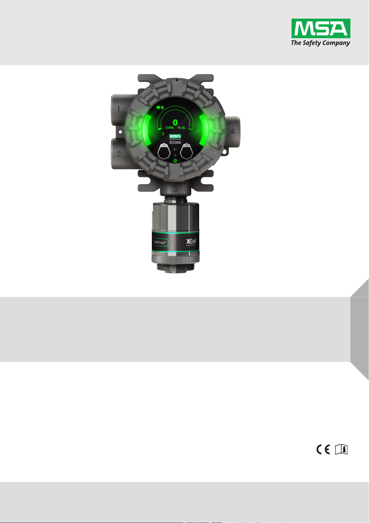
ULTIMA® X5000
Gas Monitor
Order No.: 10177361/06
CR 800000042524

For countries of Russian Federation, Republic of Kazakhstan and Republic of Belarus, the gas detector
will be delivered with a passport document that includes valid approval information. On the CD with
manual instruction attached to the gas detector the user will find the documents "Type Description" and
"Test Method" - appendixes to Pattern Approval Certificate of Measuring instrument, valid in the countries of use.
1000 Cranberry Woods Drive
Cranberry Township, PA 16066
USA
Phone 1-800-MSA-2222
Fax 1-800-967-0398
For your local MSA contacts please go to our website www.MSAsafety.com
©
MSA 2020. All rights reserved

Contents
1 Safety Regulations . . . . . . . . . . . . . . . . . . . . . . . . . . . . . . . . . . . . . . . . . . . . . . . . . . . . . . . . . . . . . . . . . . 5
1.1 Correct Use . . . . . . . . . . . . . . . . . . . . . . . . . . . . . . . . . . . . . . . . . . . . . . . . . . . . . . . . . . . . . . . . . . . 5
1.2 Product Warranty . . . . . . . . . . . . . . . . . . . . . . . . . . . . . . . . . . . . . . . . . . . . . . . . . . . . . . . . . . . . . . . 6
2 Description. . . . . . . . . . . . . . . . . . . . . . . . . . . . . . . . . . . . . . . . . . . . . . . . . . . . . . . . . . . . . . . . . . . . . . . . . 7
2.1 Display . . . . . . . . . . . . . . . . . . . . . . . . . . . . . . . . . . . . . . . . . . . . . . . . . . . . . . . . . . . . . . . . . . . . . . . 7
2.2 No Tool Interface . . . . . . . . . . . . . . . . . . . . . . . . . . . . . . . . . . . . . . . . . . . . . . . . . . . . . . . . . . . . . . . 8
2.3 Bluetooth
2.4 Dual Sensing . . . . . . . . . . . . . . . . . . . . . . . . . . . . . . . . . . . . . . . . . . . . . . . . . . . . . . . . . . . . . . . . . . 8
2.5 Retrofit Installations . . . . . . . . . . . . . . . . . . . . . . . . . . . . . . . . . . . . . . . . . . . . . . . . . . . . . . . . . . . . . 9
2.6 XCell Sensors Optimized for Fixed Gas Applications . . . . . . . . . . . . . . . . . . . . . . . . . . . . . . . . . . . 9
2.7 TruCal Sensing Technology for CO and H
2.8 SafeSwap . . . . . . . . . . . . . . . . . . . . . . . . . . . . . . . . . . . . . . . . . . . . . . . . . . . . . . . . . . . . . . . . . . . . 10
2.9 Housing . . . . . . . . . . . . . . . . . . . . . . . . . . . . . . . . . . . . . . . . . . . . . . . . . . . . . . . . . . . . . . . . . . . . . 10
2.10 Component Overview. . . . . . . . . . . . . . . . . . . . . . . . . . . . . . . . . . . . . . . . . . . . . . . . . . . . . . . . . . . 11
2.11 Label Overview. . . . . . . . . . . . . . . . . . . . . . . . . . . . . . . . . . . . . . . . . . . . . . . . . . . . . . . . . . . . . . . . 11
3 Installation . . . . . . . . . . . . . . . . . . . . . . . . . . . . . . . . . . . . . . . . . . . . . . . . . . . . . . . . . . . . . . . . . . . . . . . . 14
3.1 Installation Warnings - Read before Installation . . . . . . . . . . . . . . . . . . . . . . . . . . . . . . . . . . . . . . . 14
3.2 Reviewing Shipment and Identifying Product Model . . . . . . . . . . . . . . . . . . . . . . . . . . . . . . . . . . . 15
3.3 Product Installation Check List . . . . . . . . . . . . . . . . . . . . . . . . . . . . . . . . . . . . . . . . . . . . . . . . . . . . 15
3.4 Mounting. . . . . . . . . . . . . . . . . . . . . . . . . . . . . . . . . . . . . . . . . . . . . . . . . . . . . . . . . . . . . . . . . . . . . 16
3.4.1 Sensor Mounting Location . . . . . . . . . . . . . . . . . . . . . . . . . . . . . . . . . . . . . . . . . . . . . . . . . . . . . . . 16
3.4.2 Transmitter Mounting Location. . . . . . . . . . . . . . . . . . . . . . . . . . . . . . . . . . . . . . . . . . . . . . . . . . . . 16
3.4.3 Sensor Orientation . . . . . . . . . . . . . . . . . . . . . . . . . . . . . . . . . . . . . . . . . . . . . . . . . . . . . . . . . . . . . 17
3.4.4 Connecting Sensor to Transmitter Housing or Remote Junction Box . . . . . . . . . . . . . . . . . . . . . . 18
3.4.5 Integrated Mounting Points . . . . . . . . . . . . . . . . . . . . . . . . . . . . . . . . . . . . . . . . . . . . . . . . . . . . . . 20
3.4.6 Mounting Points JB5000 Junction Box . . . . . . . . . . . . . . . . . . . . . . . . . . . . . . . . . . . . . . . . . . . . . . 21
3.4.7 2" (50.8 mm) Pipe Mount . . . . . . . . . . . . . . . . . . . . . . . . . . . . . . . . . . . . . . . . . . . . . . . . . . . . . . . . 21
3.4.8 Adjustable Pipe Mount . . . . . . . . . . . . . . . . . . . . . . . . . . . . . . . . . . . . . . . . . . . . . . . . . . . . . . . . . . 22
3.4.9 Duct Mount . . . . . . . . . . . . . . . . . . . . . . . . . . . . . . . . . . . . . . . . . . . . . . . . . . . . . . . . . . . . . . . . . . . 23
3.4.10 Mounting with a Sunshield . . . . . . . . . . . . . . . . . . . . . . . . . . . . . . . . . . . . . . . . . . . . . . . . . . . . . . . 24
3.4.11 Mounting with an SM5000 Sampling Module . . . . . . . . . . . . . . . . . . . . . . . . . . . . . . . . . . . . . . . . . 25
3.5 Installing a Remote Sensor Junction Box. . . . . . . . . . . . . . . . . . . . . . . . . . . . . . . . . . . . . . . . . . . . 26
3.6 Electrical Power Connections. . . . . . . . . . . . . . . . . . . . . . . . . . . . . . . . . . . . . . . . . . . . . . . . . . . . . 27
3.6.1 Electrical Warnings - Read before Connecting Power . . . . . . . . . . . . . . . . . . . . . . . . . . . . . . . . . . 27
3.6.2 Retrofit Applications with UltimaX . . . . . . . . . . . . . . . . . . . . . . . . . . . . . . . . . . . . . . . . . . . . . . . . . 27
3.6.3 Electrical Hardware Requirements. . . . . . . . . . . . . . . . . . . . . . . . . . . . . . . . . . . . . . . . . . . . . . . . . 28
3.6.4 Power Load Requirements and Maximum Mounting Distances. . . . . . . . . . . . . . . . . . . . . . . . . . . 29
3.6.5 Instructions for Power and Analog Output . . . . . . . . . . . . . . . . . . . . . . . . . . . . . . . . . . . . . . . . . . . 34
3.6.6 Relay and Power Connections . . . . . . . . . . . . . . . . . . . . . . . . . . . . . . . . . . . . . . . . . . . . . . . . . . . . 36
®
Wireless Technology . . . . . . . . . . . . . . . . . . . . . . . . . . . . . . . . . . . . . . . . . . . . . . . . . . . 8
S Electrochemical Sensors . . . . . . . . . . . . . . . . . . . . . 9
2
US
4 Operation . . . . . . . . . . . . . . . . . . . . . . . . . . . . . . . . . . . . . . . . . . . . . . . . . . . . . . . . . . . . . . . . . . . . . . . . . 39
4.1 Startup . . . . . . . . . . . . . . . . . . . . . . . . . . . . . . . . . . . . . . . . . . . . . . . . . . . . . . . . . . . . . . .
4.1.1 Initial Startup . . . . . . . . . . . . . . . . . . . . . . . . . . . . . . . . . . . . . . . . . . . . . . . . . . . . . . . . . . . . . . . . . 39
4.1.2 Sensor Warm Up Times . . . . . . . . . . . . . . . . . . . . . . . . . . . . . . . . . . . . . . . . . . . . . . . . . . . . . . . . . 39
4.2 Settings . . . . . . . . . . . . . . . . . . . . . . . . . . . . . . . . . . . . . . . . . . . . . . . . . . . . . . . . . . . . . . . . . . . . . 40
4.2.1 Instrument Settings . . . . . . . . . . . . . . . . . . . . . . . . . . . . . . . . . . . . . . . . . . . . . . . . . . . . . . . . . . . . 41
4.2.2 Sensor Settings . . . . . . . . . . . . . . . . . . . . . . . . . . . . . . . . . . . . . . . . . . . . . . . . . . . . . . . . . . . . . . . 49
4.3 Status Menu . . . . . . . . . . . . . . . . . . . . . . . . . . . . . . . . . . . . . . . . . . . . . . . . . . . . . . . . . . . . . . . . . . 60
4.3.1 Life and Health - XCell H
S and CO Sensors with TruCal Only. . . . . . . . . . . . . . . . . . . . . . . . . . . 60
2
ULTIMA® X5000
. . . . . . . 39
3

5 Calibration . . . . . . . . . . . . . . . . . . . . . . . . . . . . . . . . . . . . . . . . . . . . . . . . . . . . . . . . . . . . . . . . . . . . . . . . 61
5.1 Calibration Equipment . . . . . . . . . . . . . . . . . . . . . . . . . . . . . . . . . . . . . . . . . . . . . . . . . . . . . . . . . . 61
5.2 Calibration Frequency . . . . . . . . . . . . . . . . . . . . . . . . . . . . . . . . . . . . . . . . . . . . . . . . . . . . . . . . . . 63
5.3 Calibration Frequency for XCell Sensors with TruCal (H
5.3.1 XCell Sensors with TruCal and Diffusion Supervision (H2S & CO only) . . . . . . . . . . . . . . . . . . . . 63
5.3.2 XCell Sensors with TruCal without Diffusion Supervision (H
5.4 Calibration Types: Zero vs. Span . . . . . . . . . . . . . . . . . . . . . . . . . . . . . . . . . . . . . . . . . . . . . . . . . . 64
5.5 How to Zero Calibrate XCell Sensors. . . . . . . . . . . . . . . . . . . . . . . . . . . . . . . . . . . . . . . . . . . . . . . 64
5.6 How to Calibrate XCell Sensors . . . . . . . . . . . . . . . . . . . . . . . . . . . . . . . . . . . . . . . . . . . . . . . . . . . 66
5.7 How to Calibrate an Oxygen XCell Sensor . . . . . . . . . . . . . . . . . . . . . . . . . . . . . . . . . . . . . . . . . . 67
5.8 How to Calibrate an XIR PLUS Sensor . . . . . . . . . . . . . . . . . . . . . . . . . . . . . . . . . . . . . . . . . . . . . 67
5.9 XCell Catalytic Bead LOC Over Range . . . . . . . . . . . . . . . . . . . . . . . . . . . . . . . . . . . . . . . . . . . . . 67
5.10 Calibration Confirmation and As Found/As Left Values . . . . . . . . . . . . . . . . . . . . . . . . . . . . . . . . . 67
6 Maintenance. . . . . . . . . . . . . . . . . . . . . . . . . . . . . . . . . . . . . . . . . . . . . . . . . . . . . . . . . . . . . . . . . . . . . . . 68
6.1 ULTIMA XIR PLUS Cleaning Procedure . . . . . . . . . . . . . . . . . . . . . . . . . . . . . . . . . . . . . . . . . . . . 68
6.2 Replacing an XCell Sensor . . . . . . . . . . . . . . . . . . . . . . . . . . . . . . . . . . . . . . . . . . . . . . . . . . . . . . 69
6.3 Clearing a Blockage . . . . . . . . . . . . . . . . . . . . . . . . . . . . . . . . . . . . . . . . . . . . . . . . . . . . . . . . . . . . 71
6.4 Troubleshooting . . . . . . . . . . . . . . . . . . . . . . . . . . . . . . . . . . . . . . . . . . . . . . . . . . . . . . . . . . . . . . . 72
7 Ordering Information. . . . . . . . . . . . . . . . . . . . . . . . . . . . . . . . . . . . . . . . . . . . . . . . . . . . . . . . . . . . . . . . 76
7.1 Replacement Parts. . . . . . . . . . . . . . . . . . . . . . . . . . . . . . . . . . . . . . . . . . . . . . . . . . . . . . . . . . . . . 76
7.2 Accessories . . . . . . . . . . . . . . . . . . . . . . . . . . . . . . . . . . . . . . . . . . . . . . . . . . . . . . . . . . . . . . . .. . 77
S & CO only). . . . . . . . . . . . . . . . . . . . . 63
2
S & CO only). . . . . . . . . . . . . . . . . . 63
2
8 Appendix: Specifications . . . . . . . . . . . . . . . . . . . . . . . . . . . . . . . . . . . . . . . . . . . . . . . . . . . . . . . . . . . . 78
9 Appendix: Calibration Guide for Additional Gases . . . . . . . . . . . . . . . . . . . . . . . . . . . . . . . . . . . . . . . 85
10 Appendix: General Certification Information . . . . . . . . . . . . . . . . . . . . . . . . . . . . . . . . . . . . . . . . . . . . 90
11 Appendix: HART Specific Information . . . . . . . . . . . . . . . . . . . . . . . . . . . . . . . . . . . . . . . . . . . . . . . . . 94
US
ULTIMA® X5000
4

Safety Regulations
1 Safety Regulations
1.1 Correct Use
The ULTIMA X5000 Gas Monitor, hereafter also called device, is a gas monitor for measuring
toxic and combustible gases as well as oxygen. Using sensors, the device tests the ambient air
and triggers the alarm as soon as the gas exceeds a specific concentration level.
WARNING!
Read this manual carefully. The device will perform as designed only if it is used, installed, and
maintained in accordance with the manufacturer's instructions. Otherwise, it could fail to perform
as designed and persons who rely on this device for their safety could sustain serious personal
injury or loss of life.
WARNING!
Do not use silicone-type lubricants in assembling the device and do not allow silicone vapors to
be drawn into the flow system while in operation. Silicone can desensitize the combustible gas
sensor, thereby giving erroneously low readings.
Use only genuine MSA replacement parts when performing any maintenance procedures
provided in this manual. Failure to do so may seriously impair sensor and gas monitoring performance, alter flameproof/explosion proof characteristics or void agency approvals.
Failure to follow the above warnings can result in serious personal injury or loss of life.
This device complies with Part 15 of the FCC Rules. Operation is subject to the
following two conditions:
• device may not cause harmful interference, and
• device must accept any interference received, including interference that may cause
undesired operation.
This equipment has been tested and found to comply with the limits for a Class A digital
device, pursuant to Part 15 of the FCC Rules. These limits are designed to provide
reasonable protection against harmful interference when the equipment is operated in
a commercial environment. This equipment generates, uses, and can radiate radio
frequency energy and, if not installed and used in accordance with the instruction
manual, may cause harmful interference to radio communications. Operation of this
equipment in a residential area is likely to cause harmful interference in which case the
user will be required to correct the interference at the user’s expense.
NOTICE
This is a Class A product in accordance with CISPR 22. In a domestic environment, this product
may cause radio interference, in which case the user may be required to take adequate measures.
NOTICE
The XCell sensor refers to the sensor portion of the Digital Sensor throughout this manual.
FCC Warning Statements
Changes or modifications not expressly approved by the manufacturer could void the user's
authority to operate the equipment.
Industry Canada (IC) Warning Statements
The installer of this radio equipment must ensure that the antenna is located or pointed such that
it does not emit RF field in excess of Health Canada limits for the general population; consult
Safety Code 6, obtainable from Health Canada's website www.hc-sc.gc.ca.
US
ULTIMA® X5000
5

Safety Regulations
1.2 Product Warranty
ITEM WARRANTY PERIOD
MSA warrants that this product will be free from
mechanical defects and faulty workmanship for the
period specified in this table for each component,
ULTIMA X5000 Gas Monitor
Main Transmitter Housing and PCBA 2 years from date of shipment.
XCell Sensors 3 years from date of shipment.
XIR PLUS 5 years on electronics. 10 years on IR source bulb.
This warranty does not cover filters, fuses, etc. Certain other accessories not specifically listed
here may have different warranty periods. This warranty is valid only if the product is maintained
and used in accordance with Seller's instructions and/or recommendations. The Seller shall be
released from all obligations under this warranty in the event repairs or modifications are made by
persons other than its own or authorized service personnel or if the warranty claim results from
physical abuse or misuse of the product. No agent, employee or representative of the Seller has
any authority to bind the Seller to any affirmation, representation or warranty concerning this
product. Seller makes no warranty concerning components or accessories not manufactured by
the Seller, but will pass on to the Purchaser all warranties of manufacturers of such components.
THIS WARRANTY IS IN LIEU OF ALL OTHER WARRANTIES, EXPRESSED, IMPLIED OR
STATUTORY, AND IS STRICTLY LIMITED TO THE TERMS HEREOF. SELLER SPECIFICALLY DISCLAIMS ANY WARRANTY OF MERCHANTABILITY OR OF FITNESS FOR A
PARTICULAR PURPOSE.
Exclusive Remedy
It is expressly agreed that Purchaser's sole and exclusive remedy for breach of the above
warranty, for any tortious conduct of Seller, or for any other cause of action, shall be the replacement at Seller's option, of any equipment or parts thereof, which after examination by Seller is
proven to be defective. Replacement equipment and/or parts will be provided at no cost to
Purchaser, F.O.B. Seller's Plant. Failure of Seller to successfully replace any nonconforming
equipment or parts shall not cause the remedy established hereby to fail of its essential purpose.
Exclusion of Consequential Damage
Purchaser specifically understands and agrees that under no circumstances will seller be liable to
purchaser for economic, special, incidental or consequential damages or losses of any kind whatsoever, including but not limited to, loss of anticipated profits and any other loss caused by reason
of non-operation of the goods. This exclusion is applicable to claims for breach of warranty,
tortious conduct or any other cause of action against seller.
provided it is maintained and used in accordance with
MSA's instructions and/or recommendations. Guarantee
shall not exceed the indicated warranty period plus six
months from the date of manufacture.
US
ULTIMA® X5000
6
2 Description
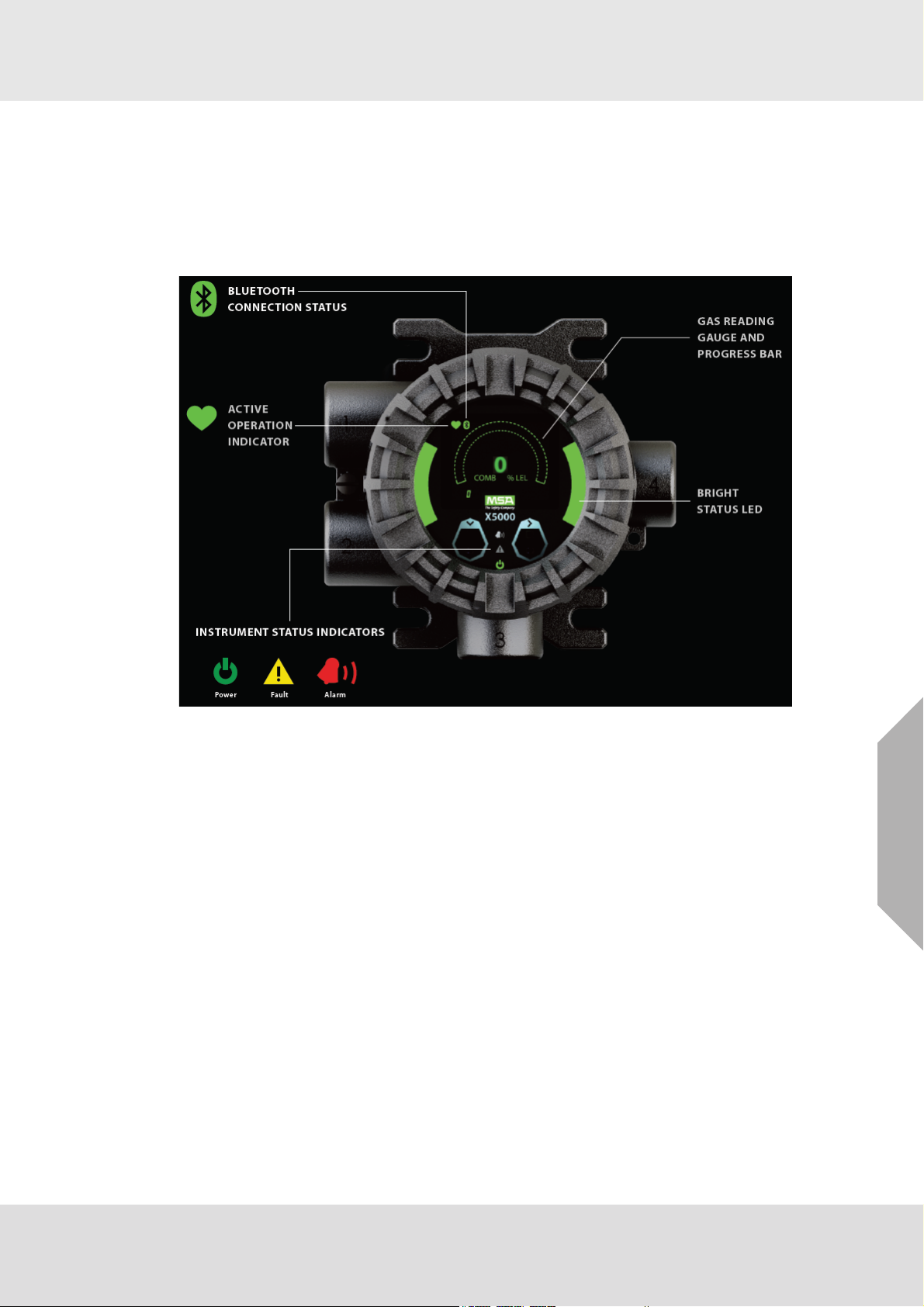
2.1 Display
The ULTIMA X5000 utilizes an Organic LED (OLED) display which is capable of being seen from
a distance of up to 50 ft (15 m) depending on conditions. The OLED display provides clear and
crisp information in a variety of languages. The gas reading gauge, which wraps around the live
reading area, mimics the reading as a percent of full scale and is also used as a progress bar
during operations which require a countdown.
Description
Fig. 1 OLED Display
In addition to the OLED display, the ULTIMA X5000 also employs green, yellow and red LEDs on
the side and lower middle of its face. These are used to signal normal operating conditions, fault
conditions and alarm conditions.
The ULTIMA X5000 will go into “Eco-Mode” after 3 minutes of no interaction and if not in an alarm
condition. While in Eco-Mode, the main display will power down and the status LED's will remain
illuminated to determine that the device is not in an alarm condition. The OLED display can be
powered up by touching either of the two EZ touch buttons on the front display.
US
ULTIMA® X5000
7
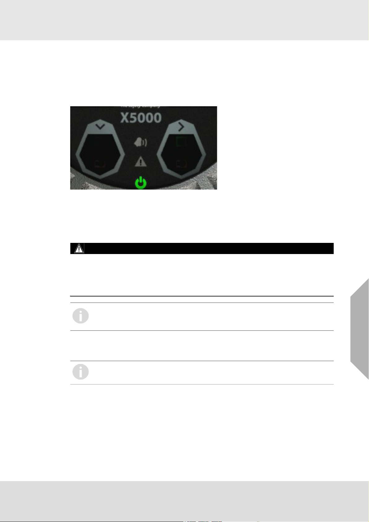
2.2 No Tool Interface
The ULTIMA X5000 does not require any tools or third party devices to change settings, reset
alarms or perform any maintenance feature. The EZ touch buttons work through the glass and do
not require opening the explosion proof enclosure. The EZ touch buttons work with bare fingers
or with gloved hands, so long as the gloves are not black. The down arrow is used for scrolling,
while the right arrow is used for selecting options. See section 4 for more information on navigating
the menu with the EZ touch buttons.
Fig. 2 ULTIMA X5000 Interface
2.3 Bluetooth® Wireless Technology
The ULTIMA X5000 can be ordered with Bluetooth communication. Using the X/S Connect App
on an appropriate smart phone or tablet, you are able to interface with the ULTIMA X5000 in a
larger and more user friendly setting. Connecting via Bluetooth enables communication with transmitter up to 70 feet (21 m) away.
Description
WARNING!
Bluetooth Operation is dependent upon signal availability of the wireless service(s) necessary to
maintain the communication link. Loss of wireless signal will prevent communication of alarms and
other information to linked devices. Take appropriate precautions in the event a loss of wireless
signal occurs.
Failure to follow the above warning can result in serious personal injury or loss of life.
If the device was not ordered with Bluetooth it cannot be upgraded.
If ordered with Bluetooth, the device will be shipped with Bluetooth enabled. See
section 4 for instructions on disabling Bluetooth.
The ULTIMA X5000 and user provided communication device will need to be paired. This requires
both devices to be in range and for a pairing sequence inputting a 6 digit pairing code. The instructions will be displayed on both the ULTIMA X5000 and communication device.
There are communication devices capable of being used in classified areas. Please
contact your MSA representative for additional information.
2.4 Dual Sensing
The ULTIMA X5000 is capable of communicating with and displaying information for two sensors
at a time. There are no restrictions to the type of sensors connected to the device.
The ULTIMA X5000 Gas Monitor generates two discrete analog outputs; one for each sensor
connected to the transmitter. The analog output associated with Sensor 1 also has the digital
HART (Highway Addressable Remote Transducer) communication superimposed on the analog
signal. If two sensors are connected, the digital HART communication carries information for both
sensors.
US
ULTIMA® X5000
8

2.5 Retrofit Installations
The ULTIMA X5000 has the conduit entries located in the exact same orientation and distance
from the wall and the mounting holes for attaching to a wall are identical to the Ultima X.
2.6 XCell Sensors Optimized for Fixed Gas Applications
XCell toxic and combustible cat bead sensors are developed and manufactured by MSA. Now
optimized for fixed gas applications, the XCell sensor platform is available in the ULTIMA X5000
and provides multiple benefits, including a standard 3-year warranty on all XCell sensors.
One important optimization for fixed gas was incorporating the GM catalytic bead into the XCell
sensor.
The XCell Oxygen sensor does not use lead, but rather a non-consuming reaction chemistry. The
XCell Oxygen sensor is expected to last well over 3-years and can be safely stored on the shelf
for at least 1 year without sensor performance degradation. Changes in barometric pressure
across the range of 86 kPa - 108 kPa have a negligible effect on the operation of the sensor.
2.7 TruCal Sensing Technology for CO and H
Using patented pulse check technology and proprietary Adaptive Environmental Compensation
(AEC) algorithms, all XCell sensors with TruCal verify operation by actively adjusting the sensor
output for changes in sensitivity. Some XCell sensors with TruCal also include Diffusion Supervision, which monitors the sensor inlet for obstructions that could prevent gas from reaching the
sensor.
Every six hours, an electrical pulse stimulates the XCell sensor similar to having actual calibration
gas applied, providing a snapshot of the sensor’s sensitivity at the time of the pulse. Using this
sensitivity snapshot, the sensor can diagnose sensor failures like electrode poisoning, electrolyte
leaking, or electrical connectivity issues.
AEC uses the sensitivity snapshots provided by the pulse check to adjust sensor output, compensating for environmental impacts on sensor accuracy. If the AEC adjustment is greater than
expected based on typical environmental impact variations, the transmitter LED’s will slowly flash
GREEN, alerting users that the sensor should be calibrated to reset the AEC cycle. Users can also
enable a Calibration Alert function that will send a milli-amp signal on the analog output to the
control room. The result is a sensor that actively self-monitors for operation and accuracy, with far
fewer manual calibrations.
Diffusion supervision actively monitors the sensor inlet for obstructions. If an obstruction is
detected, the sensor will go into a fault mode to alert users and the control room that it is not seeing
gas due to an obstruction. Objects residing directly on or in the sensor inlet that result in a significant impact to the gas path are very likely to be detected by Diffusion Supervision. Examples
include paint, tape, water, and dirt. Small amounts of these materials can be visible on the inlet
while not impacting the gas path enough to trigger a Diffusion Supervision Fault. A fault signal will
only be sent out when the system determines that the amount of material that has accumulated
on or inside the sensor inlet is negatively affecting the gas path.
Actual TruCal sensor performance will depend on the application, background gas exposure, and
environment. To validate XCell sensors with TruCal, it is recommended that users follow their
regular calibration cycle and record the “as found” and “as left” values. This data can be used to
extend the time between calibrations depending on the required specification of the application.
S Electrochemical Sensors
2
Description
US
ULTIMA® X5000
9

2.8 SafeSwap
The ULTIMA X5000 comes with patented SafeSwap technology, which allows users to change or
replace XCell sensors without needing to power down the instrument. For added convenience, the
ULTIMA X5000 comes with Swap Delay enabled by default; a feature that gives users a 2 minute
window to change sensors without triggering a fault condition. For more information on SafeSwap
and Swap Delay, see section 4.2.1.
WARNING!
As part of the product certification, it was verified that optional communication functions of this
gas detection instrument while operating at the maximum transaction rate do not adversely
affect the gas detection operation and functions of the instrument. The product certification,
however, does not include or imply approval of the SafeSwap feature, communications
protocol or functions provided by the software of this instrument or of the communications
apparatus and software connected to this instrument.
Follow the warnings below when removing or replacing sensors. Reference 2.10 for compo-
nent overview.
- Never remove or replace a Sensor Body Assembly or an Ultima XIR Plus while under power
or when explosive hazards are present.
- Confirm that the area is free of explosive hazards before removing or replacing an XCell
Sensor under power.
- To remove an XCell Sensor, unscrew XCell Sensor three full turns, wait 10 seconds, and then
remove the XCell Sensor completely.
Description
Failure to follow the above warnings can result in serious personal injury or loss of life.
2.9 Housing
The ULTIMA X5000 comes in 316 Stainless Steel for the highest corrosion resistance. Both ¾”
NPT and M25 conduit entries are available. To attach a sensor to an M25 housing, an M25
adapter is required and will be included with the shipment. An integral surface mount bracket can
be used to mount directly into the wall surface or used with a U-Bolt for mounting to a 2” pipe.
Custom tags are available and easily attach to an integral ring.
US
ULTIMA® X5000
10
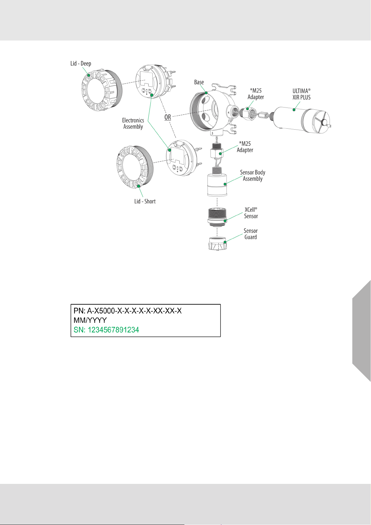
2.10 Component Overview
Description
Fig. 3 Component Overview
* Only used with M25 bases
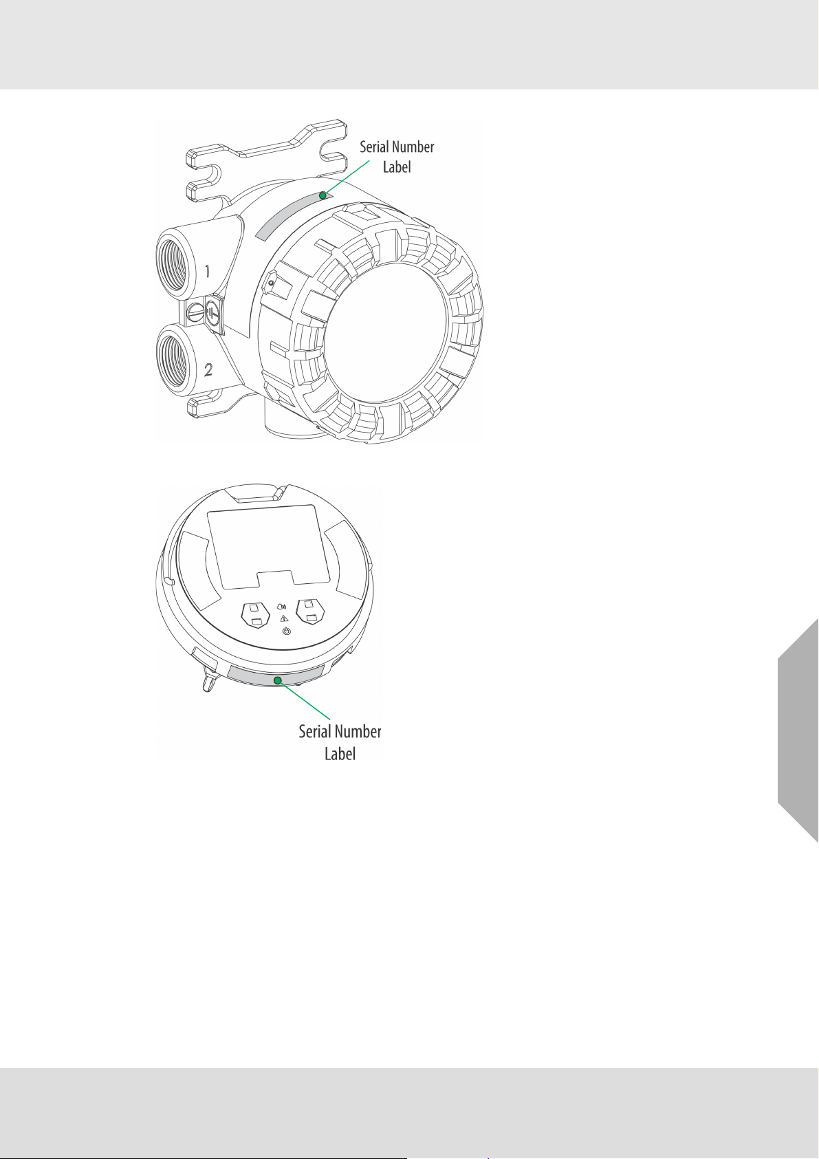
2.11 Label Overview
Serial number is located where shown (highlighted in green). Actual number of digits may be
different.
Fig. 4 Serial Number Label
US
ULTIMA® X5000
11
Description
Fig. 5 Transmitter - Position of Labels
Fig. 6 Board Stack - Position of Labels
US
ULTIMA® X5000
12
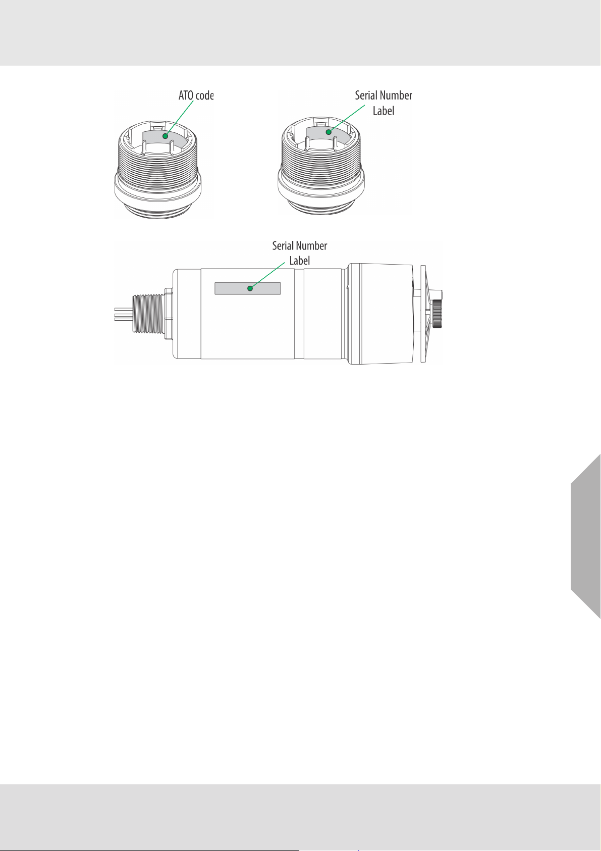
Fig. 7 Digital Sensor - Position of Labels
Description
Fig. 8 XIR Plus - Position of Labels
US
ULTIMA® X5000
13

3 Installation
3.1 Installation Warnings - Read before Installation
WARNING!
Refer to manual addendum (Part Number 10182779) for Certification Information and addi-
tional safety information before installation and operation.
Some Digital Sensors are provided in a fritless sensor housing. The fritless sensor housing is
labeled as Div 2 or Zone 2 and is approved for Div 2 or Zone 2 installations only. The protection
method is Non-incendive or Type n respectively. Ensure all components are approved for the
wiring method being used and in accordance with the National Electrical Code of the country
of use, any applicable local regulations, this manual and the addendum to the manual.
As part of the product certification, it was verified that optional communication functions of this
gas detection instrument while operating at the maximum transaction rate do not adversely
affect the gas detection operation and functions of the instrument. The product certification,
however, does not include or imply approval of the SafeSwap feature, communications
protocol or functions provided by the software of this instrument or of the communications
apparatus and software connected to this instrument.
Follow the warnings below when removing or replacing sensors. Reference Fig. 3 for compo-
nent overview.
- Never remove or replace a Sensor Body Assembly or an Ultima XIR Plus while under power
or when explosive hazards are present.
- Confirm that the area is free of explosive hazards before removing or replacing an XCell
Sensor under power.
- To remove an XCell Sensor, unscrew XCell Sensor three full turns, wait 10 seconds, and then
remove the XCell Sensor completely.
Plug all unused conduit entries with a suitably certified blanking/stopping plug.
Do not paint the device. Avoid painting in areas where the ULTIMA X5000 and remote sensor
junction box are located. If painting is required in an area where an ULTIMA X5000 or remote
sensor has been installed, exercise caution to ensure paint is not deposited on the sensor inlet
fitting. Paint solvents can also cause an alarm condition to occur or potentially poison electrochemical sensors.
The H
- Alcohols (methanol, ethanol, isopropanol)
- Nitrogen dioxide (NO
- Chlorine (Cl
- Paint solvents (acetone, turpentine, toluene, mineral spirits, etc.)
The CO Digital Sensor may be adversely affected by the following substances:
- Alcohols (methanol, ethanol, isopropanol)
- Paint solvents (acetone, turpentine, toluene, mineral spirits, etc.)
The O
- Long term exposure to low levels of Acetylene
- Paint solvents (acetone, turpentine, toluene, mineral spirits, etc.) in high concentrations larger
than 1000 ppm or prolonged exposure to lower concentrations
Prolonged exposure of the H
in gas measurement readings of H
present.
It is not recommended to expose the O
containing Oxygen levels above 30% (v/v) or below 5% (v/v). The O
concentrations below 5% (v/v) but not for prolonged periods of time.
Protect the device from extreme vibration.
Do not mount the sensing head in direct sunlight without a sunshield (Part Number 10180254).
The ULTIMA XIR PLUS Sensor contains no user- or field-serviceable parts and must be
returned to the factory for repair. Any attempt to open the sensor will damage the unit and void
the warranty.
S Digital Sensor may be adversely affected by the following substances:
2
)
)
2
Digital Sensor may be adversely affected by the following substances:
2
2
S Digital Sensor to humidity levels of 5% RH or lower will result
2
S that are greater than the actual gas concentration
2
, H2S and CO Digital Sensors to environments
2
sensor will operate at
2
Installation
US
Failure to follow the above warnings can result in serious personal injury or loss of life.
ULTIMA® X5000
14
NOTICE
When installing the XIR PLUS sensor, under no circumstances should a pry-bar be applied to the
two legs that support the unit's reflectors during installation or removal of the sensor. Applying
force to the legs can permanently damage the XIR PLUS sensor.
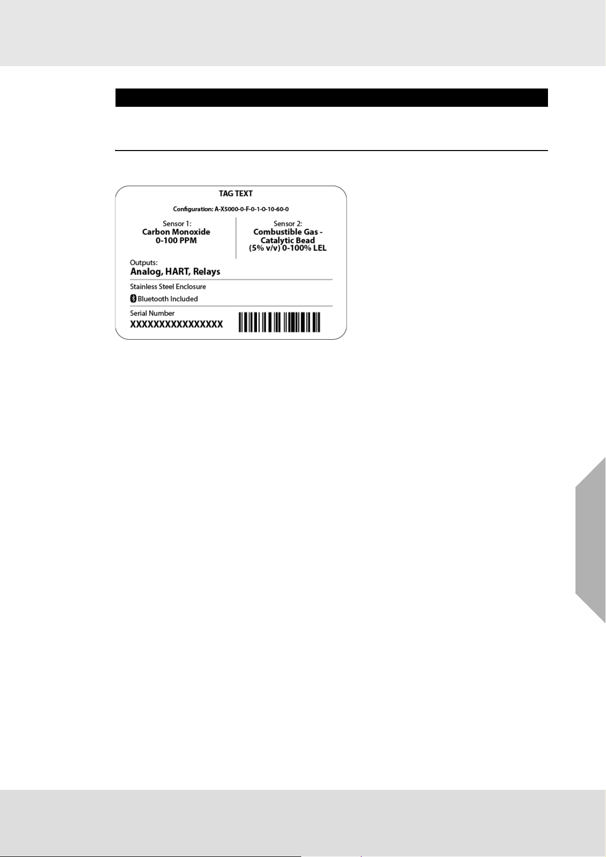
3.2 Reviewing Shipment and Identifying Product Model
To determine your sensor type and options, check the shipping carton.
Installation
Fig. 9 Shipping Label
The device is not shipped with the sensors attached to the housing. The XIR PLUS is a one piece
sensor, but all other sensors are comprised of two parts; the Sensor Body Assembly and the XCell
Sensor. Check the sensor details before attaching to the device housing to ensure that the correct
sensor type is being installed. The sensor details are listed on the inside of the XCell Sensor.
Unscrew the XCell Sensor from the Sensor Body Assembly and check the label on the inside for
gas type, range, replacement ATO configuration, serial number, and firmware revision number.
3.3 Product Installation Check List Before Installation
• Review national electrical codes
• Review local procedural and building codes
• Determine optimum transmitter placement
• Determine wire requirements
• Determine mounting hardware requirements
• Review approvals and ensure suitability for installation
Mounting
• Attach appropriate sensor to housing or junction box (see section 3.4.3 for proper sensor orien-
tation)
• Mount transmitter or junction box using appropriate mounting hardware
• Confirm free air flow around the sensor
US
ULTIMA® X5000
15

3.4 Mounting
WARNING!
Refer to manual addendum (Part Number 10182779) for Certification Information before installation.
Some toxic gases are provided in a fritless sensor housing. The fritless sensor housing is labeled
as Div 2 or Zone 2 and is approved for Div 2 or Zone 2 installations only. The protection method
is Nonincendive or Type n respectively. Ensure all components are approved for the wiring
method being used and in accordance with the National Electrical Code of the country of use, any
applicable local regulations, this manual and the addendum to the manual.
Failure to follow the above warnings can result in serious personal injury or loss of life.
3.4.1 Sensor Mounting Location
The best location for the transmitter and the sensor may not be the same location. Sensors should
be placed in a location where a gas leak is most likely to be detected. When the best sensor placement would not allow the transmitter display to be easily viewed or accessed, a remote junction
box can be used to mount the sensor remotely from the transmitter, allowing both to be installed
in the optimum location.
Two main factors should be considered when choosing a sensor location. The first is the density
of the target gas relative to the air. Gases, such as propane, that are heavier than air should be
placed near ground level while gases that are lighter than air should be placed above potential
leak sources.
Optimum sensor placement will depend on the surrounding processing equipment, such as pipes,
valves, or turbines. MSA offers a gas and flame mapping service that systematically evaluates
potential sources of leaks and recommends detector quantity and placement to create the most
effective detection system.
3.4.2 Transmitter Mounting Location
The transmitter display should be mounted so that the screen is visible and easily accessed after
installation. The electronics assembly inside the metal enclosure can be repositioned in any of the
four self-aligning interior holes to ensure the display is properly oriented and to provide maximum
flexibility for using conduit entries.
Installation
ULTIMA® X5000
US
16
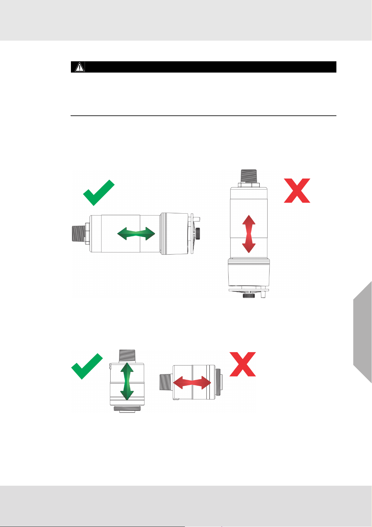
3.4.3 Sensor Orientation
WARNING!
Mount the XIR PLUS with the sensor inlet fitting extended horizontally from the main enclosure
(Fig. 10) to prevent the build-up of particulate or liquid matter on the monitor's optical surfaces.
Mount the digital sensor with the sensor inlet fitting (Fig. 11) pointed downward; otherwise, the
inlet may become clogged with particulate matter or liquids.
Failure to follow the above warnings may result in serious personal injury or loss of life.
Sensor orientation will depend on the sensor type. If mounting an ULTIMA XIR PLUS sensor,
whether locally on the transmitter or via remote junction box, the sensor should be mounted horizontally. If the ULTIMA XIR PLUS sensor is not mounted horizontally, the sensor will be prone to
more frequent beam blocking issues due to accumulated dust and condensation on the surface
of the ULTIMA XIR PLUS sensor. Fig. 10 shows the correct and incorrect mounting orientations
for the ULTIMA XIR PLUS.
Installation
Fig. 10 Correct and Incorrect Mounting Orientations for ULTIMA XIR PLUS Sensor
All other sensors including electrochemical, combustible catalytic bead, and oxygen sensors
should be mounted vertically, with the gas inlet pointed downward. If the sensor is not mounted
with the gas inlet facing down, it is more likely to become clogged with particulate matter or liquids.
Fig. 11 shows the correct and incorrect mounting orientation for digital sensors.
Fig. 11 Correct and Incorrect Mounting Orientation for Digital Sensors
US
ULTIMA® X5000
17
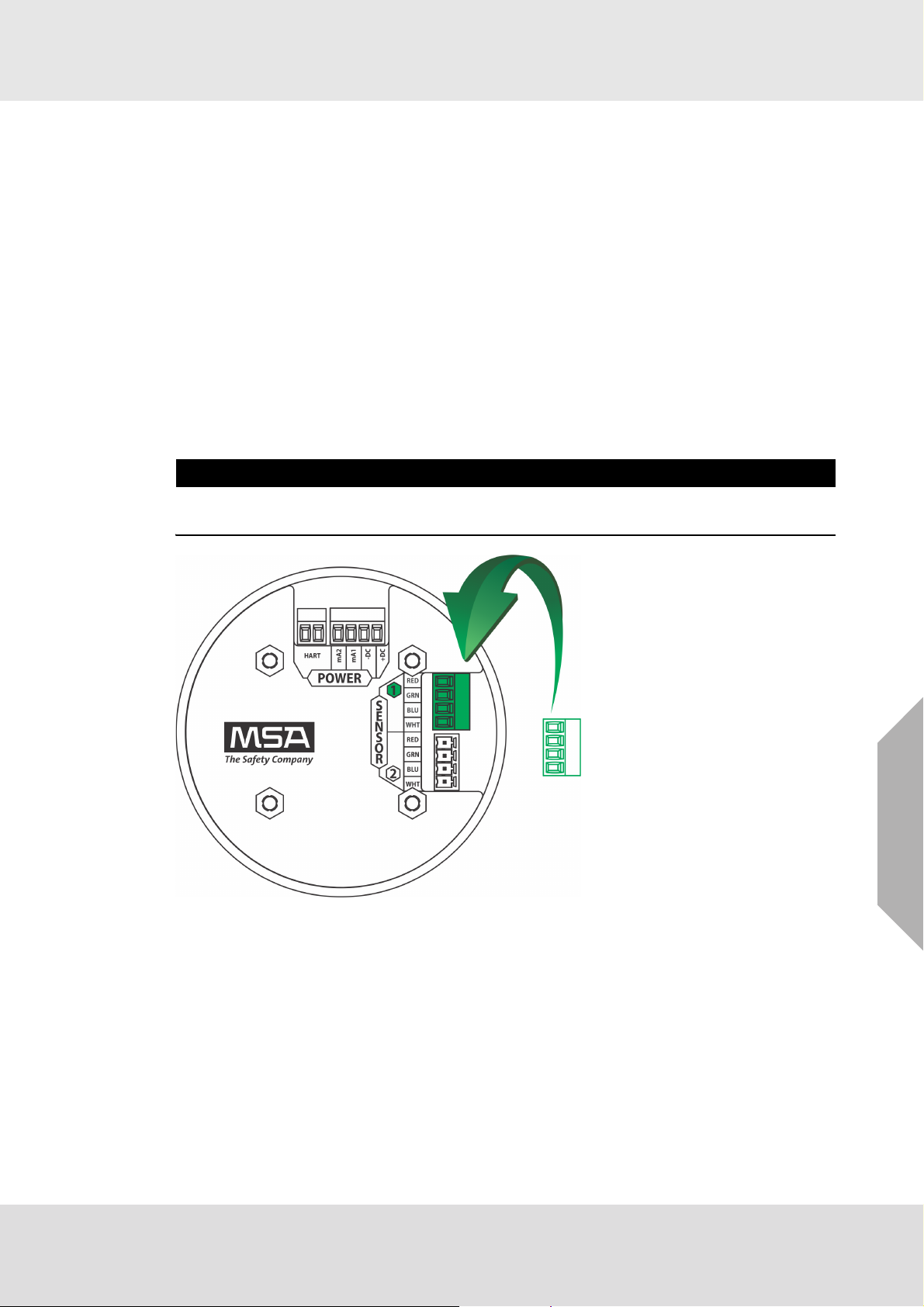
3.4.4 Connecting Sensor to Transmitter Housing or Remote Junction Box
Sensors are not shipped attached to the main enclosure or junction box. All sensor modules interface with the transmitter via a digital four-terminal connection. Up to two sensors can be
connected to a single transmitter, with each sensor getting a dedicated analog (4-20 mA) output.
Consider the sensor dimensions when choosing a mounting location for the transmitter or junction
box.
To connect the sensor:
(1) Turn the transmitter or junction box lid counterclockwise to remove
(2) Pull on the metal bail to remove the board stack and expose wiring connections.
(3) Route the cable from the sensor through a conduit entry hole in the enclosure so that the
sensor is oriented in the correct position (see section 3.4.3 for details).
(Repeat to attach a second sensor to the ULTIMA X5000 transmitter).
(4) Connect the sensor to the "Sensor 1" position on the electronics assembly.
a) If using a second sensor, connect it to the “Sensor 2” position.
NOTICE
If only using one sensor, and it is connected to “Sensor 2” position, the ULTIMA X5000 will enter
Sensor Missing fault. See Disable Sensor in section 4.2.2 for details on how to clear this fault.
Installation
Fig. 12 Connecting Sensor to the Stack
Note: Sensor connectors come pre-wired on the sensor body.
ULTIMA® X5000
US
18
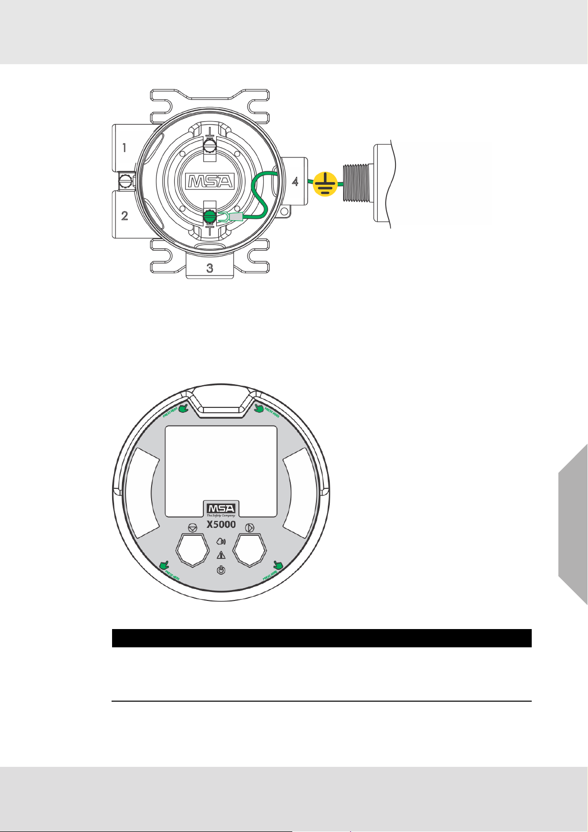
Fig. 13 Grounding Sensor to Transmitter Housing
(5) Verify the sensor connector is firmly seated on the terminal board.
Installation
(6) Attach the sensor's ground to either of the grounding screws inside the ULTIMA X5000
housing.
(7) Replace the board stack legs into the four depressions in the housing. Push firmly on the
board stack where indicated (see Fig. 14).
US
Fig. 14 Highlighted Areas Show Where to Press when Replacing a Board Stack
NOTICE
Avoid pressing on the left and right areas where the LEDs are located. Pressing directly on the
display will damage the display and will void the warranty.
Ensure that the electronics assembly is fully engaged in the mounting holes. If not fully seated,
the user interface buttons may not function properly.
(8) Replace the cover by turning clockwise.
ULTIMA® X5000
19
3.4.5 Integrated Mounting Points
The ULTIMA X5000 transmitter can be surface mounted without any additional brackets using the
integrated mounting tabs.
Fig. 15 Internal Mounting Tabs (not compatible with ULTIMA XIR PLUS Sensors)
An supplementary mounting bracket is required for surface mounting the ULTIMA X5000 with an
attached ULTIMA XIR PLUS sensor.
Installation
Fig. 16 Mounting Bracket for ULTIMA X5000 (compatible with ULTIMA XIR PLUS Sensors)
ULTIMA® X5000
US
20
3.4.6 Mounting Points JB5000 Junction Box
The JB5000 junction box can be mounted directly using the 4 integrated 10-32 threaded holes on
the back of the enclosure or with the use of a mounting bracket (Part Number 10206570).
Fig. 17 JB5000 bracket attachment
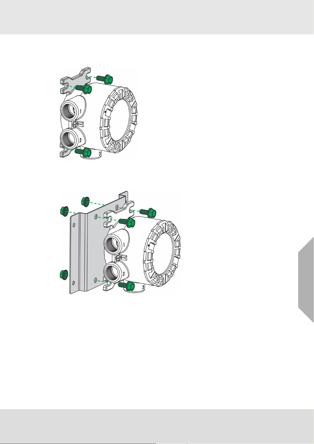
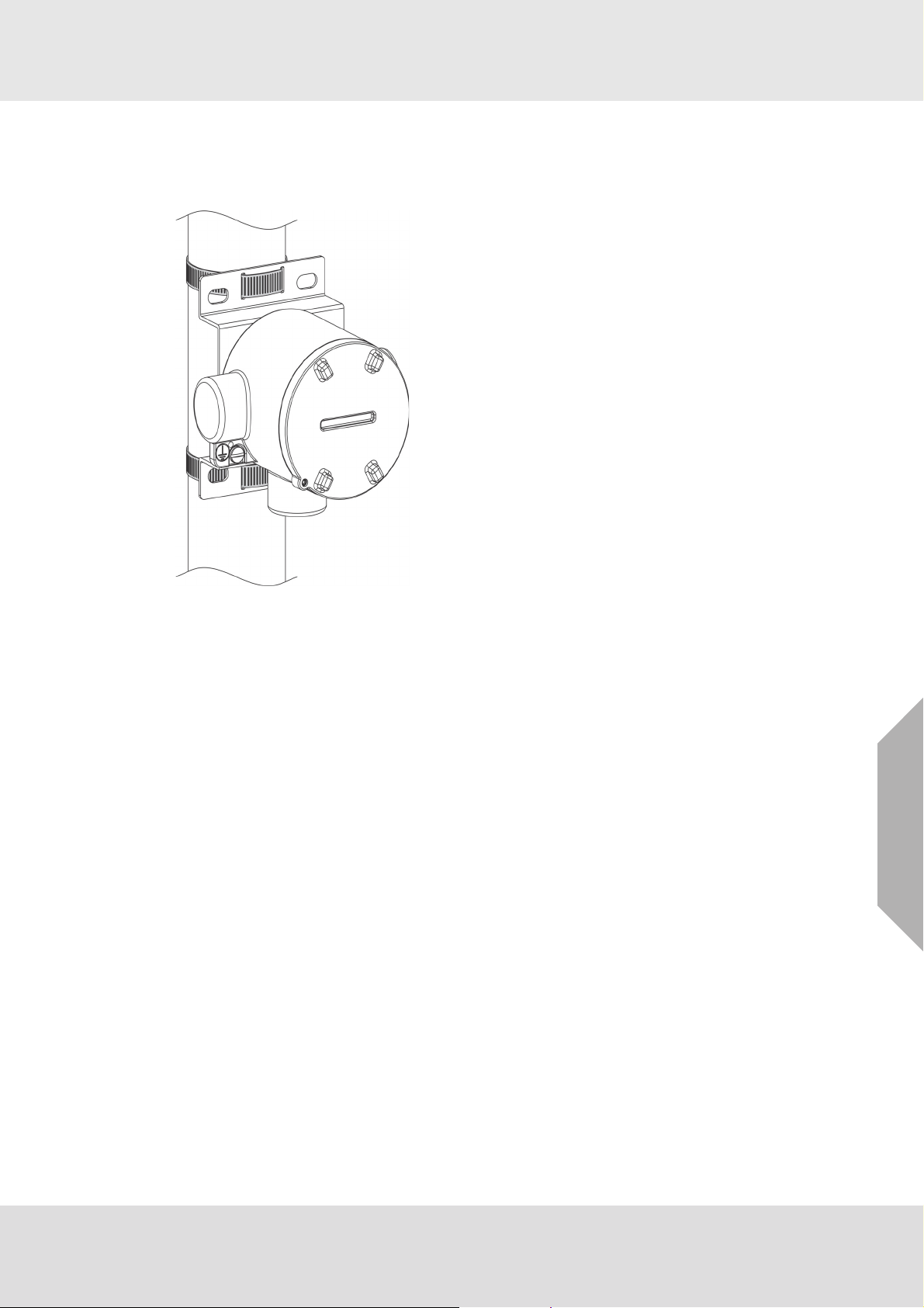
3.4.7 2" (50.8 mm) Pipe Mount
The integrated mounting tabs on the device housing can be mounted to a 2" (50,8 mm) pipe using
a standard U-bolt. MSA provides U-bolts as an optional accessory (Part Number 10179873),
however any 2” (50.8 mm) pipe U-bolt rated for the weight and dimensions of the ULTIMA X5000
can be used.
Installation
Fig. 18 2" Pipe Mount with U-Bolt
ULTIMA® X5000
US
21
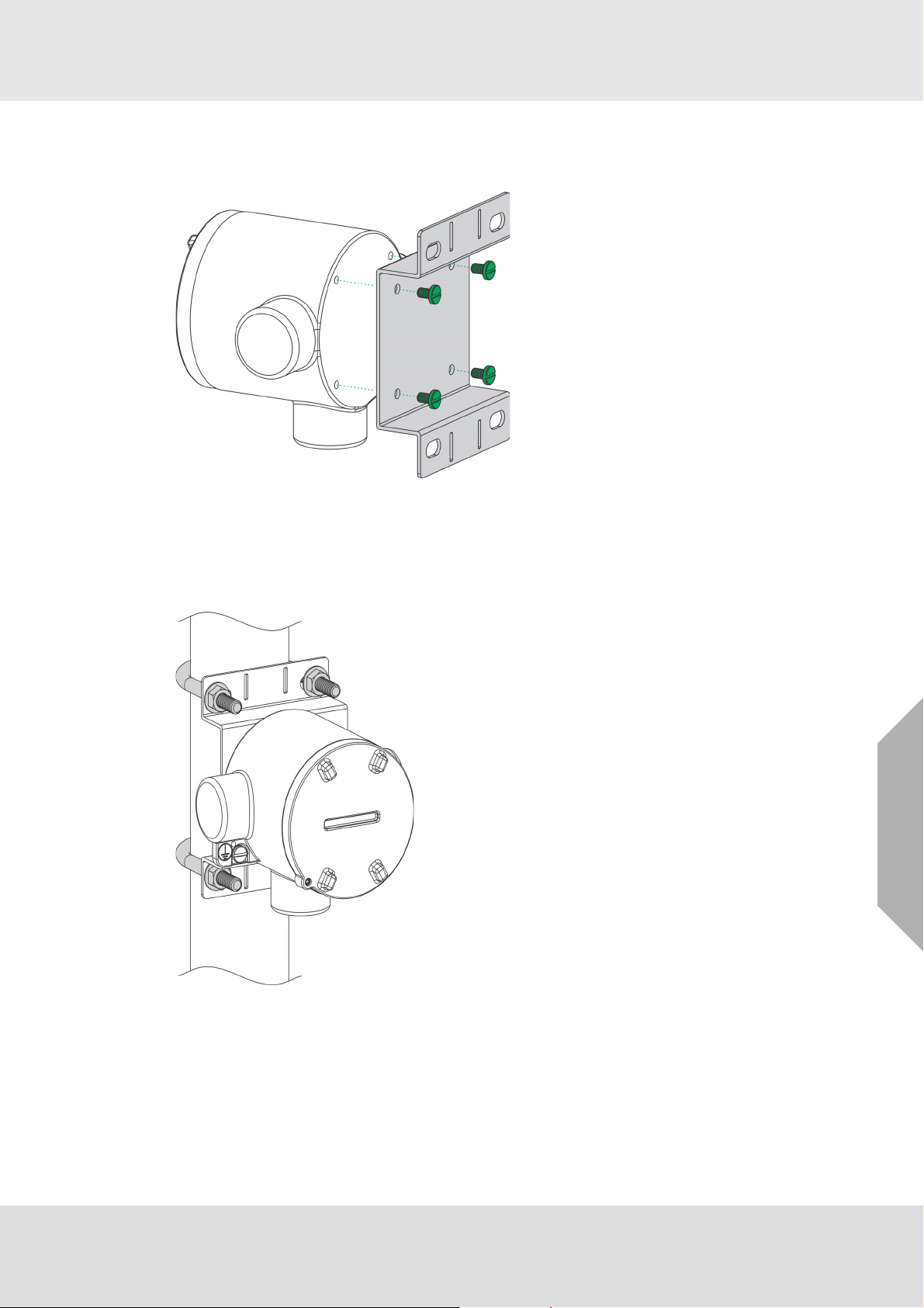
3.4.8 Adjustable Pipe Mount
A Universal Pipe Mount Kit (Part Number 10176946) can be used to mount the ULTIMA X5000
on pipes ranging from 1-6” (20-150 mm) in diameter. Two brackets are mounted over top of the
integrated mounting tabs and fitted with an adjustable pipe band (not included).
Installation
Fig. 19 Adjustable Pipe Mount
US
ULTIMA® X5000
22
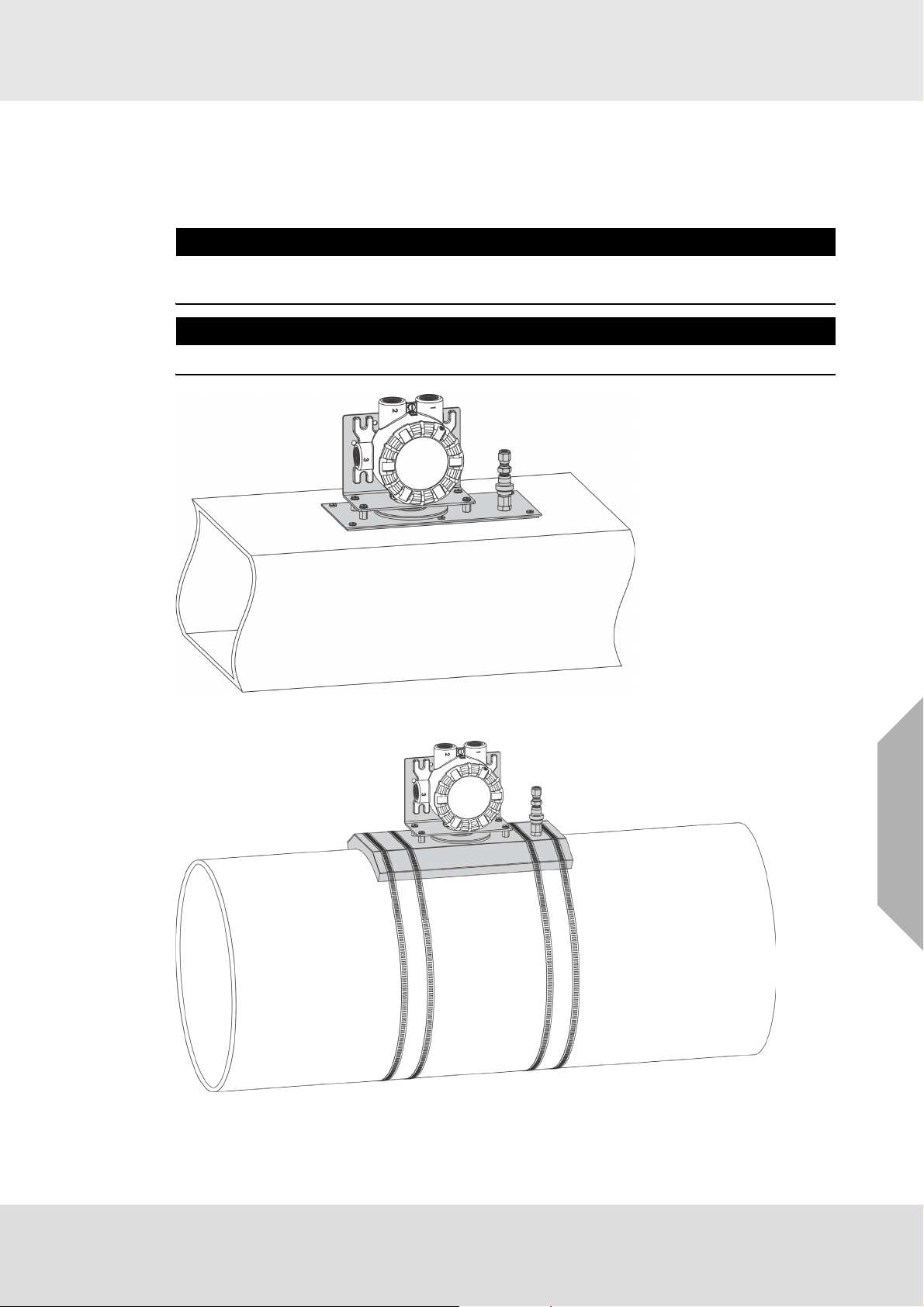
3.4.9 Duct Mount
Duct mount kits are available for monitoring atmosphere inside flat or round ducts. Round duct
mount kits are available for small ducts 12-20" (305-508 mm) in diameter (Part Number
10179124) and large ducts 20-40" (508-1016 mm) in diameter (Part Number 10179321). The flat
duct mount (Part Number 10176947) is universal for flat ducts.
NOTICE
Consider the sensor type before choosing a duct mount location. ULTIMA XIR Plus sensors
should be mounted horizontally and all other sensors should be mounted vertically.
NOTICE
Air flow in the duct must be zero to ensure proper calibration.
Installation
Fig. 20 Flat Duct Mount
Fig. 21 Round Duct Mount
US
ULTIMA® X5000
23
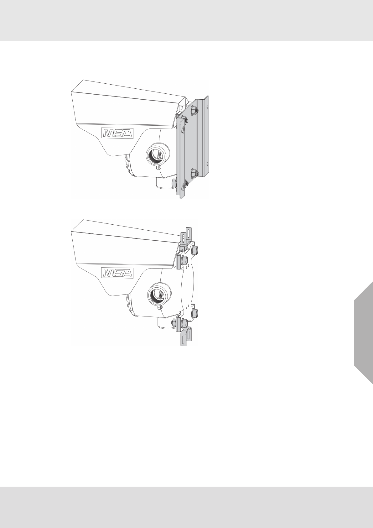
3.4.10Mounting with a Sunshield
A sunshield is required to protect the ULTIMA X5000 from direct sun light
(Part Number 10180254). The sunshield can be used in any of the mounting configurations.
Installation
Fig. 22 Sunshield with Wall Mounting Bracket
Fig. 23 Sunshield with Universal Pipe Mount
US
ULTIMA® X5000
24
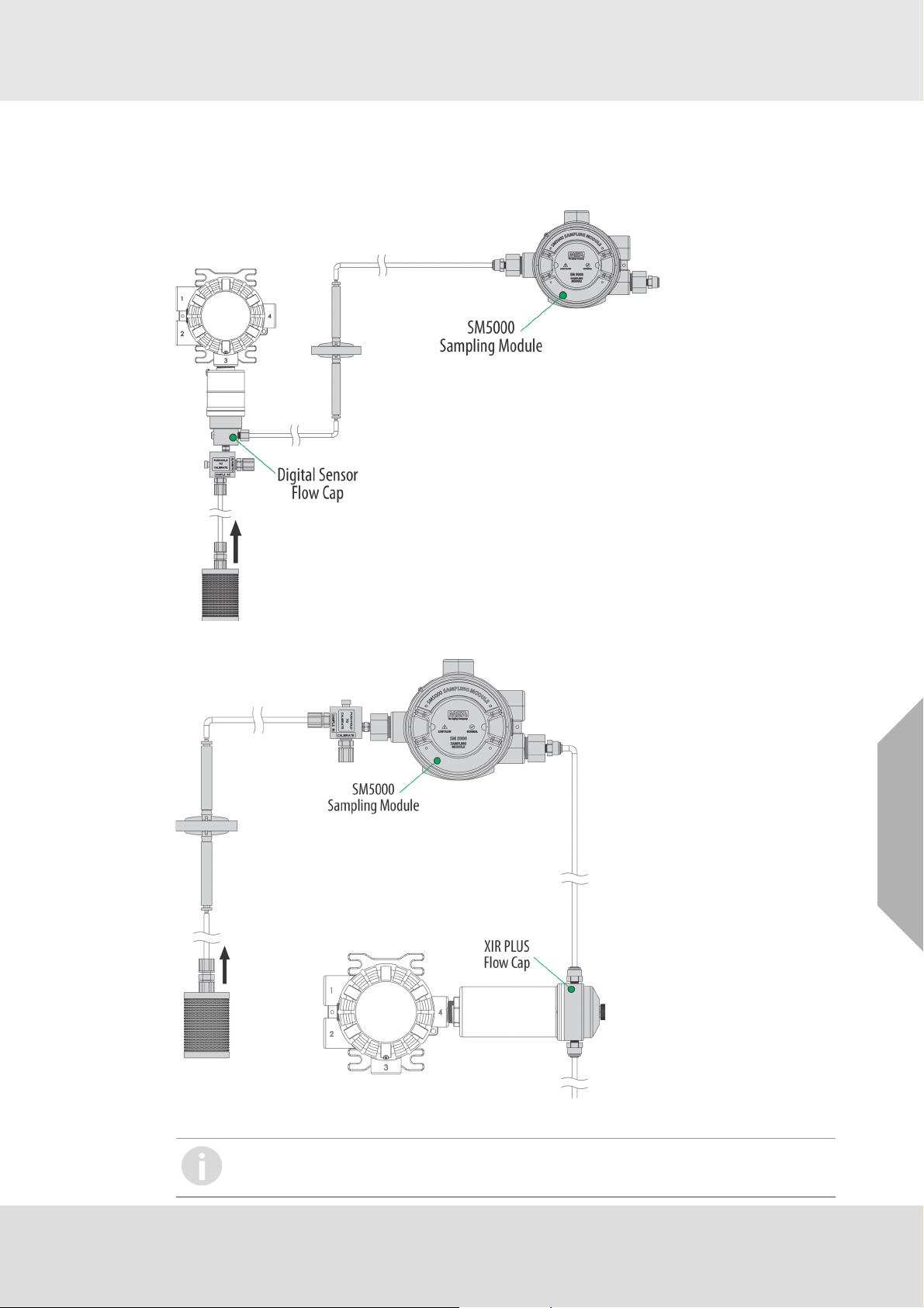
3.4.11Mounting with an SM5000 Sampling Module
An aspirated (PN 10058101) and a DC pump (PN 10043264) model are available for use with the
X5000 with either digital or XIR sensors. For more information on mounting requirements and use
with SM5000 sampling modules, see the SM5000 operating manual(s).
Installation
Fig. 24 Mounting the SM5000 with Digital Sensor
US
Fig. 25 Mounting the SM5000 with XIR PLUS Sensor
SM5000 is not for sale in EU.
Diffusion Supervision must be disabled when using the SM5000
ULTIMA® X5000
25
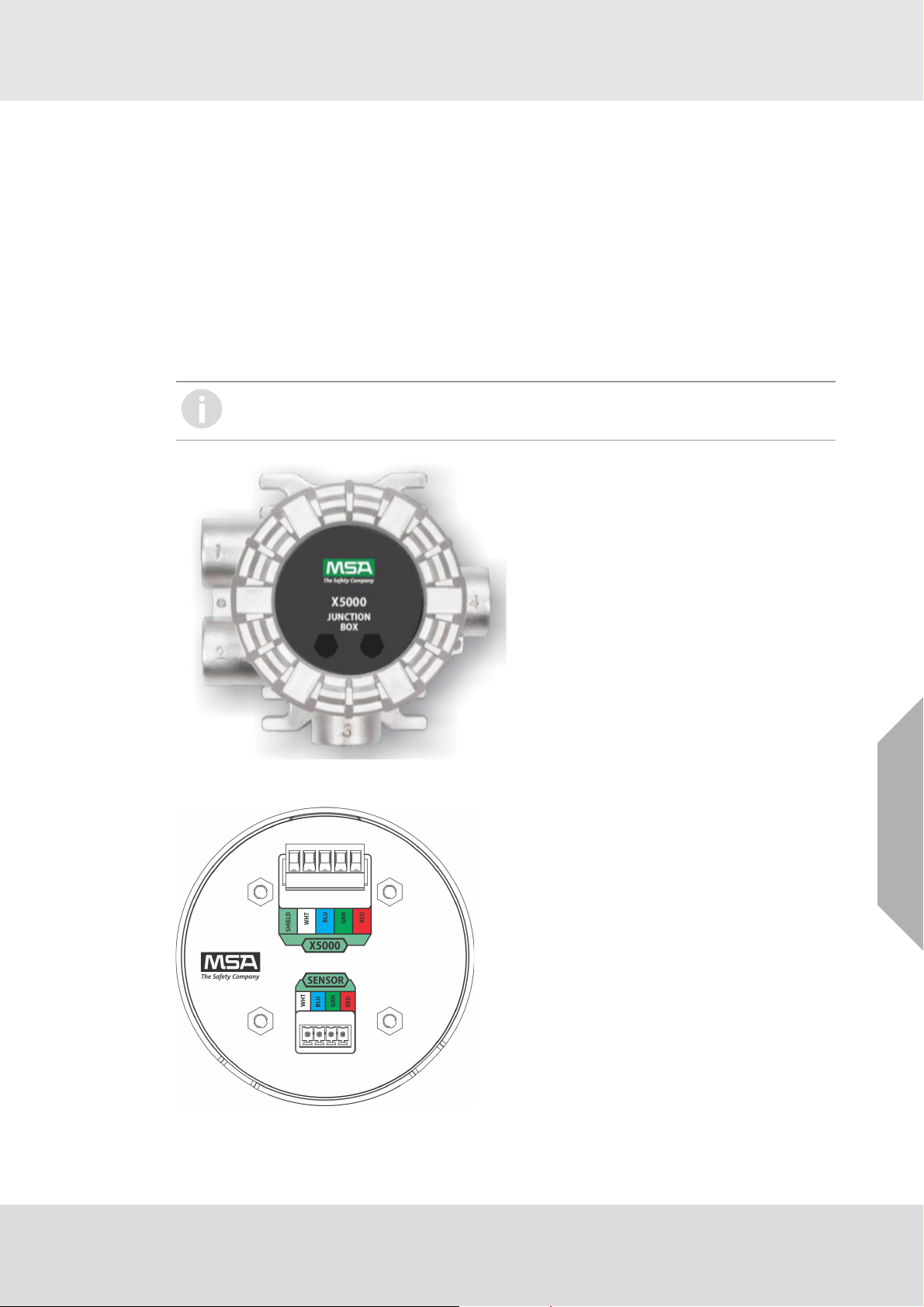
3.5 Installing a Remote Sensor Junction Box
Sensors mounted remotely must use the ULTIMA X5000 junction box. Only one sensor can be
connected to each junction box. The junction box housing is the same construction as the
ULTIMA X5000 transmitter. The mounting options and instructions for connecting the sensor are
the same for sensors connected directly to the ULTIMA X5000 transmitter housing. The junction
box is available in 316 Stainless Steel.
Sensors can be remoted up to 328 ft (100 m) from the transmitter housing, as long as the
ULTIMA X5000 transmitter is mounted within maximum distance from the power supply, as indicated in tables in section 3.6.4. The junction box does not have an illuminated display and has two
connectors: a single sensor input and an output connecting to the transmitter. A 16 AWG
(1.31mm
2
) 4 element cable with a braided shield should be used for the electrical connection
between the junction box and the ULTIMA X5000 transmitter. Specific cable recommendations
are Alpha wire 3248 or equivalent.
The X5000 junction box must be used for remote XIR PLUS sensors. The use of third
party junction boxes may void product warranty.
Installation
Fig. 26 Junction Box
Fig. 27 Junction Box Electrical Connections
US
ULTIMA® X5000
26

If the remote sensor is not easily accessed, it is best practice to install tubing that can be used to
apply calibration gas from the device display. Route the tubing to the ULTIMA X5000 Gas Monitor,
ensuring that there are no kinks, leaks or other obstructions. Secure this tubing near the monitor.
3.6 Electrical Power Connections
3.6.1 Electrical Warnings - Read before Connecting Power
WARNING!
Before wiring the ULTIMA X5000 transmitter, disconnect the power source supplying the trans-
mitter and ensure no hazardous atmosphere present; otherwise, electrical shock or ignition of
a hazardous atmosphere could occur.
Install wiring in accordance with the electrical code of the country in use, the local authority
having jurisdiction and these installation instructions, as applicable.
Do not make any connections to the ULTIMA X5000 main board or junction box input, output,
and relay connections while under power. Making connections under power could lead to electrical shock or ignition of a hazardous atmosphere.
ULTIMA X5000 with relays are not approved for non-incendive wiring methods. Use of non-
incendive wiring methods could lead to ignition of a hazardous atmosphere.
Ensure that water and dirt are not able to enter the unit via the wire or conduit. If the unit is
installed in a location known to be wet or damp, it is good practice to loop or bend the entry
into the unit that prevents water incursion.
The internal grounding terminal located in the base of the transmitter enclosure must be used
for equipment grounding. The external grounding terminal is only to be used as a supplemental
bonding connection where local authorities permit or require such a connection.
As part of the product certification, it was verified that optional communication functions of this
gas detection instrument while operating at the maximum transaction rate do not adversely
affect the gas detection operation and functions of the instrument. The product certification,
however, does not include or imply approval of the SafeSwap feature, communications
protocol or functions provided by the software of this instrument or of the communications
apparatus and software connected to this instrument.
Follow the warnings below when removing or replacing sensors. Reference Fig. 3 for compo-
nent overview.
- Never remove or replace a Sensor Body Assembly or an Ultima XIR Plus while under power
or when explosive hazards are present.
- Confirm that the area is free of explosive hazards before removing or replacing an XCell
Sensor under power.
- To remove an XCell Sensor, unscrew XCell Sensor three full turns, wait 10 seconds, and then
remove the XCell Sensor completely.
Installation
US
Failure to follow the above warnings can result in serious personal injury or loss of life.
3.6.2 Retrofit Applications with UltimaX
The Ultima X5000 was designed to be easily retrofitted with existing UltimaX wiring. When
replacing an existing UltimaX with the equivalent X5000 sensor technology, the following items
need to be checked in order for the X5000 to operate:
1) Wire gauge needs to be 18-14 AWG
2) Sufficient power must be supplied to the X5000 in accordance with the maximum wire lengths.
(See tables 1-6)
If these requirements are met, performance of the X5000 should meet the noise immunity standard equivalent of the UltimaX using the existing wiring; However, the installation may not meet
the latest EMC EN50270 noise immunity standard that the X5000 meets with the grounding and
wiring scheme as indicated in I/O drawing SK3015-1051.
ULTIMA® X5000
27

3.6.3 Electrical Hardware Requirements
Braided shielded, twisted pair, instrument quality wire or cable should be used to minimize the
possibility of noise interference and contact with other voltages. Selection of shielded cable must
comply with local requirements.
Conduit, in addition to braided shielded wire, may also be needed in areas where large amounts
of electrical noise is expected. All cable shields should be terminated to earth ground at one end
only.
The ULTIMA X5000’s (RED) power connector terminals can accommodate up to 14 AWG
(2.08 mm
Incoming power and signal cables should be a braided shield cable such as Alpha Wire 3248 or
equivalent. The braided shield must be terminated to the instrument housing with a 360 degree
connection to earth ground as shown in Fig. 31 or alternatively, the earth ground at the user’s
power source location.An external Class 2 power supply is required to supply 11-30 VDC to the
ULTIMA X5000. Incoming power and signal cables should be a braided shield cable such as
Alpha Wire 3248 or equivalent.
2
). Four conductors are also required for the ULTIMA X5000 remote junction boxes.
Installation
ULTIMA® X5000
US
28
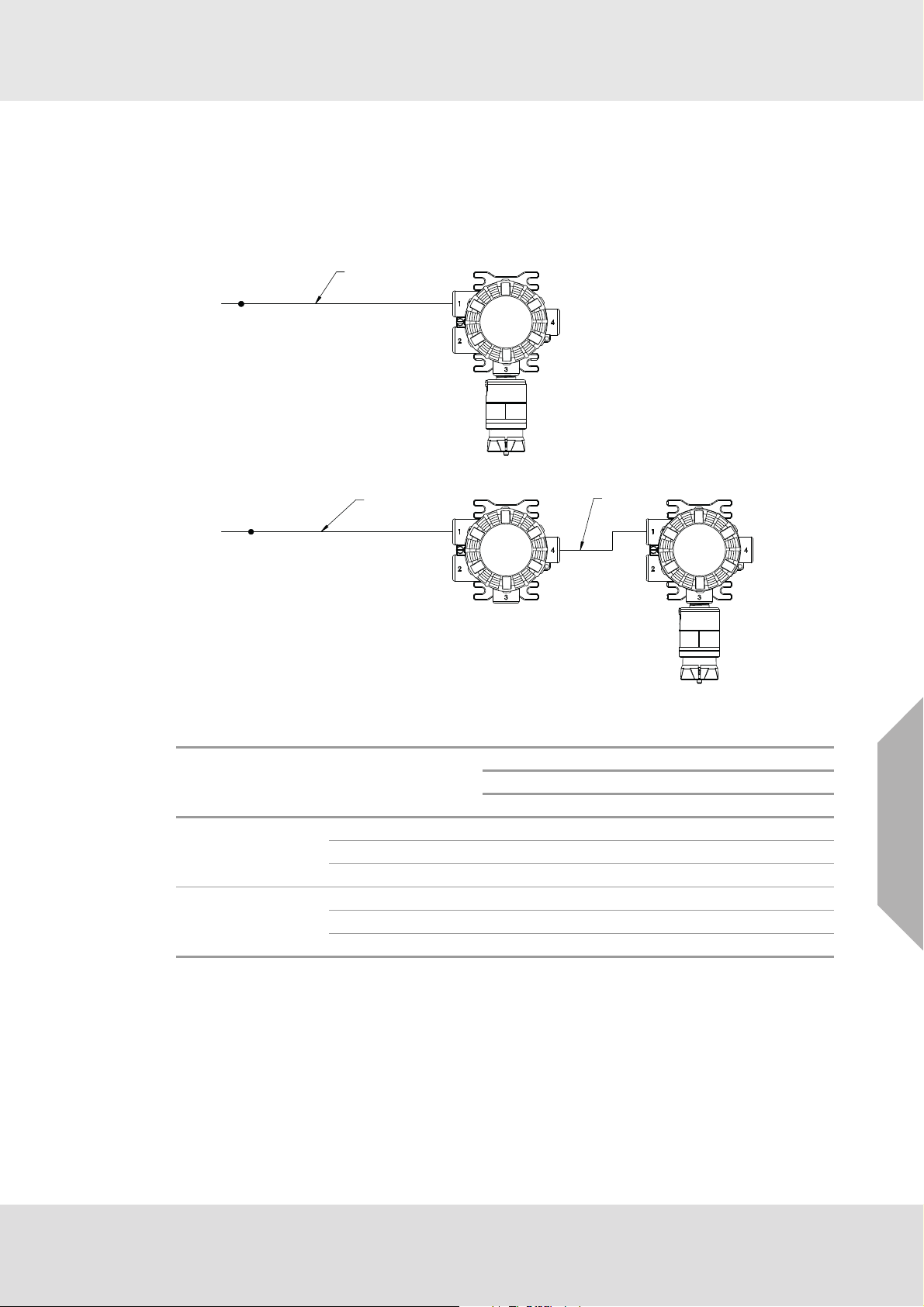
3.6.4 Power Load Requirements and Maximum Mounting Distances
Consider future needs when selecting cable size and power supply. The maximum distance
between the X5000 transmitter and the power supply depends on the sensor configuration
(sensing technology and one or two sensors), wire gauge, and the power supply voltage.The
tables below outline the maximum transmitter mounting distances. First determine if the sensor(s)
will be locally or remotely mounted. Then choose sensor type(s). The corresponding nominal
maximum power and mounting distances by wire gauge are shown.
SEE TABLE 1 & 2
24V DC
X5000
SENSOR 1
Installation
SEE TABLE 1 & 2
24V DC
Fig. 28 Single Sensor
Sensor Mounting Sensor 1
Echem 2.8 2211 3337 5314 8440
Mounted on transmitter
Catalytic 4.9 1548 2335 3719 5907
XIR PLUS 6.7 1184 1787 2846 4520
Remote mounted on
junction box (up to
328 ft)
Echem 2.8 2210 3335 5313 8439
Catalytic 4.9 1504 2294 3679 5867
XIR PLUS 6.7 1090 1697 2759 4435
Max.
Power
(W)
328 ft
MAX
X5000
JUNCTION
BOX
SENSOR 1
Max. Distance (ft) to transmitter
1
24 VDC Supply
18 AWG 16 AWG 14 AWG 12 AWG
US
Tab. 1 Maximum Wire Length to Main Transmitter with Single Sensor, Imperial Units
1
When sizing a system's 24 V supply, a 1 A inrush current with a 1 ms duration should be
considered for each ULTIMA X5000 on the power supply.
Assumes transmitter was ordered with relays
ULTIMA® X5000
29

Installation
Max. Distance in meters
24 VDC Supply
2
1mm21.5 mm22.5 mm24mm
Sensor Mounting Sensor 1
Max.
Power
(W)
1
0.75 mm
Echem 2.8 597 796 1195 1989 3066
Mounted on transmitter
Catalytic 4.9 417 557 836 1392 2146
XIR PLUS 6.7 319 426 640 1065 1642
Remote mounted on
junction box (up to
100 m)
Echem 2.8 596 795 1194 1988 3065
Catalytic 4.9 404 544 823 1380 2134
XIR PLUS 6.7 290 398 613 1039 1616
Tab. 2 Maximum Wire Length to Main Transmitter with Single Sensor, Metric Units
1
When sizing a system's 24 V supply, a 1 A inrush current with a 1 ms duration should be
considered for each ULTIMA X5000 on the power supply.
Assumes transmitter was ordered with relays
2
ULTIMA® X5000
US
30

Installation
SENSOR 2
SENSOR 2
X5000
X5000
JUNCTION
BOX
SENSOR 1
SENSOR 1
328 ft
MAX
24V DC
24V DC
SEE TABLE 3 & 4
SEE TABLE 3 & 4
Fig. 29 Two Sensors
Sensor
Mounting
Two
sensors
mounted
on transmitter
One
sensor
mounted
on junction box
(100 m
max), one
sensor on
transmitter
Tab. 3 Maximum Wire Length to Main Transmitter with Two Sensors, Imperial Units
1
Max. Distance (ft) to transmitter
24 VDC Supply
Sensor 1 Sensor 2
Max.
Power
(W)
1
18 AWG 16 AWG 14 AWG 12 AWG
Echem 3.6 2078 3136 4994 7932
Echem
Catalytic 5.3 1473 2223 3541 5623
XIR PLUS 7.0 1076 1623 2585 4106
Echem 5.3 1473 2223 3541 5623
Catalytic
Catalytic 10.6 1151 1736 2765 4392
XIR PLUS 10.9 893 1347 2146 3408
Echem 7.0 1076 1623 2585 4106
XIR PLUS
Catalytic 10.9 893 1347 2146 3408
XIR PLUS 11.6
* One sensor must be remote mounted if using two
XIR PLUS sensors
Echem 3.6 2096 3154 5012 7952
Echem
Catalytic 5.3 1441 2193 3512 5596
XIR PLUS 7.0 982 1536 2501 4024
Catalytic
Echem 5.3 1441 2193 3512 5596
Catalytic 10.6 1124 1711 2741 4368
XIR PLUS 10.9 763 1225 2029 3295
Echem 7.0 982 1536 2501 4024
XIR PLUS
Catalytic 10.9 763 1225 2029 3295
XIR PLUS 11.6 731 1135 1843 2961
When sizing a system's 24 V supply, a 1 A inrush current with a 1 ms duration should be
considered for each ULTIMA X5000 on the power supply.
Assumes transmitter was ordered with relays
US
ULTIMA® X5000
31

Installation
Sensor
Mounting
Two
sensors
mounted
on transmitter
One
sensor
mounted
on junction box
(328 ft
max), one
sensor on
transmitter
Sensor 1 Sensor 2
Echem 3.6 561 748 1123 1869 2882
Echem
Catalytic 5.3 397 530 796 1325 2043
XIR PLUS 7.0 290 387 581 968 1491
Echem 5.3 397 530 796 1325 2043
Catalytic
Catalytic 10.6 310 414 622 1035 1596
XIR PLUS 10.9 241 321 482 803 1238
Echem 7.0 290 387 581 968 1491
XIR PLUS
Catalytic 10.9 241 321 482 803 1238
XIR PLUS 11.6 213 284 428 711 1096
Echem 3.6 566 753 1128 1875 2887
Echem
Catalytic 5.3 387 521 787 1316 2034
XIR PLUS 7.0 261 359 555 942 1467
Echem 5.3 387 521 787 1316 2034
Catalytic
Catalytic 10.6 302 406 614 1028 1588
XIR PLUS 10.9 200 283 446 768 1204
Echem 7.0 261 359 555 942 1467
XIR PLUS
Catalytic 10.9 200 283 446 768 1204
XIR PLUS 11.6 195 266 409 694 1079
Max.
Power
(W)
1
0.75 mm
Max. Distance in meters
24 VDC Supply
2
1mm21.5 mm22.5 mm24mm
2
Tab. 4 Maximum Wire Length to Main Transmitter with Two Sensors, Metric Units
1
When sizing a system's 24 V supply, a 1 A inrush current with a 1 ms duration should be
considered for each ULTIMA X5000 on the power supply.
Assumes transmitter was ordered with relays
With dual sensors, and only one remoted at max length, add 6 m from the dual remoted sensor
calculation.
US
ULTIMA® X5000
32

Fig. 30 Two Remoted Sensors
SEE TABLE 5 & 6
X5000
SENSOR 1
SENSOR 2
JUNCTION
BOX
JUNCTION
BOX
328 ft
MAX
24V DC
Installation
Sensor
Mounting
Sensor 1 Sensor 2
Max.
Power
(W)
1
18 AWG 16 AWG 14 AWG 12 AWG
Max. Distance (ft) to transmitter
24 VDC Supply
Echem 3.6 2079 3134 4992 7932
Two
sensors
mounted
on junction box
up to
328 ft
for24V
Echem
Catalytic
XIR PLUS
Catalytic 5.3 1421 2173 3492 5576
XIR PLUS 7.0 962 1516 2481 4004
Echem 5.3 1421 2173 3492 5576
Catalytic 10.6 1104 1691 2721 4348
XIR PLUS 10.9 743 1205 2009 3275
Echem 7.0 962 1516 2481 4004
Catalytic 10.9 743 1205 2009 3275
XIR PLUS 11.6 711 1115 1823 2941
Tab. 5 Maximum Wire Length to Main Transmitter with Two Remoted Sensors, Imperial Units
1
When sizing a system's 24 V supply, a 1 A inrush current with a 1 ms duration should be
considered for each ULTIMA X5000 on the power supply.
Assumes transmitter was ordered with relays
Sensor
Mounting
Sensor 1 Sensor 2
Max.
Power
(W)
1
0.75 mm
Max. Distance in meters
24 VDC Supply
2
1mm21.5 mm22.5 mm24mm
2
Echem 3.6 560 747 1122 1869 2881
Two
sensors
mounted
on junction box
up to
100 m
Echem
Catalytic
XIR PLUS
Catalytic 5.3 381 515 781 1310 2028
XIR PLUS 7.0 255 353 549 936 1461
Echem 5.3 381 515 781 1310 2028
Catalytic 10.6 296 400 608 1022 1582
XIR PLUS 10.9 194 277 440 762 1198
Echem 7.0 255 353 549 936 1461
Catalytic 10.9 194 277 440 762 1198
XIR PLUS 11.6 189 260 403 688 1073
US
Tab. 6 Maximum Wire Length to Main Transmitter with Two Remoted Sensors, Metric Units
1
When sizing a system's 24 V supply, a 1 A inrush current with a 1 ms duration should be
considered for each ULTIMA X5000 on the power supply.
Assumes transmitter was ordered with relays
ULTIMA® X5000
33

3.6.5 Instructions for Power and Analog Output
WARNING!
Read all electrical warnings and wiring requirements before connecting power to the
ULTIMA X5000.
Failure to follow the above warning can result in serious personal injury or loss of life.
The red colored (4-pin) connector interfaces power and analog outputs 1 and 2. The HART interface is a separate, green colored (2-pin) connector.
The green colored (4-pin) connectors interface sensors one and two.
Using shielded cable is recommended. The cable shield should be terminated internal to the
instrument enclosure using the crimp terminal provided (see Fig. 32).
(1) Remove the ULTIMA X5000 cover by turning counter-clockwise.
(2) Pull on the metal bail, removing electronics, to expose sensor and power connections.
(3) Remove the red colored power connector.
(4) Use a small, flat head screw driver to open wire entries on the connector.
(5) Strip cable jacket to expose shield and the four individual wires.
Installation
(6) Connect the power and analog output wires. Wire locations are marked on the cover plate
(see Fig. 31):
a. +DC
b. -DC
c. mA1 - analog output of sensor 1
d. mA2 - analog output of sensor 2
Fig. 31 Power, HART, and Sensor Inputs
(7) Tighten screws on connector and tug gently on wires to ensure they are secure.
US
(8) Connect shield of cable to base of instrument housing (see Fig. 32).
ULTIMA® X5000
34

Installation
Fig. 32 Connecting Power and Grounding Cable
(9) Attach the connector to the board stack, making sure the appropriate wires are in the correct
terminals.
(10) Connect HART wires (for optional local HART port).
(11) Connect an XCell or XIR PLUS sensor using the green connector. Sensor wires are already
connected as shown on the cover plate (see Fig. 33):
a. +DC (RED)
b. RS485 Com + (GRN)
c. RS485 Com - (BLU)
d. -DC (WHT)
US
Fig. 33 Connecting a Sensor to the Board
Note: Sensor connectors come pre-wired on the sensor body.
Note: Leaving exposed wire from the connector can electrically short the system.
ULTIMA® X5000
35

Installation
(12) Replace the board stack by aligning the four metal standoffs with the four holes inside the
ULTIMA X5000housing. Push firmly on the board stack where indicated (see Fig. 34).
Fig. 34 Highlighted Areas Show Where to Press when Replacing a Board Stack
NOTICE
Ensure that the electronics assembly is fully engaged in the mounting holes. If not fully seated,
the touch interface performance can be negatively affected
NOTICE
Avoid pressing on the left and right areas where the LEDs are located. Pressing directly on the
display will damage the display and will void the warranty.
Care must be taken to insure the X5000 inside glass surface is free of smudges/dirt and grease.
Dirt and grease can interfere with the touch interface of the display.
ULTIMA X5000 Installation Outline Drawings
Model Document No.
ULTIMA X5000 SK3015-1051
Tab. 7 Installation Outline Drawings
3.6.6 Relay and Power Connections Relay Board Stack Overview
The ULTIMA X5000 can be purchased with three relays. Two of the relays can be configured for
either de-energized (default) or energized and latching or non-latching (default). The third relay is
a dedicated fault relay.
All electrical connections to internal relays can be made directly on the PC board. The board is
labeled for Normally Open (NO) and Normally Closed (NC) de-energized state.
US
ULTIMA® X5000
36

Fig. 35 PC Board with Relays
Installation
Fig. 36 Non-Relay Board Stack Fig. 37 Relay Board Stack
Relay Specifications
Relays SPDT (Single Pole Double Throw)
Fault Normally Energized
Warning Configurable
Alarm Configurable
Relay Rating
125 or 250 VAC (Resistive)
30 VDC (Resistive) 5A
Tab. 8 Relay Specifications
If using AC power, the relay wires should not be run within the same conduit or cable tray as the
DC power supplied to the ULTIMA X5000 or the ULTIMA X5000 junction box connection. A separate wire entry on the device should be used for AC power connected to the relays. The
ULTIMA X5000 is built with an additional wire entry to allow this.
Exceeding the volt-amp rating of the relay can cause damage to the switching contacts.
5A, 100K Cycles
1.6 HP @ 250 VAC
US
ULTIMA® X5000
37

Installation
WARNING!
ULTIMA X5000 with relays is not approved for Division 2 or Zone 2 wiring methods. Use of
Division 2 or Zone 2 wiring methods could lead to ignition of a hazardous atmosphere.
Failure to follow the above warning can result in serious personal injury or loss of life.
Relay Connections to Inductive Loads
If connecting the relays to motors, fluorescent lighting, or other inductive loads, it is necessary to
suppress any sparks or inductive feedback that may occur at the relay contact. These effects may
render the unit inoperative.
One way to reduce these effects is to install a Quencharc
being switched.
Fault Relay Wiring and Configurations
The Fault relay state in non-fault operating condition is Energized and terminal connections are
supplied for Normally Closed and Normally Open.
The energized fault relay setting provides an electrical path for fail-safe relay operation. In the
event of any failure, including loss of power, the relay will change to the de-energized state to
indicate a fault condition.
The Fault relay state cannot be reconfigured.
Relay Energy State and Terminal Connections
The ULTIMA X5000 relays can be selected as energized or de-energized on the device. The
default configuration is the De- Energized state. The preferred relay energy state should be determined before making connections. Tab. 9 shows the terminal connections by energy state and is
applicable to both relay 1 and relay 2.
®
(Part Number 630413) across the load
Energy State NC (Normally Closed) NO (Normally Open)
De-Energized (default) Closed Open
Energized Open Closed
Tab. 9 Relay Terminal Connections by Energy State
US
ULTIMA® X5000
38

4 Operation
WARNING!
Refer to manual addendum (Part Number 10182779) for Certification Information and additional
safety information before installation and operation.
Failure to follow the above warning can result in serious personal injury or loss of life.
The ULTIMA X5000 Series transmitter is factory calibrated and shipped with the most common
default options to minimize set up effort. Any of the default settings can be changed to meet the
user’s individual needs via the EZ touch buttons on the display of the ULTIMA X5000.
4.1 Startup
4.1.1 Initial Startup
The first time the ULTIMA X5000 is powered on, the analog output goes to the Maintenance Mode
setting (default 3.5 mA) and the following will appear on the display while the LEDs cycle from
GREEN, to RED, to AMBER, then to GREEN:
• ULTIMA X5000 Logo with Software Version No.
• Tachometer countdown
• MSA Logo
XCell oxygen and carbon monoxide (CO) sensors require a 30 minute start-up time before being
fully functional. During this time the analog output signal will be at its maintenance (3.5 mA) level
while the display indicates the 30 minute countdown. All other XCell sensors have a 2 minute
countdown time during which the analog output signal will be at its maintenance (3.5 mA) level.
A full calibration is recommended after one hour of a sensor being installed and acclimated to the
environmental conditions. See section 5 for calibration details.
4.1.2 Sensor Warm Up Times
Operation
WARNING!
For optimal sensor performance, allow sensors 24 hours to acclimate to application conditions
before performing an initial calibration.
Failure to follow the above warning can result in serious personal injury or loss of life.
XIR PLUS: ≤ 5 min
H
S: ≤ 5 min
2
: ≤ 5 min
SO
2
Cl
: ≤ 10 min
2
NH
: ≤ 5 min
3
Cat Bead: ≤ 5 min
CO: 30 min (see table below)
O
: 30 min
2
Carbon Monoxide sensor gas codes 10, 11, 12, and 14 may require initial warm-up periods longer
than 30 minutes. If the 30-minute warm up is over, the sensor may show a positive reading that
exceeds alarm levels. In the event of a short-term power outage, the warm-up time for carbon
monoxide gas codes 10, 11, 12, and 14 will be significantly less. See the table below to estimate
required warm-up time.
Reading Level < 10ppm
1
< 1ppm
Time left unpowered Time to warm up
1 min ≤ 5 min ≤ 5min
8 hours ≤ 30 min ≤ 30 min
5 days ≤ 30 min 2-4 hrs
1 month ≤ 2 hrs 6-10 hrs
US
Tab. 10 Warm Up Times CO
1
The minimum alarm level of all three CO senors is 10ppm. Below this level would not cause an
alarm on the device.
ULTIMA® X5000
39

4.2 Settings
The ULTIMA X5000 is a tool free transmitter. The two EZ touch buttons on the face of the display
can be used to navigate through the menu structure. The buttons are designed for use with fingers
with a “press” and “release” action, and work best without gloves.
Button Function
left button (↓) scrolling through each menu
right button (→) selecting a particular menu option
Tab. 11 Navigating through the menu structure
Changing a value
(1) Select the relevant option with →.
The arrow disappears and the first digit to change appears underlined.
(2) Scroll through the numbers with ↓.
(3) Use → to move on to the next digit.
When the arrow reappears, the value changing is finished.
When entering a new value, remember the following to ensure settings are saved:
•Use SAVE before exiting or settings will be lost.
•Use BACK to go back to previous screen.
•Use CANCEL to go back to main settings menu (i.e. BACK).
•Use HOME to return to gas reading display.
Operation
ULTIMA® X5000
US
40

4.2.1 Instrument Settings
The following settings are saved to the device memory and will not change if the sensor type is
changed.
(1) Scroll to Settings.
(2) Select Instrument.
(3) Select to enter the menu.
Setting Default Menu 1 Options Menu 2 Options
Relay Setup
Relay State De-energized
(Fault Relay
Relay 1
Relay 2
De-energized
Energized
always energized)
Mapping Common Relay 1
Relay 2
Common
Discrete
Horn
Analog Settings
(see Tab. 13)
Custom 1
(see Tab. 13)
3.5mA with HART
1.25mA with HART
Custom 1
Custom 2
Custom Settings
Calibration
Cleaning mode
Fault
Maintenance
Operation
1
Cal Alert Disabled
Enable
Disable
Bluetooth Enabled Bluetooth Status
Reset All
Min/Max/Avg 1h
Interval (1h, 8h, 24h)
Start Hour (0-23h)
Swap Delay Enabled
Enable
Disable
Set Date
Password
UTC-5
(Factory Date and
Time)
Disabled 0000-9999,
Year (2000-2999)
Month (Jan-Dec)
Day (0-31)
Time (0:00-23:59)
incr. 0001
Controller Data Reset N/A Controller Data Reset
Display Units
Sensor Dependent
(see Tab. 14)
PPM
mg/m
µMol
3
%Vol
Tag #
Blank Only configurable via
HART and Bluetooth
Reset Main Unit N/A Reset Main Unit
(none)
Enable
Disable
Reset All
US
Tab. 12 Default Device Settings
1
Cleaning mode not available
ULTIMA® X5000
41

Operation
Setup Relay State for Energized or De-Energized
Relays 1 and 2 are default De-energized. Relay 3 is a fault relay that is set to Energized and
cannot be changed.
To set Alarm Relay State:
(1) Scroll to Settings.
(2) Select Instrument.
(3) Select Relay Setup.
(4) Select Relay State.
(5) Select Relay 1 or Relay 2.
(6) Select Energized or De-Energized.
Relay Mapping
Relay 1 and Relay 2 can be configured for common, discrete, and horn modes via the device
display menu or X/S Connect app.
Common mode is the default relay mapping setting. In Common mode, Relay 1 is actuated by
Alarm 1 on either sensor, and Relay 2 is actuated by Alarm 2 on either sensor.
Fig. 38 Common Mode Relay Map and Alarm Actuation
Discrete mode allows a separate action for each sensor. Relay 1 is actuated by Sensor 1 alarms
and Relay 2 is actuated by Sensor 2 alarms.
Fig. 39 Discrete Mode Relay Map and Alarm Actuation
US
ULTIMA® X5000
42

Operation
Horn mode is designed to allow local acknowledgment of a relay-triggered horn, while the alarm
state is still present. All alarms on both sensors trigger both relays, however the second relay can
be acknowledged by pressing one finger over each of the EZ touch buttons and holding for 1
second before releasing.
Fig. 40 Horn Mode Relay Map and Alarm Actuation
Analog Output Settings for Fault Conditions
Analog outputs can be set to 3.5 mA and 1.25 mA with HART, or to custom output values as listed
in Tab. 13. Output settings for oxygen sensors are not configurable. The Maintenance analog
output is used during start up, Reset Main Unit, and Controller Data Reset.
To change Analog outputs settings:
(1) Scroll to Settings.
(2) Select Instruments.
(3) Scroll and Select Analog Settings.
(4) Select 3.5, 1.25, Custom 1 or Custom 2.
(5) Select Save.
(6) (Only Custom) Select Fault, Calibration, or Maintenance.
(7) (Only Custom) Enter desired output levels (options in Tab. 13).
(8) (Only Custom) Select Save.
(9) (Only Custom) Repeat for remaining outputs.
(10) Select Save.
US
ULTIMA® X5000
43

Operation
Output
Setting (mA)
Fault 3.5
Calibration
(excl. O
)
2
Cleaning Mode
(NOT
3.5 mA 1.25 mA
3.5
3.5
2
2
2
1.25
1.5
2.0
2
2
2
ENABLED)
Maintenance 3.5
O
Calibration 3.5
2
2
2
3.5
1.5
2
2
Cal Alert 3.5 3.0 3.0 3.0
Zero Reading 4.04
Over Range 21.7
2
2
Custom 1
Default
1
Custom 2
Default
2.0 2.0
3.0 3.0
2.5 2.5
3.5 3.5
21.7
3
Same as
Calibration
AO Range Options
Range: 0.000-3.750
Increment: 0.025
Range: 0.000-3.750
Increment: 0.025
Range: 0.000-3.750
Increment: 0.025
Range: 0.000-3.750
Increment: 0.025
Range: 0.000-3.750
Increment: 0.025
Range: 0.000-3.750
Increment 0.025
Tab. 13 Analog Output Setting Options
1
Default factory setting
2
Not configurable
3
For an O2 sensor, 21.7 mA is the default Custom 1 setting and is not configurable.
Calibration Alert
Sensors with TruCal technology actively monitor sensor and adjust sensitivity without any manual
intervention. When equipped with Diffusion Supervision, TruCal will also monitor the sensor inlet
for obstructions while Diffusion Supervision is enabled. These sensors do not need to be calibrated on a static maintenance cycle. When a manual calibration is recommended, the sensor will
detect this and slow flash either the left green LED or right green LED indicating that calibration is
recommended for sensor 1 or sensor 2 respectively. Users can also enable Calibration Alert so
that an analog output signal is sent to the control room when a calibration is recommended.
Whether or not the calibration alert is enabled, if gas is detected by the sensor, the
ULTIMA X5000's analog output and display will follow the gas reading.
WARNING!
XCell Sensors with TruCal (CO & H
S) with Calibration Alert enabled provide an indication for
2
“Calibration Recommended” and “Calibration Required”. When either indication is provided by the
device, calibrate the sensor.
Failure to follow the above warning can result in serious personal injury or death.
To Enable Calibration Alert:
(1) Scroll to Settings.
(2) Select Instrument.
(3) Scroll and select Cal Alert.
(4) Select Enable Cal Alert.
(5) Scroll and select Save.
ULTIMA® X5000
US
44

Operation
Enable Bluetooth Communications
Every ULTIMA X5000 ordered with Bluetooth comes with the communications enabled by default.
Bluetooth must be enabled for any Bluetooth functions to operate. A compatible Bluetooth host
with the X/S Connect app is needed for connection.
To disable Bluetooth:
(1) Scroll to Settings.
(2) Select Instrument.
(3) Scroll and select Bluetooth.
(4) Select Bluetooth Status.
(5) Select Disable.
(6) Select Save.
Devices ordered without Bluetooth do not contain a Bluetooth chip, but may show Bluetooth as a menu option. On these devices if a user tries to enable Bluetooth, it will
appear as though the enable setting is not being saved. Check the product configuration. If the third value is a non-zero value, it may be ordered without Bluetooth.
Bluetooth Pairing
The instrument memory has the ability to store up to 25 mobile devices in its memory.
As a visual indication, the green LEDs will toggle and quickly flash when a device is paired.
Once paired with an X5000, the user will be able to connect to the same X5000 remotely and
without needing to enter a pairing code, unless over 25 other devices are paired with the same
X5000 afterwards.
To pair with the X5000:
(1) Download the X/S Connect App from the Google Play Store or the iOS App Store.
(2) Open the X/S Connect App.
(3) Select “Connect” for the X5000 that you would like to connect with.
(4) (First Time Only) When prompted, tap EZ touch button to display a 6-digit pass code.
(5) Enter Pairing Code shown on X5000 display.
Bluetooth Security
The Bluetooth connection is encrypted and secured with a unique six digit pin that must be
confirmed on the mobile device and acknowledged on the detector display. All of the previously
paired devices can be erased from the X5000 to provide additional security and control.
To Reset All device pairings:
(1) Scroll to Settings.
(2) Select Instrument.
US
(3) Scroll and select Bluetooth.
(4) Scroll and select Reset All.
(5) Select Continue.
NOTICE
Reset All will delete all paired device memory. All devices will have to re-initiate pairing at the
device.
Bluetooth Tag ID
See section 4.3 to view Bluetooth Tag ID.
ULTIMA® X5000
45

Operation
Min/Max/Average
The minimum, maximum, and average gas readings can be set for a user-defined interval. For
example, if the interval is set to 24 and the start hour is set to 6, the Min/Max/Avg values will
update every 24 hour period starting at 6 am.
The default interval is set to 1h and start hour is 0. The Interval and Start Hour are driven by the
Time and Date of the transmitter.
To change Min/Max/Average interval and time:
(1) Scroll to Settings.
(2) Select Instrument.
(3) Scroll and select Min/Max/Average.
(4) Select Set Interval.
(5) Enter Interval (1h, 8h, 24h) and Save.
(6) Scroll to Set Start Hour.
(7) Enter Start Hour (0-24h) and Save.
The Min/Max/Average values are only viewable through the X/S connect app or HART.
Swap Delay
Swap Delay allows the user a brief window to change an XCell sensor without the device going
into a fault condition. Once a sensor is disconnected from the transmitter, the user will have
2 minutes to reconnect a sensor. During this time, the device analog output will go to its Maintenance level. If a sensor is reconnected or replaced during the 2 minute window, the new sensor’s
countdown sequence will begin and the analog output will remain at the Maintenance level. After
the sensor countdown is complete, the analog output will return to reporting a live gas reading. If
a sensor is not reconnected after the 2 minute window, the ULTIMA X5000 will enter a “Sensor
Missing” fault condition. All XCell Sensors have SafeSwap and do not need to be disconnected
from power while changing sensors. For more details on how to change sensors, see section 6.2.
Swap Delay is enabled on all ULTIMA X5000 transmitters by default.
NOTICE
The transition to maintenance mode during the 2 minute Swap Delay window and sensor countdown will not trigger the Fault Relay. The Fault Relay will only be triggered when the device enters
a fault condition.
To enable or disable Swap Delay:
(1) Scroll to Settings.
(2) Select Instrument.
US
(3) Scroll and select Swap Delay.
(4) Select Enabled or Disabled.
(5) Select Save.
ULTIMA® X5000
46

Operation
Time and Date Setup
Time and date are set at the factory in GMT. When selected, the current date is displayed. Select
Change to edit date and time. The user must save to move onto the next date setting. The Min/
Max/Average settings are driven by the date and time and should be changed to local time for data
accuracy.
To change Time and Date:
(1) Scroll to Settings.
(2) Select Instrument.
(3) Scroll and select Set Date.
(4) Scroll and Select Change.
(5) Select Year and Save.
(6) Select Month and Save.
(7) Select Day and Save.
(8) Set Time and Save.
You can also use the X/S connect app to sync time and date with a mobile device.
Enable Password
Enabling password will require the user to enter the password before entering any of the settings
menu. The password entry screen defaults to 0000 and is disabled by default.
When the password is enabled, a lock icon will appear in the top right corner of the display.
If the password is lost, call MSA Customer Service at 1-800-672-2222.
To enable the password:
(1) Scroll to Settings.
(2) Select Instrument.
(3) Scroll and select Password.
(4) Select Enable Password.
(5) Scroll and select Save.
(6) Confirm the Password (password is default 0000 until changed).
Change Password
A password can be changed whether or not the password is enabled.
If the password is lost, call MSA Customer Service at 1-800-672-2222.
To change the password:
(1) Scroll to Settings.
US
(2) Select Instrument.
(3) Scroll and select Password.
(4) Select Change Password.
(5) Enter desired password.
(6) Select Save.
(7) Scroll and select Save to confirm password.
ULTIMA® X5000
47

Operation
Language
The X5000 main display can be viewed in multiple languages. Available Languages are: English,
French, Spanish, Portuguese, Italian, Dutch, Russian, Chinese, and German.
The X/S Connect App is only available in English, and does not change when the display language
on the ULTIMA X5000 is changed.
To change the display language:
(1) Scroll to Settings.
(2) Select Instrument.
(3) Scroll and select Language.
(4) Select English, French, Spanish, Portuguese, Italian, Dutch, Russian, Chinese, or German.
(5) Scroll and select Save.
Controller Data Reset
Controller Data Reset will reset all of the settings in the main PCBA to their factory defaults and
cycle power to the unit.
To reset data to factory default values:
(1) Scroll to Settings.
(2) Select Instrument.
(3) Scroll and select Controller Data Reset.
(4) Select Continue.
The unit will reboot, and the analog output will go to the values entered for Maintenance.
Display Units
The default display units are dependent on the sensor type. See Tab 9 for default sensor units.
Only % LEL is available for combustible sensors. Only % is available for oxygen sensors.
To change display units:
(1) Scroll to Settings.
(2) Select Instrument.
(3) Scroll and select Units.
(4) Select PPM, mg/m
(5) Scroll and select Save.
Tag Number
Displays current tag. Default is blank. Below are the valid characters one can enter to identify their
unit. Entering the tag is only available via the X/S Connect App and HART. When changed, this
will be the name used by the transmitter for advertising Bluetooth signal.
3
or μMol.
US
Fig. 41 Valid Characters
ULTIMA® X5000
48

Reset Main Unit
Reset Main Unit will cycle power on the instrument, without changing any of the settings.
To reset the main unit:
(1) Scroll to Settings.
(2) Select Instrument.
(3) Scroll and select Reset Unit.
(4) Select Continue.
The unit will reboot, and the AO will go to the values entered for Maintenance.
4.2.2 Sensor Settings
The following settings are saved to the ULTIMA X5000 so that if the sensor is replaced with the
same sensor type (gas and range), the settings will remain the same. If a different sensor type
and range is used to replace the previous sensor, the new sensor’s default settings will upload to
the device.
To change sensor settings:
(1) Scroll to Settings and select it.
(2) Select Sensor.
Operation
(3) Select an option to enter the menu.
Alarm Set Points
There are two configurable alarm set points for each sensor. Alarm set point maxima are limited
to the full scale range of the sensor. Alarm minima are listed in Tab. 14.
To change alarm set points:
(1) Scroll to Settings and select it.
(2) Select Sensor.
(3) Select Alarm Setup.
(4) Select Alarm Set Points.
(5) Enter desired alarm set point (this will be limited by sensor range).
(6) Scroll and select Save.
US
ULTIMA® X5000
49

Operation
Alarm Actions
Relays can be triggered by an alarm threshold as gas readings increase or decrease. Most applications require increasing alarm thresholds, except for Oxygen monitoring, which is most often a
decreasing alarm.
Relays can also be triggered such that the relays are latched in the alarm state until a user
acknowledges the alarm by placing one finger over each of the EZ touch buttons and holding for
1 second before releasing. If the alarm relay is configured to be Non-Latching, the alarm relay
output must be connected to an auxiliary device that performs the latching function. When the
alarm relay state is chosen to be Non-Latching, the relay will reset once the alarm condition (gas
value) returns to a value outside of the alarming condition.
A user can also disable alarms in the Alarm Actions menu.
To change alarm actions:
(1) Scroll to Settings and select it.
(2) Select Sensor.
(3) Select Alarm Setup.
(4) Scroll and select Alarm Actions.
(5) Select Sensor 1 or Sensor 2.
(6) Select Alarm 1 Actions or Alarm 2 Actions.
(7) Select Disabled, Increasing/Non-Latching, Increasing/Latching, Decreasing/Non-Latching,
or Decreasing/Latching.
(8) Scroll and select Save.
Span Value
The span value is used to set the calibration point. The default span values are approximately half
of the total range of the sensor as purchased (see Tab. 14). If the range is changed, the span value
should also be changed to increase accuracy over the full scale range.
Before changing the span value, the user should ensure that the appropriate concentration of calibration gas is available. The concentration of the calibration gas should match the span value,
except if using propane to calibrate a combustible sensor to a different gas cross reference value.
To change the span value:
(1) Scroll to Settings and select it.
(2) Select Sensor.
(3) Scroll and select Span Value.
(4) Current Span Value is displayed.
(5) Enter desired span value.
(6) Scroll and select Save.
Default and range of available span values depends on the sensor type. See Tab. 14
for default and range of span values.
US
ULTIMA® X5000
50

Operation
Sensor Range
All XCell sensors have adjustable sensor ranges. The sensor range cannot be set below the
current alarm set points. The user may need to first lower alarm set points and/or span value in
order to adjust sensor range to desired level. The user should also consider adjusting the span
value to accommodate the changed sensor range so that the span is in the center of the range.
To change the sensor range:
(1) Scroll to Settings and select it.
(2) Select Sensor.
(3) Scroll and select Sensor Range.
(4) Current sensor range is displayed.
(5) Enter desired sensor range.
(6) Scroll and select Save.
Changing the sensor range will change the analog output values for alarm levels.
Gas Table
The ULTIMA XIR PLUS combustible sensor can be calibrated to a wide range of compounds, see
section 9 for a list of gases, span values, and gas table values.
The XIR PLUS sensor is only performance approved for Methane and Propane.
Gas Table # Target Gas
1 Methane
2 Propane
3 Ethane
4 Butane
5 Pentane
6 Hexane
7 Cyclopentane
8 Ethylene
Note that the Gas Table numbers listed above represent different linearity curves for infrared
absorbing gases. Typically, higher Gas Table numbers represent weaker absorbing gases. Each
curve represents a linearity that is applicable to a group of hydrocarbon gases and not necessarily
one specific gas. The Target Gas shown is representative of a group of gases with similar linearity.
US
WARNING!
The XIR PLUS sensor must be calibrated after changing the gas table and/or span value.
Failure to follow the above warning can result in serious personal injury or loss of life.
ULTIMA® X5000
51

Operation
Reset Sensor
The sensor default values can be restored by resetting the sensor. If Swap Delay is enabled,
during a sensor reset the analog outputs will behave the same as if a sensor were replaced. See
the section on Swap Delay for details. If Swap Delay is disabled the analog outputs will first go
into a fault condition, followed by the maintenance condition for the duration of the sensor’s countdown.
NOTICE
The sensor goes into a Sensor Configuration Reset fault and must be calibrated after a sensor
reset. There will be four dashes displayed where the current reading should be.
All settings, including Alarm Set Point and Calibration Values, will be returned to factory defaults.
To Reset Sensor to factory default:
(1) Scroll to Settings and select it.
(2) Select Sensor.
(3) Scroll and select Reset Sensor.
(4) Select Continue.
Note: Sensor Reset can take 10 seconds to initiate the sensor’s countdown.
(5) Calibrate the sensor to clear Sensor Configuration Reset fault.
Disable Sensor
When removing a sensor from the transmitter while under power, the ULTIMA X5000 will enter a
Sensor Missing fault condition after the two minute Swap Delay period has expired (if enabled). If
Swap Delay is disabled, the transmitter will go into Sensor Missing fault immediately after
removing the sensor from the transmitter. If the system is off at the time a sensor is removed, the
transmitter will go into fault after its startup sequence. This fault condition can be removed by
disabling the affected sensor position.
Disabling a sensor removes the fault and stops communications with the sensor, the sensor’s
reading on the display is removed, and the mA channel for that sensor position is set to 0 mA. By
default, the ULTIMA X5000 has the Sensor 2 position disabled. If at any time a sensor is
connected to a position that is disabled, the ULTIMA X5000 will automatically enable that sensor
position.
To disable the sensor after removal:
(1) Scroll to Settings and select it.
(2) Select Sensor.
(3) Scroll and select the sensor you want to disable (Sensor #1 or Sensor #2).
(4) Scroll and select Disable Sensor.
Only one sensor can be disabled at a time. The transmitter will not allow both sensor
positions to be disabled simultaneously.
The ULTIMA X5000 only allows a sensor to be disabled after the transmitter has gone
into Sensor Missing fault.
US
ULTIMA® X5000
52

Operation
Diffusion Supervision
Diffusion supervision actively monitors the sensor inlet for obstructions. If an obstruction is
detected, the sensor will go into a fault mode to alert users and the control room that it is not seeing
gas due to an obstruction. Objects residing directly on or in the sensor inlet that result in a significant impact to the gas path are very likely to be detected by Diffusion Supervision. Examples
include paint, tape, water, and dirt. Small amounts of these materials can be visible on the inlet
while not impacting the gas path enough to trigger a Diffusion Supervision Fault. A fault signal will
only be sent out when the system determines that the amount of material that has accumulated
on or inside the sensor inlet is negatively affecting the gas path.
Even if a Diffusion Supervision Fault has not been triggered, it is good practice to clear
any foreign material from the sensor inlet if any is observed while inspecting the sensor.
To enable or disable Diffusion Supervision:
(1) Scroll to Settings and select it.
(2) Select Sensor.
(3) Scroll and select Diffusion Supervision.
(4) Scroll and select Enable or Disable.
(5) Scroll and select Save.
US
ULTIMA® X5000
53

Operation
4
Gas (Code)
Carbon Monoxide
(10)
Carbon Monoxide
(11)
Carbon Monoxide
(12)
Carbon Monoxide
H
Resistant (14)
2
Carbon Monoxide
(36)
Carbon Monoxide
(37)
Carbon Monoxide
(38)
Carbon Monoxide
(39)
Catalytic Bead
5% Methane (60)
Catalytic Bead
4.4% Methane (65)
Catalytic Bead
2.1% Propane (61)
Catalytic Bead
1.7% Propane (66)
Catalytic Bead
1.05% Heptane (62)
Thread Type
TruCal
Range Default
Display
Resolution3Unit Default
Alarm 1 Default
Alarm 1
Default AO (mA)
Alarm 2 Default
Fine 0-100 1 PPM 10 5.6 30 8.8
Fine 0-500 1 PPM 50 5.6 150 8.8
Fine 0-1000 1 PPM 100 5.6 300 8.8
Fine 0-100 1 PPM 10 5.6 30 8.8
Fine 0-100 1 PPM 10 5.6 30 8.8
Fine 0-500 1 PPM 50 5.6 150 8.8
Fine 0-1000 1 PPM 100 5.6 300 8.8
Fine 0-100 1 PPM 10 5.6 30 8.8
Fine 0-100 1 % LEL 10 5.6 30 8.8
Fine 0-100 1 % LEL 10 5.6 30 8.8
Fine 0-100 1 % LEL 10 5.6 30 8.8
Fine 0-100 1 % LEL 10 5.6 30 8.8
Fine 0-100 1 % LEL 10 5.6 30 8.8
Alarm 2
Default AO (mA)
Increasing
Non-Latch
Increasing
Non-Latch
Increasing
Non-Latch
Increasing
Non-Latch
Increasing
Non-Latch
Increasing
Non-Latch
Increasing
Non-Latch
Increasing
Non-Latch
Increasing
Non-Latch
Increasing
Non-Latch
Increasing
Non-Latch
Increasing
Non-Latch
Increasing
Non-Latch
Alarm Action
Default
Span Value
60 10 1000 0-10 0-1000 5 FS
300 10 1000 0-10 0-1000 5 FS
400 10 1000 0-10 0-1000 5 FS
60 10 1000 0-10 0-1000 5 FS
60 10 1000 0-10 0-1000 5 FS
300 10 1000 0-10 0-1000 5 FS
400 10 1000 0-10 0-1000 5 FS
60 10 1000 0-10 0-1000 5 FS
50 5 60 0-20
57 5 60 0-20
29 5 60 0-20
35 5 60 0-20
45 5 60 0-20
Default
Alarm Min
Alarm Max
Range Min
2
2
2
2
2
Range Max
0-100 10 100
0-100 10 100
0-100 10 100
0-100 10 100
0-100 10 100
Span Value Min
Span Value Max
1
1
1
1
1
1
1
1
US
ULTIMA® X5000
54

Operation
4
Gas (Code)
Catalytic Bead
0.85% Heptane (67)
Catalytic Bead
0.8% Nonane (63)
Catalytic Bead
0.7% Nonane (68)
Catalytic Bead 4%
Hydrogen (64)
Hydrogen Sulfide
(23)
Thread Type
Fine 0-100 1 % LEL 10 5.6 30 8.8
Fine 0-100 1 % LEL 10 5.6 30 8.8
Fine 0-100 1 % LEL 10 5.6 30 8.8
Fine 0-100 1 % LEL 10 5.6 30 8.8
Fine
Chlorine (30) Coarse
Chlorine (31) Coarse
Chlorine (32) Coarse
Sulfur Dioxide (50) Coarse
Sulfur Dioxide (51) Coarse
Hydrogen Sulfide
(24, 77)
Hydrogen Sulfide
(25, 78)
Hydrogen Sulfide
(26, 79)
Fine
Fine
Fine
TruCal
0-500
PPM
0-5
PPM
0-10
PPM
0-20
PPM
0-25
PPM
0-100
PPM
0-20
PPM
0-50
PPM
0-100
PPM
Range Default
Display
Resolution3Unit Default
Alarm 1 Default
Alarm 1
Default AO (mA)
1 PPM 50 5.6 100 7.2
0.1 PPM 0.5 5.6 1.0 7.2
0.1 PPM 0.5 4.8 1.0 5.6
0.1 PPM 2.0 5.6 4.0 7.2
0.1 PPM 2.0 5.28 5.0 7.2
1 PPM 10 5.6 20 5.28
0.1 PPM 1 5.6 3 13.6
0.1 PPM 5 5.6 15 13.6
0.1 PPM 10 5.6 30 13.6
Alarm 2 Default
Alarm 2
Default AO (mA)
Increasing
Non-Latch
Increasing
Non-Latch
Increasing
Non-Latch
Increasing
Non-Latch
Increasing
Non-Latch
Increasing
Non-Latch
Increasing
Non-Latch
Increasing
Non-Latch
Increasing
Non-Latch
Increasing
Non-Latch
Increasing
Non-Latch
Increasing
Non-Latch
Increasing
Non-Latch
Alarm Action
Default
Span Value
56 5 60 0-20
61 5 60 0-20
70 5 60 0-20
20 5 60 0-20
250 1 500 20 0-500 20 FS
2.0 0.3 5.0 0-1.0 0-5.0 0.1 FS
2.0 0.3 10.0 0-1.0 0-10.0 0.1 FS
10.0 0.6 20.0 0-1.0 0-20.0 0.1 FS
10.0 0.4 25.0 0-5.0 0-25.0 2.5 25
10 2 100 0-10 0-100 7 FS
10 1 100 0-10 0-100 5 FS
25 3 100 0-10 0-100 5 FS
50 5 100 0-10 0-100 5 FS
Default
Alarm Min
Alarm Max
Range Min
2
2
2
2
Range Max
0-100 10 100
0-100 10 100
0-100 10 100
0-100 10 100
Span Value Min
Span Value Max
1
1
1
1
1
1
1
1
US
ULTIMA® X5000
55

Operation
4
Gas (Code)
Hydrogen Sulfide
(42, 80)
Hydrogen Sulfide
(43, 81)
Hydrogen Sulfide
(44, 82)
Hydrogen Sulfide
(20, 83)
Hydrogen Sulfide
(21, 84)
Hydrogen Sulfide
(22, 85)
Hydrogen Sulfide
(27, 86)
Hydrogen Sulfide
(28, 87)
Hydrogen Sulfide
(29, 88)
Thread Type
Fine
Fine
Fine
Fine
Fine
Fine
Fine
Fine
Fine
Hydrogen (70) Fine
Nitrogen Dioxide
(72)
Coarse
Ammonia (40) Coarse
Ammonia (41) Coarse
TruCal
0-20
PPM
0-50
PPM
0-100
PPM
0-10
PPM
0-50
PPM
0-100
PPM
0-10
PPM
0-50
PPM
0-100
PPM
0-1000
PPM
0-10
PPM
0-100
PPM
0-1000
PPM
Range Default
Display
Resolution3Unit Default
Alarm 1 Default
Alarm 1
Default AO (mA)
0.1 PPM 1 5.6 3 13.6
0.1 PPM 5 5.6 15 13.6
0.1 PPM 10 5.6 30 13.6
0.1 PPM 1 5.6 3 8.8
0.1 PPM 5 5.6 15 8.8
0.1 PPM 10 5.6 30 8.8
0.1 PPM 1 5.6 3 8.8
0.1 PPM 5 5.6 15 8.8
0.1 PPM 10 5.6 30 8.8
10 PPM 50 4.8 100 5.6
0.1 PPM 1 5.6 2 7.2
1 PPM 10 5.6 20 7.2
10 PPM 100 5.6 200 7.2
Alarm 2 Default
Alarm 2
Default AO (mA)
Increasing
Non-Latch
Increasing
Non-Latch
Increasing
Non-Latch
Increasing
Non-Latch
Increasing
Non-Latch
Increasing
Non-Latch
Increasing
Non-Latch
Increasing
Non-Latch
Increasing
Non-Latch
Increasing
Non-Latch
Increasing
Non-Latch
Increasing
Non-Latch
Increasing
Non-Latch
Alarm Action
Default
Span Value
10 1 100 0-10 0-100 5 FS
25 3 100 0-10 0-100 5 FS
50 5 100 0-10 0-100 5 FS
5 1.0 100 0-10 0-100 5 FS
40 1.0 100 0-10 0-100 5 FS
40 1.0 100 0-10 0-100 5 FS
5 1.0 100 0-10 0-100 5 FS
40 1.0 100 0-10 0-100 5 FS
40 1 100 0-10 0-100 5 FS
500 30 1000 250 0-1000 250 FS
5 0.5 10 1.5 0-10 1.5 FS
25 3 100 0-25 0-100 25 FS
300 100 1000 190 1000 290 FS
Default
Alarm Min
Alarm Max
Range Min
Range Max
Span Value Min
Span Value Max
1
1
1
1
1
1
1
1
1
1
1
1
1
US
ULTIMA® X5000
56

Operation
4
Gas (Code)
Thread Type
TruCal
Range Default
Display
Resolution3Unit Default
Alarm 1 Default
Alarm 1
Default AO (mA)
Alarm 2 Default
Oxygen (15) Fine 0-25% 0.1 % 19.5 16.48 18.0 15.5
Oxygen (16) Fine 0-25% 0.1 % 19.5 16.48 18.0 15.5
Low Oxygen (17) Fine 0-25% 0.1 % 1 4.64 2 5.28
Tab. 14 Default Sensor Settings
1
FS = Full Scale Range.
2
The Range Max value on catalytic bead cannot be set below 20%.
3
Display resolution is not a configurable option
4
Class I Division 2/Zone 2 Only sensors do not have a flame arrestor (aka Frit). Course threads on the sensor assembly and sensor body are used to
prevent a customer from installing into a Class I Division 1/Zone 1 sensor body.
TruCal not available
Adaptive Environmental Compensation (AEC) Equipped
AEC and Diffusion Supervision Equipped
Alarm 2
Default AO (mA)
Increasing
Non-Latch
Decreasing
Non-Latch
Increasing
Non-Latch
Alarm Action
Default
Span Value
20.8 17 24 5-25 15
20.8 5.0 25.0
20.8 0.2 25 0-2 0-25
Default
Alarm Min
Alarm Max
5.025
Range Min
Range Max
5.0-25 15 25
Span Value Min
20.8
(Room
Air)
FS
Span Value Max
1
US
ULTIMA® X5000
57

Operation
1
Gas (Code)
XIR PLUS
5% Methane (AA)
XIR PLUS
4.4% Methane (AC)
XIR PLUS
2.1% Propane (AB)
XIR PLUS
1.7% Propane (AD)
XIR PLUS
0 - 2.00% CO
(AF)
2
XIR PLUS
0 - 5.00% CO
(AG)
2
XIR PLUS
0 - 100% LEL Ethanol
(BY)
XIR PLUS
0-100% LEL Ethylene
Oxide (CF)
XIR PLUS
0-100% LEL Gasoline
Hexane (CG)
XIR PLUS
0-100% LEL Isopropanol
(CP)
Range Default
Display Resolution
Unit Default
Alarm 1 Default
Alarm 1
Default AO (mA)
Alarm 2 Default
0-100 1 % LEL 10 5.6 20 7.2
0-100 1 % LEL 10 5.6 20 7.2
0-100 1 % LEL 10 5.6 20 7.2
0-100 1 % LEL 10 5.6 20 7.2
0-2.00 0.02 % 0.20 5.6 0.40 7.2
0-5.00 0.05 % 0.50 5.6 1.00 7.2
0-100 1 % LEL 10 5.6 20 7.2
0-100 1 % LEL 10 5.6 20 7.2
0-100 1 % LEL 10 5.6 20 7.2
0-100 1 % LEL 10 5.6 20 7.2
Alarm 2
Default AO (mA)
Increasing
Non-Latch
Increasing
Non-Latch
Increasing
Non-Latch
Increasing
Non-Latch
Increasing
Non-Latch
Increasing
Non-Latch
Increasing
Non-Latch
Increasing
Non-Latch
Increasing
Non-Latch
Increasing
Non-Latch
Alarm Action Default
Span Value Default
Alarm Min
Alarm Max
Range Min
Range Max
Span Value Min
50 10 60 0-20 0-100 1 100
57 10 60 0-20 0-100 1 100
29 10 60 0-20 0-100 1 100
35 10 60 0-20 0-100 1 100
1.50 0.20 2.00 0-0.40 0-2.00 0.02 2.00
2.50 0.50 5.00 0-1.00 0-5.00 0.05 5.00
35 10 60 0-20 0-100 1 100
65 10 60 0-20 0-100 1 100
41 10 60 0-20 0-100 1 100
48 10 60 0-20 0-100 1 100
Span Value Max
US
ULTIMA® X5000
58

Operation
1
Gas (Code)
Range Default
Display Resolution
Unit Default
XIR PLUS
0-100% LEL Methyl
0-100 1 % LEL 10 5.6 20 7.2
Methacrylate (DJ)
XIR PLUS
0-100% LEL Ethanol
0-100 1 % LEL 10 5.6 20 7.2
ATEX (FJ)
XIR PLUS
0-100% LEL Ethylene
0-100 1 % LEL 10 5.6 20 7.2
Oxide ATEX (FM)
XIR PLUS
0-100% LEL Gasoline
0-100 1 % LEL 10 5.6 20 7.2
Hexane ATEX (FN)
XIR PLUS
0-100% LEL Hexane
0-100 1 % LEL 10 5.6 20 7.2
(FP)
Tab. 15 Default Sensor Settings - XIR Plus Sensors
1
Display resolution is not a configurable option
Alarm 1 Default
Alarm 1
Default AO (mA)
Alarm 2 Default
Alarm 2
Default AO (mA)
Increasing
Non-Latch
Increasing
Non-Latch
Increasing
Non-Latch
Increasing
Non-Latch
Increasing
Non-Latch
Alarm Action Default
Span Value Default
Alarm Min
Alarm Max
Range Min
Range Max
Span Value Min
72 10 60 0-20 0-100 1 100
37 10 60 0-20 0-100 1 100
75 10 60 0-20 0-100 1 100
45 10 60 0-20 0-100 1 100
41 10 60 0-20 0-100 1 100
Span Value Max
US
ULTIMA® X5000
59

4.3 Status Menu
The following settings can be viewed through Status Menu without a password, regardless of
whether one is enabled.
(1) Scroll and select Status.
(2) Use ↓ to scroll through the list:
•Tag #
• Software Version
• Input Voltage
• Sensor Type
• Life and Health
• Previous Calibration Dates Alarm Setup
• Alarm 1 Set Point
•Alarm 1 Actions
• Alarm 2 Set Point
•Alarm 2 Actions
• Relay Setup
• Mapping Energy State
• Bluetooth Tag ID
Operation
(3) Use → to go back to the main menu.
4.3.1 Life and Health - XCell H
The Life and Health information reports the general health of the sensor. XCell sensors with
TruCal (Hydrogen Sulfide and Carbon Monoxide) calculate current sensor sensitivity using automated pulse checks. The pulse stimulates the sensor with a response similar to having actual calibration gas applied. The stimulated response is compared to the last calibration and will make
adjustments to sensitivity to match the last calibration. When the required adjustment is greater
than the accuracy of the algorithm’s adjustment, the sensor will call for a calibration.
All Digital Sensors, including catalytic bead and oxygen, will show life health status as
'Good' or 'Fair' with the following calculation:
Good condition occurs when the current calibrated span sensitivity is greater than 50%
of the way between the initial calibration sensitivity and the end-of-life span sensitivity.
Fair condition occurs when the current calibrated span sensitivity is less than 50% of the
way from the initial calibration sensitivity and the end of life span sensitivity.
NOTICE
Using expired calibration gas or the incorrect calibration gas can result in a premature "Fair"
status.
S and CO Sensors with TruCal Only
2
US
ULTIMA® X5000
60

5Calibration
Calibration is the process of applying a known quantity of gas to the transmitter so that the transmitter can adjust the precision and accuracy of the measurements made in normal operating
mode. This process ensures that gas measurements are as accurate as possible.
Calibration Warnings - Read before Calibrating
Although ULTIMA X5000 sensors are factory calibrated, another calibration is recommended
once the unit is installed in its final environmental destination.
WARNING!
Use zero gas when zeroing the ULTIMA X5000 transmitter if there is any possibility of background
gas. Otherwise, improper calibration could occur.
For optimal sensor performance, allow sensor to acclimate to application conditions for 24 hours
before performing an initial calibration.
Perform calibrations 24 hours after initial start up and at a frequency identified in section 5.2 "Calibration Frequency" and 5.3.1 "XCell Sensors with TruCal and Diffusion Supervision (H
only)".
XCell Sensors with TruCal (CO & H
“Calibration Recommended” and “Calibration Required”. When either indication is provided by the
device, calibrate the sensor.
Failure to follow the above warnings can result in serious personal injury or loss of life.
S) with Calibration Alert enabled provide an indication for
2
Calibration
S & CO
2
5.1 Calibration Equipment
A gas cylinder with a known concentration of gas appropriate for the range of measurement is
needed. Sensors come with preset span gas values appropriate for the measurement range. See
Tab. 14 for Default Span Values by Sensor Type. Calibration kits are available from MSA for calibration of the ULTIMA X5000. The kits come housed in a convenient carrying case and contain
all items necessary for a complete and accurate calibration, including a regulator, tubing, and Calibration Caps. See Tab. 16 to select the appropriate kit for the sensor type. The calibration kit can
also be ordered without a gas cylinder.
Calibration Kit
Only (No
Cylinder)
Gas Type Range Concentration
Carbon
Monoxide
0-500 PPM 300 PPM
0-1000 PPM 400 PPM
Hydrogen 0-1000 PPM 500 PPM
0-10 PPM 5 PPM
0-100 PPM 60 PPM
Hydrogen
Sulfide
0-50 PPM
0-100 PPM
0-20 PPM 10 PPM 1400255-1 1400250-1
40 PPM
1
1
1
2
2
2
Cylinder
Part Number
P/N with
Calibration Kit
710882 710882-KIT1 CALKIT1
10027938 10027938-KIT1 CALKIT1
10028048 10028048-KIT1 CALKIT1
10022386 10022386-KIT1 CALKIT1
10028084 10028084-KIT1 CALKIT1
10028062 10028062-KIT1 CALKIT1
N/A0-50 PPM 25 PPM 1400255-3 1400250-3
0-100 PPM 50 PPM 1400255-5 1400250-5
2
2
ygen
1
2
2
10089547 10089547-KIT1 CALKIT1
10028028 10028028-KIT1 CALKIT1
10028036 10028036-KIT1 CALKIT1
10028070 10028070-KIT2 CALKIT2
710331 710331-KIT1 CALKIT1
10028066 10028066-KIT1 CALKIT1
Oxygen
Sulfur Dioxide
Chlorine
0-500 PPM 250 PPM
0-25 %
20.8 %
0-25 % 5 % Ox
0-25 PPM 10 PPM
0-100 PPM 10 PPM 10028070 10028070-KIT1 CALKIT1
0-5 PPM
0-10 PPM
2 PPM
0-20 PPM 10 PPM
US
ULTIMA® X5000
61

Calibration
Gas Type Range Concentration
2
2
1
1
1
1
1
2
1
1
1
1
1
1
Ammonia
Nitrogen
Dioxide
Combustible
(XIR PLUS or
Cat Bead)
XIR PLUS CO
Combustible
(Catalytic
Bead)
0-100 PPM 25 PPM
0-1000 PPM 300 PPM
0-10 PPM 5 PPM
0-100 % LEL
5 % Methane
0-100 % LEL
4 % Methane
0-100 % LEL
2.1 % Propane
0-100 % LEL
1.7 % Propane
2.5 % Methane
(50 % LEL)
2.5 % Methane
(57 % LEL)
0.6 % Propane
(29 % LEL)
0.6 % Propane
(35 % LEL)
0-2 % 1.50 %
2
0-5 % 2.50 %
0-100 % LEL
4 % Hydrogen
0-100 % LEL
1.05 % Heptane
0-100 % LEL
0.85 % Heptane
(ATEX)
0-100 % LEL
0.8 % Nonane
0-100 % LEL
0.7 % Nonane
(ATEX)
0.8 % Hydrogen
(20 % LEL)
0.6 % Propane
(45 % LEL)
0.6 % Propane
(56 % LEL)
0.6 % Propane
(61 % LEL)
0.6 % Propane
(70 % LEL)
Cylinder
Part Number
P/N with
Calibration Kit
Calibration Kit
Only (No
Cylinder)
10028076 10028076-KIT1 CALKIT1
10044014 10044014-KIT1 CALKIT1
10028082 10028082-KIT2 CALKIT2
10028032 10028032-KIT1 CALKIT1
10028034 10028034-KIT1 CALKIT1
10179972 10179972-KIT1 CALKIT1
10028024 10028024-KIT1 CALKIT1
10028046 10028046-KIT1 CALKIT1
10028034 10028034-KIT1 CALKIT1
Tab. 16 Calibration Kits
1
Balance Air
2
Balance Nitrogen
Flow Rates:
CALKIT1 = 1 liter/min
CALKIT2 = 0.25 liter/min
US
ULTIMA® X5000
62

5.2 Calibration Frequency
The frequency of calibration gas testing depends on the operating time, chemical exposure, and
type of sensor. Especially in new installations or applications, it is recommended that the first
sensors be calibrated more often to establish the sensor performance in this particular environment.
For this, you typically record the "as found" and "as left" gas values and track the percent adjustment over time. Then, gradually extend calibration intervals until the percent adjustment is greater
than the expected accuracy of the sensor.
5.3 Calibration Frequency for XCell Sensors with TruCal (H
S & CO only)
2
WARNING!
Certain conditions may prevent the performance of Diffusion Supervision and/or TruCal testing.
If such a condition persists for 90 days, the XCell sensor with TruCal will recommend a calibration
which is communicated through the transmitter display and LEDs. When Calibration Alert is
enabled, the milliamp signal output will also be driven to calibration alert output. Perform a calibration when the device recommends it.
Failure to follow the above warning can result in serious personal injury or death.
Calibration
5.3.1 XCell Sensors with TruCal and Diffusion Supervision (H
S & CO only)
2
Sensors with TruCal technology will adjust sensitivity without any manual intervention or calibration, unless called for by the sensor. If the adjusted sensitivity from TruCal deviates too far from
the last gas calibration sensitivity, the sensor will recommend or, in extreme cases, require a calibration. When a calibration is recommended, the transmitter LED status indicators slowly pulse
green. Users can also enable a Calibration Alert function that will send a milli-amp signal on the
analog output to the control room when a calibration is recommended. When a calibration is
required, the status LEDs will flash yellow and the transmitter will go into a Calibration Required
Fault. With Diffusion Supervision enabled, the sensors also actively monitor the sensor inlet for
obstructions and initiates a fault if the gas diffusion path becomes obstructed.
With Diffusion Supervision and Calibration Alert enabled, the time between scheduled calibrations can be extended to 24 Months.
If calibration alert and/or Diffusion Supervision are disabled, follow the calibration frequency
recommendations set forth in section 5.3.2.
5.3.2 XCell Sensors with TruCal without Diffusion Supervision (H
S & CO only)
2
Sensors with TruCal technology will adjust sensitivity without any manual intervention or calibration, unless called for by the sensor. If the adjusted sensitivity from TruCal deviates too far from
the last gas calibration sensitivity, the sensor will recommend or, in extreme cases, require a calibration. When a calibration is recommended, the transmitter LED status indicators slowly pulse
green. Users can also enable a Calibration Alert function that will send a milli-amp signal on the
analog output to the control room when a calibration is recommended. When a calibration is
required, the status LEDs will flash yellow and the transmitter will go into a Calibration Required
Fault. Without Diffusion Supervision, regular calibration of the sensor must still be conducted to
confirm the sensor inlet is not obstructed.
Actual TruCal sensor performance will depend on the application, background gas exposure, and
environment. To validate XCell sensors with TruCal, it is recommended that users follow their
regular calibration cycle and record the “as found” and “as left” values, tracking the percent adjustment over time. Once a baseline is established, the calibration intervals can be extended until the
percent adjustment is greater than the expected accuracy of the sensor.
US
ULTIMA® X5000
63

5.4 Calibration Types: Zero vs. Span
The ULTIMA X5000has two types of calibration: Zero and Span calibration.
Zero Calibration resets the baseline level reading to zero. If the target gas is suspected to be occa-
sionally present, it is best to also use a zero gas cylinder during the zero calibration. If the target
gas is not present in the atmosphere, an additional calibration cylinder is not required.
The "Calibrate" option involves first applying a zero gas followed by the span gas. The span gas
is a known concentration of gas which adjusts the accuracy and precision of the transmitter to the
known value; this is referred to as the “Span Value. See Fig. 42.
Calibration
Fig. 42 Calibration Curve
The Sensor Span Value in the device menu should be the same as the concentration listed on the
calibration gas cylinder; unless an LEL simulant gas is being used.
The XIR Plus sensor can be calibrated to a wide variety of gas compounds using either 0.1 %
Propane, 0.6 % Propane, or 2.5 % Methane and MSA's gas table. See Tab. 23 for a complete list
of gas compounds and corresponding tables and span values.
5.5 How to Zero Calibrate XCell Sensors
NOTICE
If a password is enabled, you will not be able to proceed with the calibration without the password.
To abort, press either button on the touchscreen or mobile application at any time during
the zero calibration.
In the event that a calibration cannot be completed, the user can acknowledge the FAIL
by placing one finger over each of the EZ touch buttons and holding for 1 second before
releasing. The unit will revert to the settings of the last successful calibration.
WARNING!
The regulator used with the zero gas cylinder should not be the same as the regulator used for
the span gas. The span gas regulator can be contaminated with the target gas over time, and thus
raise the detection baseline and make the sensor less sensitive to the target gas.
Failure to follow the above warning can result in serious personal injury or loss of life.
US
ULTIMA® X5000
64

Calibration
If there is no target gas in the atmosphere around the sensor, using a zero gas cylinder
is optional.
To Zero calibrate the sensor,
(1) Attach the Sensor Guard to the bottom of the sensor.
(2) Place the green Calibration Cap over the Sensor Guard inlet so that it is flush with the bottom
of the Sensor Guard and completely covers the Sensor Guard inlet.
(3) Attach the tubing to the plastic stem protruding through the green Calibration Cap.
(4) Screw the regulator onto the top of the zero gas cylinder.
If a password is enabled, you will need to enter it here.
NOTICE
If the calibration cap cannot be used (such as for a remote sensor application), ambient wind
conditions must be minimized during calibration to avoid a calibration with increased sensitivity.
(5) Scroll and select Calibration.
(6) Scroll and select Zero Calibration.
(7) Once the screen displays Zero Soaking, turn on zero gas flow by turning knob on the regu-
lator.
(8) Wait while the device displays the countdown of the Zero Calibration.
(9) Once the zero calibration is complete, a Zero PASS or FAIL is displayed.
If PASS displays, the procedure is complete. User may record the as found and as left values
as an indication of the amount of sensor correction performed during the calibration.
If FAIL displays, the procedure was unsuccessful.
(10) Remove the zero calibration equipment from the device, including the Sensor Guard and
Calibration Cap.
Sensors with TruCal and have Diffusion Supervision enabled can go into Diffusion
Supervision Fault if the green Calibration Cap is left on after completing a zero calibration.
WARNING!
The green Calibration Cap must be removed from the sensor after a zero calibration. Failure to
do so could restrict gas flow to the sensor and result in erroneously low readings.
Failure to follow the above warning can result in serious personal injury or loss of life.
US
ULTIMA® X5000
65

5.6 How to Calibrate XCell Sensors
(See section 5.7 for calibrating oxygen sensors.)
NOTICE
If a password is enabled, the user will not be able to proceed with the calibration without the password.
To abort, press either button on the touchscreen or mobile application before
Span Calibration begins.
In the event that a calibration cannot be completed, the user can acknowledge the FAIL
by placing one finger over each of the EZ touch buttons and holding for 1 second before
releasing. The device will revert to the settings of the last successful calibration.
(1) Attach a regulator to the zero gas cylinder (if using) and the calibration cylinder.
(2) Attach the Sensor Guard to the bottom of the sensor.
(3) Place the green Calibration Cap over the Sensor Guard inlet so that it is flush with the bottom
of the Sensor Guard and completely covers the Sensor Guard inlet.
(4) Attach the tubing to the plastic stem protruding through the green Calibration Cap.
Calibration
(5) Push the other end of the tubing over the zero cylinder regulator. Ensure the tubing
completely covers the gas outlet.
(6) Scroll and select Calibration.
If a password is enabled, you will need to enter it here.
NOTICE
If the calibration cap cannot be used (such as for a remote sensor application), ambient wind
conditions must be minimized during calibration to avoid a calibration with increased sensitivity.
(7) Select Sensor #1 or Sensor #2.
(8) Once the screen displays Zero Soaking, turn on zero gas flow by turning knob on the regu-
lator.
(9) Wait while the device displays the countdown of the Zero Calibration.
(10) Once the zero calibration is complete, remove the tubing from the Sensor Guard inlet.
(11) Attach tubing for calibration gas and turn on the regulator
Display will show “Span in Progress”.
“Remove Gas” will show when span is complete.
If PASS displays, the procedure is complete. User may record the as found and as left values
as an indication of the amount of sensor correction performed during the calibration.
If FAIL displays, the procedure was unsuccessful.
US
(12) Remove the calibration equipment from the device, including the Sensor Guard and Calibra-
tion Cap.
Sensors with TruCal and have Diffusion Supervision enabled can go into Diffusion
Supervision Fault if the green Calibration Cap is left on after completing a calibration.
ULTIMA® X5000
66

WARNING!
The green Calibration Cap must be removed from the sensor after calibration. Failure to do so
could restrict gas flow to the sensor and result in erroneously low readings.
Failure to follow the above warning can result in serious personal injury or loss of life.
5.7 How to Calibrate an Oxygen XCell Sensor
An oxygen span gas cylinder is not needed if the sensor is in an area that maintains ambient air
conditions. Follow the same process for XCell sensors as described in section 5.6. When the
display prompts "Apply Span Gas", simply allow the countdown to occur without applying gas.
If the sensor is located in an area of normally low or enriched oxygen, then a 20.8% oxygen
sample must be applied.
5.8 How to Calibrate an XIR PLUS Sensor
A full span calibration is not required for the XIR PLUS sensors. Any degradation of the sensor's
performance is associated with slight drifts in its zero response. Restoring the sensor's zero is
typically sufficient.
The XIR PLUS Sensor Guard comes attached to the XIR PLUS sensor. The XIR PLUS Calibration
Cap is placed over the Sensor Guard so that it is completely covered. Line up the cap so that the
Sensor Guard stem protrudes through the Calibration Cap. Zero or calibration gas tubing is then
attached to the Sensor Guard via the stem.
Calibration
WARNING!
The green Calibration Cap must be removed from the XIR PLUS after calibration. Failure to do so
could restrict gas flow to the sensor and result in erroneously low readings.
Failure to follow the above warning can result in serious personal injury or loss of life.
NOTICE
If the calibration cap cannot be used (such as for a remote sensor application), ambient wind
conditions must be minimized during calibration to avoid a calibration with increased sensitivity.
The XIR PLUS sensor can be calibrated to a variety of other target gases. Calibrating to a different
calibration gas will align the sensor's accuracy to that gas. Refer to section 9 "Appendix: Calibration Guide for Additional Gases" for calibration settings. Note that the XIR PLUS sensor is a
general hydrocarbon sensor, and calibrating to another gas will not prevent it from seeing other
hydrocarbons in the atmosphere.
5.9 XCell Catalytic Bead LOC Over Range
Catalytic bead sensors require the presence of oxygen in order to sense combustible gas. In the
event of very large combustible gas leaks that exceed 100 % LEL, enough oxygen can be
displaced so that the sensor's response to gas is no longer proportional to the calibration profile.
The XCell catalytic bead has a locking fail safe mechanism that prevents the false reporting of a
safe condition while the % LEL concentration is still above 100 % LEL. When the gas concentration exceeds 100 % LEL, the sensor will go into LOC over range.
To clear the LOC over rage, the user needs to acknowledge and calibrate the sensor. To acknowledge LOC over range, place one finger over each of the EZ touch buttons and hold for 1 second
before releasing. This will allow a recalibration of the sensor to clear the LOC condition.
US
WARNING!
Ensure that the area has been cleared of gas before acknowledging the LOC Over Range and
recalibrating the sensor.
Failure to follow the above warning can result in serious personal injury or loss of life.
5.10 Calibration Confirmation and As Found/As Left Values
The ULTIMA X5000 Gas Monitor records the date of the last successful calibration as well as the
As Found/As Left values. This date can then be displayed on the OLED display under the Status
Menu.
ULTIMA® X5000
67

6 Maintenance
WARNING!
Use only genuine MSA replacement parts when performing any maintenance procedures
provided in this manual. Failure to do so may seriously impair sensor and gas monitoring performance, alter flameproof/explosionproof characteristics or void agency approvals. Failure to follow
this warning could cause the product to fail to perform as designed and persons who rely on this
product for their safety could sustain serious personal injury or loss of life.
Repair or alteration of the ULTIMA X5000 Gas Monitor, beyond the scope of the maintenance
procedures provided in this manual or by anyone other than authorized MSA service personnel,
could cause the product to fail to perform as designed and persons who rely on this product for
their safety could sustain serious personal injury or loss of life.
The ULTIMA X5000 Gas Monitor is constantly performing a self-check. When a problem is found,
it displays the appropriate error message. When a critical error is detected within the device, the
4-20 mA output signal goes to a fault condition.
6.1 ULTIMA XIR PLUS Cleaning Procedure
The presence of particulate matter, oil films, liquid water, or the residue from water drops on the
two monitor windows can adversely affect its performance. The XIR PLUS Sensor Guard is
designed to prevent foreign solids or liquids from reaching the monitor's optical system. Additionally, heating elements are incorporated into the device to prevent water condensation. Under
severe conditions, however, some material may collect on these surfaces and it may be necessary to occasionally check and clean the windows.
While both windows are made of a highly durable material that is not easily scratched, avoid
excessive pressure when cleaning them. Clean, cotton-tipped applicators are the most convenient
tool to remove material collected on the windows.
Maintenance
• Use a dry applicator or one moistened with distilled water to wipe the window and remove dust.
• Use an additional clean, dry applicator to remove any residual water.
• Use an applicator moistened with isopropyl alcohol to remove heavy deposits of solids, liquids
or oil films. Clean the window again with a second applicator moistened with distilled water;
then, dry the window with a final applicator.
• Avoid using excessive amounts of water or alcohol in the cleaning procedure, and inspect the
window to ensure that the entire surface is clean.
• The device will go into a “Low Signal” fault during cleaning with an analog output to 2.0 mA.
To clean the XIR PLUS sensor:
(1) Remove the Sensor Guard.
(2) Place an opaque object (piece of paper, cardboard, etc.) between the light source window
and the mirror to completely obscure the light path for two to three seconds.
The ULTIMA X5000 analog output is in a fault condition while sensor is partially blocked.
The display will indicate “Low Signal'’.
While in “Low Signal” fault, the sensor will not respond to the presence of gas.
(3) When cleaning is done and the objects are removed from the sensor window, the device
returns to normal operation. If water or isopropyl alcohol was used, allow the device to
operate for 15 minutes to completely dry before replacing the Sensor Guard and continuing
to monitor for combustible gas.
US
(4) Replace the Sensor Guard or flow cap.
ULTIMA® X5000
68

When the cleaning process is complete, be sure to remove all objects from the light path.
It is recommended to check the sensor’s response to zero and calibration gas after
cleaning.
Using other cleaning solutions or not thoroughly removing the isopropyl alcohol with a
damp cloth may result in a gas reading from the hydrocarbon bonds of the solvent.
WARNING!
Do not place foreign objects in the sensor's analytical region (except for the “ULTIMA XIR PLUS
Cleaning Procedure” as described above); otherwise, the infrared beam can be partially blocked,
causing the sensor to generate false readings. All objects must be removed from the sensor's
analytical region for it to function properly.
Failure to follow the above warning can result in serious personal injury or loss of life.
6.2 Replacing an XCell Sensor
The only routine maintenance item is the sensor, which has a limited lifetime. The ULTIMA X5000
sensors with TruCal technology will indicate when the sensor is near end of life through the Status
Menu. When the Sensor Life & Health status is "Fair", you have approximately 2 months to
replace the sensor before it will no longer function. When a TruCal sensor is no longer capable of
sensing it will go into fault and LEDs will flash yellow. It is good practice to obtain a replacement
sensing element before the sensing element within your unit becomes inoperative.
There is no need to open the main enclosure. Simply unscrew the digital sensor assembly from
the Sensor Body Assembly.
Maintenance
WARNING!
Do not disassemble the sensor assembly. The sensing element inside may contain hazardous
material.
Handle the sensor carefully; the electrochemical version is a sealed unit which contains a
corrosive electrolyte.
Any leaked electrolyte that comes in contact with skin, eyes or clothes can cause burns.
If any contact with the electrolyte does occur, immediately rinse with a large quantity of water.
On contact with the eyes, rinse thoroughly with water for 15 minutes and consult a doctor.
Do not install a leaking sensor in the sensing head assembly. The leaking sensor must be
disposed of in accordance with local, state and federal laws.
As part of the product certification, it was verified that optional communication functions of this
gas detection instrument while operating at the maximum transaction rate do not adversely
affect the gas detection operation and functions of the instrument. The product certification,
however, does not include or imply approval of the SafeSwap feature, communications
protocol or functions provided by the software of this instrument or of the communications
apparatus and software connected to this instrument.
Follow the warnings below when removing or replacing sensors. Reference 2.10 for compo-
nent overview.
- Never remove or replace a Sensor Body Assembly or an Ultima XIR Plus while under power
or when explosive hazards are present.
- Confirm that the area is free of explosive hazards before removing or replacing an XCell
Sensor under power.
- To remove an XCell Sensor, unscrew XCell Sensor three full turns, wait 10 seconds, and then
remove the XCell Sensor completely.
US
Failure to follow the above warnings can result in serious personal injury or loss of life.
ULTIMA® X5000
69

Maintenance
Identify the sensor assembly needed via the A-5K-SENS code on the interior sensor label and
obtain the appropriate sensor assembly. Screw the replacement XCell sensor onto the Sensor
Body Assembly, ensuring that the XCell sensor mates flush against the bottom edge of the Sensor
Body Assembly.
Fig. 43 Removing the XCell Sensor
Fig. 44 Digital Sensor - Position of Labels
Alarm set points, span value, full scale limit and alarm direction will not change when
replacing a sensor with the same gas and range. Alarm set points, span value, full scale
limit and alarm direction will change to the new sensor settings when replacing a sensor
with a different gas and/or range.
The ULTIMA X5000 Gas Monitor is shipped with the Sensor Swap Delay enabled. This means
that the 4-20 mA output signal and the FAULT relay will hold off a fault indication for two minutes
before the missing sensor indication is displayed on the device. This setting allows the operator
to exchange sensor modules without a FAULT indication. See Swap Delay in section 4.2.1 for
more details.
US
It is recommended that all other maintenance be performed at an MSA
factory-authorized service center.
ULTIMA® X5000
70

6.3 Clearing a Blockage
If using a Digital Sensor with Diffusion Supervision, and if the Diffusion Supervision feature has
been enabled in the Sensor Settings, the sensor will notify the user if it detects foreign material
obstructing the sintered metal frit where gas would normally enter the sensor (see Fig. 45). When
this condition is detected, the transmitter will go into fault and show “Diffusion Supervision Fault”
on the display. Follow these recommended steps to attempt to clear this fault:
(1) Inspect and clear the sensor inlet and frit.
(2) Inspect and clear any accessories attached to the sensor.
(3) Ensure Sensor is fully mated to the Sensor Body Assembly.
(4) Attempt to recalibrate the Sensor.
(5) Disable Diffusion Supervision or replace the Sensor.
First, with the sensor still installed, visually inspect the sensor to see if any objects are covering
the gas inlet and remove them. Example objects may include tape or the green Calibration Cap.
Next, check to make sure that there is no foreign material stuck to the frit. If any material is found,
gently remove it while considering any hazards that may arise from such an action, like the accumulation of a static charge, and taking the necessary steps to avoid them. Take care to ensure
that the frit is not damaged during the cleaning process. DO NOT use water or liquids to try to
clean the frit. The frit acts like a sponge and will retain liquids, which will keep the gas path
blocked.
Maintenance
Fig. 45 Frit Location
WARNING!
The sensor relies on the frit as a part of its Flameproof/Explosionproof approval. If the frit is
damaged while attempting to clean it, immediately remove power from the device. Ensure the
area is free of a hazardous atmosphere, then follow all steps as outlined in this manual to properly
replace the sensor. Failure to do so can result in serious personal injury or loss of life.
If no material is visible, the frit may still be blocked by a liquid which has absorbed into the frit.
Once absorbed, liquids are very difficult to remove. For these situations, relying on natural evaporation is recommended. Due to the time it can take for liquids to evaporate sufficiently from the
frit, users may want to consider swapping out the affected sensor with one that is known to be
clear. Placing absorbent material against the outer surface of the frit can help accelerate this
process.
ULTIMA® X5000
US
71

If a sensor is in Diffusion Supervision Fault, the device will still allow the user to attempt to calibrate
the sensor. In the rare event that a sensor calibration is successful, but the Diffusion Supervision
system continues to detect a blockage in the gas path, the Diffusion Supervision Fault will return
in approximately 24 hours. In this scenario, there is likely an environmental factor affecting the
Diffusion Supervision detection. Provided the sensor can successfully calibrate, the sensor is still
capable of detecting gas. To prevent the Diffusion Supervision Fault from reoccurring, a user can
either disable Diffusion Supervision in the Sensor Settings (see section 4.2.2) or replace the
sensor.
6.4 Troubleshooting
The following table lists all fault messages, their priority levels, and corrective actions required to
resolve them. The faults are listed in alphabetical order. Lower priority messages are output only
after the highest priority message is cleared.
Maintenance
Display
Priority
35 “ACT Fault” ON/ON/OFF Latch
24
23
25
7
16
4
29
30
1
Message
“Beads Off
Fault”
“Calibration
Required”
“Channel
Error”
“Configuration
Fault”
"Diffusion
Supervision
Fault"
“EEPROM
Fault”
“External
Memory
Access Error”
“External
Memory
Checksum
Error”
Status LEDs
(G/Y/R)
ON/ON/OFF Latch
ON/ON/OFF Latch
ON/ON/OFF Latch
ON/ON/OFF Latch
ON/ON/OFF Non-Latch
ON/ON/OFF Latch
ON/ON/OFF Latch
ON/ON/OFF Latch
Latch
Condition
Description Resolution
Indicates an out of
range measurement
Indicates that the
combustible sensors
beads are OFF.
Indicates the sensor
requires calibration.
Indicates that there is
an error in the mA
output system.
Indicates that an
incorrect configuration was detected.
Indicates the sensor
has detected a
blockage in the gas
path.
Indicates there is an
error with the
EEPROM.
Indicates that an error
occured communicating to the
EEPROM.
Indicates the
EEPROM memory is
not valid.
Replace the sensor.
Acknowledge or cycle power
to the sensor. Let the
sensor warmup, then recalibrate the sensor. If this does
not resolve the issue,
replace the sensor.
Calibrate the sensor(s)
attached to the instrument.
Reset the sensor. Verify
sensor configurations (if
different from default
values). Then recalibrate the
sensor. IF this does not
resolve the issue, replace
the sensor.
Typically this is a unit with
both sensors disabled and
no sensor attached. Attach
one sensor to the unit.
Refer to section 6.3.
Select Reset Main Unit from
Instrument menu. Verify the
customer settings. Replace
the main PCBA.
Select Reset Main Unit from
Instrument menu. Verify the
customer settings. Replace
the main PCBA
Select Controller Data Reset
from Instrument menu.
Verify any custom settings
and re calibrate the instrument.
US
ULTIMA® X5000
72

Maintenance
Display
Priority
3
8
5
33 “Lamp Fault” ON/ON/OFF Latch
15
36
17
26
N/A “Over Range” ON/ON/OFF Non-Latch
31
2
34
6 “Relay Fault” ON/ON/OFF Latch
22
12
1
Message
“Flash
Checksum
Fault”
“General
System Error”
“Internal
Circuit Fault”
“Life and
Health Fault”
“Low Signal
Failure”
“Negative
Drift”
“Negative
Supply Fault“
“Parameter
out of range”
“RAM
Checksum
Fault”
“Reference
Failure”
“Sensor
Configuration
Reset”
“Sensor
Element Error”
Status LEDs
(G/Y/R)
ON/ON/OFF Latch
ON/ON/OFF Non-Latch
ON/ON/OFF Latch
ON/ON/OFF Latch
ON/ON/OFF Non-Latch
ON/ON/OFF Latch
ON/ON/OFF Non-Latch
ON/ON/OFF Latch
ON/ON/OFF Latch
ON/ON/OFF Latch
ON/ON/OFF Latch
N/A Latch
Latch
Condition
Description Resolution
Indicates there is
something incorrect
with the main PCBA’s
program.
Indicates one of the
internal power
supplies is out of
range.
Indicates a hardware
failure on the main
PCBA.
Indicates the sensors
lamp is not operating
properly. (XIR PLUS
sensors only)
Indicates the sensor
is at the end of life.
This indicates the
sensors output is low.
This indicates the
sensor is reading
downscale.
Indicates the negative power supply is
out of range.
An over scale gas
reading is present.
Indicates that a
setting is improperly
set in the unit.
Indicates a bad RAM
memory location was
detected.
Indicates an out of
range measurement.
Indicates that a
problem with the
relays was detected.
Indicates the sensor
datasheet was reset.
Indicates the sensor
is broken.
Replace the main PCBA.
Adjust the input power
supply voltage to within
range for the sensor configuration. Replace the main
PCBA.
Replace the main PCBA.
Replace the sensor.
Recalibrate the sensor to get
additional life. If error does
not clear after recalibration,
replace the sensor.
Clean the optics on the
sensor or replace the
sensor.
Recalibrate the sensor.
Check the input power
supply. If this is within range,
then replace the sensor.
Verify the area is clear of
gas first then recalibrate the
sensor.
Select Controll Data Reset
from Instrument menu.
Verify any customer
settings. Then recalibrate
the sensor.
Replace the main PCBA.
Replace the sensor.
Replace the relay options
PCBA.
Calibrate the sensor.
Replace the sensor.
US
ULTIMA® X5000
73

Maintenance
Priority
38
27
13
25-40
9
28
10
Display
1
Message
“Sensor End
of Life Fault”
“Sensor
FLASH Error”
“Sensor
Heater Fault”
“Sensor
Internal Fault”
“Sensor
Missing”
“Sensor RAM
Error”
“Sensor
Supply
Voltage Fault”
Status LEDs
(G/Y/R)
ON/ON/OFF Latch
ON/ON/OFF Latch
ON/ON/OFF Latch
ON/ON/OFF Latch
ON/ON/OFF Non-Latch
ON/ON/OFF Latch
ON/ON/OFF Non-Latch
Latch
Condition
Description Resolution
Indicates the sensor
is at the end of life.
Indicates there is
something wrong with
the sensors program.
Indicates the sensors
heater is not working
properly.
Indicates the detection of a hardware
issue in the sensor.
Indicates the sensor
is no longer detected.
Indicates a bad RAM
memory location was
detected.
Indicates the sensors
input voltage is out of
range.
Recalibrate the sensor/
replace the sensor.
Replace the sensor.
Replace the sensor.
Replace the sensor.
Replace the sensor.
Replace the sensor.
Check the input power
supply voltage and check
the wiring to the sensor
module for damage. If this
does not resolve the issue,
replace the sensor.
Acknowledge the fault by
pressing and holding both
EZ touch buttons at the
same time for up to 5
seconds. The unit will revert
to the previous calibration so
that the unit can continue to
detect gas while troubleshooting fault. Causes for
this fault include:
20
“Span Calibration Fault”
ON/ON/OFF Latch
ULTIMA® X5000
Indicates the sensor
did not pass the Span
calibration operation.
(1) Span gas is not applied
within the calibration
time-out period
(2) The incorrect span gas
is applied or the span
value is not set
correctly in the Sensor
Settings.
(3) The sensor is at its end
of life.
Check the span gas concentration and the sensor span
value setting to ensure that
the correct span gas is being
used. Go through the calibration process again after
verifying. If fault persists,
replace the sensor.
US
74

Maintenance
Priority
1
14
40
19
N/A
N/A
11
Display
1
Message
“Supply
Voltage Fault”
“TEDS CRC16 Error”
“Unknown
Error”
“Zero Calibration Fault”
Full scale
value and
“LOC”
displayed on
the lower
display areas
per each
sensor
Gas value is
still shown.
Parameter
Fault (Sensor)
Status LEDs
(G/Y/R)
Latch
Condition
ON/ON/OFF Non-Latch
ON/ON/OFF Latch
ON/ON/OFF N/A
ON/ON/OFF Latch
ON/ON/OFF Latch
Both side
green LEDs
N/A
blinking
ON/ON/OFF Latch
Description Resolution
The input power
supply is out of the
operating range. It
may be too low or too
Check the input power
supply is within range for the
sensor configuration.
high.
Reset the sensor. Verify the
Indicates the sensors
datasheet is invalid.
sensor settings (if different
from default), then recali-
brate the sensor.
Indicates that a
sensor is returning an
unknown error condition.
Replace the sensor or
update the main PCBA soft-
ware.
Acknowledge the fault to
revert to the previous cali-
bration. This fault can be
caused by
(1) A bad sensor
(2) The sensor is trying to
zero while span gas is
Indicates the sensor
did not pass the Zero
calibration operation.
being applied.
Check the zero gas cylinder
is correct and within expira-
tion date. If not using zero
gas, ensure that there is not
a background concentration
of the target gas in the atmo-
sphere. Go through the cali-
bration process again after
verifying. If fault persists,
replace the sensor.
Indicates a combustible sensors over
range condition was
measured.
Indicates that calibration is recommended.
(TruCal sensors only)
Indicates that a
setting is improperly
set in the unit.
Acknowledge the sensor,
wait for the warmup time
period and recalibrate the
sensor.
Calibrate the sensors
attached to the unit.
Reset the sensors data-
sheets. Verify any customer
settings. Then recalibrate
the sensor.
US
Tab. 17 Troubleshooting
1
Lower numbers have higher priority
ULTIMA® X5000
75

Ordering Information
7 Ordering Information
7.1 Replacement Parts
See Tab. 18 for replacement parts. For a full list of replacement sensors, see A-5K-SENS
(currently not part of the manual). To obtain a replacement sensor, address the order or inquiry to:
Mine Safety Appliances Company
1000 Cranberry Woods Drive
Cranberry Township, PA 16066
or call, toll-free, 1-800-672-4678.
Inquiries can also be e-mailed to customer.service@msasafety.com.
WARNING!
Use only genuine MSA replacement parts when performing any maintenance procedures
provided in this manual. Failure to do so may seriously impair sensor and gas monitoring performance, alter flameproof/explosionproof characteristics or void agency approvals. Failure to follow
this warning could cause the product to fail to perform as designed and persons who rely on this
product for their safety could sustain serious personal injury or loss of life.
Repair or alteration of the ULTIMA X5000 Gas Monitor, beyond the scope of the maintenance
procedures provided in this manual or by anyone other than authorized MSA service personnel,
could cause the product to fail to perform as designed and persons who rely on this product for
their safety could sustain serious personal injury or loss of life.
Type Description Part Number
PCBA Assemblies
Sensor Body
Sensors, All
Sensor Guard, XCell
Sensor Guard, ULTIMA
XIR PLUS
Mounting Bracket Kit MOUNTING BRACKET, ULTIMA X5000, KIT 10179361
Calibration Kit
Junction Box
JB5000 Junction Box
Calibration Cap, XCell CALIBRATION CAP, ULTIMA X5000/S5000, PCKGD 10181450
Calibration Cap, XIR
PLUS
REPLACEMENT SENSOR GUARD FOR XCELL
SENSORS
REPLACEMENT SENSOR GUARD FOR XIR PLUS
SENSORS
CALIBRATION HARDWARE (CYLINDER NOT
INCLUDED)
316 STAINLESS STEEL, ¾ NPT,
NORTH AMERICAN APPROVALS
316 STAINLESS STEEL, ¾ NPT,
EUROPEAN APPROVALS
316 STAINLESS STEEL, M25,
NORTH AMERICAN APPROVALS
316 STAINLESS STEEL, M25,
EUROPEAN APPROVALS
¾" NPT
M25
CALIBRATION CAP, ULTIMA XIR PLUS, PCKGD 10181461
Refer to
A-X5000-PCB
Refer to
A-5K-SENS
Refer to
A-5K-SENS
10184683
10184684
CALKIT1
10179229
10179509
10179510
10179511
10213879
10213893
US
Tab. 18 Replacement Parts
For position of labels, see section 2.11 "Label Overview".
ULTIMA® X5000
76

7.2 Accessories
Type Description Part Number
Duct Mount Kit
Pipe Mount Kit, Universal 20-150 MM PIPE MOUNT, ULTIMA X5000/S5000 10176946
Pipe Mount Kit, 2" U-Bolt 2” PIPE MOUNT KIT, ULTIMA X5000 10179873
Sun Shield SUNSHIELD, ULTIMA X5000/S5000 10180254
SM5000 SAMPLING MODULE, DC PUMP MODEL 10043264
SM5000 SAMPLING MODULE, ASPIRATED PUMP 10058101
SM5000 FLOW BLOCK DIGITAL 10041866
SM5000 FLOW BLOCK XIR 10042600
Tab. 19 Accessories
Ordering Information
RECTANGULAR DUCT MOUNT KIT, ULTIMA X5000 10176947
ROUND DUCT MOUNT KIT, SMALL, ULTIMA X5000 10179124
ROUND DUCT MOUNT KIT, LARGE, ULTIMA X5000 10179321
ULTIMA® X5000
US
77

8 Appendix: Specifications
Appendix: Specifications
1
Toxics
CO H
-40 °C to
+60 °C
-40 °C to
+60 °C
<1% FS
per year
<2% FS
per year
<2 display
units
SSO2CL
2
-40 °C to
+60 °C
-40 °C to
+60 °C
<1% FS
per year
<2% FS
per year
< 2 display
units
-40°C to
+60°C
-40°C to
+60°C
≤ 1% FS
per month
≤ 2% FS
per month
< 2 display
units
2
-40°C to
+60°C
-40°C to
+60°C
<1%FS
per month
<2%FS
per month
<2 display
units
NH
3
-40°C to
+60°C
-40°C to
+60°C
≤ 1% FS
per month
≤ 2% FS
per month
<1 display
unit
NO
2
-20°C to
+50°C*
-20°C to
+50°C
<1% FS per
month
<2% FS per
month
< 2 display
units
H2S 500 PPM
-20 °C to
+40 °C
-20 °C to
+50 °C
<1% FS per
month
<2% FS per
month
<2 display
units
Hydrogen
1000 PPM
-20°C to
+50°C*
-0 °C to
+20 °C
<1% FS per
month
<2% FS per
month
<2 display
units
NH3 100 PPM
-30 °C to
+50 °C
-20 °C to
+40 °C
<1% FS per
month
<2% FS per
month
< 2 display
units
NH3 1000 PPM
-30 °C to
+50 °C
-20 °C to
+40 °C
<1% FS per
month
<2% FS per
month
<2 display
units
SO2 100 PPM
-20 °C to
+50 °C
-20 °C to
40 °C
<1%FS
per month
<2%FS
per month
< 2 display
units
Sensor
Options
Operating
2
Range
Storage
Zero Drift
Span Drift
Noise
1
Repeatability < ±1% < ±1% ±1% < ±1% ±1% < ±10% < ±10% < ±10% < ±15% < ±15% < ±15%
Resolution 1 ppm 0.1 ppm 0.1 ppm 0.1 ppm 0.1 ppm 0.1 ppm 1 ppm 10 ppm 1 ppm 10 ppm 0.5 PPM
T90 < 9 s < 23 s < 6s < 12s < 280s < 60 s < 60 s < 185 s < 60 s < 300 s < 30 s
T50 <30s <20s <40s <20s <20s <10s
Humidity 5-95% RH 5-95% RH 10-95% 10-95% 10-95%
Expected
Sensor Life
5 years 5 years 5 years 5 years 5 years 2 years in air 2 years in air 2 years in air 5 years 2 years in air
15-90% RH
noncondensing
15-90% RH
noncondensing
15-90% RH
noncondensing
15-90% RH
noncondensing
15-90% RH
noncondensing
15-90% RH
noncondensing
2 years in
air
Warranty 3 years 3 years 3 years 3 years 3 years 1 year 1 year 1 year 3 years 1 year 1 year
Enabling
Technology
3
TruCal
XCell nonconsuming
Yes Yes No No No No No No No No No
XCell nonconsuming
XCell - nonconsuming
XCell - nonconsuming
XCell nonconsuming
Electrochemical
Electrochemical
Electrochemical
XCell - nonconsuming
Electrochemical
Electrochemical
SafeSwap Yes Yes Yes Yes Yes Yes Yes Yes Yes Yes Yes
Remote Mount
Distance
100 m 100 m 100 m 100 m 100 m 100 m 100 m 100 m 100 m 100 m 100 m
US
ULTIMA® X5000
78

Appendix: Specifications
Sensor
Options
Power:
Single Sensor
Power:
Dual Sensing
*Extended
Range
Tab. 20 Specifications
1
Typical response at room temperature
2
X5000 transmitter has an operating temperature range of -40°C to +60°C
3
Adaptive Environmental Compensation (AEC) and Diffusion Supervision (DS) will remain active between -20°C and +60°C.
These specifications are internally generated data. See “FM Approval” in section 10 for data that conforms to the FM certification in accordance
to FM 6340.
Toxics
CO H
SSO2CL
2
2
NH
3
NO
2
H2S 500 PPM
Hydrogen
1000 PPM
NH3 100 PPM
NH3 1000 PPM
SO2 100 PPM
2.8W 2.8W 2.8W 2.8W 2.8W 2.8W 2.8W 2.8W 2.8W 2.8W 2.8W
3.6W 3.6W 3.6W 3.6W 3.6W 3.6W 3.6W 3.6W 3.6W 3.6W 3.6W
None
-40°C to
+50°C
-40°C to
+50°C
None
-40°C to
+60°C
None
-30 °C to
+50 °C
US
ULTIMA® X5000
79

Appendix: Specifications
Sensor Options Oxygen
-40 °C to
Operating Range
Storage
Zero Drift
Span Drift
1
1
Noise
2
+60 °C
-40 °C to
+60 °C
<0.2%Vol
per year
0.2% Vol
per year
< 2 display
units
Low
Oxygen
-20 °C to
+50 °C
-20 °C to
40 °C
< 1% FS per
month
< 2% FS per
month
< 2 display
units
Combustible
Catalytic
-40 °C to
+60 °C
-40 °C to
+60 °C
<5%LEL per
year
5% LEL per
year
XIR PLUS
Combustibles
-40 °C to
+60 °C
-40 °C to
+60 °C
XIR PLUS
Carbon Dioxide
-40 °C to +60 °C
-40 °C to +60 °C
Not Applicable Not Applicable
Not Applicable Not Applicable
1% LEL 1% LEL 1% FS
Repeatability < ±1% Vol < ±10% < ±3% LEL < ±1% LEL < ±1%
Resolution 0.1% Vol 0.10% 1% LEL 1% LEL < 0.05%
T90 < 11 s < 30 s < 22 s < 2 s < 6 s
15-90% RH
Humidity 10-95% RH
non-
10-95% RH 15-95% RH 15-95% RH
condensing
Expected Sensor
Life
Warranty 3 years 1 year 3 years
Enabling
Technology
TruCal
3
5 years 2 years in air 5 years 10 years 10 years
electronics: 5 years
IR source bulb: 10 years
XCell - nonconsuming
Lead based
XCell GM cat bead
XIR Plus XIR Plus
No No No No No
SafeSwap Yes Yes Yes No No
Remote Mount
Distance
Power:
Single Sensor
Power:
Dual Sensing
*Extended Range
100 m 100 m 100 m 100 m 100 m
2.8W 2.8W 4.9W 6.7W 6.7W
3.6W 3.6W 10.6W 11.6W 11.6W
-30 °C to +50 °C
US
Tab. 21 Specifications
1
Typical response at room temperature
2
X5000 transmitter has an operating temperature range of -40°C to +60°C
Adaptive Environmental Compensation (AEC) and Diffusion Supervision (DS) will remain
3
active between -20°C and +60°C.
Transmitter Weight: Short Lid: 6.5 lb.
Deep Lid: 8.8 lb.
Material Spec: AISI 316 Stainless Steel
Tab. 22 Housing Specifications
ULTIMA® X5000
80

Transmitter Dimensions
Appendix: Specifications
Fig. 46 ULTIMA X5000 Height & Width
Fig. 49 ULTIMA X5000 Width with XIR PLUS Sensor
Fig. 47 Short Lid Depth
Fig. 48 Deep Lid Depth
US
ULTIMA® X5000
81

Appendix: Specifications
Fig. 50 ULTIMA X5000 Height & Width with
M25 Adapter
Fig. 53 ULTIMA X5000 Width with XIR PLUS Sensor with M25 Adapter
Fig. 51 Short Lid Depth
with M25 Adapter
Fig. 52 Deep Lid Depth with
M25 Adapter
US
ULTIMA® X5000
82

JB5000 Junction Box Mounting Dimensions
Appendix: Specifications
Fig. 54 Mounting dimensions
US
Fig. 55 M25 JB5000 Dimensions with Digital Sensor
ULTIMA® X5000
83

Appendix: Specifications
Fig. 56 3/4" NPT JB5000 Dimensions with Digital Sensor
Fig. 57 JB5000 Dimensions with XIR PLUS
US
ULTIMA® X5000
84

Appendix: Calibration Guide for Additional Gases
9 Appendix: Calibration Guide for Additional Gases
The ULTIMA XIR PLUS sensor can be calibrated for a wide variety of combustible gas
compounds.
This information is only applicable for combustible XIR PLUS sensors and does not
apply to CO
The XIR PLUS sensor is only performance approved for Methane and Propane.
To change the XIR PLUS calibration,
(1) Scroll and select Settings.
(2) Select Sensor.
(3) Scroll and select Gas Table.
(4) Select the gas table for the target compound.
(5) Select Save.
and acetylene sensors.
2
(6) Scroll to Span Value and select (should already be in correct menu after saving Gas Table).
(7) Enter the span value for the target compound as described in Tab. 23.
(8) Select Save.
(9) Go to the home screen.
(10) Run a full calibration (Span and zero) using the target gas indicated in Tab. 23.
You can now calibrate the XIR PLUS sensor using the target gas for the target compound in Tab.
23.
WARNING!
You must calibrate the XIR PLUS sensor with the target gas indicated in Tab. 23 for the sensor to
be accurate for the target gas.
Failure to follow the above warning can result in serious personal injury or loss of life.
US
ULTIMA® X5000
85

Appendix: Calibration Guide for Additional Gases
Compound
Acetaldehyde 4.0 4.0 8 0.1 % Propane 29% 29%
Acetic Acid 4.0 4.0 3 0.6 % Propane 12% 12%
Acetone 2.5 2.5 8 0.1 % Propane 20% 20%
Acrolein 2.8 2.8 8 0.1 % Propane 59% 59%
Acrylic Acid 2.4 2.4 2 0.6 % Propane 10% 10%
Allyl Alcohol 2.5 2.5 1 2.5 % Methane 85% 85%
Allylamine 2.2 2.2 8 0.1 % Propane 18% 18%
Amyl Acetate 1.1 1.0 1 2.5 % Methane 80% 88%
t-Amyl Alcohol 1.3 1.4 6 0.6 % Propane 41% 38%
Aromatic 100 0.9 n.a. 1 2.5 % Methane 75% n.a.
Benzene 1.2 1.2 8 0.1 % Propane 42% 42%
1,3-Butadiene 2.0 1.4 8 0.1 % Propane 23% 33%
Butane 1.9 1.4 4 0.6 % Propane 29% 39%
Butanol 1.4 1.4 6 0.6 % Propane 42% 42%
Butene 1.6 1.6 6 0.6 % Propane 57% 57%
Butyl Acetate 1.7 1.2 6 0.6 % Propane 40% 57%
Butyl Acrylate 1.5 1.2 6 0.6 % Propane 45% 56%
Butyl Methacrylate 2.0 1.0 6 0.6 % Propane 33% 66%
Butyraldehyde 1.4 1.7 6 0.6 % Propane 65% 54%
Cumene 0.9 0.8 1 2.5 % Methane 43% 48%
Cyclohexane 1.3 1.0 1 2.5 % Methane 50% 65%
Cyclohexanone 1.1 1.3 6 0.6 % Propane 74% 63%
Cyclopentane 1.5 1.4 7 0.6 % Propane 31% 33%
Cyclopentanone 1.5 1.6 1 2.5 % Methane 60% 56%
1,2-Dichloroethane 6.2 6.2 8 0.1 % Propane 14% 14%
Dicyclopentadience
(DCPD)
Diethylamine 1.8 1.7 2 0.6 % Propane 32% 34%
Diethyl Ether 1.9 1.7 2 0.6 % Propane 38% 42%
Diethyl Ether 6.2 n.a. 8 0.1 % Propane 20% n.a.
1,1-Difluoroethane
(R-152a)
Diisobutylene 0.8 0.8 2 0.6 % Propane 52% 52%
Diisopropyl Ether 1.4 1.0 6 0.6 % Propane 34% 48%
Dimethylamine 2.8 2.8 2 0.6 % Propane 37% 37%
Dimethylaminopropylamine (DMAPA)
Dimethyl Ether 3.4 2.7 2 0.6 % Propane 32% 40%
Dimethylethylamine
(DMEA)
Dimethylisopropylamine (DMIPA)
1,4-Dioxane 2.0 n.a. 4 0.6 % Propane 42% n.a.
Vol % for
NA LEL
0.8 0.8 6 0.6 % Propane 55% 55%
3.7 4.0 2 0.6 % Propane 52% 48%
2.3 1.2 2 0.6 % Propane 29% 56%
2.3 n.a. 2 0.6 % Propane 22% n.a.
1.0 1.1 6 0.6 % Propane 47% 43%
Vol % for
EN LEL
Linearity
Curve/
Table
Cal Gas
NA Span
Value
EN Span
Value
US
ULTIMA® X5000
86

Appendix: Calibration Guide for Additional Gases
Compound
1,3-Dioxolane 2.1 2.3 2 0.6 % Propane 35% 32%
Epichlorohydrin 3.8 2.3 6 0.6 % Propane 46% 76%
Ethane 3.0 2.4 3 0.6 % Propane 25% 31%
Ethanol 3.3 3.1 6 0.6 % Propane 35% 37%
Ethyl Acetate 2.0 2.0 6 0.6 % Propane 60% 60%
Ethyl Acrylate 1.4 1.4 8 0.1 % Propane 15% 15%
Ethyl Benzene 0.8 1.0 8 0.1 % Propane 15% 12%
Ethyl Chloride 3.6 3.6 2 0.6 % Propane 27% 27%
Ethylene 2.7 2.3 8 1.35 % Ethylene 50% 59%
Ethylene Diamine 4.2 2.5 8 0.1 % Propane 17% 29%
Ethylene Glycol
Monomethyl Ether
Ethylene Oxide 3.0 2.6 6 0.6 % Propane 65% 75%
Gasoline (as
Hexane)
Heptane 1.1 0.85 2 0.6% Propane 35% 45%
Hexamethyldisiloxane (HMDS)
Hexane 1.1 1.0 6 0.6% Propane 41% 45%
1-Hexene 1.2 1.2 6 0.6% Propane 38% 38%
Isobutane 1.8 1.3 2 0.6% Propane 30% 42%
Isobutyl Alcohol 1.7 1.4 6 0.6% Propane 41% 50%
Isobutyl Isobutyrate
(IBIB)
Isobutylene 1.8 1.6 6 0.6% Propane 62% 70%
Isooctane 1.1 0.7 4 0.6% Propane 28% 44%
Isopropanol 2.0 2.0 6 0.6% Propane 48% 48%
Isopropyl Acetate 1.8 1.7 6 0.6% Propane 57% 60%
Isopropyl Amine 2.0 2.3 6 0.6% Propane 41% 36%
JP-5 0.6 n.a. 6 0.6% Propane 41% n.a.
Methanol 6.0 6.0 3 0.6% Propane 23% 23%
Methoxypropylamine 2.3 2.3 6 0.6% Propane 55% 55%
Methyl Acetate 3.1 3.1 5 0.6% Propane 46% 46%
Methyl Acrylate 2.8 1.95 6 0.6% Propane 68% n.a.
Methacrylic Acid 1.6 2.1 2 0.6% Propane 55% 42%
Methyl Amyl Ketone
(MAK)
Methyl Cellosolve 1.8 1.8 6 0.6% Propane 60% 60%
Methyl Chloride 8.1 7.6 6 0.6% Propane 48% 51%
Methyl Chloroform
(1,1,1-Trichloromethane)
Methylcyclohexane 1.2 1.0 1 2.5% Methane 33% 40%
Methylene Chloride 13.0 13.0 1 2.5% Methane 68% 68%
Vol % for
NA LEL
1.8 1.8 6 0.6 % Propane 60% 60%
1.1 1.0 6 0.6% Propane 41% 45%
0.5 0.5 8 0.1% Propane 22% 22%
1.0 0.8 1 2.5% Methane 25% 31%
1.1 1.1 6 0.6% Propane 51% 51%
0.1 n.a. 6 0.6% Propane 85% n.a.
Vol % for
EN LEL
Linearity
Curve/
Table
Cal Gas
NA Span
Value
EN Span
Value
US
ULTIMA® X5000
87

Appendix: Calibration Guide for Additional Gases
Compound
Methylene Fluoride
(R-32)
Methyl Ethyl Ketone
(MEK)
Methyl Formate 4.5 5.0 4 0.6% Propane 29% 26%
Methyl Isobutyl
Carbinol (MIBC)
Methyl Isobutyl
Ketone (MIBK)
Methyl Mercaptan 3.9 4.1 8 0.1% Propane 17% 16%
Methyl Methacrylate 1.7 1.7 6 0.6% Propane 72% 72%
Methyl Propyl Ketone
(MPK)
Methyl tert-butyl
Ether (MTBE)
Monomethyl Amine 4.9 4.2 2 0.6% Propane 33% 39%
Morpholine 1.4 1.4 6 0.6% Propane 59% 59%
Naptha, VM&P 1.2 n.a. 6 0.6% Propane 41% n.a.
Nitro Methane 7.3 7.3 8 0.1% Propane 45% 45%
Nitro Ethane 3.4 3.4 1 2.5% Methane 85% 85%
Opteon XL 41
(R-454b)
Pentane 1.5 1.1 5 0.6% Propane 33% 45%
n-Propanol 2.2 2.1 2 0.6% Propane 36% 38%
Propionaldehyde
(Propanal)
Propyl Acetate 1.7 1.7 6 0.6% Propane 41% 41%
Propyl Bromide 3.8 3.4 2 0.6% Propane 23% 26%
Propyleneimine 1.32 n.a. 6 0.6% Propane 72% n.a.
Propylene Glycol
Methyl Ether (PGME)
Prop. Glycol Meth.
Ether Acetate
(PGMA)
Propylene Oxide 2.3 1.9 2 0.6% Propane 38% 46%
Pyridine 1.8 1.7 8 0.1% Propane 20% 21%
Stoddard Solvent 0.9 n.a. 2 0.6% Propane 32% n.a.
Styrene 0.9 1.0 8 0.1% Propane 45% 41%
Tetrahydrofuran
(THF)
Tetrahydropyran
(THP)
tert-Butanol 2.4 1.4 2 0.6% Propane 27% 46%
Toluene 1.1 1.0 8 0.1% Propane 18% 20%
1,1,1-Trichloroethane 7.5 9.5 8 0.1% Propane 20% 16%
Vol % for
NA LEL
12.7 12.7 6 0.6% Propane 13% 13%
1.4 1.5 1 2.5% Methane 72% 67%
1.0 1.14 2 0.6% Propane 25% 22%
1.2 1.2 6 0.6% Propane 54% 54%
1.5 1.5 6 0.6% Propane 54% 54%
1.6 1.5 2 0.6% Propane 29% 31%
11.3 n.a. 3 0.6% Propane 20% n.a.
2.6 2.0 6 0.6% Propane 69% n.a.
1.8 1.6 6 0.6% Propane 47% 53%
1.5 1.3 6 0.6% Propane 67% 77%
2.0 1.5 2 0.6% Propane 40% 53%
1.6 n.a. 6 0.6% Propane 40% n.a.
Vol % for
EN LEL
Linearity
Curve/
Table
Cal Gas
NA Span
Value
EN Span
Value
US
ULTIMA® X5000
88

Appendix: Calibration Guide for Additional Gases
Compound
Triethylamine 1.2 1.2 6 0.6% Propane 36% 36%
Trimethylamine 2.0 2.0 2 0.6% Propane 38% 38%
Turpentine 0.8 0.8 8 0.1% Propane 20% 20%
Vinyl Acetate 2.6 2.6 8 0.1% Propane 63% 63%
Vinyl Trimethoxysilane
Xylenes (O-Xylene) 0.9 0.9 1 2.5% Methane 59% 59%
Tab. 23 XIR PLUS Calibration Guide for Additional Gases
Vol % for
NA LEL
1.1 n.a. 2 0.6% Propane 35% n.a.
Vol % for
EN LEL
Linearity
Curve/
Table
Cal Gas
NA Span
Value
EN Span
Value
ULTIMA® X5000
US
89

Appendix: General Certification Information
10 Appendix: General Certification Information
JB5000 Junction Box
U.S. & Canadian Division Hazardous Locations as defined by the NEC/CEC
Class I, Division 1, Groups A, B, C, D; T6
Class I, Division 2, Groups A, B, C, D; T6
Class II, Division 1,2 Groups E, F, G;
Class III, Division 1,2; T6
U.S. Zone Hazardous Locations as defined by the NEC
Class I, Zone 1, AEx db IIC T6 Gb
Class I, Zone 2, AEx nA IIC T6 Gc
Zone 21, AEx tb IIIC T85°C Db
Canada Zone Hazardous Locations as defined by the CEC
Ex db IIC T6 Gb
Ex nA IIC T6 Gc
Ex tb IIIC T85°C Db
ATEX/IECEx/INMETRO Hazardous Locations
Ex db IIC T6 Gb
Ex nA IIC T6 Gc
Ex tb IIIC T85°C Db
Refer to manual addendum (Part Number 10182779) for additional Certification Information.
US
ULTIMA® X5000
90

Appendix: General Certification Information
Digital Sensor with Frit (Fine Threads) Digital Sensor without Frit (Coarse Threads)
U.S. Division Hazardous Locations as defined
by the NEC:
Class I, Division 1 & 2, Groups A, B, C, D; T5
Class II, Division 1, Groups E, F, G; Class III; T5
U.S. Zone Hazardous Locations as defined by
the NEC (not covered under the FM Approval):
Class I, Zone 1, AEx db IIC T5 Gb
Class I, Zone 2, AEx db nA IIC T5 Gc
Zone 21, AEx tb IIIC T85°C Db
Canadian Division Hazardous Locations as
defined by the CEC:
Class I, Division 1 & 2, Groups A, B, C, D; T5
Class II, Division 1, Groups E, F, G; Class III, T5
Canadian Zone Hazardous Locations as
defined by the CEC:
Ex db IIC T5 Gb
Ex db nA IIC T5 Gc
Ex tb IIIC T85°C Db
ATEX/IECEx Hazardous Locations
(Sira 17ATEX1048X, Sira 17ATEX4052X,
IECEx SIR 17.0016X)
Ex db IIC T5 Gb
Ex db nA IIC T5 Gc
Ex tb IIIC T85°C Db
IP65
U.S. Division Hazardous Locations as defined
by the NEC:
Class I, Division 2, Groups A, B, C, D; T5
U.S. Zone Hazardous Locations as defined by
the NEC:
Class I, Zone 2, AEx nA IIC T5 Gc
Canadian Division Hazardous Locations as
defined by the CEC:
Class I, Division 2, Groups A, B, C, D; T5
Canadian Zone Hazardous Locations as
defined by the CEC:
Ex nA IIC T5 Gc
ATEX/IECEx Hazardous Locations
(Sira 17ATEX4052X, IECEx SIR 17.0016X)
Ex nA IIC T5 Gc
IP55
WARNING!
Some toxic gases are provided in a fritless sensor housing. The fritless sensor housing is labeled
as Div 2 or Zone 2 and is approved for Div 2 or Zone 2 installations only. The protection method
is Nonincendive or Type n respectively. Ensure all components are approved for the wiring
method being used and in accordance with the National Electrical Code of the country of use, any
applicable local regulations, this manual and the addendum to the manual. Failure to follow this
warning can result in serious injury or loss of life.
Fig. 58 Digital Sensor for Div 1 & 2, Zone 1 & 2 (Left) vs Digital Sensor for Div 2, Zone 2 only (right)
US
ULTIMA® X5000
91

Appendix: General Certification Information
FM Approval
This Approval does not include or imply Approval of apparatus to which the subject instrument
may be connected. In order to maintain an FM Approved system, the apparatus to which this
instrument is connected, must also be Approved by FM Approvals. As part of this Approval, it was
verified that optional communication functions of this gas detection instrument while operating at
the maximum transaction rate do not adversely affect the gas detection operation and functions
of the instrument. This Approval, however, does not include or imply Approval of the communications protocol or functions provided by the software of this instrument or of the communications
apparatus or software connected to this instrument.
The ULTIMA X5000 Transmitter, X5000 Junction Box, Ultima XIR Plus and Digital Sensors (H
500 ppm H
S, CO, O2) also have FM Performance Approval for use in ordinary (non-hazardous)
2
S,
2
or hazardous locations.
The following information shall be noted for FM Approved configurations:
• The FM Approved Digital Sensors have an IP65 and TYPE 3X environmental rating, however
if water is splashed onto the frit (also referred to as a flame arrestor), the sensor may not be
able to detect gas for a period of up to 12 minutes. If water is splashed onto this element, use
a cloth or paper towel to dab the frit in order to absorb any excess water.
• The FM Approval requires that password protection for Bluetooth be enabled.
• The Digital Sensor (O
) is not to be used in environments containing 5% (v/v) or more of
2
Carbon Dioxide.
• The Digital Sensor (O
• The response and recovery times for the Digital Sensor (HS, 500 ppm H
) is unaffected by air velocities of up to 5 m/s.
2
S, CO, O2) are as
2
follows:
Specification
Digital Sensor
SH
H
2
2
S 500 ppm CO
T20 5 sec 4 sec 4 sec
T50 7 sec 6 sec 6 sec
T90 18 sec 30 sec 15 sec
T10 (recovery) 67 sec 35 sec 54 sec
Specification Digital Sensor (O
T
lowest alarm setpoint
T
highest alarm setpoint
5 sec
5 sec
)
2
• The operating and storage temperature ranges are as follows:
Storage Temperature
Range
Operating Temperature
Range
Pressure Limits
min °C max °C min °C max °C
X5000 Transmitter -40 +60 -40 +60 86 kPa - 108 kPa
Junction Box -50 +85 -40 +60 86 kPa - 108 kPa
Digital Sensor
(H
S, CO)
2
Digital Sensor (H
500 ppm)
Digital Sensor (O
-40 +60 -40 +60 86 kPa - 108 kPa
S
2
-40 +60 -40 +50 86 kPa - 108 kPa
) -40 +60 -40 +60 86 kPa - 108 kPa
2
US
ULTIMA® X5000
92

• The Accuracy spec. is as follows:
Accuracy
Digital Sensor (H
S) ±3 ppm or 10% of reading
2
±3 ppm or 10% of reading (-20 °C to +40 °C)
Digital Sensor (H
S 500 ppm)
2
-20% of reading (-20 °C to -40 °C)
+25% of reading (+40 °C to +50 °C)
±6 PPM or ±10% of reading (-10 °C to +60 °C)
Digital Sensor (CO)
+15% of reading (-10 °C to -20 °C)
-30% of reading (-20 °C to -40 °C)
Digital Sensor (O
)
2
±0.5% O
± 0,2 % (v/v) or ± 2,5 % of the measuring range (EN 50104)
Appendix: General Certification Information
(FM 6340)
2
ULTIMA® X5000
US
93

Appendix: HART Specific Information
11 Appendix: HART Specific Information
The ULTIMA X5000 Gas Monitor is available with an optional HART (Highway Addressable
Remote Transducer) output communications protocol. With this option, the ULTIMA X5000
complies with HART Protocol Revision 7.
All available status bytes are defined in the X5000 HART Specification found on the product CD.
Refer to that document for complete HART command and status definitions. Use the HART digital
interface to query the unit to provide additional troubleshooting information.
Manufacturer Name
HART ID Code 227 (0xE3) Device Type Code 46 (0x2E)
HART Protocol Revision 7
Number of Device Variables 2
Physical Layers Supported FSK
Tab. 24 Device Identification
Mine Safety Appliances, Inc
(MSA)
Model Name ULTIMA X5000
Device Revision
1
ULTIMA® X5000
US
94

For local MSA contacts, please visit us at MSAsafety.com
 Loading...