

Page 1

Ultima®X Gas
Monitors with X
3 ®
Technology
Instruction Manual Addendum
THIS MANUAL MUST BE CAREFULLY READ BY ALL INDIVIDUALS WHO HAVE OR WILL
HAVE THE RESPONSIBILITY FOR USING OR SERVICING THE PRODUCT. Like any piece
of complex equipment, this instrument will perform as designed only if it is used and serviced in accordance with the manufacturer’s instructions. OTHERWISE, IT COULD FAIL TO
PERFORM AS DESIGNED AND PERSONS WHO RELY ON THIS PRODUCT FOR THEIR
SAFETY COULD SUSTAIN SEVERE PERSONAL INJURY OR DEATH.
The warranties made by Mine Safety Appliances Company with respect to the product are
voided if the product is not used and serviced in accordance with the instructions in this
manual. Please protect yourself and others by following them. We encourage our customers to write or call regarding this equipment prior to use or for any additional information relative to use or repairs.
In North America, to contact your nearest stocking location, dial toll-free 1-800-MSA-INST
To contact MSA International, dial 1-412-967-3354
© MINE SAFETY APPLIANCES COMPANY 2006 - All Rights Reserved
This manual is available on the internet at www.msanet.com
Manufactured by
MSA NORTH AMERICA
P.O. Box 427, Pittsburgh, Pennsylvania 15230
(L) Rev 3 10060413
""
WARNING
Page 2

Table of Contents
Section 1, Typical ModBUS Network
Topography (FIGURE 1-1). . . . . . . . . . . . . . . .1-2
Sensors . . . . . . . . . . . . . . . . . . . . . . . . . . . . . . . . . . . .1-2
Wiring . . . . . . . . . . . . . . . . . . . . . . . . . . . . . . . . . . . . . .1-2
Power . . . . . . . . . . . . . . . . . . . . . . . . . . . . . . . . . . . . . .1-2
RS485 Communications . . . . . . . . . . . . . . . . . . . . . . .1-2
Transmitter Sensor Distance (FIGURE 1-3) . . . . . . . .1-2
Figure 1-1. Typical ModBUS Network Topography .1-3
Table 1-1. Maximum Power Cable Length . . . . . . .1-4
Table 1-2. Transmitter Power Consumption
(7-30 VDC Supply) . . . . . . . . . . . . . . . . . . . . .1-4
Table 1-3. Remote Sensor Power Consumption
(AC or DC Operation) . . . . . . . . . . . . . . . . . . .1-4
Figure 1-2. Typical Communications Wiring Scheme . . . . .1-5
Figure 1-3. Signal-Boost Sensor Diagram . . . . . . . .1-6
Section 2, Typical Communication Cable
Wiring for Signal Boost (FIGURE 2-1) . . . . .2-1
Operation . . . . . . . . . . . . . . . . . . . . . . . . . . . . . . . . . . . .2-1
Display: . . . . . . . . . . . . . . . . . . . . . . . . . . . . . . . . . . . .2-1
Relays: . . . . . . . . . . . . . . . . . . . . . . . . . . . . . . . . . . . . .2-1
Figure 2-1. Typical Communication Cable Wiring
for Signal Boost Option . . . . . . . . . . . . . . . . .2-2
Figure 2-2. Sensor Display Screens . . . . . . . . . . . .2-3
Sensor: . . . . . . . . . . . . . . . . . . . . . . . . . . . . . . . . . . . . .2-4
Alarm Status Screen . . . . . . . . . . . . . . . . . . . . . . . . . .2-4
Table 2-1. Status Indication Codes . . . . . . . . . . . .2-5
Figure 2-3. Alarm Status Screen . . . . . . . . . . . . . . .2-5
Ultima X Controller or Ultima X Calibrator: . . . . . . . . .2-6
Calibration . . . . . . . . . . . . . . . . . . . . . . . . . . . . . . . . . .2-6
ModBUS Communications . . . . . . . . . . . . . . . . . . . . . .2-7
Figure 2-4. Push-button Wiring . . . . . . . . . . . . . . . .2-7
" WARNING . . . . . . . . . . . . . . . . . . . . . . . . . . . . .2-7
i
Page 3

Section 3, ModBUS . . . . . . . . . . . . . . . . . . . .3-1
ModBUS Addressing . . . . . . . . . . . . . . . . . . . . . . . . . . .3-1
Table 3-1. Supported ModBUS Function Codes . .3-1
Table 3-2. ModBUS Memory Map Overview . . . . .3-2
ModBUS Base Address (Read/Write) . . . . . . . . . . . . .3-2
Table 3-3. ModBUS Bas Address (Read/Write) . . .3-2
Table 3-4. ModBUS Factory Configuration Data
(Read Only) . . . . . . . . . . . . . . . . . . . . . . . . . .3-3
Table 3-5. ModBUS User Configuration Data
(Read/Write) . . . . . . . . . . . . . . . . . . . . . . . . . .3-4
Table 3-6. Alarm Function Codes - Word 1
(Read/Write at Address Base+137) . . . . . . . .3-5
Table 3-7. Alarm Function Codes - Word 2
(Read/Write at Address Base+138) . . . . . . . .3-5
Table 3-8. ModBUS Device Status (Read only) . . .3-6
Table 3-9. ModBUS General Status Bits
(Read Only at address Base+201) . . . . . . . . .3-8
Table 3-10. ModBUS Fault Status Bits
(Read Only at address Base+202) . . . . . . . . .3-8
Table 3-11. Control Words (Read/Write) . . . . . . . .3-9
Table 3-12. ModBUS Command Word 1
(Read at address Base+301/Write Coils
1 through 16) . . . . . . . . . . . . . . . . . . . . . . . . .3-9
Table 13-13 ModBUS Command Word 2
(Read at address Base+302/Write Coils
17 through 32) . . . . . . . . . . . . . . . . . . . . . . .3-10
Table 3-14. Sensor Type . . . . . . . . . . . . . . . . . . .3-10
Table 3-15. Sensor Engineering Units . . . . . . . . .3-11
Table 3-16. Information Flags Word #1 –
(Read at address Base+254) . . . . . . . . . . . .3-12
Table 3-17. Information Flags Word #2
(Read at address Base+255) . . . . . . . . . . . .3-12
Table 3-18. Information Flags Word #3
(Read at address Base+26) . . . . . . . . . . . . .3-13
Table 3-19. Information Flags Word #4
(Read at address Base+257) . . . . . . . . . . . .3-13
Table 3-20. Alternate Gas Readings
(Read/Write at address Base+258
to Base+260) . . . . . . . . . . . . . . . . . . . . . . . .3-14
ii
Page 4

1-1
This is an Addendum to the Ultima/Ultima X
Instruction Manual (P/N 10036101)
for use with the Ultima X ModBUS X3Transmitter.
Page 5

Section 1,
Typical ModBUS Network Topography
(FIGURE 1-1).
As part of the CSA certification, it was verified that the modbus
communication functions of this gas detection instrument do not
adversely affect the gas detection operation and functions of the
instrument. This Certification, however, does not include or imply
certification of the modbus communication function of this gas
instrument.
Sensors
• A network can consist of up to 31 monitors.
• Each monitor can support up to three sensors.
• Total number of sensors is 93.
Wiring
Power
• Maximum power cable length depends on sensor configuration and
wire gauge (TABLES 1-1, 1-2 and 1-3).
RS485 Communications
• Three-wire cable, 22 AWG is labeled:
• A = Transmit + / Receive +
• B = Transmit - / Receive -
• C = Common
• Typical Communications Wiring Scheme
(see FIGURE 1-2)
• Maximum RS-485 communications cable length:
• Trunk: 3000 feet
• Branch: 60 feet
• Use line termination devices to match communication line
characteristics (typically 120 Ohms).
Transmitter Sensor Distance (FIGURE 1-3)
• Maximum transmitter-sensor distance is normally 100 feet.
• The distance is extended to 3000 feet if the signal boost option is
installed.
• This option requires the sensor to be locally powered.
• It is possible to selectively use this feature on a per-sensor
basis.
1-2
Page 6
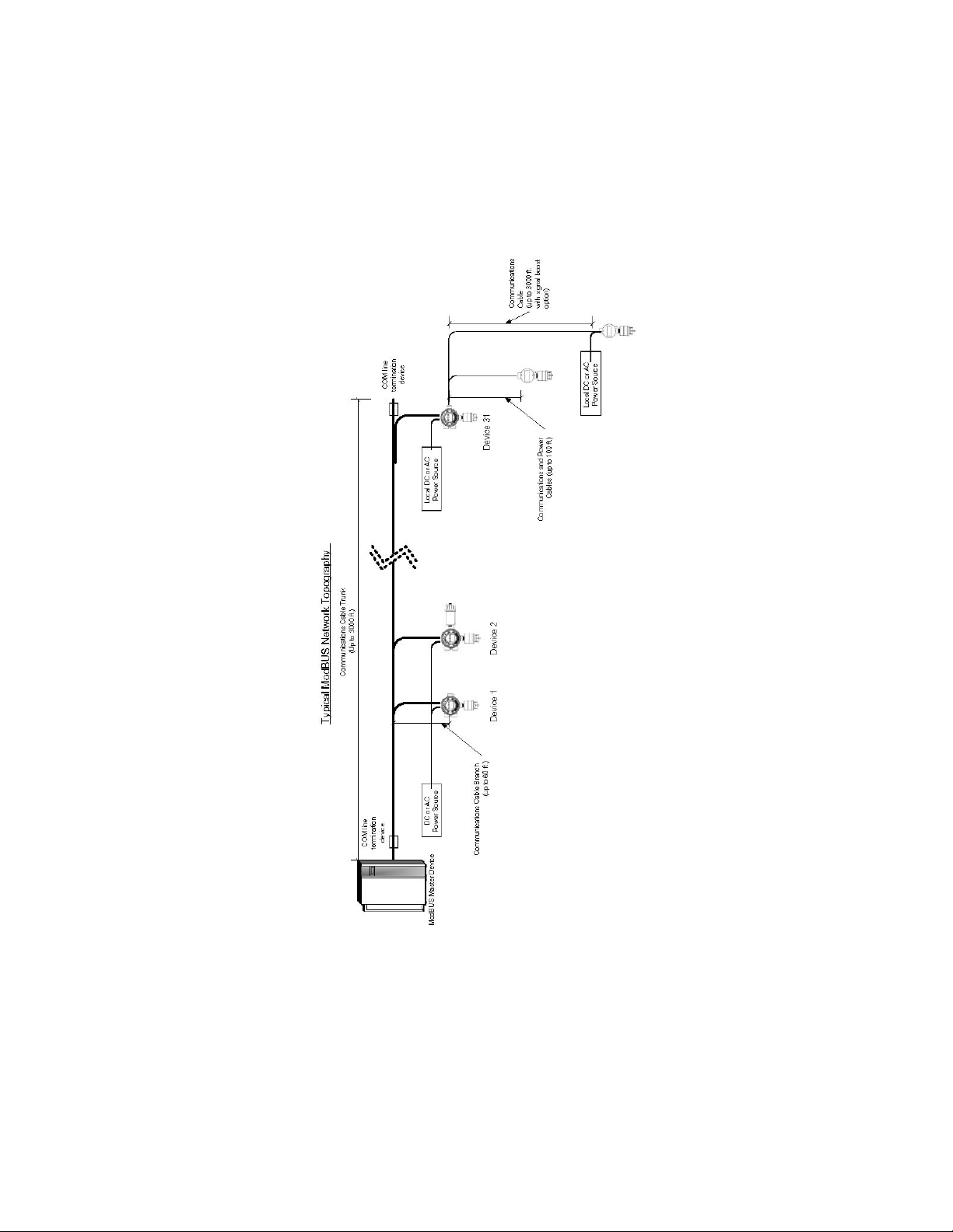
Figure 1-1. Typical ModBUS Network Topography
1-3
Page 7

Table 1-1. Maximum Power Cable Length
CONFIGURATION MAXIMUM POWER CABLE LENGTH (IN FEET)
(WITH NOMINAL 24-VDC TRANSMITTER SUPPLY)
CATALYTIC XIR E-CHEM 16 AWG CABLE 14 AWG 12 AWG
[4.2 OHM [2.6 OHM [1.8 OHM
PER 1K FT.] PER 1K FT.] PER 1K FT.]
NO RELAY NO RELAY NO RELAY
RELAYS- OPTION- RELAYS OPTION RELAYS OPTION
0 0 3 4500 3500 7500 5500 10,000 7,500
0 2 1 2000 1500 2750 2500 4,000 3,500
0 1 2 3000 2250 4500 3500 6,250 5,000
1 0 2 3500 2750 5500 4250 7,500 6,000
1 1 1 2000 1500 2750 2500 4,000 3,500
2 0 1 2500 1850 3500 3000 5,000 4,000
3 0 0 2000 1500 2750 2500 3,750 3,500
Daisy chaining power to multiple sensors is not recommended.
Table 1-2. Transmitter Power Consumption (7-30 VDC Supply)
CONFIGURATION MAX. POWER MAX. POWER
CONSUMPTION CONSUMPTION
CATALYTIC XIR* E-CHEM* WITH RELAYS CLOSED WITH RELAYS OPEN
0 0 3 2.5 W 1.5W
0 2 1 9.5 W 8.5W
0 1 2 7.0 W 6.0 W
1 0 2 6.0 W 5.0 W
1 1 1 6.5 W 5.5 W
2 0 1 8.0 W 7.0 W
3 0 0 10.0 W 9.0 W
*Combinations shown represent maximum loads that may be powered from one
transmitter without remote power.
NOTE: Only use single catalytic or XIR sensor configuration with 7 W power supply.
If at least one sensor is remote with signal boost or has remote power, any combination is available.
Recommended power supply selection is for operation not to exceed 65% of capacity.
See Installation Outline Drawings for details.
Table 1-3.
Remote Sensor Power Consumption (AC or DC Operation)
SENSOR TYPE MAXIMUM POWER CONSUMPTION
Catalytic* 4.5 W
XIR* 5.0 W
E-Chem 1.5 W
*The input for the 240 VAC Remote XIR and XE Sensors shall be additionally limited to
3.5 A.
1-4
Page 8
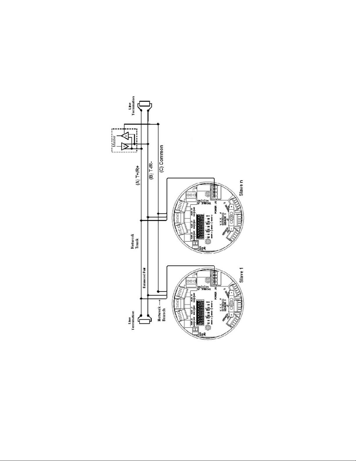
Figure 1-2. Typical Communications Wiring Scheme
1-5
Page 9
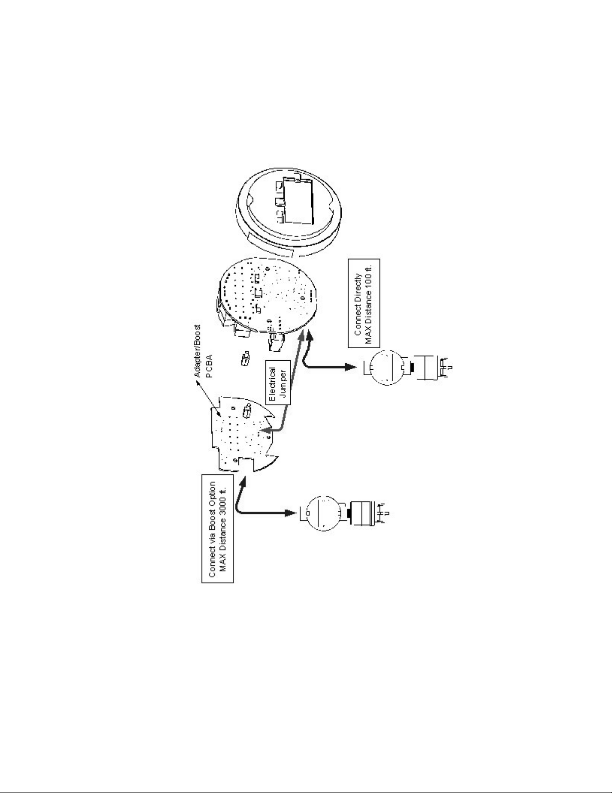
Figure 1-3. Signal-Boost Sensor Diagram
1-6
Page 10

Section 2,
Typical Communication Cable Wiring
for Signal Boost (FIGURE 2-1)
Operation
Display:
• Displays sensor type and gas level for each sensors
• Cycles through the sensors
• Sensor number graphic identifies sensor number
(see FIGURE 2-2)
• Latches on an Alarm or Fault condition and requires user
acknowledgment prior to resuming cycling
• If multiple conditions exist, reveals the subsequent alarm/fault
condition when one condition is acknowledged
• Resumes cycling through display screens when all conditions are
acknowledged.
• Alarm and fault conditions are indicated by alarm and the
corresponding number of the alarm level(s) that are activated
Relays:
• Gas processing and alarm activation continues even when a
display is locked on a screen
• Are common to all sensors by default
• Can be assigned specifically to a sensor by enabling only one level
of alarm for each sensor
• This may be accomplished through an Ultima X Controller
(see Section 2, "Calibration") consistent with the existing
Ultima X procedures or through a ModBUS controller
• Form C contacts, 5 A resistive, 30 VDC, 250 VAC
• May be configured as
• Normally energized/de-energized
• Increasing/decreasing level alarm
• Latching/non-latching
2-1
Page 11

Figure 2-1. Typical Communication Cable Wiring for Signal
Boost Option
SIG + SIG + SIG +SIG - SIG - SIG -
COMMON COMMON COMMON
Ultima X3 Transmitter
Sensor 1
Sensor 1 Sensor 2Sensor 3
SIG +
SIG -
COMMON
L1
L2
GND
DC +
DC -
SIG +
SIG -
COMMON
DC +
DC -
SIG +
SIG -
COMMON
Sensor 2
Sensor 3
Local AC power
with AC power option
Local DC power
with DC power option
Local DC
power with
DC power
option
2-2
Page 12

Figure 2-2. Sensor Display Screens
2-3
Page 13

Sensor:
• Automatically recognized when connected to a transmitter
• When removed, causes a "Sensor Missing" fault; this can be
corrected by:
• Reconnecting a sensor to that position or
• Manually taking the sensor 'off-line' via:
• Ultima X Controller, by sending a sensor disable command
• ModBUS command write to a control register.
• A missing sensor or unused sensor position returns a gas value of
-99.9 in response to a ModBUS request for gas level value starting
at address base +207.
Alarm Status Screen
(FIGURE 2-3)
In the North American version of the Ultima X with X3 Technology, a
screen will appear when a combustible sensor crosses 50%, 60% or
90% of the full-scale range.
• This screen:
• will override all sensor data or fault screens and will clear when
all sensors are below 50% of scale.
• can be acknowledged by the operator; the:
• instrument will go back to normal display operation until the
sensor or any other sensor crosses 50%, 60% or 90% of
scale
• normal operation status screen will display again.
• can be acknowledged through the:
• Ultima X Controller
• Pushbutton or
• MODBUS interface.
NOTE: All IR inputs will be functional and appropriate display
screens will display for the received IR message.
2-4
Page 14

Table 2-1. Status Indication Codes
CODE INDICATION
“d” Sensor position disabled
“F” Sensor position in a fault state
“N” Sensor position in normal operation, below 50% of range, and not in alarm
“A” Sensor position in alarm
“L” Sensor position at or above 50% of range
“M” Sensor position at or above 60% of range
“H” Sensor position at or above 90% of range
• The SENSOR, ALARM #1, #2, #3 indicators will still function as
normal cycling though each sensor position. This allows the:
• use of the IR signal to be received for each sensor position
• user to see what alarms are active for each sensor when the
status screen is displayed.
NOTE: In the CSA mode, the display (alarm/fault) locking feature will
be removed. This will allow the display to continuously cycle
through the three sensors. In doing so, the alarm flags will be
displayed as the instrument cycles, preventing the need to display the status screen upon alarm.
A. Indicates the status of Sensor #1.
B. Indicates the status of Sensor #2.
C. Indicates the status of Sensor #3.
Figure 2-3. Alarm Status Screen
2-5
Page 15

Ultima X Controller or Ultima X Calibrator:
• May be used to send commands to display data or set
configurations consistent with existing Ultima X procedures
• May be sent at any time for transmitter-specific commands, such
as address, baud rate, etc.
• Sensor-specific commands
(such as calibration initiation or span value) must be sent while the
sensor data (sensor type or gas levels) is displayed
Calibration
Calibration is performed via the:
• Ultima X Controller
• Sends a zero or span command
• Sensor calibration depends on the sensor number showing on
the display when the command is received.
• Push-button
• Depends on the sensor number showing on the display when
the command is received.
• Press and release push-button to acknowledge any conditions
• With the desired sensor data (sensor or gas level) on the
display, press the push-button to activate a calibration
• Calibration function depends on length of time that the pushbutton is pressed
• 5 seconds: zero calibration
• 10 seconds: span calibration
• 20 seconds: factory initial calibration
• Push-button may be factory/user-installed (FIGURE 2-4).
• See Installation Outline Drawings for details.
2-6
Page 16

• ModBUS Port
• See ModBUS data table definition in this addendum.
During the calibration process, the transmitter is in
Maintenance mode, all alarming is inhibited for all sensors,
and transmitter will not alert user to potential hazardous situations.
• During the calibration of a sensor, a ModBUS request for the gas
level returns the actual value. The other sensors on that specific
transmitter are not active. A gas level of -99.9 will be returned to
indicate that.
ModBUS Communications
Baud rate and data format defaults per data table specification are
adjustable by using a:
• Hand-held Controller or
• ModBUS command.
Each transmitter:
• Is a slave on the communications network
• Must have a unique address and serial format compatible with
transmitter configuration.
""
WARNING
Figure 2-4. Push-button Wiring
2-7
Page 17

Section 3,
ModBUS
ModBUS Addressing
The ModBUS slave address has a valid range of 1-247.
• 247 is the default value.
This address may be set by:
• The Ultima X Controller:
• Send an address command with the desired value.
• The Ultima X Calibrator:
• Press the ADDRESS button once to display the current setting.
• The ZERO button increments the address number
• The SPAN button decrements the address number
• Range for Calibrator is 1 - 32; use Controller for other
addresses
• Press the ADDRESS button again to save the new address.
• A ModBUS controller by writing to the corresponding register in the
data table.
ModBUS Communications
• The communications protocol is ModBUS RTU over an RS-485
hardware network.
• The default settings for communications parameters are 19200
baud and even parity.
• The stop bits are fixed at 1 stop bit.
• For data types that are larger than one word, the most significant
word is located in the first register (big-endian).
Table 3-1. Supported ModBUS Function Codes
FUNCTION
NUMBER DESCRIPTION
3 Read Holding Registers
5 Write Single Coil
6 Write Single Register
16 Write Multiple Registers
3-1
Page 18

Table 3-2. ModBUS Memory Map Overview
The Modbus port allows for access to a significant amount of information which may be
necessary for your system integration requirements. As a minimum, the gas readings and
fault status registers should be polled.
DESCRIPTION START END SIZE IN ACCESS
ADDRESS ADDRESS WORDS
ModBUS Data Table
Start Base Address 1000 1000 1 Read/Write
Factory Configuration
Data Base+1 Base+18 18 Read Only
User Configuration
Data Base+101 Base+148 48 Read/Write
Status Information Base+201 Base+253 53 Read Only
Control Words
Base+301 Base+302 2 Read/Write
ModBUS Base Address (Read/Write)
The ModBUS base address register is located at address 1000 and has
a default value of 40,000.
• This may be changed by writing a new value within the permissible
range to that address.
• Subsequent addresses must take this new base address into
consideration.
• The base address may be changed by writing to address 1000,
regardless of its contents.
Table 3-3. ModBUS Bas Address (Read/Write)
DESCRIPTION ADDRESS POSSIBLE VALUES
ModBUS Data
Table Base Address 1000 1000 - 60,000
(default 40,000)
• For systems that use five-digit addressing, 4XXXX:
• If the first digit is an internal system requirement and does not
appear in the communications packet, write the value 1000 to
address 41000. The base address is now 41000 and the first
valid address is 41001.
• If all five digits appear in the communications packet, the
default base address is 40000 and the first valid address is
40001.
3-2
Page 19

• For systems that use six-digit addressing, 4XXXXX:
• The first digit is an internal system requirement and does not
appear in the communications packet. The base address is
440000, and the first valid address is 440001.
Table 3-4. ModBUS Factory Configuration Data (Read Only)
DESCRIPTION ADDRESS POSSIBLE VALUES
Device Type Base+1 3(Ultima X3 US)
4(Ultima X3 Europe)
Firmware Version Base+2 0..32767 Integer,
divide by 100 for range
00.00 to 99.99
Relays Option Installed Base+3 0-Relays not installed,
1-Relays installed
Reserved for future use Base+4
Date of Mfg Year, Sensor 1 Base+5 20XX
Date of Mfg Month, Sensor 1 Base+6 1..12
Date of Mfg Day, Sensor 1 Base+7 1..31
Date of Mfg Year, Sensor 2 Base+8 20XX
Date of Mfg Month, Sensor 2 Base+9 1..12
Date of Mfg Day, Sensor 2 Base+10 1..31
Date of Mfg Year, Sensor 3 Base+11 20XX
Date of Mfg Month, Sensor 3 Base+12 1..12
Date of Mfg Day, Sensor 3 Base+13 1..31
Full Scale RangeDefault Sensor 1 Base+14 Single Precision Float
Full Scale RangeDefault Sensor 2 Base+16 Single Precision Float
Full Scale RangeDefault Sensor 3 Base+18 Single Precision Float
3-3
Page 20

Table 3-5. ModBUS User Configuration Data (Read/Write)
DESCRIPTION
ADDRESS POSSIBLE VALUES
ModBUS Slave Address Base+101 1..247
Baud Rate Code Base+102 0 - 1200, 1 - 2400
2 - 4800, 3 - 9600
4 - 19200 (default)
Parity Code Base+103 0 - Even (default)
1 - Odd
2 - None
For future use Base+104
For future use Base+105
For future use Base+106
Full Scale Range, Sensor 1 Base+107 Single Precision Float
Full Scale Range, Sensor 2 Base+109 Single Precision Float
Full Scale Range, Sensor 3 Base+111 Single Precision Float
Span Gas Value, Sensor 1 Base+113 Single Precision Float
Span Gas Value, Sensor 2 Base+115 Single Precision Float
Span Gas Value, Sensor 3 Base+117 Single Precision Float
Alarm 1 Setpoint, Sensor 1 Base+119 Single Precision Float
Alarm 1 Setpoint, Sensor 2 Base+121 Single Precision Float
Alarm 1 Setpoint, Sensor 3 Base+123 Single Precision Float
Alarm 2 Setpoint, Sensor 1 Base+125 Single Precision Float
Alarm 2 Setpoint, Sensor 2 Base+127 Single Precision Float
Alarm 2 Setpoint, Sensor 3 Base+129 Single Precision Float
Alarm 3 Setpoint, Sensor 1 Base+131 Single Precision Float
Alarm 3 Setpoint, Sensor 2 Base+133 Single Precision Float
Alarm 3 Setpoint, Sensor 3 Base+135 Single Precision Float
Alarm Function Word 1 Base+137 0..32767, See detail below
Alarm Function Word 2 Base+138 0..32767, See detail below
Average Time Interval Base+139 1,8 or 24
Current Date - Year Base+140 20XX
Current Date - Month Base+141 1..12
Current Date - Day Base+142 1..31
Current Time -Hour Base+143 1..24
Current Time - Minute Base+144 0..59
Current Time - Second Base+145 Read Only
Gas Table Number
Sensor 1 (XIR) Base+146 1 Methane, 2 Propane
3 Ethane, 4 Butane
5 Pentane, 6 Hexane
7 Cyclopentane, 8 Ethylene
Gas Table Number
Sensor 2 (XIR) Base+147 Same as above
Gas Table Number
Sensor 3 (XIR) Base+148 Same as above
3-4
Page 21

Table 3-6. Alarm Function Codes - Word 1
(Read/Write at Address Base+137)
NAME BITS FUNCTION DESCRIPTION
Alarm 1 Enable, Sensor 1 0 1-Enable, 0-Disable
Alarm 1 Enable, Sensor 2 1 1-Enable, 0-Disable
Alarm 1 Enable, Sensor 3 2 1-Enable, 0-Disable
Alarm 2 Enable, Sensor 1 3 1-Enable, 0-Disable
Alarm 2 Enable, Sensor 2 4 1-Enable, 0-Disable
Alarm 2 Enable, Sensor 3 5 1-Enable, 0-Disable
Alarm 3 Enable, Sensor 1 6 1-Enable, 0-Disable
Alarm 3 Enable, Sensor 2 7 1-Enable, 0-Disable
Alarm 3 Enable, Sensor 3 8 1-Enable, 0-Disable
Alarm 1 Direction, Sensor 1 9 1-Increasing, 0-Decreasing
Alarm 1 Direction, Sensor 2 10 1-Increasing, 0-Decreasing
Alarm 1 Direction, Sensor 3 11 1-Increasing, 0-Decreasing
Alarm 2 Direction, Sensor 1 12 1-Increasing, 0-Decreasing
Alarm 2 Direction, Sensor 2 13 1-Increasing, 0-Decreasing
Alarm 2 Direction, Sensor 3 14 1-Increasing, 0-Decreasing
Not used 15
Table 3-7. Alarm Function Codes - Word 2
(Read/Write at Address Base+138)
NAME BITS FUNCTION DESCRIPTION
Alarm 3 Direction, Sensor 1 0 1-Increasing, 0-Decreasing
Alarm 3 Direction, Sensor 2 1 1-Increasing, 0-Decreasing
Alarm 3 Direction, Sensor 3 2 1-Increasing, 0-Decreasing
Alarm 1 Latch Status, Sensor 1 3 0 - Non-Latching, 1 - Latching
Alarm 1 Latch Status, Sensor 2 4 0 - Non-Latching, 1 - Latching
Alarm 1 Latch Status, Sensor 3 5 0 - Non-Latching, 1 - Latching
Alarm 2 Latch Status, Sensor 1 6 0 - Non-Latching, 1 - Latching
Alarm 2 Latch Status, Sensor 2 7 0 - Non-Latching, 1 - Latching
Alarm 2 Latch Status, Sensor 3 8 0 - Non-Latching, 1 - Latching
Alarm 3 Latch Status, Sensor 1 9 0 - Non-Latching, 1 - Latching
Alarm 3 Latch Status, Sensor 2 10 0 - Non-Latching, 1 - Latching
Alarm 3 Latch Status, Sensor 3 11 0 - Non-Latching, 1 - Latching
Relay Statewithout alarm condition 12 1 - Normally Energized,
0 - Normally De-Energized
Relay Statewithout alarm condition 13 1 - Normally Energized,
0 - Normally De-Energized
Relay Statewithout alarm condition 14 1 - Normally Energized,
0 - Normally De-Energized
Not used 15
3-5
Page 22

Table 3-8. ModBUS Device Status (Read only)
DESCRIPTION ADDRESS POSSIBLE VALUES
General Status Bits Base+201 0..32767, See details below
Fault Status Bits Base+202 0..32767, See details below
Reserve Base+203
Gas Type - Sensor 1 Base+204 See TABLE 3-14 for details
Gas Type - Sensor 2 Base+205 See TABLE 3-14 for details
Gas Type - Sensor 3 Base+206 See TABLE 3-14 for details
Gas Level - Sensor 1 Base+207 Single Precision Float
Gas Level - Sensor 2 Base+209 Single Precision Float
Gas Level - Sensor 3 Base+211 Single Precision Float
Engineering Units - Sensor 1 Base+213 See TABLE 3-15 for details
Engineering Units - Sensor 2 Base+214 See TABLE 3-15 for details
Engineering Units - Sensor 3 Base+215 See TABLE 3-15 for details
Calibration Step Base+216 0. 30 Sec Countdown
to Start Zero
1. Waiting for Zero
2. 30 Sec Countdown
to Start SPAN
3. Waiting for SPAN
4. Calibration Aborted
5. Zero Cal Fault
6. Span Cal Fault
7. Calibration Completed Successfully
Temperature - Sensor 1 Base+217 Signed Integer
Temperature - Sensor 2 Base+218 Signed Integer
Temperature - Sensor 3 Base+219 Signed Integer
Min Gas Reading over
average Interval - Sensor 1 Base+220 Single Precision Float
Min Gas Reading over
average Interval - Sensor 2 Base+222 Single Precision Float
Min Gas Reading over
average Interval - Sensor 3 Base+224 Single Precision Float
Max Gas Reading over
average Interval - Sensor 1 Base+226 Single Precision Float
Max Gas Reading over
average Interval - Sensor 2 Base+228 Single Precision Float
Max Gas Reading over
average Interval - Sensor 3 Base+230 Single Precision Float
Avg Gas Reading over
average Interval - Sensor 1 Base+232 Single Precision Float
Avg Gas Reading over
average Interval - Sensor 2 Base+234 Single Precision Float
Avg Gas Reading over
average Interval - Sensor 3 Base+236 Single Precision Float
Date of Last Cal Year,
Sensor 1 Base+238 20XX
3-6
Page 23

Date of Last Cal Month,
Sensor 1 Base+239 1..12
Date of Last Cal Day
Sensor 1 Base+240 1..31
Date of Last Cal Year,
Sensor 2 Base+241 20XX
Date of Last Cal Month,
Sensor 2 Base+242 1..12
Date of Last Cal Day,
Sensor 2 Base+243 1..31
Date of Last Cal Year,
Sensor 3 Base+244 20XX
Date of Last Cal Month,
Sensor 3 Base+245 1..12
Date of Last Cal Day,
Sensor 3 Base+246 1..31
Drift counter- Sensor 1 Base+247 0..20
Drift counter- Sensor 2 Base+248 0..20
Drift counter- Sensor 3 Base+249 0..20
Internal Error Code Ultima X Base+250 For future implementation
Internal Error Code Sensor 1 Base+251 For future implementation
Internal Error Code - Sensor 2 Base+252 For future implementation
Internal Error Code - Sensor 3 Base+253 For future implementation
Information Flags 1 Base+254 See TABLE 3-16
Information Flags 2 Base+255 See TABLE 3-17
Information Flags 3 Base+256 See TABLE 3-18
Information Flags 4 Base+257 See TABLE 3-19
Alternate Gas Reading Sensor 1 Base+258 See TABLE 3-20
Alternate Gas Reading Sensor 2 Base+259 See TABLE 3-20
Alternate Gas Reading Sensor 3 Base+260 See TABLE 3-20
3-7
Page 24

Table 3-9. ModBUS General Status Bits
(Read Only at address Base+201)
NAME BIT FUNCTION DESCRIPTION
Device Fault (any fault) 0 Set for all fault conditions
Calibration Active - Sensor 1 1 Set during calibration
Calibration Active - Sensor 2 2 Set during calibration
Calibration Active - Sensor 3 3 Set during calibration
Warm up Mode 4 Set during startup
Low Alarm Active 5 Set while alarm relay is active
N/A Horn Relay Software
Mid Alarm Active 6 Set while alarm relay is active
High Alarm Active 7 Set while alarm relay is active
For future use 8
For future use 9
For future use 10
For future use 11
For future use 12
For future use 13
For future use 14
Not used 15
Table 3-10. ModBUS Fault Status Bits
(Read Only at address Base+202)
NAME BIT FUNCTION DESCRIPTION
Fault Relay Active 0 Set when any fault is detected
Sensor Missing - Sensor 1 1 Set when this fault is detected
Sensor Missing - Sensor 2 2 Set when this fault is detected
Sensor Missing - Sensor 3 3 Set when this fault is detected
Calibration Fault - Sensor 1 4 Set when this fault is detected
Calibration Fault - Sensor 2 5 Set when this fault is detected
Calibration Fault - Sensor 3 6 Set when this fault is detected
Power Fail Fault - Sensor 1 7 Set when this fault is detected
Power Fail Fault - Sensor 2 8 Set when this fault is detected
Power Fail Fault - Sensor 3 9 Set when this fault is detected
Power Fail Fault Main Unit +5VDC 10 Set when this fault is detected
Sensor End of life - Sensor 1 11 Set when this fault is detected
Sensor End of life - Sensor 2 12 Set when this fault is detected
Sensor End of life - Sensor 3 13 Set when this fault is detected
Ultima X Configuration Reset 14 Set when a datasheet reset occurs
Not used 15
3-8
Page 25

Table 3-11. Control Words (Read/Write)
DESCRIPTION ADDRESS POSSIBLE VALUES
Command Word 1 Base+301 0 to 32767, See TABLE 3-12
Command Word 2 Base+302 0 to 32767, See TABLE 3-13
Table 3-12. ModBUS Command Word 1
(Read at address Base+301/Write Coils 1 through 16)
NAME BITS COIL FUNCTION DESCRIPTION
Start Full ICAL Calibration Sensor 1 0 1 Rtn's fault if any
Calibration in progress
Start Full ICAL Calibration Sensor 2 1 2 Rtn's fault if any
Calibration in progress
Start Full ICAL Calibration Sensor 3 2 3 Rtn's fault if any
Calibration in progress
Start Standard Full Calibration Sensor 1 3 4 Rtn's fault if any Calibration in progress
Start Standard Full Calibration Sensor 2 4 5 Rtn's fault if any Calibration in progress
Start Standard Full Calibration Sensor 3 5 6 Rtn's fault if any Calibration in progress
Start Standard Zero Calibration
Sensor 1 6 7 Rtn's fault if any Calibration in progress
Start Standard Zero Calibration
Sensor 2 7 8 Rtn's fault if any Calibration in progress
Start Standard Zero Calibration
Sensor 3 8 9 Rtn's fault if any Calibration in progress
Start UCAL Calibration Sensor 1 9 10 Rtn's fault if any Calibration in progress
Start UCAL Calibration Sensor 2 10 11 Rtn's fault if any Calibration in progress
Start UCAL Calibration Sensor 3 11 12 Rtn's fault if any Calibration in progress
Step UCAL 12 13 1 to step
Abort Calibration (any) 13 14 1 to abort
Reserved for future use 14 15
Not used 15 16
3-9
Page 26

Table 13-13 ModBUS Command Word 2
(Read at address Base+302/Write Coils 17 through 32)
NAME BIT COIL FUNCTION DESCRIPTION
Sensor Swap Delay 0 17 1-Enable, 0-Disable
Alert Option Enable 1 18 1-Enable, 0-Disable
Acknowledge or
Reset Latched Alarms(ACK) 2 19 1 to initiate (same functionality as Push-
button or IR command)
Reset Main Board and sensors 3 20 1 to initiate
For future use 4 21
For future use 5 22
Reset Data Sheet - Sensor 1 6 23 1 to initiate
Reset Data Sheet - Sensor 2 7 24 1 to initiate
Reset Data Sheet - Sensor 3 8 25 1 to initiate
Disable Sensor 1 9 26 1 to Disable
Disable Sensor 2 10 27 1 to Disable
Disable Sensor 3 11 28 1 to Disable
Reserved for future use 12 29
Reserved for future use 13 30
Reserved for future use 14 31
Not used 15 32
Table 3-14. Sensor Type
SENSOR TYPE
VALUE SENSOR TYPE
13 COMB-1S 100% LEL, 1% LEL, 25% LEL (0.6% Propane)
257 CO 100 PPM, 1 PPM, MSA 25E/F, 60 PPM
258 CO 500 PPM, 1 PPM, MSA 25E/F, 300 PPM
259 SO225 PPM, 1 PPM, CTL 7ST/F, 10 PPM
260 H2S 10.0 PPM, 0.1 PPM, MSA HS25B, 5.0 PPM
261 H2S 50.0 PPM, 0.1 PPM, MSA HS25B, 40 PPM
262 H2S 100 PPM, 1 PPM, MSA HS25D, 40 PPM
263 NO 100 PPM, 1 PPM, CTL 7NT, 50 PPM
264 NO210.0 PPM, 0.1 PPM, MSA ND25C, 5.0 PPM
265 CL25.0 PPM, 0.1 PPM, MSA CL25B, 2.0 PPM
266 HCN 50 PPM, 1 PPM, MSA HN25C, 10 PPM
267 HCL 50 PPM, 1 PPM, MSA HL25C, 40 PPM
12 O225.0%, 0.1%, MSA 10019727, 20.8%
14 COMB-1S 100%LEL, 1% LEL, 40% LEL
3-10
Page 27

15 COMB-1S 100%LEL, 1% LEL, 55% LEL
16 COMB-1S-NL 100%LEL, 1% LEL, 25% LEL
17 COMB-1S-NL 100%LEL, 1% LEL, 40% LEL
18 COMB-1S-NL 100%LEL, 1% LEL, 55% LEL
275 CLO23.0 PPM, 0.1 PPM, MSA 7CLH, 1.0 PPM
276 NH3100 PPM, 1 PPM, SENSORIC, 25 PPM
277 H2, 1000 PPM, 10 PPM, CTL 7HYT, 300 PPM
279 PHOSPHINE, 2.0 PPM, 0.1 PPM CTL 7SH, 0.5 PPM
280 ARSINE, 2.0 PPM, 0.1 PPM, CTL 7SH, 1.0 PPM
281 SILANE, 25 PPM, 1 PPM, CTL 7SH, 5 PPM
282 GERMANE, 3.0 PPM, 0.1 PPM, CTL 7SH, 2.5 PPM
283 DIBORANE, 50 PPM, 1 PPM, CTL 7SH, 15 PPM
284 FLUORINE, 5.0 PPM, 0.1 PPM, MSA 7CLH, 4.0 PPM
285 HF
286 BROMINE, 5.0 PPM, 0.1 PPM, MSA 7CLH, 2.5 PPM
287 ETO, 10.0 PPM, 0.1 PPM, 5 PPM
288 O210.0%, 0.1% MSA 10019727, 5.0%
2 IRIS
19 COMB-1S-100% LEL, 10% LEL, 31% LEL
20 COMB-1S-100% LEL, 1% LEL, 49% LEL
21 COMB-1S-100% LEL, 1% LEL, 68% LEL
22 Tankerguard
290 CLO20.02 resolution
289 NH41000
291 H2S 500
3 Custom IRIS 0-10000 PPM
101 IRIS - start
to IRIS - cont.
150 IRIS - finish
Table 3-15. Sensor Engineering Units
UNIT LABEL VALUE UNIT LABEL
0 None
1 % LEL
2%
3 PPM
4 Future Expansion
3-11
Page 28

Table 3-16. Information Flags Word #1 –
(Read at address Base+254)
NAME BITS FUNCTION DESCRIPTION
Sen
sor # 1 Disabled 0 0 = enabled, 1 = disabled
Sensor # 2 Disabled 1 0 = enabled, 1 = disabled
Sensor # 3 Disabled 2 0 = enabled, 1 = disabled
Alarm # 1 Sensor # 1 3 0 = clear, 1 = set
Alarm # 2 Sensor # 1 4 0 = clear, 1 = set
Alarm # 3 Sensor # 1 5 0 = clear, 1 = set
Alarm # 1 Sensor # 2 6 0 = clear, 1 = set
Alarm # 2 Sensor # 2 7 0 = clear, 1 = set
Alarm # 3 Sensor # 2 8 0 = clear, 1 = set
Alarm # 1 Sensor # 3 9 0 = clear, 1 = set
Alarm # 2 Sensor # 3 10 0 = clear, 1 = set
Alarm # 3 Sensor # 3 11 0 = clear, 1 = set
Cal Fault Condition Sensor #1 12 0 = Zero, 1 = Span
Cal Fault Condition Sensor #2 13 0 = Zero, 1 = Span
Cal Fault Condition Sensor #3 14 0 = Zero, 1 = Span
Not Used 15
Table 3-17. Information Flags Word #2
(Read at address Base+255)
NAME BITS FUNCTION DESCRIPTION
Configuration Reset 0 Set if TRUE
Fault RAM Main 1 Set if TRUE
FAULT FLASH MAIN 2 Set if TRUE
EEPROM WRITE ERROR 3 Set if TRUE
MUX FAULT 4 Set if TRUE
FAULT INCOMPATIBLE
SENSOR #1 5 Set if TRUE
FAULT INCOMPATIBLE
SENSOR #2 6 Set if TRUE
FAULT INCOMPATIBLE
SENSOR #3 7 Set if TRUE
Quick under range sensor #1 8 Set if TRUE
Quick under range sensor #2 9 Set if TRUE
Quick under range sensor #3 10 Set if TRUE
Under range Sensor #1 11 Set if TRUE
Under range sensor #2 12 Set if TRUE
Under range sensor #3 13 Set if TRUE
Atex Enabled 14 0 = Disabled, 1 = Enabled
Swap Delay 15 0 = Disabled, 1 = Enabled
3-12
Page 29

Table 3-18. Information Flags Word #3
(Read at address Base+26)
NAME BITS FUNCTION DESCRIPTION
Overrange Flag sensor #1 0 Set if TRUE
Overrange Flag sensor #21 1 Set if TRUE
Overrange Flag sensor #31 2 Set if TRUE
LOC Flag sensor #1 1 3 Set if TRUE
LOC Flag sensor #2 1 4 Set if TRUE
LOC Flag sensor #3 1 5 Set if TRUE
Parameter Fault Sensor #1 6 Set if TRUE
Parameter Fault Sensor #2 7 Set if TRUE
Parameter Fault Sensor #3 8 Set if TRUE
Warm up Sensor #1 1 9 Set if TRUE
Warm up Sensor #2 1 10 Set if TRUE
Warm up Sensor #3 1 11 Set if TRUE
Sensor Configuration Reset #1 12 Set if TRUE
Sensor Configuration Reset #2 13 Set if TRUE
Sensor Configuration Reset #3 14 Set if TRUE
Not Used 15
Table 3-19. Information Flags Word #4
(Read at address Base+257)
NAME BITS FUNCTION DESCRIPTION
Underrange Average Interval S1 0 Set if TRUE
Underrange Average Interval S2 1 Set if TRUE
Underrange Average Interval S3 2 Set if TRUE
Overrange Average Interval S1 3 Set if TRUE
Overrange Average Interval S2 4 Set if TRUE
Overrange Average Interval S3 5 Set if TRUE
Sensor Warning Sensor #1 6 Set if TRUE
Sensor Warning Sensor #2 7 Set if TRUE
Sensor Warning Sensor #3 8 Set if TRUE
Not Used 9
Not Used 10
Not Used 11
Not Used 12
Not Used 13
Not Used 14
Not Used 15
3-13
Page 30

Table 3-20. Alternate Gas Readings
(Read/Write at address Base+258 to Base+260)
DESCRIPTION VALUE
Normal Gas Detection 400-2000
Fault 230
Overrange 2110
Suppressed 305
Disabled 0
3-14
 Loading...