

Page 1

Hydrogen Sulfide Gas Detection
Ultima® MOS-5
Intelligent Sensor for
The information and technical data disclosed in
this document may be used and disseminated
only for the purposes and to the extent
specifically authorized in writing by MSA.
Instruction Manual 04-14
MSA reserves the right to change published
specifications and designs without prior notice.
Part No. MANMOS5
Revision 1
MANMOS5
Page 2

Ultima MOS-5 Detector
This page intentionally left blank
i
Page 3

Ultima MOS-5 Detector
Table of Contents
TABLE OF FIGURES .................................................................................................................. VI
TABLE OF TABLES ................................................................................................................... VII
QUICK START GUIDE ................................................................................................................. 1
Mounting and Wiring ............................................................................................................................... 1
Tools Required ……..…………………………………………………………………………………………...1
Terminal Connections ............................................................................................................................. 1
1.0 INTRODUCTION .................................................................................................................... 4
1.1 Protection for Life ....................................................................................................................... 4
1.2 Special Warnings ....................................................................................................................... 4
1.3 System Integrity Verification ...................................................................................................... 5
2.0 PRODUCT DESCRIPTION ..................................................................................................... 7
2.1 General Description ................................................................................................................... 7
3.0 INSTALLATION ...................................................................................................................... 8
3.1 Receipt of Equipment ................................................................................................................. 8
3.2 Tools Required ........................................................................................................................... 8
3.3 Choosing Product Locations ...................................................................................................... 8
3.3.1 Remote Mounting of the Sensor from the Electronics .................................................. 9
3.4 Mounting and Wiring ................................................................................................................ 10
3.5 Terminal Connections .............................................................................................................. 11
3.5.1 Terminal Block TB1 – Sensor Connections ................................................................ 11
3.5.2 Terminal Block TB2 – Power and Signal Connections ............................................... 12
3.5.3 DC Power and Ground Connections ........................................................................... 13
3.5.4 Analog Signal Connections ......................................................................................... 13
3.5.5 Terminal Block TB3 – Relay Connections .................................................................. 14
3.5.6 European Union (EU) Approved Applications ............................................................. 15
3.5.7 Cable Termination in the Non-hazardous Area .......................................................... 15
3.6 Maintaining the X/P Integrity .................................................................................................... 15
4.0 OPERATION ......................................................................................................................... 17
4.1 Start-Up Checklist .................................................................................................................... 17
4.2 Start-Up .................................................................................................................................... 17
4.3 Relay Reset .............................................................................................................................. 17
4.4 User Selectable Options .......................................................................................................... 18
4.4.1 Ultima MOS-5 Intelligent Sensor User Menu Structure .............................................. 19
4.4.2 Sensor Range ............................................................................................................. 19
4.4.3 Calibration Output ....................................................................................................... 20
4.4.4 Warning Relay Settings .............................................................................................. 20
4.4.5 Alarm Relay Settings................................................................................................... 21
4.4.6 Modbus Channel 1 Settings ........................................................................................ 21
4.4.7 Modbus Channel 2 Settings ........................................................................................ 22
ii
Page 4

Ultima MOS-5 Detector
4.5
HART........................................................................................................................................ 22
4.6 Gas Check Mode ..................................................................................................................... 23
4.6.1 Procedure for Checking the Calibration ...................................................................... 23
4.7 Calibration ................................................................................................................................ 24
4.7.1 Calibration Procedure ................................................................................................. 24
4.7.2 Aborting Calibration..................................................................................................... 25
4.7.3 Remaining Sensor Life ................................................................................................ 25
4.7.4 Initializing the Remaining Sensor Life ......................................................................... 26
4.8 Calibration Equipment .............................................................................................................. 26
4.8.1 Calibrating with a Breaker Bottle and Ampoules ........................................................ 26
4.8.2 Calibrating with an H2S Portable Purge Calibrator ..................................................... 26
5.0 MAINTENANCE ................................................................................................................... 28
5.1 General Maintenance ............................................................................................................... 28
5.2 Storage ..................................................................................................................................... 28
6.0 TROUBLESHOOTING ......................................................................................................... 29
6.1 Fault Codes and Their Remedies ............................................................................................ 29
6.1.1 F2 - Failed to Complete the Calibration ...................................................................... 29
6.1.2 F3 Flash Checksum Error ........................................................................................... 29
6.1.3 F4 - Sensor Heater Open Error or Sensor Amplifier Error .......................................... 29
6.1.4 F5 - Sensor Heater Shorted Error ............................................................................... 30
6.1.5 F6 - Low Supply Voltage ............................................................................................. 30
6.1.6 F7 - EEPROM Verification Failure .............................................................................. 30
6.1.7 F8 - Failure to Complete Setup ................................................................................... 30
6.1.8 F9 - Gas Check Period Exceeded .............................................................................. 31
6.1.9 F10 – Switch Error ...................................................................................................... 31
6.1.10 F11 Internal Error ........................................................................................................ 31
7.0 CUSTOMER SUPPORT ....................................................................................................... 32
7.1 MSA Office ............................................................................................................................... 32
8.0 MODBUS INTERFACE ........................................................................................................ 33
8.1 Baud Rate ................................................................................................................................ 33
8.2 Data Format ............................................................................................................................. 33
8.3 Modbus Read Status Protocol (Query/Response) ................................................................... 33
8.3.1 Modbus Read Query Message ................................................................................... 33
8.3.2 Modbus Read Response Message ................................................................................. 35
8.4 Modbus Write Command Protocol (Query/Response) ............................................................ 35
8.4.1 Modbus Write Query Message ................................................................................... 35
8.4.2 Modbus Write Response Message ............................................................................. 35
8.5 Function Codes Supported ...................................................................................................... 36
8.6 Exception Responses and Exception Codes ........................................................................... 36
8.6.1 Exception Response ................................................................................................... 36
8.6.2 Exception Code ........................................................................................................... 37
8.7 Ultima MOS-5 Intelligent Sensor Command Register Locations ............................................. 38
8.8 Ultima MOS-5 Intelligent Sensor Command Register Details ................................................. 41
8.8.1 Analog (00H) ............................................................................................................... 41
8.8.2 Mode (01H) ................................................................................................................. 41
8.8.3 Status/Error (02H) ....................................................................................................... 41
iii
Page 5

Ultima MOS-5 Detector
8.8.4
Not Used (03H) ........................................................................................................... 42
8.8.5 Unit Type (04H) ........................................................................................................... 42
8.8.6 Software Revision (05H) ............................................................................................. 42
8.8.7 Status Block (06H) ...................................................................................................... 42
8.8.8 Analog Value (06H) ..................................................................................................... 42
8.8.9 Mode & Error (07H) ..................................................................................................... 42
8.8.10 Error Sensor & Sensor Life (08H) ............................................................................... 42
8.8.11 Display (0x09H & 0x0AH) ........................................................................................... 43
8.8.12 Serial Number (0BH/0CH) .......................................................................................... 43
8.8.13 Alarm Settings (0DH) .................................................................................................. 43
8.8.14 Warn Settings (0EH) ................................................................................................... 44
8.8.15 Com1 Address (0FH) .................................................................................................. 44
8.8.16 Com1 Baud Rate (10H) .............................................................................................. 44
8.8.17 Com1 Data Format (11H) ........................................................................................... 45
8.8.18 Com2 Address (12H) .................................................................................................. 45
8.8.19 Com2 Baud Rate (13H) .............................................................................................. 45
8.8.20 Com2 Data Format (14H) ........................................................................................... 45
8.8.21 Not Used (15H) ........................................................................................................... 46
8.8.22 Reset Alarms (16H) ..................................................................................................... 46
8.8.23 Sensor Life (17H) ........................................................................................................ 46
8.8.24 Sensor Scale (18H) ..................................................................................................... 46
8.8.25 MODEL 10K Controller (Co – Calibration Output) (19H) .......................................... 46
8.8.26 Not Used (1A, AB, 1C H) ............................................................................................ 46
8.9 HART Enable (1D H) ................................................................................................................ 46
8.9.1 HART Test (1Eh) ......................................................................................................... 46
8.9.2 Abort Calibration (1Fh) ................................................................................................ 47
8.9.3 Total Receive Errors (20H) ......................................................................................... 47
8.9.4 Bus Activity Rate % (21H) ........................................................................................... 47
8.9.5 Function Code Errors (22H) ........................................................................................ 47
8.9.6 Starting Address Errors (24H) ..................................................................................... 47
8.9.7 RXD CRC Errors Hi (25H) .......................................................................................... 47
8.9.8 RXD CRC Errors Lo (Same as Hi) (26H) .................................................................... 47
8.9.9 Parity Errors (27H) ...................................................................................................... 47
8.9.10 Overrun Errors (28H) .................................................................................................. 48
8.9.11 Framing Errors (29H) .................................................................................................. 48
8.9.12 Total Software CH1 Errors (2AH) ............................................................................... 48
8.9.13 Not Used (2BH) ........................................................................................................... 48
8.9.14 Clear Hardware Errors (2CH) ..................................................................................... 48
8.9.15 Clear Communication Errors (2DH) ............................................................................ 48
8.9.16 User Information (60H to 6FH) .................................................................................... 51
8.9.17 CH2 Total Receive Errors (70H) ................................................................................. 52
8.9.18 CH2 Bus Activity Rate % (71H) .................................................................................. 52
8.9.19 CH2 Function Code Errors (72H) ................................................................................ 52
8.9.20 CH2 Starting Address Errors (73H) ............................................................................ 52
8.9.21 CH2 Number of Register Errors (74H) ........................................................................ 52
8.9.22 CH2 RXD CRC Errors Hi (75H) .................................................................................. 52
8.9.23 CH2 RXD CRC Errors Lo (Same as Hi) (76H) ........................................................... 52
8.9.24 CH2 Parity Errors (77H) ............................................................................................. 52
8.9.25 CH2 Overrun Errors (78H) .......................................................................................... 52
8.9.26 CH2 Framing Errors (79H) .......................................................................................... 53
8.9.27 CH2 Total Software CH1 Errors (7AH) ....................................................................... 53
8.9.28 Not Used (7BH) ........................................................................................................... 53
iv
Page 6

Ultima MOS-5 Detector
8.9.29
CH2 Clear UART Errors (7CH) ................................................................................... 53
8.9.30 CH2 Clear Stats (7DH) ............................................................................................... 53
9.0 APPENDIX ............................................................................................................................ 54
9.1 Warranty ................................................................................................................................... 54
9.2 Principle of Operation ............................................................................................................... 54
9.3 Specifications ........................................................................................................................... 55
9.3.1 System Specifications ................................................................................................. 55
9.3.2 Mechanical Specifications ........................................................................................... 55
9.3.3 Electrical Specifications .............................................................................................. 55
9.3.4 Environmental Specifications ...................................................................................... 57
9.4 Approvals ................................................................................................................................. 57
9.5 Spare Parts and Accessories ................................................................................................... 57
9.5.1 Sensors ....................................................................................................................... 57
9.5.2 Sensor Housing ........................................................................................................... 58
9.5.3 Sensor Accessories .................................................................................................... 58
9.5.4 Calibration Equipment ................................................................................................. 58
9.5.5 Intelligent Sensor (Ultima MOS-5 Intelligent Sensor) Replacement Parts ................. 59
9.5.6 Recommended Spare Parts for One Year .................................................................. 59
9.6 FM Approval ............................................................................................................................. 60
v
Page 7

Ultima MOS-5 Detector
Table of Figures
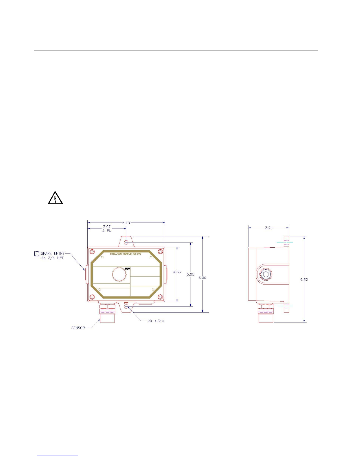
Figure 1: Ultima MOS-5 Intelligent Sensor Outline and Mounting Dimensions, in inches ..................................... 1
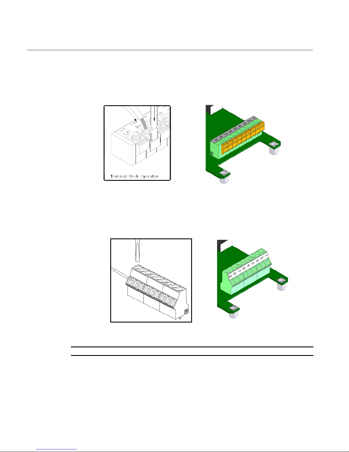
Figure 2: Spring Type Terminal Block Operation ................................................................................................... 2
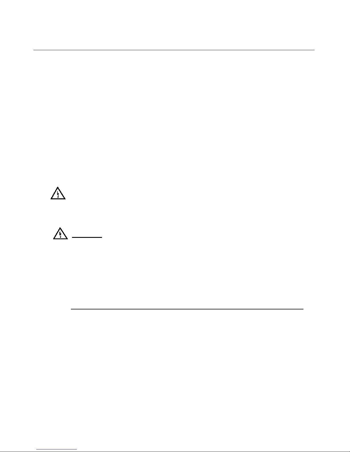
Figure 3: Screw Type Terminal Block Operation .................................................................................................... 2
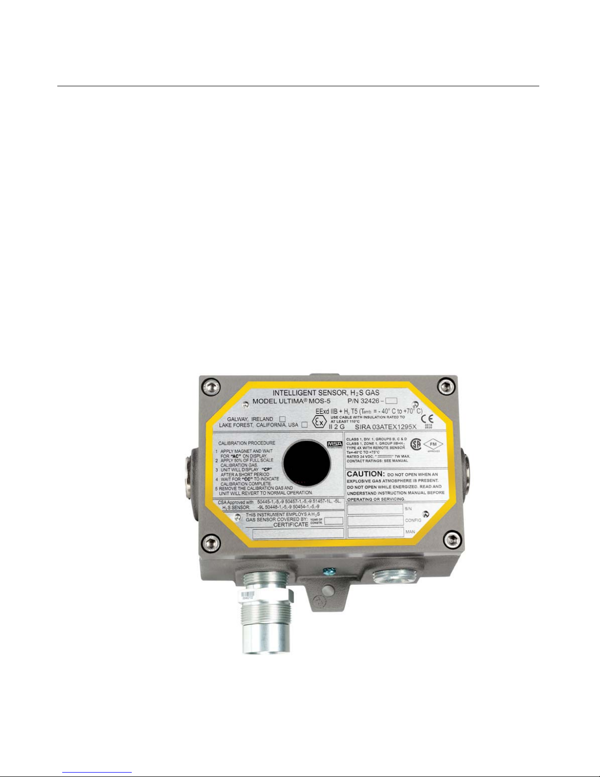
Figure 4: Ultima MOS-5 Intelligent Sensor ............................................................................................................. 7
Figure 5: Ultima MOS-5 Intelligent Sensor Outline and Mounting Dimensions, in inches ................................... 10
Figure 6: Ultima MOS-5 Intelligent Sensor Terminal Block Locations ................................................................. 11
Figure 7: Spring Type Terminal Block Operation ................................................................................................. 12
Figure 8: Screw Type Terminal Block Operation .................................................................................................. 13
Figure 9: Wire Strip Length ................................................................................................................................... 13
Figure 10: Relay Protection for DC and AC Loads ............................................................................................... 14
Figure 11: Relay Reset ......................................................................................................................................... 18
Figure 12: User Menu Structure ........................................................................................................................... 19
Figure 13: Gas Check ........................................................................................................................................... 23
Figure 14: Automatic Calibration Mode ................................................................................................................ 24
Figure 15: Calibration in Progress Mode .............................................................................................................. 24
Figure 16: Calibration Complete Mode ................................................................................................................. 25
Figure 17: Ampoules............................................................................................................................................. 26
Figure 18: Portable Purge Calibrator .................................................................................................................... 27
vi
Page 8

Ultima MOS-5 Detector
Table of Tables
Table 1: TB2 Power and Signal Connections ....................................................................................................... 12
Table 2: Alarm Relay Connections ....................................................................................................................... 14
Table 3: Warn Relay Connections ........................................................................................................................ 14
Table 4: Fault Relay Connections ........................................................................................................................ 14
Table 5: MSA Contact Information ....................................................................................................................... 32
Table 6: Data Format ............................................................................................................................................ 33
Table 7: Exception Codes .................................................................................................................................... 37
Table 8: Command Register Locations ................................................................................................................ 40
Table 9: Com1 Baud Rate .................................................................................................................................... 45
Table 10: Com1 Data Format ............................................................................................................................... 45
Table 11: Com2 Baud Rate .................................................................................................................................. 45
Table 12: Com2 Data Format ............................................................................................................................... 46
Table 13: Sensor Scale ........................................................................................................ ................................ 46
Table 14: 24 VDC Cable Lengths ......................................................................................................................... 56
Table 15: Analog Output Cable Lengths .............................................................................................................. 56
Table 16: Sensor Cable Lengths .......................................................................................................................... 56
vii
Page 9
Ultima MOS-5 Detector
Quick Start Guide
Mounting and Wiring
Tools Required
• “5mm” Allen head wrench to remove enclosure lid (included with gas detector).
• Flat-head screwdriver maximum 3/16 in (5 mm) width for terminal block (not inclu ded).
• Adjustable wrench for conduit or cable gland connections (not inclu ded).
The outline and mounting dimensions for the Ultima MOS-5 Intelligent Sensor (Figure 1) should
be used when making installation determinations.
Information on Class I Division 1 and Zone 1 wiring methods can be found in the NEC and
CEC.
WARNING: Acetic acid will cause damage to metal components, metal hardware, ceramic
IC’s, etc. If damage results from the use of a sealant that outgases acetic acid
(RTV silicone), the warranty will be void.
Figure 1: Ultima MOS-5 Intelligent Sensor Outline and Mounting Dimensions, in inches
Terminal Connections
The terminal blocks (TB) are located inside the housing and can be accessed by removing the
cover. A label inside of the housing cover provides a diagram of all the terminal connections.
It is recommended that a minimum three-wire shielded cable be used for making the power and
0-20mA Output connection on TB2 of the Ultima MOS-5 Intelligent Sensor. It is also
recommended that separate two-wire shielded twisted pair cables be used for making the
Modbus connections. The spring type terminal block accepts 14 AWG to 20 AWG and the
1
Page 10
Ultima MOS-5 Detector
screw type terminal block accepts 12 AWG to 18 AWG stranded or solid wire. Each wire should
be stripped before wiring the Ultima MOS-5 Intelligent Sensor. To connect wiring to the spring
type terminal block, insert a screwdriver into the orange tab and press down (Figure 2), opening
the terminal. Insert the wire into the terminal and release the orange tab, clamping the wire in
the terminal. Check the hold of the wire by gently tugging it to ensure it is locked in.
Figure 2: Spring Type Terminal Block Operation
To connect wiring to the screw type terminal block, loosen the top screw counter clock wise
(Figure 3). Insert the wire into the terminal and tighten the top screw clockwise.
Figure 3: Screw Type Terminal Block Operation
NOTE: Power must remain disconnecte d until all other wiring connections have been made.
The maximum distance between the Ultima MOS-5 Intelligent Sensor and the power supply is
2,000 feet or 610 meters (each cable run should be as short as possible). See Section 9.3.3 for
cable length specifications.
Connect +24 VDC to TB2, position 9. Connect the ground or common wire to TB2, position 8.
For making power and ground connections to display devices, see Figures 2 and 3.
To connect the analog signal, please refer to Section 3.5.4.
2
Page 11

Ultima MOS-5 Detector
MSA recommends that the Ultima MOS-5 Intelligent Sensor be calibrated 1 hour after start-up
and that the calibration be checked at least every 90 days to ensure system integrity.
The instrument is now ready to operate. Please consult the manual for more information on the
instrument’s many features.
NOTE: If in case of device failure during set-up or testing, please consult Troubleshooting
(Sec. 6.0) or call the factory.
3
Page 12
Ultima MOS-5 Detector
1.0 Introduction
1.1 Protection for Life
MSA’s mission is to benefit society by providing solutions through industry leading safety
products, services, and systems that save lives and protect capital resources from the dangers
of hazardous flames, gases, and vapors.
This manual provides instruction for installing and operating the Ultima MOS-5 Intelligent
Sensor for hydrogen sulfide gas detection. Although the Ultima MOS-5 Intelligent Sensor is
easy to install and operate, this manual should be read in full and the information contained
herein understood before attempting to place the system in service.
The safety products you have purchased should be handled carefully and installed, calibrated,
and maintained in accordance with the respective product instruction manual. Remember these
products are for your safety.
1.2 Special Warnings
The Ultima MOS-5 Intelligent Sensor contains components, which can be damaged by static
electricity. Special care must be taken when wiring the system to ensure that only the
connection points are touched.
WARNING: Hydrogen sulfide (H
loss of consciousness or death.
S) is an extremely toxic gas, and exposure may result in a
2
DO NOT OPEN WHEN AN EXPLOSIVE ATMOSHPERE IS PRESENT.
READ AND UNDERSTAND INSTRUCTION MANUAL BEFORE
OPERATING OR SERVICING. OPEN CIRCUIT BEFORE REMOVING
COVER.
NE PAS OUVRIR UN PRÉSENCE D’ATMOSPHÉRE EXPLOSIVE. LIRE
ET COMPRENDRE MANUEL D’INSTRUCTIONS AVANT D’UTILISER OU
SERVICE. OUVRIR LE CIRCUIT AVANT D'ENLEVER LE COUVERCLE.
SPECIAL CONDITIONS OF SAFE USE PERTAINING TO ATEX/IECEx INSTALLATIONS:
The Ultima MOS-5 shall not be used as a Safety Related Device as defined by ATEX Directive
94/9/EC,
When alternative detector elements are utilized, they shall only be mounted remotely in a
suitable certified enclosure in accordance with requirements of their respective certificates and
relevant local requirements. The associated cable shall be connected to the Intelligent Gas
Sensors using a suitably certified cable entry device with a ¾” thread form.
The Universal Gas Sensor (P/N 51457-XX) is suitable for use with the following enclosure
types and service temperature ranges that are dependent on the type of cement used in their
construction; therefore, they shall only be used with the enclosure type and where the surface
temperature, at the point of mounting, is as detailed below:
4
Page 13

Ultima MOS-5 Detector
Cement Ambient Range Enclosure Type
2850FT Cat 11
or 2762 Cat 17
2850FT Cat 11 -40°C to +120°C Enclosures that are certified by a notified body and
2762 Cat 17 -40°C to +180°C Enclosures that are certified by a notified body and
-40°C to +70°C Enclosures that are certified by a notified body and
satisfy the requirements of the current edition of EN
60079-1 or EN 60079-7 and European Directive
94/9/EC.
satisfy the requirements of the current edition of EN
60079-7 and European Directive 94/9/EC.
satisfy the requirements of the current edition of EN
60079-7 and European Directive 94/9/EC.
1.3 System Integrity Verification
To ensure operation at optimum performance, MSA recommends that certain maintenance
items be performed.
Commissioning Safety Systems
Before power-up, verify wiring, terminal connections and stability of mounting for all integral
safety equipment including the following items:
• Power supplies
• Control modules
• Field detection devices
• Signaling and output devices
• Accessories connected to field and signaling devices
After the initial application of power (and any factory specified warm-up period) to the safety
system, verify that all signal outputs, to and from devices and modules, are within the
manufacturers’ specifications. Initial calibration, calibration checking, or testing should be
performed per the manufacturer’s recommendations and instructio ns.
Proper system operation should be verified by performing a full, functional test of all component
devices of the safety system, ensuring that the proper levels of alarming occur.
Fault and malfunction circuit operation should be verified.
Periodic Testing/Calibration of Field Devices
Periodic testing/calibrating should be performed per the manufacturer’s recommendations and
instructions. Testing/Calibrating procedures should include, verify integrity of all optical surfaces
and devices
5
Page 14

Ultima MOS-5 Detector
When testing produces results outside of the manufacturer’s specifications, re-calibration or
repair and replacement of the suspect device(s) should be performed as necessary. Calibration
intervals should be independently established through a documented procedure, including a
calibration log, maintained by plant personnel or third party testing services.
Periodic System Verification
The following system verifications should be performed at least annually:
Verify wiring, terminal connections and stability of mounting for all integral safety equipment
including, the following items:
• Power supplies
• Control modules
• Field detection devices
• Signaling and output devices
• Accessories connected to field and signaling devices
Calibration intervals should be independently established through a documented procedure,
including a calibration log maintained by plant personnel or third party testing services.
6
Page 15
Ultima MOS-5 Detector
2.0 Product Description
2.1 General Description
The Ultima MOS-5 Intelligent Sensor is for the detection of hydrogen sulfide (H2S) gas. The
microprocessor-based electronics process information at the sensor site within an explosionproof housing.
A digital display provides indications and display codes that can be viewed through a window in
the cover. A red LED above the digital display signifies an “alarm” condition, while a red LED
below the digital display signifies a “warning” condition. Analog signal (4-20 mA) and relays
provide remote and/or discrete indications of the sensor’s operation. Optional dual redundant
Modbus, HART, or HART and single Modbus provide digital communication.
The Ultima MOS-5 Intelligent Sensor is rated explosion-proof for use in the following hazardous
areas:
• CSA/FM: Class I, Division 1, Groups B, C, D and Class I, Zone 1, IIB+H
• ATEX/IECEx: Zone 1, Group IIB + H
2
2
7
Figure 4: Ultima MOS-5 Intelligent Sensor
Page 16

Ultima MOS-5 Detector
3.0 Installation
3.1 Receipt of Equipment
All equipment shipped by MSA is pre-packed in shock absorbing containers, which provide
protection against physical damage (original containers should be kept for future shipping or
storage needs).
Shipping container contents should be carefully removed and checked against the packing list.
If any damage has occurred or there is any discrepancy in the order, please notify MSA as
soon as possible.
All correspondence with MSA must specify the equipment part number and serial number.
Although the factory tests each unit, a complete system checkout is suggested upon initial
installation to ensure system integrity.
WARNING: Only suitably skilled and competent personnel should carry out installation and
maintenance.
WARNING: The Ultima MOS-5 Intelligent Sensor contains components, which can be
damaged by static electricity. Special care must be taken when wiring the system to ensure that
only the connection points are touched.
3.2 Tools Required
• “5mm” Allen head wrench to remove enclosure lid (included with gas detector).
• Flat-head screwdriver maximum 3/16 in (5 mm) width for terminal block connections
(not included).
• Adjustable wrench for conduit or cable gland connections (not inclu ded).
3.3 Choosing Product Locations
There are no standard rules for sensor placement, since the optimum sensor location is
different for each application. The customer must evaluate conditions at the facility to make this
determination. In generally, experience suggests the device is more effective at detecting gas if
the following recommendations are followed:
• Mount sensor pointing down to prevent water build-up on the sensor head.
• Do not place sensor where contaminating substances may coat it.
• Although the Ultima MOS-5 Intelligent Sensor is RFI resistant, do not install sensor in
close proximity to radio transmitters or similar equipment.
• Locate the Ultima MOS-5 Intelligent Sensor where prevailing air currents contain the
maximum concentration of gas.
• Locate the Ultima MOS-5 Intelligent Sensor near possible sources of gas leaks.
8
Page 17

Ultima MOS-5 Detector
• Observe the Ultima MOS-5 Intelligent Sensor temperature specification and locate the
unit away from concentrated sources of heat.
• Install sensor in an area that is as free from wind, dust, water, shock, and vibration as
possible. See Section 0 for the environmental specifications of the unit. If dust and rain
cannot be avoided, we recommend the use of our splash guard (P/N 10395-1).
Sensors may be adversely affected by prolonged exposure to certain substances. Loss of
sensitivity or corrosion may be gradual if such agents are present in low concentrations or it
may be rapid at high concentrations. Examples of these substances are as follows:
• Silicones (often contained in greases and aerosols)
• Halides: compounds containing fluorine, chlorine, bromine and iodine
• Heavy metals, e.g. tetraethyl lead
• Caustic and Acidic liquids and vapors
• Glycol
The presence of contaminants in an area does not necessarily preclude the use of an Ultima
MOS-5 Intelligent Sensor. The feasibility of using a sensor in such areas must be determined
by an analysis of the specific factors in each application, and MSA should be consulted before
attempting any such installation.
Sensors used in these areas usually require more frequent calibration checks than normal, and
typically have a shorter life. In many such applications the standard 2-year warranty would not
apply.
IMPORTANT: Each H
Inside the cap is a desiccant. Do not remove this cap until the system is ready
to be powered. Save the cap and re-cap the sensor anytime the system power
is off for more than 1 hour.
WARNING: MSA discourages the painting of sensor assemblies. If the sensor head is
painted over, the gas will not be able to diffuse into the sensor. If the assembly
cover is painted over, the digital display cannot be read.
S sensor is shipped with a red plastic cap fitted over the sensor head.
2
3.3.1 Remote Mounting of the Sensor from the Electronics
If it is necessary to remotely mount the sensor from the electronics and the housing, the
maximum distance can be no greater than 3,700 feet (1,125) meters, using 14 AWG wire.
Sensors that are remotely mounted must be placed in an explosion-proof rated sensor
housing (P/N 10252-1), and the cable run must be contained in a conduit running from the
sensor housing to the electronics.
For remote mounting in Canada where the location is classified using the Zone classification
system, the sensors must be mounted in sensor housing B14-020. Only sensors 51457 can
be used in this configuration.
9
Page 18

Ultima MOS-5 Detector
3.4 Mounting and Wiring
WARNING: Unused cable entry holes must be sealed with an approved explosion-proof plug.
Red caps supplied by MSA are for dust protection only and must not be left on the
unit when installed.
WARNING: Conduits must be sealed within 18 inches of the enclosure.
The outline and mounting dimensions for the Ultima MOS-5 Intelligent Sensor (Figure 5) should
be used when making installation determinations. A complete list of the mechanical
specifications can be found in Section 9.3.2.
To prevent possible corrosion due to moisture or condensation, the conduit connected to the
Ultima MOS-5 Intelligent Sensor housing should be sealed or contain a drain loop.
NOTE: For ATEX and IECEx applications, conduit connections must only be made via suitably
certified ATEX (or IECEx as appropriate) conduit stopping boxes.
Information on Class I Division 1 and Zone 1 wiring methods can be found in the NEC or CEC.
Figure 5: Ultima MOS-5 Intelligent Sensor Outline and Mounting Dimensions, in inches
WARNING: Acetic acid will cause damage to metal components, metal hardware, ceramic
IC’s and other parts. If damage results from the use of a sealant that outgases
acetic acid (RTV silicone), the warranty will be void.
Once correctly installed, the Ultima MOS-5 Intelligent Sensor requires little or no maintenance,
other than periodic calibration checks to ensure system integrity. MSA recommends that a
schedule be established and followed.
10
Page 19
Ultima MOS-5 Detector
NOTE: The Ultima MOS-5 Intelligent Sensor full 2-year warranty will be voided if customer
personnel or third parties damage the Ultima MOS-5 Intelligent Sensor during repair
attempts.
Sensor heads exposed to the elements may require the accessory mounting threads to be
lubricated. Grease must not be used. As an alternate, PTFE (Teflon) tape may be used on
sensor accessory threads.
NOTE: Do not use any material or substance on threads that contact the sensor housing.
The removal of particulate matter from sensor accessories may be done through the use of an
appropriate halogen-free solvent. Water or ethanol is an example of a suitable solvent. The
accessories should be thoroughly dried, with compressed air if necessary, before refitting to the
sensor body.
3.5 Terminal Connections
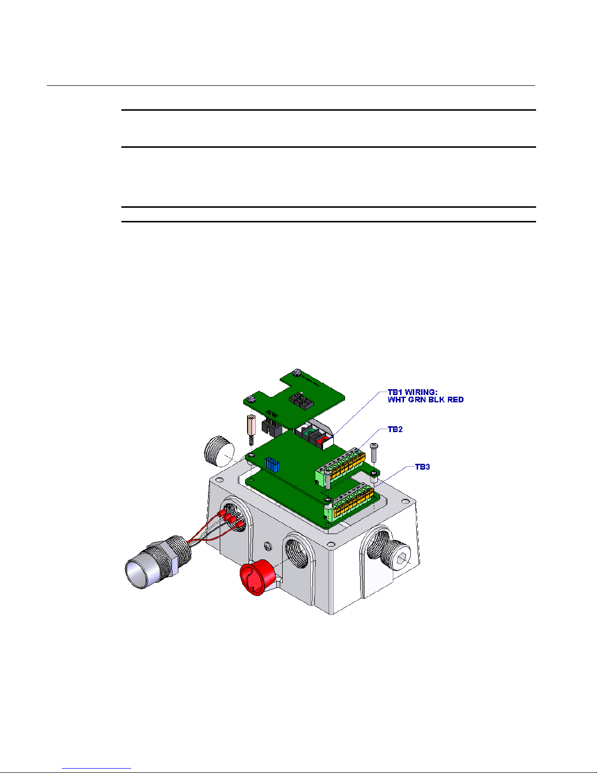
The terminal blocks (TB) are located inside the housing and can be accessed by removing the
cover. A label on the inside of the housing cover provides details of all the terminal
connections.
Figure 6: Ultima MOS-5 Intelligent Sensor Terminal Block Locations
3.5.1 Terminal Block TB1 – Sensor Connections
TB1 contains the four sensor connections, white (W), black (B), red (R) and green (G). Remove
the display board by loosening the 2 captive screws on the board and lifting it straight up.
Connect the color-coded wires from the sensor to the matching colored terminals on TB1. The
11
Page 20
Ultima MOS-5 Detector
label on the inside of the cover can serve as a guide. Replace the display board by pressing it
into place and tightening the two captive screws.
WARNING: Do not connect +24 VDC to TB1. Damage to electronics or sensor may result.
3.5.2 Terminal Block TB2 – Power and Signal Connections
TB2 contains the connections for Power, Relay Reset, Remote Calibration, Modbus, and 0-20
mA Output Signal. The terminal connections are as follows:
TB2 position Function
1 0-20 mA Output
2 CH1 Modbus 3 CH1 Modbus +
4 CH2 Modbus 5 CH2 Modbus +
6 Remote Calibration
7 Relay Reset
8 Ground
9 +24 VDC Power
Table 1: TB2 Power and Signal Connections
It is recommended that a minimum three-wire shielded cable be used for making the power and
0-20mA Output connection on the Ultima MOS-5 Intelligent Sensor. It is also recommended
that separate two-wire shielded twisted pair cables be used for making the Modbus
connections. The spring type terminal block accepts 14 AWG to 20 AWG and the screw type
terminal block accepts 12 AWG to 18 AWG stranded or solid wire. Each wire should be
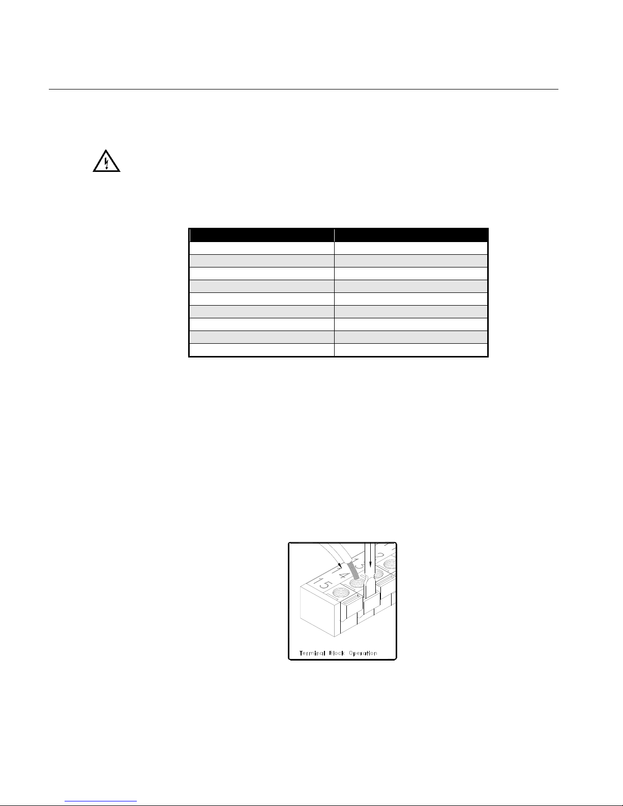
stripped before wiring the Ultima MOS-5 Intelligent Sensor. To connect wiring to the spring type
terminal block, insert a screwdriver into the orange tab and press down (Figure 7). Insert the
wire into the terminal and release the orange tab, clamping the wire in the terminal. Check the
hold of the wire by gently tugging it to ensure it is locked in. To connect wiring to the screw type
terminal block, loosen the top screw counterclockwise (Figure 8). Insert the wire into the
terminal and tighten the top screw clockwise. Check the hold of the wire by gently tugging it to
ensure it is locked in.
12
Figure 7: Spring Type Terminal Block Operation
Page 21
Ultima MOS-5 Detector
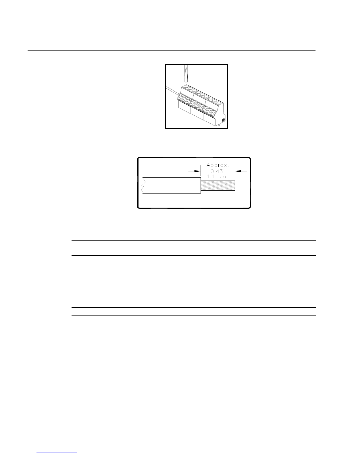
Figure 8: Screw Type Terminal Block Operation
Figure 9: Wire Strip Length
NOTE: Up to 12 AWG wire can be used if it is carefully striped. This applies only to a screw
type terminal connection (Figure 8).
3.5.3 DC Power and Ground Connections
• The customer must provide primary DC power.
Since the Ultima MOS-5 Intelligent Sensor is designed to operate continuously, a power switch
is not included, in order to prevent accidental system shutdown.
NOTE: Power must remain disconnected until all other wiring connections have been made.
See Section 9.3.3 for cable length specifications.
To connect +24 VDC to the Ultima MOS-5 Intelligent Sensor, connect the red wire (+24 VDC)
to TB2, position 9. Connect the ground or common wire to TB2, position 8.
3.5.4 Analog Signal Connections
The Ultima MOS-5 Intelligent Sensor Intelligent Transmitter provides a 4 to 20 mA output
signal. This signal can be sent to an industrial analog to digital converter, or logic solver.
The 4 to 20 mA signal provides for control room or other locations remote to the Ultima MOS-5
Intelligent Sensor to display indications of operation and alarm conditions.
To connect the 4 to 20 mA output signal with another unit, connect the wire into TB2, position 1,
labeled 4-20 mA OUT.
13
Page 22

Ultima MOS-5 Detector
If a readout device is being used, the DC ground, COM of both systems must be connected
together. The analog output can also be configured as a HART communication link.
3.5.5 Terminal Block TB3 – Relay Connections
TB3 contains the connections for the relay contacts (optional). The function for the warn and
alarm relay connections vary according to the normal state of the relay. Use the following as a
guide for determining the Normally Open (NO) and the Normally Closed (NC) contact:
TB3 position Relay Contact (De-Energized) Relay Contact (Energized)
1 Normally Closed Normally Open
2 Common Common
3 Normally Open Normally Closed
Table 2: Alarm Relay Connections
TB3 position Relay Contact (De-Energized) Relay Contact (Energized)
4 Normally Closed Normally Open
5 Common Common
6 Normally Open Normally Closed
Table 3: Warn Relay Connections
TB3 position Relay Contact (Energized)
7 Normally Open
8 Common
9 Normally Closed
Table 4: Fault Relay Connections
NOTE: Fault relay is normally energized. Relay will change state after power up.
WARNING: Contact with PCB components should be avoided to prevent damage by static
electricity. All wire connections are made to the Terminal Blocks.
WARNING: Relay contacts must be protected against transient and over voltage conditions
(Figure 10).
14
Figure 10: Relay Protection for DC and AC Loads
Page 23

Ultima MOS-5 Detector
North American Approved Applications - The alarm relay contact ratings are 8 A @ 250 VAC
and 8 A @ 30 VDC resistive max.
European Union (EU) Approved Applications - The alarm relay contact ratings are 8 A, 30 V
RMS/42.4 V peak or 8 A @ 30 VDC resistive max.
3.5.6 European Union (EU) Approved Applications
Interconnecting cables must have an overall screen, or screen and armor. Cables BS5308 Part
2, Type 2, or equivalent, are suitable. Note that the terms ‘screen’ and ‘shield’ are equivalent for
the purpose of this manual. The cable armor must be terminated in a suitable cable gland, at
the detector, to ensure a positive electrical connection.
3.5.7 Cable Termination in the Non-hazardous Area
• The cable armor must be connected to safety earth in the safe area.
• The cable screen (drain wire) must be connected to an instrument earth in the safe
area.
• The power supply OV return must be connected to an instrument earth in the safe
area.
• The interconnecting cables should be segregated from power and other noisy cables.
Avoid proximity to cables associated with radio transmitters, welders, switch mode
power supplies, inverters, battery chargers, ignition systems, generators, switch gear,
arc lights, and other high frequency or high power switching process equipment. In
general, a minimum separation of at least 1 meter between instrument and other
cables should be maintained. Greater separations are required where long parallel
cable runs are unavoidable. Avoid running instrument cable trenches close to lightning
conductor earth pits.
• Complete all cable insulation testing before connecting the cable at either end.
WARNING: Under NO circumstances should equipment be connected or disconnected when
under power. This is contrary to hazardous area regulations and may lead to
serious damage to the equipment. Equipment damaged in this manner is not
covered under warranty.
3.6 Maintaining the X/P Integrity
Some of the factors that influence the explosion-proof integrity of the Ultima MOS-5 Intelligent
Sensor housing are:
• Strength of the enclosure material
• Thickness of the enclosure walls
• Flame path between the housing and cover
• Flame path of threaded joints
The acceptable limits for explosion-proof housings that are used in Class I hazardous locations
are defined in CSA Standard C22.2 No.30-M1986, FM 3615, and EN50014.
15
Page 24

Ultima MOS-5 Detector
Anytime the cover of the Ultima MOS-5 Intelligent Sensor housing is removed or the cover bolts
are loosened, the flame path between the lid and the housing is affected. If power is to be left
on while removing the cover or loosening the cover bolts on the Ultima MOS-5 Intelligent
Sensor, the area must be declassified.
When replacing the cover, the gap between the lid and the housing should be less than 0.0015
inch (0.038 mm). Make sure that the flame path is clear of dirt and debris before replacing the
cover. This can be verified by tightening the cover bolts to a torque setting of 50 inch-pounds or
by using a feeler gauge to ensure the gap between the cover and the housing is less than
0.0015 inch (0.038 mm).
There are four entry holes, one each on the left and right sides, and two on the bottom of the
Ultima MOS-5 Intelligent Sensor housing. These holes are dedicated for the sensor, the reset
switch, and conduit. Each hole is tapped for ¾” NPT threads. If a particular entry hole is not
used, it must be plugged during operation in the field. The factory installs plugs in the unused
entry holes, except one. A red plastic cap is placed into the remaining hole and must be
removed before conduit can be attached to the housing.
The Ultima MOS-5 Intelligent Sensor will have the following items placed in the three remaining
entry holes, at the factory:
• A sensor, if present (otherwise a red plastic cap)
• A reset switch, if present (otherwise an aluminum housing plug – optional)
• An aluminum housing plug
The sensor, reset switch, and aluminum - housing plug have 7 threads. Each of these
components is screwed into the housing using 5 to 7 turns. If any of these parts must be
replaced, apply 5 to 7 turns upon replacing the component to ensure the explosion proof
integrity of the device is maintained.
16
Page 25

Ultima MOS-5 Detector
4.0 Operation
4.1 Start-Up Checklist
Prior to starting the system, verify the following:
• Inhibit any external devices, such as trip amplifiers, PLC, or DCS systems.
• Verify that the optional settings are set for the desired configuration.
• Verify that the unit is properly mounted. Ensure the conduit/cable gland entries are
pointed downward.
• Verify that the signal wiring is correct.
• Verify that the power supply is connected properly. The Ultima MOS-5 Intelligent
Sensor is powered by +24 VDC (20 to 36 VDC voltage range). The detector will output
a low voltage fault (F6) at 18.5 VDC or below.
• Make sure the lid is securely installed or the area has been declassified.
• Make sure the HART option is selected if desired.
• Make sure Modbus is properly configured if desired.
4.2 Start-Up
Before applying power to the system for the first time, all wiring connections should be checked
for correctness and the housing cover replaced. Upon first power-up, the sensor may take up to
fifteen minutes to stabilize.
At the initial application of power, the unit test all LED segments by displaying “88.8”. The
software revision letter is then displayed for a few seconds. When the software revision level
appeared, the unit enters Operational Mode and the current ga s concentration at the sensor will
be displayed. For details on Calibrating and Gas Checking the unit, see Sections 4.56 and 4.7.
4.3 Relay Reset
If the warn and alarm relays are configured as latching, they must be manually reset after an
alarm occurs. This can be accomplished by three different methods:
• The relays can be reset by using a magnet. To do this, place the magnet over the MSA
logo on the cover of the unit. After 3 seconds, the display shows “rSt”. After the LED
displayed this code, remove the magnet. The relays are now reset (Figure 11).
17
Page 26

Ultima MOS-5 Detector
Figure 11: Relay Reset
• The relays can be reset via the remote reset input terminals on TB2. Connect a
normally open switch between terminal TB2-7 and TB2-8. Closing the switch
momentarily will reset the relays. MSA explosion-proof switch, P/N 30051-1 can be
used for this purpose. See Section 9.5 for ordering instructions.
• The relays can be reset via the Modbus Interface (Section 8.8.22).
• The relays can be reset via the HART communication.
NOTE: Red LEDs above and below the digital display indicate that the alarm and warn relays
are active. Latching relays can only be reset if the gas concentration has fallen below
the respective relay set point.
4.4 User Selectable Options
The Ultima MOS-5 Intelligent Sensor includes many selectable options to provide the user with
the most flexible H
warn and alarm relay set points and configuration, HART communications and Modbus
communications settings. These allow the unit to operate with a wide variety of PLC and DCS
systems. The following sections explain the available options and how they can be customized.
A flow diagram is included to help the user in understanding the process of reviewing and
changing the available options (Figure 12).
NOTE: If the unit was ordered without relays, HART, or Modbus communications, changing the
relay, HART, or Modbus settings will have no effect on the operation of the unit.
Modbus
• Dual Redundant Modbus
• Single Modbus and HART
HART
• HART is a Master to Slave -One to One communication channel.
S gas detector possible. These options include selectable sensor range,
2
18
Page 27

Ultima MOS-5 Detector
4.4.1 Ultima MOS-5 Intelligent Sensor User Menu Structure
Operate
Rm
“rSt”
Reset
Relays
Hm HmHm
Rm
Enter Gas Check Mode
“- -”
Rm
“AC”
Rm
Enter Calibration
Mode
Hm
“SE” Time Out
Rm
Am
“Sr”
Set Sensor Range
20,50,100 ppm
“SE”
Hm
N
“Fi”
Y
Fault
N
Hm – Hold magnet
Am – Apply magnet
Rm – Remove magnet
N – No
Y - Yes
Gas
Detected?
Y
Gas
Removed?
Reset Sensor
Life?
Am
Reset Sensor Life
to 100%
Apply Gas and
Remove When
Complete
If Hart Enabled
N
N
N
Am
“Co”
Y
If Hart installed
Y
“Hrt” Enable Disable
“Lo”
Warm Relay
“Hi”
Alarm Relay
“CH1”
Modbus Ch. 1
If Hart Enabled
N
“CH2”
Modbus Ch. 2
Y
“Fi”
Finished
Enable Disable
Am
Am
Energized or
De-Energized
Am
Energized or
De-Energized
Am
Baud
Rate
Am
Baud
Rate
Am
Latching or
Non-Latching
Latching or
Non-Latching
Data
Format
Data
Format
“Fi”
“Fi”
Address
Address
Setpoint
Setpoint
“Fi”
“Fi”
“Fi”
“Fi”
NOTE: “Co” stands for Calibration Output. When “Co” is enabled and calibration is
successful, the analog output goes from 1.5 mA to 3.2 mA for five seconds, settling
at the desired value of 4 mA. This option is commonly used with the MSA Model
10000 Controller system.
4.4.2 Sensor Range
The sensor range is selectable between 0-20 ppm, 0-50 ppm, or 0-100 ppm depending on the
installed sensor. To adjust the sensor range of the Ultima MOS-5 Intelligent Sensor, apply the
magnet to the MSA logo on the cover of the unit until “SE” is displayed, then remove the
magnet. This puts the unit into setup mode. After a few seconds “Sr” will be displayed. Apply
and remove the magnet to adjust the sensor range. The current sensor range will be displayed.
To change the sensor range, apply and remove the magnet repeatedly until the desired range
is displayed. Once the desired range is displayed, wait three seconds and “Fi” will be displayed.
19
Figure 12: User Menu Structure
Page 28

Ultima MOS-5 Detector
Apply and remove the magnet, to return to the next level of the setup menu. When “Fi” is
displayed again, apply and remove the magnet, the unit will go to calibration mode. The display
will flash the remaining sensor life for a few seconds. Ensure that the sensor is seeing clean air
during this time. Apply the calibration gas concentration to the sensor (50% FS of the desired
range of H
Calibration) to “CP” (Calibration in Progress) indicating that the sensor is responding to the
calibration gas.
After 3 to 5 minutes, the display will change from “CP” to “CC”, indicating that the
calibration is complete. Remove the gas and wait for the unit to return to normal operation. The
unit is now calibrated and the new span value has been stored in the non-volatile memory
(EEPROM). If a fault occurs during this process, please refer to the notes section below.
NOTE: When the sensor range is changed, the warning and alarm set points are automatically
It is recommended to go back through the SE mode to confirm range and sensor set-
2S. *See notes section below.). The display will change from “AC” (Automatic
scaled to the new range. The unit must now be calibrated to the new range (Section
4.7.1). The Sensor Range and the Alarm/Warning set points will remain at the previous
setting if the calibration is aborted, faulted, or the power is cycled before the calibration
is completed.
points have been changed correctly. Changing the sensor range will require that the
operator change the H2S concentration previously used for calibrating the unit. It is
necessary to use 50% of the "new" full scale reading when changing the scale, as well
as after the scale is changed during normal calibration maintenance periods (i.e.
10ppm for a 0-20ppm, 25ppm for a 0-50ppm and 50ppm for a 0-100ppm). It is
important to note that changing a unit’s range may require changing the sensor
to match the new sensor range. (-1 sensor for 0-100 ppm, -5 sensor for 0-50 ppm,
and -9 for 0-20 ppm).
Once the operator reaches the calibration mode, the operator will have 12 minutes to complete
a calibration. If the 12 minute timeframe elapses and the calibration is not complete (unit must
return to "0" reading for calibration to be considered complete), the unit's display will show an
"F2" fault. If this occurs while changing the Sensor Range, the operator must start the Sensor
Range process over until the process is completed properly without any faults being shown
throughout the process. If faults continue during this process, please consult the factory
directly.
4.4.3 Calibration Output
To enable the calibration output feature of the Ultima MOS-5 Intelligent Sensor, apply the
magnet to the MSA logo on the cover of the unit until “SE” is displayed, then remove the
magnet. This puts the unit into setup mode. After a few seconds “Co” will be displayed. Apply
and remove the magnet to enter the calibration output setting. The current setting (Enable or
Disable) will then be displayed. To change this setting, apply and remove the magnet
repeatedly until the desired setting is displayed. Once it is displayed, wait three seconds and
“Fi” will be displayed. Apply and remove the magnet to return to the next level of the setup
menu. When “Fi” is displayed again, apply and remove the magnet to return to normal
operation.
4.4.4 Warning Relay Settings
To adjust the warning relay settings of the Ultima MOS-5 Intelligent Sensor, apply the magnet
to the MSA logo on the cover of the unit until “SE” is displayed, then remove the magnet. This
20
Page 29

Ultima MOS-5 Detector
puts the unit into setup mode. After a few seconds “Lo” will be displayed. Apply and remove the
magnet to change the warning or “low” alarm settings.
First, the energized/de-energized state of the relay is shown by either “En” or “dE” being
displayed, respectively. Apply and remove the magnet until the desired state is displayed.
After a few seconds the latching/non-latching state of the relay is shown by either “La” or “nL”.
Apply and remove the magnet, until the desired state is displayed.
After a few seconds, the current warning relay set point is displayed. Apply and remove the
magnet, until the desired set point is displayed. Once the desired set point value is displayed,
wait 3 seconds and “Fi” will be displayed. Apply and remove the magnet to return to the next
level of the Setup menu. When “Fi” is displayed again, apply and remove the magnet to return
to normal operation.
The default warning relay settings are non-latching, de-energized, 30% FS set point. The
maximum allowable set point is 50 ppm.
NOTE: The warn relay set point cannot be set higher than the alarm relay set point.
4.4.5 Alarm Relay Settings
To adjust the alarm relay settings of the Ultima MOS-5 Intelligent Sensor, apply the magnet to
the MSA logo on the cover of the unit until “SE” is displayed, then remove the magnet. This
puts the unit into setup mode. After a few seconds “Hi” will be displayed. Apply and remove the
magnet, to change the alarm or “high” alarm settings.
First, the energized/de-energized state of the relay is displayed by either “En” or “dE” being
displayed respectively. Apply and remove the magnet, until the desired state is displayed.
After a few seconds the latching/non-latching state of the relay is displayed by either “La” or
“nL”. Apply and remove the magnet until the desired state is displayed.
After a few seconds the current Alarm relay set point is displayed. Apply and remove the
magnet until the desired set point is displayed. Once the desired set point value is shown, wait
3 seconds and “Fi” will be displayed. Apply and remove the magnet to return to the next level of
the setup menu. When “Fi” is displayed again, apply and remove the magnet, to return to
normal operation.
The default Alarm relay settings are: latching, de-energized, 60% FS set point.
NOTE: The alarm relay set point cannot be set lower than the Warning relay set point.
4.4.6 Modbus Channel 1 Settings
To change the Modbus Channel 1 settings of the Ultima MOS-5 Intelligent Sensor, apply the
magnet to the MSA logo on the cover of the unit until “SE” is displayed, then remove the
magnet. This puts the unit into setup mode. After a few seconds “CH1” will be displayed. Apply
and remove the magnet to change the Modbus Channel 1 settings.
21
Page 30

Ultima MOS-5 Detector
First, the current Baud Rate Modbus Channel 1 is displayed. If another baud rate is to be
selected, apply and remove the magnet until the desired baud rate is displayed. The choices
are 19.2k baud “19.2”, 9600 baud “96”, 4800 baud “48”, or 2400 baud “24”.
After a few seconds, the current Data Format for Modbus Channel 1 is displayed. If another
data format is to be selected, apply and remove the magnet until the desired data format is
displayed. The choices are: 8-N-1 “8n1”, 8-N-2 “8n2”, 8-E-1 “8E1”, or 8-O-1 “8O1”.
After a few seconds, the current address for Modbus Channel 1 is displayed. Apply and
remove the magnet until the desired address is displayed. Once the desired address is
displayed, wait for 3 seconds and “Fi” will be displayed. Apply and remove the magnet to
return to the next level of the Setup menu. When “Fi” is displayed again, apply and remove the
magnet to return to normal operation.
Default settings for Channel 1 are: address 1, 19.2k baud, 8-N-1.
NOTE: The address can be adjusted from 1 to 247. Channel 1 and Channel 2 addresses may
be the same.
4.4.7 Modbus Channel 2 Settings
NOTE: If HART is enabled the Modbus 2 settings do not appear on the display. To use Modbus
2 make sure HART is disabled.
To change the Modbus channel 2 settings, apply the magnet to the MSA logo and set the unit
in set up mode. Once “CH2” is displayed, follow the same steps as in section 4.4.5 above.
Default settings for Channel 2 are: address 2, 19.2k baud, 8-N-1.
NOTE: The address can be adjusted from 1 to 247. Channel 1 and Channel 2 addresses may
be the same.
4.5 HART
This option is not shown if HART was not purchased for the Ultima MOS-5 Intelligent Sensor.
When HART is selected via setup, the Channel 2 setup is not displayed or available. When
Channel 2 is changed from HART to Modbus, the previous settings are used.
To change the HART setting of the Ultima MOS-5 Intelligent Sensor, apply the magnet to the
MSA logo on the cover of the unit until “SE” is displayed, then remove the magnet. This puts
the unit into setup mode. After a few seconds “Hrt” will be displayed. Apply and remove the
magnet to enter the HART setting. The current setting (Enable or Disable) will then be
displayed. To change this setting, apply and remove the magnet repeatedly until the desired
setting is displayed. Once it is displayed, wait three seconds and “Fi” will be displayed. Apply
and remove the magnet to return to the next level of the setup menu. When “Fi” is displayed
again, apply and remove the magnet to return to normal operation.
The Ultima MOS-5 Intelligent Sensor has a HART option. The HART option allows the user to
get management information and to remotely calibrate the unit. Because HART preserves the
4-20 mA signal, it enables two-way digital communication to occur without disturbing the
22
Page 31

Ultima MOS-5 Detector
integrity of the analog connection. The DDL is available at the HART foundation’s website
(http://www.hartcomm2.org/index.html). If the Ultima MOS-5 Intelligent Sensor is ordered with
the HART option it is in the enabled state. The HART function can also be disabled and then
Channel 2 can be used for Modbus.
The Ultima MOS-5 Intelligent Sensor HART configuration is compatible with the Emerson 375
Field Communicator and AMS Aware. http://www.emersonprocess.com/
http://www.emersonprocess.com/ams/
4.6 Gas Check Mode
The sensor’s response can be checked without activating external alarms by placing the Ultima
MOS-5 Intelligent Sensor in Gas Check Mode. In this mode, the alarm relays are inhibited and
the analog output is fixed at 1.5 mA. Please see section 9.3.3 for more information on the
analog output values.
NOTE: If HART is enabled, the current may be different. See HART analog output selection
chart.
4.6.1 Procedure for Checking the Calibration
Place the magnet over the MSA logo on the cover of the Ultima MOS-5 Intelligent Sensor.
Remove the magnet when a flashing pair of bars, “- -” appears on the display (about 10
seconds) (Figure 13). Apply the test gas to the sensor. The value of the gas concentration will
be indicated by the flashing display and should stabilize in 1 to 2 minutes.
Figure 13: Gas Check
When the reading has stabilized and the test is complete, remove the gas and the unit will
return to normal operation, when the concentration drops below 5% full-scale.
If, after the reading has stabilized, the sensor is to be calibrated, simply apply the magnet to the
MSA logo on the housing cover and the unit will enter Calibration Mode.
Gas Check Mode can be aborted if gas has not been applied to the sensor. Simply reapply the
magnet to the MSA logo on the cover and the unit will return to normal operation.
NOTE: The test gas concentration must be at least 10% full-scale before the unit will complete
the gas check sequence. If the Ultima MOS-5 Intelligent Sensor is placed in the gas
check mode and no gas is applied for twelve minutes, the unit will revert to a Fault
condition. Re-applying the magnet over the MSA logo will return the unit to normal
operation.
23
Page 32

Ultima MOS-5 Detector
4.7 Calibration
MSA recommends that the Ultima MOS-5 Intelligent Sensor be calibrated 1 hour after start-up,
and again 24 hours after initial start-up, and that the calibration be checked at least every 90
days to ensure system integrity of this life protecting equipment.
The above statement is not intended to discourage the customer from checking calibration
more frequently. Frequent calibration checks are recommended for environments that have
problems, such as mud collecting on the sensor head, sensors accidentally being painted over,
etc.
MSA recommends that a calibration schedule be established and followed. A logbook should
also be kept, showing calibration dates and dates of sensor replacement.
4.7.1 Calibration Procedure
If hydrogen sulfide (H2S) gas is suspected to be present, it will be necessary to purge the
sensor environment with clean air.
Entering Calibration Mode automatically disables the alarm circuits by sending a 1.5 mA output
signal and disabling the warn and alarm relays, if present. This will also prevent activation of
the remote relay contacts when using an MSA readout/relay display module with the Ultima
MOS-5 Intelligent Sensor. Please see section 9.3.3 for more information on the analog output
values.
To enter Calibration Mode, place the magnet over the MSA logo on the cover of the unit (Figure
4) and hold it there until “AC” (Figure 14) appears on the display (about 10 seconds). The
display will flash the remaining sensor life (Section 4.7.3) for a few seconds. Ensure that the
sensor is seeing clean air during this time.
Figure 14: Automatic Calibration Mode
Apply the calibration gas concentration to the sensor (50% FS of the desired range of H
The display will change from “AC” (Automatic Calibration) to “CP” (Calibration in Progress)
indicating that the sensor is responding to the calibration gas (Figure 15).
S).
2
24
Figure 15: Calibration in Progress Mode
Page 33

Ultima MOS-5 Detector
After 3 to 5 minutes, the display will change from “CP” to “CC” indicating that the calibration is
complete. (Figure 16).
Figure 16: Calibration Complete Mode
Remove the gas and wait for the unit to return to normal operation. Once the gas concentration
decreases, the display will read a few percent LEL and then will reach “0.”
The unit is now calibrated and the new span value has been stored in the non-volatile memory
(EEPROM).
NOTE: The sensor life figure displayed is that calculated on completion of the last calibration.
To determine the current sensor life, calibrate unit and then repeat steps 1 and 2.
4.7.2 Aborting Calibration
If calibration is to be aborted and gas has not been applied, wait ninety seconds and reapply
the magnet. The unit will then returns to normal operation with the previous calibration values
unchanged.
NOTE: Once gas has been applied, it is not possible to abort a calibration.
If the Ultima MOS-5 Intelligent Sensor is placed in the Calibration Mode and no gas is applied
for 12 minutes, the unit reverts to a Fault (F2) condition. Re-applying the magnet over the MSA
logo returns the unit to operational mode with the previous calibration values unchanged.
4.7.3 Remaining Sensor Life
The Ultima MOS-5 Intelligent Sensor provides an estimate of remaining sensor life, in percent
remaining, to provide the user with an early warning of the need for sensor replacement. The
remaining sensor life is updated each time the unit is calibrated. The current remaining sensor
life estimate is displayed during the zeroing portion of a calibration sequence. It can also be
read via the Modbus or HART interface (Section 8.0).
NOTE: Remaining sensor life is an estimate of sensor degradation derived from sensor
sensitivity. Because sensor sensitivity is affected by factors other than the natural
sensor degradation, users must establish their own reference by resetting sensor life
whenever these factors are at play. Some examples of these factors are new sensor
installations, sensor replacement, change of the target gas, and changes in the access
of gas to the sensor. If sensor life is not reset, the remaining sensor life indicator will
no longer reflect the true state of the sensor.
25
Page 34

Ultima MOS-5 Detector
4.7.4 Initializing the Remaining Sensor Life
The remaining sensor life estimate must be initialized each time a new hydrogen sulfide sensor
is installed. The initialization should be done during the first calibration of a newly installed
sensor. After the sensor has been on power for a minimum of 1 hour, enter calibration mode as
described in Section 4.7. While the display is flashing the remaining sensor life estimate during
zeroing, apply the magnet to the MSA logo on the cover. The flashing number will change to
“100”, indicating the sensor has 100% of remaining sensor life. Complete the calibration per
Section 4.7.1.
4.8 Calibration Equipment
4.8.1 Calibrating with a Breaker Bottle and Ampoules
MSA offers ampoules with breaker bottles as a method of reliably introducing calibration gas to
the Ultima MOS-5 Intelligent Sensor. The ampoule is placed inside the breaker bottle into the
breaker slot, and the breaker bottle is placed over the sensor. The ampoule should contain
50% FS of H
display indicates “AC”, break the ampoule by turning the thumbscrew on the side of the breaker
bottle clockwise. The display will change to “CP” indicating that the sensor is seeing the gas.
When the display reads “CC”, the calibration is complete. Remove the breaker bottle and allow
the sensor to see clean air. It will return to normal operation once the gas at the sensor is below
5% of full-scale. See Section 9.5 for available equipment.
S of the sensor range. Follow the calibration procedure in Section 4.7. When the
2
4.8.2 Calibrating with an H2S Portable Purge Calibrator
An alternate method for introducing calibration or test gas to the Ultima MOS-5 Intelligent
Sensor is available. The H
safe system for field calibration of H
in air mixture and is available in seven concentrations. The temperature limitation for operation
and storage is 0°F to +130°F (-18°C to +54°C).
26
Figure 17: Ampoules
S Portable Purge Calibrator is a compact, practical, accurate and
2
S sensors. The bottle is filled with a hydrogen sulfide (H2S)
2
Page 35

Ultima MOS-5 Detector
Figure 18: Portable Purge Calibrator
NOTE: Do not store the cylinder with the regulator fully engaged in the cylinder valve.
To calibrate, make sure the portable purge calibrator contains a gas concentration equivalent to
50% of full-scale for the unit that is going to be calibrated. Ensure that the sensor is seeing
clean air. If it is suspected that hydrogen sulfide gas is present, it will be necessary to purge the
sensor environment with clean air.
Place the gas cup over the sensor and initiate the calibration sequence, by placing the magnet
over the MSA logo on the cover of the unit. When the letters “AC” appear in the display
window, remove the magnet and apply the calibration gas (50% of full-scale) by opening the
valve on the cylinder. When the sensor begins to see the gas, the display will change from “AC”
to “CP” to indicate “Calibration in Progress”. When the calibration sequence is complete, the
display will change from “CP” to “CC” to indicate “Calibration Complete”.
Remove the gas by closing the valve on the cylinder, and remove the cup allowing the sensor
to see clean air. The display will change from “CC” to indicate a few parts per million (ppm) and
then drop to “0”. The unit is now calibrated and the new values have been stored in the
EEPROM (non-volatile memory). See Section 9.5 for available equipment.
27
Page 36

Ultima MOS-5 Detector
5.0 Maintenance
5.1 General Maintenance
WARNING: Disconnect or inhibit external devices such as trip amplifiers, PLC’s, or DCS
systems before performing any maintenance.
European Union (EU) Approved Applications: The following grease compound is recommended
for use: PBC Polybutylcuprysil, (or equivalent), which has BASEEFA Health & Safety Executive
Component Approval No. 1051U for use as a jointing compound on flameproof electrical
enclosures. This is available from MSA.
The neoprene rubber gasket should also be lubricated with Type P80 lubricant, available from
MSA (P/N 610-010).
5.2 Storage
The Ultima MOS-5 Intelligent Sensor should be stored in a clean, dry area and within the
temperature and humidity ranges quoted in the Appendix under Environmental Specifications.
Insert red dust caps into any vacant cable entry holes. See section 9.3.4.
28
Page 37

Ultima MOS-5 Detector
6.0 Troubleshooting
CAUTION: Component level repair must be undertaken by MSA personnel or by competent
authorized service engineers. SMT PCB repair shall only be performed at an MSA
facility. Failure to comply with this requirement will invalidate the warranty.
Be sure to inhibit or disconnect external alarm wiring before making any check, which might
send the unit into alarm.
6.1 Fault Codes and Their Remedies
The Ultima MOS-5 Intelligent Sensor has self-diagnostics incorporated into the
microprocessor’s program. If a fault is detected, the output signal drops to 0 mA, the fault relay
de-energizes and a fault code is displayed. The output signal informs a remote display module
that the Ultima MOS-5 Intelligent Sensor is in the Fault Mode. The display indicates a fault code
that can be viewed at the sensor site. Refer to section 9.3.3 for more information on analog
output values.
There are nine fault conditions that are monitored by the microprocessor as follows:
6.1.1 F2 - Failed to Complete the Calibration
This fault occurs if the unit is placed in the calibration mode and no gas is applied within twelve
minutes, or if gas is left on for more than twelve minutes.
ACTION - Remove gas, if present. Apply magnet to MSA logo on the cover to clear fault. Re-
calibrate, if necessary.
6.1.2 F3 Flash Checksum Error
This fault indicates that the contents of the Ultima MOS-5 Intelligent Sensor’s program memory
have changed. This usually occurs when powering the unit up after a lightning strike or large
voltage transient on the power or signal lines to the unit.
ACTION - The unit must be returned to the factory or authorized service center for repair.
6.1.3 F4 - Sensor Heater Open Error or Sensor Amplifier Error
This fault indicates that either one of the remote sensor leads is open or shorted or that the
sensor has drifted greater than –10% of the reading. The Ultima MOS-5 Intelligent Sensor has
an additional protection feature. If any of the sensor wires are shorted to ground, the sensor
power is turned off. After one minute the power turns back on. If the short is still present, power
is quickly turned off.
ACTION - Check the integrity of all sensor connections, and ensure that the cable from the
Ultima MOS-5 Intelligent Sensor to the remote sensor is not damaged. If all sensor
leads are connected properly, attempt to re-calibrate the unit. If calibration fails,
replace the sensor and re-calibrate.
NOTE: Anytime a sensor is replaced, the unit should be disconnected from all alarms as the
unit may go upscale upon power-up.
29
Page 38

Ultima MOS-5 Detector
If this does not solve the problem the internal sensor amplifier has a defective part. The unit
must be returned for service.
6.1.4 F5 - Sensor Heater Shorted Error
This fault indicates that one of the sensor circuit leads is short-circuited to ground or +24 V.
ACTION - Check the integrity of all sensor connections and ensure that the cable from the
Ultima MOS-5 Intelligent Sensor to the remote sensor is not damaged. If this does
not correct the problem, replace the sensor and recalibrate.
NOTE: When the black lead is accidentally shorted to +24 Volts, the Ultima MOS-5 Intelligent
Sensor delays coming out of fault to allow parts to cool down.
6.1.5 F6 - Low Supply Voltage
This fault occurs if the supply voltage at the Ultima MOS-5 Intelligent Sensor drops below +18.5
VDC.
ACTION - Ensure that the supply voltage is at least +20 VDC at the Ultima MOS-5 Intelligent
Sensor.
NOTE: With long supply leads, a considerable voltage drop may occur due to the electrical
resistance of the leads. The maximum cable resistance, which the Ultima MOS-5
Intelligent Sensor can tolerate, is dependent on the supply voltage.
6.1.6 F7 - EEPROM Verification Failure
In the event of an EEPROM error, the user must recycle the power to potentially clear the error.
After power reset, the following may occur:
1) Unit returns to normal.
a. This indicates the EEPROM writing did not keep up with changing events or the
Modbus write cycle is too fast.
2) Unit goes to F2. The user must recalibrate after 1-2 minute sensor warm up.
a. This means the non-critical part of the EEPROM was corrupted.
b. This is probably caused by an event-logging problem.
c. There is a possibility any of the following may be corrupted:
i. Event logging data
ii. Modbus settings
iii. HART Settings
iv. Calibration information
3) Unit returns to F7
a. This is a critical error. This fault occurs when an attempt to verify the
setup/calibration parameters just written to the EEPROM memory fails.
ACTION - The unit must be returned to the factory or authorized service center for repair.
6.1.7 F8 - Failure to Complete Setup
This fault occurs if the unit is left in setup mode for more than six minutes.
30
Page 39

Ultima MOS-5 Detector
ACTION - Exit setup mode. Enter setup mode again to change any user selectable options, if
necessary.
6.1.8 F9 - Gas Check Period Exceeded
If the Ultima MOS-5 Intelligent Sensor is left in the Gas Check Mode for more than 12 minutes
with test gas applied, this fault occurs.
ACTION - Place the magnet over the MSA logo on the cover to return the unit to normal
operation.
NOTE: Anytime a sensor is replaced, the unit should be disconnected from all alarms, as the
unit may go upscale upon power-up.
6.1.9 F10 – Switch Error
This fault occurs if either the “remote test,” “remote calibrate,” or magnetic switch is closed for
more than two minutes.
ACTION – Check the wiring on the remote reset and remote calibrate switches. Once the short
circuit is cleared, the unit will return to normal operation. If the magnetic switch is shorted, the
unit must be returned to the factory or to an authorized service center for service.
6.1.10 F11 Internal Error
An internal error has occurred.
ACTION - The unit must be returned to the factory for service. A possible error is that internal
voltages are not at their proper values. Different options will have different internal
errors.
31
Page 40

Ultima MOS-5 Detector
7.0 Customer Support
7.1 MSA Office
Address Phone/Email
Mine Safety Appliances Co.
26776 Simpatica Circle
Lake Forest, CA 92630
MSA Corporate
1000 Cranberry Woods Drive
Cranberry Twp, PA 16066
United States
MSA Europe
Thiemannstrasse 1
12059 Berlin
Germany
Additional MSA office locations can be found on our website –
Toll Free: 1-800-MSA-INST
Email: customer.service@msanet.com
Toll Free: 1-800-MSA-7777
Email: customer.service@MSAnet.com
Phone: +49 [30] 68 86 0
Fax: +49 [30] 68 86 15 58
Email: info.de@MSAsafety.com
www.MSAsafety.com
Table 5: MSA Contact Information
32
Page 41

Ultima MOS-5 Detector
8.0 Modbus Interface
8.1 Baud Rate
The baud rate is selectable via the Modbus Communications Interface. The selectable baud
rates are 19200, 9600, 4800, or 2400 bits per second.
8.2 Data Format
The Data Format is selectable via the Modbus Communications Interface. The selectable data
formats are as follows:
Data Bits Parity Stop Bit Format
8 None 1 8-N-1
8 Even 1 8-E-1
8 Odd 1 8-O-1
8 None 2 8-N-2
Table 6: Data Format
8.3 Modbus Read Status Protocol (Query/Response)
8.3.1 Modbus Read Query Message
Byte Modbus Range Referenced to Ultima MOS-5
Intelligent Sensor
1st Slave Address 1-247* (Decimal) Ultima MOS-5 Intelligent Sensor ID
(Address)
2nd Function Code 03 Read Holding Registers
3rd Starting Address Hi** 00 Not Used by Ultima MOS-5
Intelligent Sensor
4th Starting Address Lo** 00-FF (Hex) Ultima MOS-5 Intelligent Sensor
Commands
5th No. Of Registers Hi 00 Not Used by Ultima MOS-5
Intelligent Sensor
6th No. Of Registers Lo 01 No. Of 16 Bit Registers
7th CRC Lo 00-FF (Hex) CRC Lo Byte
8th CRC Hi 00-FF (Hex) CRC Hi Byte
*NOTE: Address 0 is reserved for broadcast mode and will not be supported at this time.
** NOTE: Start Address can be a maximum of 9999 Address Locations (0000-270E).
33
Page 42

Ultima MOS-5 Detector
8.3.2 Modbus Read Response Message
Byte Modbus Range Referenced to Ultima MOS-5
Intelligent Sensor
1st Slave Address 1-247* (Decim al) Ultima MOS-5 Intelligent Sensor ID
(Address)
2nd Function Code 03 Read Holding Registers
3rd Byte Count 02 No. Of Data Bytes
4th Data Hi 00-FF (Hex) Ultima MOS-5 Intelligent Sensor Hi
Byte Status Data
5th Data Lo 00-FF (Hex) Ultima MOS-5 Intelligent Sensor Lo
Byte Status Data
6th CRC Lo 00-FF (Hex) CRC Lo Byte
7th CRC Hi 00-FF (Hex) CRC Hi Byte
34
Page 43

Ultima MOS-5 Detector
8.4 Modbus Write Command Protocol (Query/Response)
8.4.1 Modbus Write Query Message
Byte Modbus Range Referenced to Ultima MOS-5
Intelligent Sensor
1st Slave Address 1-247* (Decimal) Ultima MOS-5 Intelligent Sensor ID
(Address)
2nd Function Code 06 Preset Single Register
3rd Register Address Hi 00 Not Used by Ultima MOS-5
Intelligent Sensor
4th Register Address Lo 00-FF (Hex) Ultima MOS-5 Intelligent Sensor
Commands
5th Preset Data Hi 00-FF (Hex)
6th Preset Data Lo 00-FF (Hex)
7th CRC Lo 00-FF (Hex) CRC Lo Byte
8th CRC Hi 00-FF (Hex) CRC Hi By te
Ultima MOS-5 Intelligent Sensor Hi Byte
Command Data
Ultima MOS-5 Intelligent Sensor Lo Byte
Command Data
*NOTE: Address 0 is reserved for broadcast mode and will not be supported at this time.
**NOTE: Start Address can be a maximum of 9999 Address Locations (0000-270E).
8.4.2 Modbus Write Response Message
Byte Modbus Range Referenced to Ultima MOS-5
Intelligent Sensor
1st Slave Address 1-247* (Decimal) Ultima MOS-5 Intelligent Sensor ID
(Address)
2nd Function Code 06 Preset Single Register
3rd Register Address Hi 00 Not Used by Ultima MOS-5
Intelligent Sensor
4th Register Address Lo 00-FF (Hex) Ultima MOS-5 Intelligent Sensor
Commands
5th Preset Data Hi 00-FF (Hex)
6th Preset Data Lo 00-FF (Hex)
7th CRC Lo 00-FF (Hex) CRC Lo Byte
8th CRC Hi 00-FF (Hex) CRC Hi By te
Ultima MOS-5 Intelligent Sensor Hi Byte
Command Data
Ultima MOS-5 Intelligent Sensor Lo Byte
Command Data
35
Page 44

Ultima MOS-5 Detector
8.5 Function Codes Supported
Function Code 03 (Read Holding Registers) is used to read status from the slave unit.
Function Code 06 (Preset Single Register) is used to write a command to the slav e unit.
8.6 Exception Responses and Exception Codes
8.6.1 Exception Response
In a normal communications query and response, the master device sends a query to the
Ultima MOS-5 Intelligent Sensor and the Ultima MOS-5 Intelligent Sensor receives the query
without a communications error and handles the query normally within the master device’s
allowable timeout. The Ultima MOS-5 Intelligent Sensor then returns a normal response to
the master. An abnormal communications produces one of four possible events:
• If the Ultima MOS-5 Intelligent Sensor does not receive the query due to a
communications error, then no response is returned from the Ultima MOS-5 Intelligent
Sensor and the master device eventually processes a timeout condition for the query.
• If the Ultima MOS-5 Intelligent Sensor receives the query, but detects a communication
error (CRC, etc.), then no response is returned from the Ultima MOS-5 Intelligent
Sensor and the master device eventually processes a timeout condition for the query.
• If the Ultima MOS-5 Intelligent Sensor receives the query without a communications
error, but cannot process the response to the master within the master’s timeout
setting, then no response is returned from the Ultima MOS-5 Intelligent Sensor. The
master device eventually processes a timeout condition for the query. In order to
prevent this condition from occurring, the maximum response time for the Ultima MOS5 Intelligent Sensor is 200 milliseconds. Therefore, the master’s timeout setting should
be set to 200 milliseconds or greater.
• If the Ultima MOS-5 Intelligent Sensor receives the query without a communications
error, but cannot process it due to reading or writing to a non-existent Ultima MOS-5
Intelligent Sensor command register, then the Ultima MOS-5 Intelligent Sensor returns
an exception response message informing the master of the error.
The exception response message (ref. No. 4 above) has two fields that differentiate it from a
normal response:
Byte Modbus Range Referenced to Ultima MOS-5
Intelligent Sensor
1st Slave Address 1-247* (Decimal) Ultima MOS-5 Intelligent Sensor ID
(Address)
2nd Function Code 83 or 86 (Hex)
3rd Exception Code 01 - 06 (Hex)
4th CRC Lo 00-FF (Hex) CRC Lo Byte
5th CRC Hi 00-FF (Hex) CRC Hi Byte
MSB is set with Function Code
Appropriate Exception Code (See Below)
36
Page 45

Ultima MOS-5 Detector
8.6.2 Exception Code
Exception Code Field: In a normal response, the Ultima MOS-5 Intelligent Sensor returns
data and status in the data field, which was requested in the query from the master. In an
exception response, the Ultima MOS-5 Intelligent Sensor returns an exception code in the data
field, which describes the Ultima MOS-5 Intelligent Sensor condition that caused the exception.
Below is a list of exception codes that are supported by the Ultima MOS-5 Intelligent Sensor:
Code Name Description
The function code received in the query is not an
01 Illegal Function
02 Illegal Data Address
03 Illegal Data Value
04 Slave Device Failure
05 Acknowledge
06 Device Busy
allowable action for the Ultima MOS-5 Intelligent
Sensor
The data address received in the query is not an
allowable address for the Ultima MOS-5 Intelligent
Sensor.
A value contained in the query data field is not an
allowable value for the Ultima MOS-5 Intelligent
Sensor.
An unrecoverable error occurred while the Ultima
MOS-5 Intelligent Sensor was attempting to perform
the requested action.
The Ultima MOS-5 Intelligent Sensor has accepted
the request and is processing it, but a long duration of
time will be required to do so. This response is
returned to prevent a timeout error from occurring in
the master.
The Ultima MOS-5 Intelligent Sensor is engaged in
processing a long-duration program command. The
master should retransmit the message later when the
slave is free.
Table 7: Exception Codes
37
Page 46

Ultima MOS-5 Detector
8.7 Ultima MOS-5 Command Register Locations
Register
Parameter Function Type Scale Access
Analog 0-20 mA Current Output Value 16-Bit R 0000 40001
Mode Indicates and Controls Mode Bit R/W 0001 40002
Status/Error Indicates Errors Bit R 0002 40003
Not Used N/A 0003 40004
Unit Type Identifies the Ultima MOS-5
Intelligent Sensor in Decimal
Software Rev Indicates the Software Revision ASCII 2-Char R 0005 40006
Status Block Returns Analog, Mode, Status,
Error, and Sensor Life Returns
Address 6,7,8
Analog Analog 2 Value R 0006 40007
Mode Mode Bit R 0006 40007
Error 2 Error 2 Bit R 0007 40008
Error 1 Error 1 Bit R 0007 40008
Sensor Life Sensor Life Value R 0008 40009
Display Display (LED & MSD) Bit
Display Display (Mid & LSD) ASCII R 000A 40011
Serial Number Upper serial number Value R 000B 40012
Serial Number Lower serial number 32 bit R 000C 40013
Alarm Settings Read or change settings for the
high alarm
Warn Settings Read or change settings for the
low alarm
Com1 Addr. Read or change settings for the
Com1 Address
Com1 Baud Read or change settings for the
Com1 Baud Rate
Com1 Data
Format
Com2 Addr. Read or change settings for the
Com2 Baud Read or change settings for the
Com2 Data
Format
Not Used N/A 0015 40022
Reset Alarms Reset any latched alarms Bit (0) W 0016 40023
Sensor Life Read the Remaining Sensor
Sensor Scale Change the Scale for the H2S
MODEL 10K
Controller (Co)
Not Used 001A 40027
Not Used 001B 40028
Read or change settings for the
Com1 Data Format
Com2 Address
Com2 Baud Rate
Read or change settings for the
Com2 Data Format
Life
sensors on the Ultima MOS-5
Intelligent Sensor
Indicates Calibration Success Value 8-Bit R/W 0019 40026
Value 16-Bit R 0004 40005
Multi 6-bytes R 0006 40007
R 0009 40010
/ASCII
Bit (0-15) R/W 000D 40014
Bit (0-15) R/W 000E 40015
Value 8-Bit R/W 000F 40016
Bit (0-7) R/W 0010 40017
Bit (0-7) R/W 0011 40018
Value 8-Bit R/W 0012 40019
Bit (0-7) R/W 0013 40020
Bit (0-7) R/W 0014 40021
Bit (0) R 0017 40024
Value 8-Bit R/W 0018 40025
Address
Master I/O
Address
38
Page 47

Ultima MOS-5 Detector
Register
Parameter Function Type Scale Access
Not Used 001C 40029
HART EN/DE Enable/Disable Bit 1/0 R/W 001D 40030
HART Test Transmit a constant 1 or 0
signal
Cal Abort Abort calibration R/W 001F 40032
Total Receive
Errors
Bus Activity
Rate %
Function Code
Errors
Starting Addr.
Errors
No. of
Register
Errors
RXD CRC Hi
Errors
RXD CRC
Low Errors
Ch1 Parity
Errors
Ch1 Overrun
errors
Ch1 Framing
errors
Ch1 Software
Errors
Not used 002B 40044
Clear CH1
Errors
Clear Ch1
Errors
HART Ao
Range
Not used Internal use only 002F 40048
Event Timer Event Set Time Hi 0030 40049
Event Timer Event Set Time Lo 0031 40050
Clear Event 005F 40096
User Info User information 1 0060 40097
User Info User information 2 0061 40098
“ “”
“
User info User information 16 006F 40112
Ch2 Total
Receive
Errors
Total # of Receive Errors Value 8-Bit R 0020 40033
Bus Activity Rate in % of This
Addressed Node vs. Other
Addressed Nodes
Total # of Function Code Errors Value 8-Bit R 0022 40035
Total # of Starting Address
Errors
Total # of Register Errors Value 16-Bit R 0024 40037
Total # of RXD CRC Hi Errors Value 16-Bit R 0025 40038
Total # of RXD CRC Low Errors
Same as 38
Total parity errors Value 16-Bit R 0027 40040
Total overrun errors Value 16-Bit R 0028 40041
Total Framing errors Value 16-Bit R 0029 40042
Total Software request errors Value 16-Bit R 002A 40043
Clear Ch1 Hardware Errors Bit (0) W 002C 40045
Clear Ch 1 Software Errors Bit (0) W 002D 40046
Changes the range of Ao for
HART only
See Event CHART
Total # of Receive Errors Value 16-Bit R 0070 40113
Value 0,1,2 R/W 001E 40031
Decimal R 0021 40034
Value 8-Bit R 0023 40036
Value 16-Bit R 0026 40039
R/W 002E 40047
Address
Master I/O
Address
39
Page 48

Ultima MOS-5 Detector
Register
Parameter Function Type Scale Access
Ch2 Bus
Activity Rate
%
Ch2 Function
Code Errors
Ch2 Starting
Addr Errors
Ch2 No of
Register
Errors
Ch2 CRC errors Value 16-Bit R 0075 40118
Ch2 CRC errors Value 16-Bit R 0076 40119
Ch2 Parity
Errors
Ch2 Overrun
errors
Ch2 Framing
errors
Ch2 Software
Errors
Not used Not used 007B 40124
Ch2 Clear
errors
Ch2 Clear
errors
Not used Not used 007E 40127
Bus Activity Rate in % of This
Addressed Node vs. Other
Addressed Nodes
Total # of Function Code Errors Value 16-Bit R 0072 40115
Total # of Starting Address
Errors
Total # of Register Errors Value 16-Bit R 0074 40117
Total parity errors Value 16-Bit R 0077 40120
Total overrun errors Value 16-Bit R 0078 40121
Total Framing errors Value 16-Bit R 0079 40122
Total Ch 2 Software request
errors
Ch2 Clear Hardware errors Bit 0 R/W 007C 40125
Ch2 Clear Software errors Bit 0 R/W 007D 40126
Decimal R 0071 40114
Value 16-Bit R 0073 40116
Value 16-Bit R 007A 40123
Address
Master I/O
Address
Table 8: Command Register Locations
40
Page 49

Ultima MOS-5 Detector
8.8 Ultima MOS-5 Command Register Details
8.8.1 Analog (00H)
A read returns a value, which is proportional to the 0-20 mA output current. The current is
based on a 16-bit value. The scaling is 0 - 65535 decimal, which corresponds to 0 - 21.7 mA.
8.8.2 Mode (01H)
A read returns the present mode of the Ultima MOS-5 Intelligent Sensor.
A write command changes the mode to the requested mode. A data value of 08 starts
calibration mode if the unit is in the run mode. It also goes from cal check to cal mode.
Exception: Returns an exception code 01 (illegal function) if an illegal write is requested.
A calibrate command returns an exception code 01 (Acknowledge 05). The operation will take
a long time to complete.
Function Bit Position Access
Calibration Complete 7 MSB Read
Spanning 6 Read
Zero Complete, Waiting for Gas 5 Read
Zeroing 4 Read
Calibration Mode 3 Read/Write
Calibration Check Mode 2 Read/Write
Run Mode 1 Read
Startup Mode 0 LSB Read
8.8.3 Status/Error (02H)
A read returns the alarm state and errors that are occurring at the present time, which are
indicated, by bit position.
Function Bit Position Access
Alarm 15 MSB Read
Warn 14 Read
Fault 13 Read
Not Used 12 Read
Not Used 11 Read
Not Used 10 Read
Not Used 9 Read
Switch Error 8 Read
Setup Error 7 Read
Calibration Check Timeout 6 Read
EEPROM Error 5 Read
EPROM Error 4 Read
Sensor Error 3 Read
Fail to Calibrate 2 Read
Low Supply Voltage 1 Read
41
Page 50

Ultima MOS-5 Detector
8.8.4 Not Used (03H)
8.8.5 Unit Type (04H)
A read returns the decimal value 4005. This identifies the Ultima MOS-5 Intelligent Sensor.
8.8.6 Software Revision (05H)
A read returns the software revision of the Ultima MOS-5 Intelligent Sensor in 2 ASCII
characters.
8.8.7 Status Block (06H)
A read returns a 6-byte message containing the analog (2 bytes), mode (1 byte), status/error
(2 bytes), and sensor life (1 byte) in that order. For the format of each byte, refer to the
appropriate individual commands.
NOTE: These registers can be read individually or as a group. Only when the starting address
is 06 is a block return.
8.8.8 Analog Value (06H)
A value which is proportional to the 0-20 mA output current. The current is based on a 16-bit
value. The scaling is 0 - 65535 decimal, which corresponds to 0 - 21.7 mA.
8.8.9 Mode & Error (07H)
See mode (02)
Calibration Complete 8000
Spanning 4000
Zero Complete, Waiting for Gas 2000
Zeroing 1000
Calibration Mode 0800
Calibration Check Mode 0400
Run Mode 0200
Startup Mode
Alarm
Warn
Error ( any error)
NA
NA
NA
Internal
Switch
0100
0080
0040
0020
0010
0008
0004
0002
0001
8.8.10 Error Sensor & Sensor Life (08H)
8.8.10.1 Upper Bit for Sensor Errors
Setup error 80
Cal Check error 40
EEPROM Check sum error 20
Flash Check sum 10
42
Page 51

Ultima MOS-5 Detector
Sensor 08
Calibration error 04
Low supply 02
NA 01
8.8.10.2 Lower Bit for Sensor Life
Sensor Life 0-100%
8.8.11 Display (0x09H & 0x0AH)
The display is also present on the Modbus. It is at address 0x09 and 0x0A. The first address
(0x09) contains the LED, the decimal point location, and the most significant digit (MSD). The
upper word represents the LED and Decimal point. They are defined as shown below. The
lower word is the ASCII value for the MSD. The second address (0x0A) represents the middle
digit (MID) and the least significant digit (LSD) in ASCII. The upper word represents the MID
and the lower word represents the LSD.
DP_LSD 0x01
DP_MID 0x02
DP_MSD 0x04
WRN_LED 0x08
ALM_LED 0x10
8.8.12 Serial Number (0BH/0CH)
The serial number is a 32-bit word but the value is only 23 bits long. The upper bits are
always zero. This is done to keep the same serial number as the HART serial number.
Address 0x0C contains the lower part of the number and address 0X0B contains the upper
part.
8.8.13 Alarm Settings (0DH)
A read returns the present alarm settings of the Ultima MOS-5 Intelligent Sensor. A write
command changes the settings to the requested values. The set points are programmable in
5% FS steps (1% FS steps for 20 ppm range).
NOTE: The maximum alarm setting for the Ultima MOS-5 Intelligent Sensor is 60% LEL.
A “1” in the 9th bit position means the output is latching, a “0” means it is non-latching. A “1” in
th
the 8
bit position means the output is normally energized a “0” means it is normally de-
energized. The alarm set point cannot be set below the warn set point.
Factory default is 60% FS, latching, de-energized.
Exception: Returns an exception code 01 (illegal function) if an illegal write is requested.
43
Page 52

Ultima MOS-5 Detector
Byte Function Bit Position Access
High Not Used 15 MSB Read
Not Used 14 Read
Not Used 13 Read
Not Used 12 Read
Not Used 11 Read
Not Used 10 Read
Latching/Non-Latching 9 R/W
Energized/De-Energized 8 R/W
Low Set point (7-0) R/W
8.8.14 Warn Settings (0EH)
A read returns the present warn settings of the Ultima MOS-5 Intelligent Sensor. A write
command changes the settings to the requested values. The set points are programmable in
5% FS steps (1% FS steps for 20 ppm range).
NOTE: The maximum alarm setting for the Ultima MOS-5 Intelligent Sensor is 60% LEL.
A “1” in the 9th bit position means the output is latching, a “0” means it is non-latching. A “1” in
th
the 8
bit position means the output is normally energized a “0” means it is normally de-
energized. The warn set point cannot be set above the alarm set point.
Factory default is 30% FS, non-latching, de-energized. The maximum allowable set
point is 50 ppm.
Exception: Returns an Exception Code 01 (illegal function) if an illegal write is requested.
Byte Function Bit Position Access
High Not Used 15 MSB Read
Not Used 14 Read
Not Used 13 Read
Not Used 12 Read
Not Used 11 Read
Not Used 10 Read
Latching/Non-Latching 9 R/W
Energized/De-Energized 8 R/W
Low Set point (7-0) R/W
8.8.15 Com1 Address (0FH)
A read command returns the current address for Com1. A write command changes the
address to the requested value. Valid addresses are 1-247 decimal. Factory default is 1.
Exception: If the address is not in range an illegal data value (03) is returned.
8.8.16 Com1 Baud Rate (10H)
A read command returns the current baud rate for Com1. A write command changes the baud
rate to the requested values. Valid settings are shown in the table on the following page.
Factory default is 19200.
44
Page 53

Ultima MOS-5 Detector
Baud Rate Value Access
2400 24 Read/Write
4800 48 Read/Write
9600 96 Read/Write
19200 192 Read/Write
Table 9: Com1 Baud Rate
Exception: If the baud rate is not in range, an illegal data value (03) is returned.
8.8.17 Com1 Data Format (11H)
A read command returns the current data format for Com1. Write command changes the data
format to the requested values. Valid settings are shown in the table below. Default format is
8-N-1.
Data Parity Stop Format Data(Bits 9-8) Access
8 None 1 8-N-1 0 Read/Write
8 Even 1 8-E-1 1 Read/Write
8 Odd 1 8-O-1 2 Read/Write
8 None 2 8-N-2 3 Read/Write
Table 10: Com1 Data Format
Exception: If the data format is not in range, an illegal data value (03) is returned.
8.8.18 Com2 Address (12H)
A read command returns the current address for Com2. A write command changes the
address to the requested values. Valid addresses are 1-247 decimal. Factory default is 2.
Exception: If the address is not in range an illegal data value (03) is returned.
8.8.19 Com2 Baud Rate (13H)
A read command returns the current baud rate for Com2. A write command changes the baud
rate to the requested values. Valid settings are shown in the table below. Factory default is
19200.
Baud Rate Value Access
2400 24 Read/Write
4800 48 Read/Write
9600 96 Read/Write
19200 192 Read/Write
Table 11: Com2 Baud Rate
Exception: If the baud rate is not in range an illegal data value (03) is returned.
8.8.20 Com2 Data Format (14H)
A read command returns the current data format for Com2. Write command changes the data
format to the requested values. Valid settings are shown in the table below. Factory default is
8-N-1.
45
Page 54

Ultima MOS-5 Detector
Data Parity Stop Format Data(Bits 9-8) Access
8 None 1 8-N-1 0 Read/Write
8 Even 1 8-E-1 1 Read/Write
8 Odd 1 8-O-1 2 Read/Write
8 None 2 8-N-2 3 Read/Write
Table 12: Com2 Data Format
Exception: If the data format is not in range an illegal data value (03) is returned.
8.8.21 Not Used (15H)
8.8.22 Reset Alarms (16H)
A write to this register with a data value of 1 resets any latched alarms provided the current
gas level is below the alarm set point.
8.8.23 Sensor Life (17H)
A read returns the current estimate of remaining sensor life in percentage.
8.8.24 Sensor Scale (18H)
A read returns the current H2S sensor scale selected: 0-20 ppm, 0-50 ppm, 0-100 ppm. A
write changes the scale to the desired scale. If the scale is changed, a calibration fault is
generated, forcing the operator to calibrate the unit.
H2S Sensor Scale Value (decimal)
0-20 ppm 20
0-50 ppm 50
0 –100 ppm 100
Table 13: Sensor Scale
8.8.25 MODEL 10K Controller (Co – Calibration Output) (19H)
This register indicates when a successful calibration takes place. In MODEL 10K Controller
mode, the current goes to 3.2 mA for five seconds then to 4.0 mA. An aborted calibration
would go straight to 4.0 mA. A read to this register will return the status of the MODEL 10K
Controller option.
0x01 enables this option, 0x00 disables this option, similar to the write.
8.8.26 Not Used (1A, AB, 1C H)
8.9 HART Enable (1D H)
This command enables or disables the HART. A “0” is Modbus a “1” is HART.
8.9.1 HART Test (1Eh)
This command is used to test the HART output. It produces constant zeros or constant ones
on the HART output.
46
Page 55

Ultima MOS-5 Detector
Code Results
0 Normal
1 Constant ones
2 Constant zeros
8.9.2 Abort Calibration (1Fh)
Sending a “1” causes a calibration or calibration abort.
8.9.3 Total Receive Errors (20H)
A read indicates the total number of Modbus communication receive errors that occurred in
the slave device. When the counter for these errors reaches 255, it rolls over to zero and
begins counting again. The total errors are an accumulation of the individual communication
errors listed below.
8.9.4 Bus Activity Rate % (21H)
A read indicates the bus activity rate in percent of this Slave’s addressed node versus other
addressed nodes. Range of this value is in hex (0-64) which translates to decimal (0-100%).
8.9.5 Function Code Errors (22H)
A read indicates the number of function code errors that occurred in the slave device. When
the counter for these errors reaches 255, it rolls over to zero and begins counting again.
8.9.6 Starting Address Errors (24H)
The counter is incremented for each address that does not equal the device address.
A read indicates the number of starting address errors that occurred in the slave device. When
the counter for these errors reaches 255, it rolls over to zero and begins counting again.
8.9.7 RXD CRC Errors Hi (25H)
A read indicates the number of RXD CRC errors that occurred in the slave device. When the
counter for these errors reaches 255, it rolls over to zero and begins counting again.
8.9.8 RXD CRC Errors Lo (Same as Hi) (26H)
NOTE: Hi and Lo CRC errors are now reported in the same word. A read from either Hi or Lo
returns the same count.
8.9.9 Parity Errors (27H)
A read indicates the number of hardware UART parity errors that occurred in the slave device.
When the counter for these errors reaches 65535, it rolls over to zero and begins counting
again.
47
Page 56

Ultima MOS-5 Detector
8.9.10 Overrun Errors (28H)
A read indicates the number of hardware UART overrun errors that occurred in the slave
device. When the counter for these errors reaches 65535, it rolls over to zero and begins
counting again.
8.9.11 Framing Errors (29H)
A read indicates the number of hardware UART framing errors that occurred in the slave
device. When the counter for these errors reaches 65535, it rolls over to zero and begins
counting again.
8.9.12 Total Software CH1 Errors (2AH)
A read indicates the number of address or data errors that occurred in the slave device. When
the counter for these errors reaches 65535, it rolls over to zero and begins counting again.
8.9.13 Not Used (2BH)
8.9.14 Clear Hardware Errors (2CH)
Clear parity, framing, and overrun errors.
8.9.15 Clear Communication Errors (2DH)
8.9.15.1 HART Low Current Select (2EH)
Normally in HART mode the low current does not decrease below 3.5 mA. If use of current
levels below 3.5mA is required by an application, the Ultima MOS-5 Intelligent Sensor
features and expanded scale that permits faults to be set as low as 1.25 mA. A read returns
“1” or “0.”
Condition HART Current Normal HART Expanded Scale
Run
Off Line
Fault
4 to 20 mA 4 to 20 mA
3.5 mA 1.5 mA
3.5 mA 1.25 mA
8.9.15.2 Internal Use (2FH)
8.9.15.3 Event Logging (30H to 5FH)
Faults
• Whenever the fault word changes, the time is recorded.
• Time of fault is saved.
• The quantity of faults is saved in a counter.
• When the fault is removed, it is not saved and the counter is not incremented.
• A fault event is logged for every 30 seconds recorded.
• There are a total of ten event time stamps stored.
48
Page 57

Warning
The time the gas level reaches the warning level is recorded. Each time this happens a counter
is incremented. The end of the event is when the gas goes below 5%. The counter is also
saved. There are a total of ten event time stamps stored.
Alarm
The time where the gas level reaches the alarm level is recorded. Each time this happens a
counter is incremented. The end of the event is when the gas goes below 5%. The counter is
also saved. There are a total of ten event time stamps stored.
Calibration
The time a successful zero and calibration occurs is saved in the event log. A counter is
increment for each successful calibration. If the unit fails to zero or calibrate, the event is not
recorded. If the calibration is aborted the event is also not recorded. Note the zero and
calibration are one operation in the Ultima MOS-5 Intelligent Sensor. There are a total of ten
event time stamps stored.
Maintenance
Ultima MOS-5 Detector
The time a Check Calibration occurs is saved in the maintenance event log. Each successful
calibration increments the maintenance counter. There are a total of 10 event time stamps
stored.
Setting structure clock
See table below.
Event Logging Registry Table
Address
(hex)
30 Seconds Time Hi Seconds Time Hi Numeric value 0 – 65535
31 Seconds Time
32 Real Time Clock
33 Real Time Clock
34 Real Time Clock
35 Power Cycle Flag Read Power Cycle
36 Event Index Event index of Logged
37 Warn
38 Seconds Time
Parameter Function Data Type Data range Access
Seconds Time Numeric value 0 – 65535
Low
Year, Month
Day, Hour
Minute, Second
Seconds Time Hi
Low
Read/Set year and
month of RTC
Read/Set day and hour
of RTC
Read/Set minutes and
seconds of RTC
Flag.
Event
Seconds Time Hi for
warning event log
entries
Seconds Time Low for
warning event log
entries
2 Numeric
Values
2 Numeric
Values
2 Numeric
Values
Numeric Value 1 – Time Not
Numeric value 0 - 9
Numeric value 0 – 65535
Numeric value 0 – 65535
0-99 year,
1 – 12 month
1 – 31 day,
0 – 23 hour
0 – 59 minute,
0 – 59 second
Reset;
0 – Time Was
Reset
Timer Sec
Timer Sec
Timer Struct
Timer Struct
Flag
Index
Warn
Warn
49
Page 58

Ultima MOS-5 Detector
Address
(hex)
39 Structure time Hi Hi byte – year, low byte
3A Structure time
3B Structure time
3C Reserved Reserved Numeric value 0
3D Reserved Reserved Numeric value 0
3E Warn
3F Alarm
40 Seconds Time
41 Structure time Hi Hi byte – year, low byte
42 Structure time
43 Structure time
44 Reserved Reserved Numeric value 0
45 Reserved Reserved Numeric value 0
46 Alarm
47 Fault
48 Seconds Time
49 Structure time Hi Hi byte – year, low byte
4A Structure time
4B Structure time
4C Fault code Fault code. Same code
4D Reserved Reserved Numeric value 0
4E Fault
Parameter Function Data Type Data range Access
Numeric value 0 – 65535
Mid
Low
Event Count
Seconds Time Hi
Low
Mid
44Low
Event Count
Seconds Time Hi
Low
Mid
Low
Event Count
– month for warning
Hi byte – day, low byte
– hour warning event
log entries
Hi byte – min, low byte
– sec for warning event
log entries
Warning Event Count Numeric value 0 – 65535
Seconds Time Hi for
alarm event log entries
Seconds Time Low for
alarm event log entries
– month for alarm event
log entries
Hi byte – day, low byte
– hour alarm event log
entries
Hi byte – min, low byte
– sec for alarm event
log entries
Alarm Event Count Numeric value 0 – 65535
Seconds Time Hi for
fault event log entries
Seconds Time Low for
fault event log entries
– month for fault event
log entries
Hi byte – day, low byte
– hour alarm event log
entries
Hi byte – min, low byte
– sec for fault event log
entries
as register 2
Fault Event Count Numeric value 0 – 65535
Numeric value 0 – 65535
Numeric value 0 – 65535
Numeric value 0 – 65535
Numeric value 0 – 65535
Numeric value 0 – 65535
Numeric value 0 – 65535
Numeric value 0 – 65535
Numeric value 0 – 65535
Numeric value 0 – 65535
Numeric value 0 – 65535
Numeric value 0 – 65535
Numeric value 0 – 65535
Numeric value 0 – 65535
Warn
Warn
Warn
Warn
Alarm
Alarm
Alarm
Alarm
Alarm
Alarm
Fault
Fault
Fault
Fault
Fault
Fault
Fault
50
Page 59

Ultima MOS-5 Detector
Address
(hex)
4F Maintenance
50
51 Structure time Hi Hi byte – year, low byte
52 Structure time
53 Structure time
54 Maintenance
55 Reserved Reserved Numeric value 0
56 Maintenance
57 Calibrate
58 Seconds Time
59 Structure time Hi Hi byte – year, low byte
5A Structure time
5B Structure time
5C Calibrate code Cal Numeric value 0
5D Reserved Reserved Numeric value 0
5E Calibrate
5F Reset Event
Parameter Function Data Type Data range Access
Seconds Time Hi
Seconds Time
Low
Mid
Low
code
Count
Seconds Time Hi
Low
Mid
Low
Count
Counters
Seconds Time Hi for
lamp test event log
entries
Seconds Time Low for
lamp test event log
entries
– month for lamp test
event log entries
Hi byte – day, low byte
– hour lamp test event
log entries
Hi byte – min, low byte
– sec for lamp test
event log entries
Cal check Numeric value 0
Maintenance Count Numeric value 0 – 65535
Seconds Time Hi for
lamp test event log
entries
Seconds Time Low for
lamp test event log
entries
– month for lamp test
event log entries
Hi byte – day, low byte
– hour lamp test event
log entries
Hi byte – min, low byte
– sec for lamp test
event log entries
Calibrate
Count
Reset Event Counters Numeric value 1
Numeric value 0 – 65535
Numeric value
Numeric value 0 – 65535
Numeric value 0 – 65535
Numeric value 0 – 65535
Numeric value 0 – 65535
Numeric value 0 – 65535
Numeric value 0 – 65535
Numeric value 0 – 65535
Numeric value 0 – 65535
Numeric value 0 – 65535
0 – 65535
Maintenance
Maintenance
Maintenance
Maintenance
Maintenance
Maintenance
Maintenance
Calibrate
Calibrate
Calibrate
Calibrate
Calibrate
Calibrate
Calibrate
Reset
8.9.16 User Information (60H to 6FH)
There is a section in memory that allows the user to store information. This is useful if the
physical location or other user identification is required. The only restriction on the information
is it must be Modbus compatible. Only one word can be written per command. There are a total
of 16 words for the user.
51
Page 60

Ultima MOS-5 Detector
8.9.17 CH2 Total Receive Errors (70H)
A read indicates the total Modbus communication hardware receive errors that occurred in the
slave device. The maximum count is 65535 and then the counter will rollover to zero and begin
counting again. The total errors are an accumulation of the individual communication errors
listed below.
8.9.18 CH2 Bus Activity Rate % (71H)
A read indicates the bus activity rate in percent of this slave’s addressed node versus other
addressed nodes. Range of this value is in hex (0-64), which translates to decimal (0-100%).
8.9.19 CH2 Function Code Errors (72H)
A read indicates the number of function code errors that occurred in the slave device. The
maximum count is 65535 and then the counter will rollover to zero and begin counting again.
8.9.20 CH2 Starting Address Errors (73H)
The counter is incremented for each address that does not equal the device address. A read
indicates the number of starting address errors that occurred in the slave device. The maximum
count is 65535 and then the counter will rollover to zero and begin counting again.
8.9.21 CH2 Number of Register Errors (74H)
A read indicates the number of register errors that occurred in the slave device. The maximum
count is 65535 and then the counter will rollover to zero and begin counting again.
8.9.22 CH2 RXD CRC Errors Hi (75H)
A read indicates the number of RXD CRC errors that occurred in the slave device. The
maximum count is 65535 and then the counter will rollover to zero and begin counting again.
8.9.23 CH2 RXD CRC Errors Lo (Same as Hi) (76H)
NOTE: Hi and Lo CRC errors are now reported in the same word. A read from either Hi or Lo
will return the same count.
8.9.24 CH2 Parity Errors (77H)
A read indicates the number of hardware UART parity errors that occurred in the slave device.
The maximum count is 65535 and then the counter will rollover to zero and begin counting
again.
8.9.25 CH2 Overrun Errors (78H)
A read indicates the number of hardware UART overrun errors that occurred in the slave
device. The maximum count is 65535 and then the counter will rollover to zero and begin
counting again.
52
Page 61

Ultima MOS-5 Detector
8.9.26 CH2 Framing Errors (79H)
A read indicates the number of hardware UART framing errors that occurred in the slave
device. The maximum count is 65535 and then the counter will rollover to zero and begin
counting again.
8.9.27 CH2 Total Software CH1 Errors (7AH)
A read indicates the number of address or data errors that occurred in the slave device. The
maximum count is 65535 and then the counter will rollover to zero and begin counting again.
8.9.28 Not Used (7BH)
8.9.29 CH2 Clear UART Errors (7CH)
8.9.30 CH2 Clear Stats (7DH)
53
Page 62

Ultima MOS-5 Detector
9.0 Appendix
9.1 Warranty
MSA warrants the Ultima MOS-5 Intelligent Sensor to be free from defects in workmanship or
material under normal use and service within two years from the date of shipment.
MSA will repair or replace without charge any such equipment found to be defective during the
warranty period. Full determination of the nature of, and responsibility for, defective or
damaged equipment will be made by MSA personnel.
Defective or damaged equipment must be shipped to the MSA plant or representative from
which the original shipment was made. In all cases this warranty is limited to the cost of the
equipment supplied by MSA. The customer will assume all liability for the misuse of this
equipment by its employees or other personnel.
All warranties are contingent upon proper use in the application for which the product was
intended and does not cover products which have been modified or repaired without MSA
approval, or which have been subjected to neglect, accident, improper installation or
application, or on which the original identification marks have been removed or altered.
EXCEPT FOR THE EXPRESS WARRANTY STATED ABOVE, MSA DISCLAIMS ALL
WARRANTIES WITH REGARD TO THE PRODUCTS SOLD, INCLUDING ALL IMPLIED
WARRANTIES OF MERCHANTABILITY AND FITNESS AND THE EXPRESS WARRANTIES
STATED HEREIN ARE IN LIEU OF ALL OBLIGATIONS OR LIABILITIES ON THE PART OF
MSA FOR DAMAGES INCLUDING, BUT NOT LIMITED TO, CONSEQUENTIAL DAMAGES
ARISING OUT OF, OR IN CONNECTION WITH, THE PERFORMANCE OF THE PRODUCT.
9.2 Principle of Operation
MSA uses a proprietary Metal Oxide Semiconductor (MOS) film on the sensor for detecting
hydrogen sulfide (H
electrodes. With no gas present, the measured resistance between these two electrodes is very
high (in the mega-Ohms). As H
electrodes decreases (to kilo-Ohms). This decrease in resistance is logarithmically proportional
to the concentration of H
The change in resistance is converted to a change in voltage, and amplified by the input circuit.
This amplified signal is fed to an Analog to Digital (A/D) Converter, converted to a digital signal
and sent to the microprocessor to be processed. The process of H
film is most effective at an elevated temperature. On the outer edge of the substrate is a heater
ring. The temperature of this heater ring is measured with a thermistor, and kept constant by a
circuit located inside the body of the sensor.
As H
S adsorbs onto the film, electrons move more freely from one electrode to the other. This
2
is represented as a decrease in resistance. The process of H
completely reversible. As the concentration of H
between the electrodes will increase.
S) gas. The MOS film is deposited onto a substrate between two
2
S adsorbs onto the film, the resistance between the two
2
S that is present.
2
S adsorbing onto the MOS
2
S adsorbing onto the MOS film is
2
S decreases (H2S desorbs), the resistance
2
54
Page 63

9.3 Specifications
9.3.1 System Specifications
Sensor Type:
Sensor Life:
Repeatability:
Long Term Drift:
Response Time
Typical:
Measuring Ranges:
Modes:
Approvals:
Warranty:
9.3.2 Mechanical Specifications
Length:
Height:
Width:
Weight:
Mounting Holes:
Housing:
Continuous diffusion, adsorption type metal oxide semiconductor
(MOS)
3 to 5 years typical
+2 ppm or 10% of the applied gas, whichever is greater
±2 ppm or 10% of reading, whichever value provides the wider
tolerance (as defined per ISA-92.0.01)
T
< 14 seconds (screen); T50 < 30 seconds (sintered)
50
with full scale gas applied according to ISA 92.0.01
0-20 ppm, 0-50 ppm, 0-100 ppm
Calibration, gas check, setup
CSA/FM: Class I, Division 1, Groups B, C, D T6; T
+60°C (FM); -40°C to +75°C (CSA)
CSA: Ex d IIB + H
ATEX/IECEx: II 2 G Ex d IIB+H
Two years
6.4 inches (161 mm)
3.4 inches (86 mm)
4.1 inches (104 mm)
5.5 lbs. (2.5 kg) – AL, 14.0 lbs (6.4 kg) – SS
5.0 inches (127mm) (center to center)
Aluminum alloy (6061-T6 cover, A356-T6 base) or 316 stainless
steel
Ultima MOS-5 Detector
T5 Gb (Tamb = -40°C to +70°C)
2
T5 Gb (T
2
= -40°C to +70°C)
amb
= -40°C to
amb
9.3.3 Electrical Specifications
Input Power:
Power Consumption
Relay Ratings:
Analog Signal:
Status Indicators:
RS-485 Output:
Baud Rate:
24 VDC nominal, 20 to 36 VDC, 350 mA max.
Start-up 270 mA, Normal Operation 120 mA
8 A @ 250 VAC / 8 A @ 30 VDC resistive max.
(3x) SPDT - Warning, Alarm & Fault
HART not
Malfunction 0 mA 3.5 mA 1.25 mA
Calibration 1.5 mA 3.5 mA 1.5 mA
Gas Check 1.5 mA 3.5 mA 1.5 mA
Setup mode 1.5 mA 3.5 mA 1.5 mA
Startup 4.05 mA 4.05 mA 4.05 mA
Zero reading 4.05 mA 4.05 mA 4.05 mA
0-100% LEL 4-20 mA 4 – 20 mA 4.0 – 20 mA
Over-range
Three-digit digital display with gas concentration, warn and alarm
LEDs, calibration prompts, fault codes, and setup options
Dual Redundant Modbus RTU, suitable for linking up to 128 units
or up to 247 units with repeaters
2400, 4800, 9600, or 19200 BPS
enabled
HART
20-22 mA 20 – 21.7 mA
HART
modified AO
20 – 21.7
mA
55
Page 64

Ultima MOS-5 Detector
Faults Monitored:
EMC Protection:
HART:
Cable Requirements: 3-wire shielded cable. Maximum distance between Ultima MOS-5
Intelligent Sensor and power source @ 24 VDC nominal with warn & alarm relay energized. If
no relays are used the distance can be increased by 20%.
Based on 20 Ohm cable resistance the recommended analog output cable length is shown in
Table 16. The total resistance should not exceed 600 Ohms @ 24 Volts.
Calibration error, sensor heater error, low DC supply, EEPROM,
EPROM, setup error, gas check time exceeded, switch error,
magnet error.
Complies with EN 50270, EN 61000-6-4
RX 100K CX 5nF
AWG FEET METERS
14 2240 824
16 1408 518
18 886 326
20 557 205
Table 14: 24 VDC Cable Lengths
AWG FEET METERS
14 8000 2400
16 5000 1500
18 3100 950
20 2000 600
Table 15: Analog Output Cable Lengths
Maximum distance between the transmitter and sensor with one way resistance of 10 Ohms
(20-Ohm loop):
AWG FEET METERS
14 4000 1200
16 2500 750
18 1500 460
20 1000 300
Table 16: Sensor Cable Lengths
European Union (EU) Approved Applications: PSU noise and ripple voltage 1.0 Vpp max. The
customer supplied PSU must comply with IEC 1010-1, limiting current to 8 A under fault
conditions in order to comply with the CE Marking requirements.
56
Page 65

Ultima MOS-5 Detector
9.3.4 Environmental Specifications
Operating Temperature
Range
Electronics
Storage Temperature Range
Operating Humidity Range
9.4 Approvals
CE Marking; CSA, FM, ATEX, IECEx and GOST approved. Complies with ANSI/ISA-
92.0.01:1998, performance requirements. SIL 2/3 suitable (use in typical environments has
a lower safety rating than in clean environments). HART Registered.
HART:
• Approved by the HART Communication Foundation.
• Compatible with Emersion 375 Field Communicator.
• Listed in Emerson Process Management’s Aware device list.
9.5 Spare Parts and Accessories
To order spare parts and/or accessories, please contact the nearest MSA Representative or,
MSA directly, and give the following information:
CSA FM ATEX/IECEx
Division Classification
-40°F to 167°F (-40°C to 75°C)
Zone Classification
-40°F to 158°F (-40°C to 70°C)
-58°F to 185°F (-50°C to +85°C)
10% to 95% RH, non-condensing
-40°F to 140°F
(-40°C to 60°C)
-40°F to 158°F
(-40°C t o 7 0 ° C )
• Part Number of Spare Part or Accessory
• Description of Spare Part or Accessory
• Quantity of Spare Part or Accessory
9.5.1 Sensors
50445-1 0 to 100 ppm, Aluminum Body, Wire Screen Arrestor
50445-5 0 to 50 ppm, Aluminum Body, Wire Screen Arrestor
50445-9 0 to 20 ppm, Aluminum Body, Wire Screen Arrestor
50448-1 0 to 100 ppm, Stainless Steel Body, Wire Screen Arrestor
50448-5 0 to 50 ppm, Stainless Steel Body, Wire Screen Arrestor
50448-9 0 to 20 ppm, Stainless Steel Body, Wire Screen Arrestor
51457-1L 0 to 100 ppm, Stainless Steel Body, Sintered Steel Arrestor
57
Page 66

Ultima MOS-5 Detector
51457-5L 0 to 50 ppm, Stainless Steel, Sintered Steel Arrestor
51457-9L 0 to 20 ppm, Stainless Steel, Sintered Steel Arrestor
9.5.2 Sensor Housing
10252-1 Universal Housing
9.5.3 Sensor Accessories
10041-1 Duct Mounting Plate
10044-1 Dust Guard Kit - 1 Guard, 12 Replaceable Screens
10042-1 Replaceable Screens, Box of 12
10395-1 Splash Guard Assembly
10110-1 Dust Guard Assembly
1800822-1 Dust Guard, Sintered SST
10066 Sensor Flow Chamber
9.5.4 Calibration Equipment
50000 Breaker Bottle, Single
50004-3 Individual Ampoules, 10 ppm (12 minimum)
50004-21 Individual Ampoules, 25 ppm (12 minimum)
50004-13 Individual Ampoules, 50 ppm (12 minimum)
50008-9 12 Ampoules at 50 ppm (0-100ppm scale)
50008-16 12 Ampoules at 25 ppm (0-50ppm scale)
50008-10 12 Ampoules at 10 ppm (0-20ppm scale)
50009-9 12 Ampoules at 50 ppm, includes breaker bottle (0-100 ppm scale)
50009-16 12 Ampoules at 25 ppm, includes breaker bottle (0-50 ppm scale)
50009-10 12 Ampoules at 10 ppm, includes breaker bottle (0-20 ppm scale)
1400250-1 10 ppm H
1400250-3 25 ppm H
1400250-5 50 ppm H
58
S Portable Purge Calibration Assembly
2
S Portable Purge Calibration Assembly
2
S Portable Purge Calibration Assembly
2
Page 67

Ultima MOS-5 Detector
1400255-1 10 ppm H
1400255-3 25 ppm H
1400255-5 50 ppm H
S Replacement Cylinder
2
S Replacement Cylinder
2
S Replacement Cylinder
2
Case for Portable Purge Assembly
922-016 Replacement Regulator (0.2 L/min)
Replacement Hose
960-345 Hose Clamp, 5/16”
960-346 Hose Clamp, ¼”
1400152-1 Calibration Cup
9.5.5 Intelligent Sensor (Ultima MOS-5 Intelligent Sensor) Replacement
Parts
32471-1,-2,-3,-4 Control Board Electronics
32451-1,-2 Output Board Electronics
32441-1 Display Board Electronics
32424-2 Enclosure Cover Assembly with Window
31195-2 Enclosure Base Assembly
30051-1 Explosion-Proof SPST Switch
30060-2 Calibration Magnet
925-5007 Cover Assembly O-Ring
9.5.6 Recommended Spare Parts for One Year
30060-2 Extra Calibration Magnet (Qty. 1)
59
Page 68

Ultima MOS-5 Detector
9.6 FM Approval
Factory Mutual Research Corporation
1151 Boston-Providence Turnpike
Norwood, Massachusetts 02062
Approval of the transmitter does not include or imply approval of apparatus, to which the
transmitter may be connected and which processes the electronic signal for the eventual end
use. In order to maintain FMRC approved system, the control instrument, to which the subject
instrument is connected, must also be FMRC approved.
The following sensors have been FMRC approved for use with the Ultima MOS-5 Intelligent
Sensor:
• 50445-1 Aluminum Body H2S Gas Specific MOS Sensor, 0 to 100 ppm
• 50445-5 Aluminum Body H2S Gas Specific MOS Sensor, 0 to 50 ppm
• 50445-9 Aluminum Body H2S Gas Specific MOS Sensor, 0 to 20 ppm
• 50448-1 Stainless Steel Body H2S Gas Specific MOS Sensor, 0 to 100 ppm
• 50448-5 Stainless Steel Body H2S Gas Specific MOS Sensor, 0 to 50 ppm
• 50448-9 Stainless Steel Body H2S Gas Specific MOS Sensor, 0 to 20 ppm
60
 Loading...