

Page 1

Operating Manual
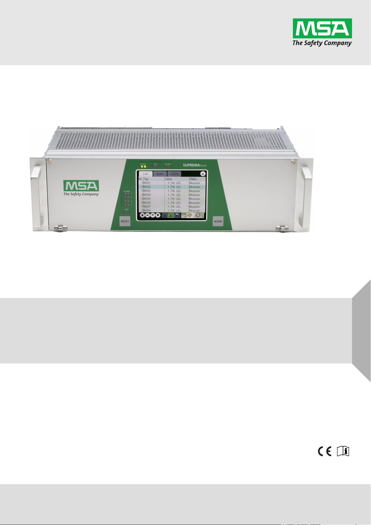
SUPREMATouch
Fire and Gas Warning Unit
Order No.: 10121863/05
MSAsafety.com
Page 2

For the Declaration of Conformity, please visit the product page on MSAsafety.com.
Software Versions
The operation manual refers to the following software versions:
Module
Software version
Flash or EPROM
MCP 20 3.02.01
MDO 20 3.02.01
MGO 20 3.01.02
MAO 20 3.01.02
MAI30/MAR30 1.01.01
MGI30/MGR30 1.01.01
Software status ATEX and TÜV SIL 3
MSA Europe GmbH
Schlüsselstrasse 12
8645 Rapperswil-Jona
Switzerland
info.ch@MSAsafety.com
www.MSAsafety.com
©
MSA 2017 All rights reserved
Page 3

Contents
1 Safety Regulations . . . . . . . . . . . . . . . . . . . . . . . . . . . . . . . . . . . . . . . . . . . . . . . . . . . . . . . . . . . . . . . . . 10
1.1 Correct Use . . . . . . . . . . . . . . . . . . . . . . . . . . . . . . . . . . . . . . . . . . . . . . . . . . . . . . . . . . . . . . . .. . 10
1.2 Liability Information . . . . . . . . . . . . . . . . . . . . . . . . . . . . . . . . . . . . . . . . . . . . . . . . . . . . . . . . . . . . 10
2 System Concept . . . . . . . . . . . . . . . . . . . . . . . . . . . . . . . . . . . . . . . . . . . . . . . . . . . . . . . . . . . . . . . . . . . 11
2.1 System Features . . . . . . . . . . . . . . . . . . . . . . . . . . . . . . . . . . . . . . . . . . . . . . . . . . . . . . . . . . . . . . 11
2.2 Design . . . . . . . . . . . . . . . . . . . . . . . . . . . . . . . . . . . . . . . . . . . . . . . . . . . . . . . . . . . . . . . . . . . . . . 12
2.3 Operation and Display unit MDO . . . . . . . . . . . . . . . . . . . . . . . . . . . . . . . . . . . . . . . . . . . . . . . . . . 14
2.4 Keys . . . . . . . . . . . . . . . . . . . . . . . . . . . . . . . . . . . . . . . . . . . . . . . . . . . . . . . . . . . . . . . . . . . . . . . . 15
2.5 LED Indicators . . . . . . . . . . . . . . . . . . . . . . . . . . . . . . . . . . . . . . . . . . . . . . . . . . . . . . . . . . . . . . . . 15
2.6 Bus Protocol. . . . . . . . . . . . . . . . . . . . . . . . . . . . . . . . . . . . . . . . . . . . . . . . . . . . . . . . . . . . . . . . . . 16
2.7 System Power Supply . . . . . . . . . . . . . . . . . . . . . . . . . . . . . . . . . . . . . . . . . . . . . . . . . . . . . . . . . . 16
2.8 Safety Concept. . . . . . . . . . . . . . . . . . . . . . . . . . . . . . . . . . . . . . . . . . . . . . . . . . . . . . . . . . . . . . . . 17
2.9 During Operation . . . . . . . . . . . . . . . . . . . . . . . . . . . . . . . . . . . . . . . . . . . . . . . . . . . . . . . . . . . . . . 18
3 System Operation . . . . . . . . . . . . . . . . . . . . . . . . . . . . . . . . . . . . . . . . . . . . . . . . . . . . . . . . . . . . . . . .. . 19
3.1 Operation Menu . . . . . . . . . . . . . . . . . . . . . . . . . . . . . . . . . . . . . . . . . . . . . . . . . . . . . . . . . . . . . . . 19
3.2 Access Authorisation . . . . . . . . . . . . . . . . . . . . . . . . . . . . . . . . . . . . . . . . . . . . . . . . . . . . . . . . . . . 19
3.3 Measure Menu . . . . . . . . . . . . . . . . . . . . . . . . . . . . . . . . . . . . . . . . . . . . . . . . . . . . . . . . . . . . . . . . 20
4 Entering System Parameters . . . . . . . . . . . . . . . . . . . . . . . . . . . . . . . . . . . . . . . . . . . . . . . . . . . . . . . . . 27
4.1 Setup Menu . . . . . . . . . . . . . . . . . . . . . . . . . . . . . . . . . . . . . . . . . . . . . . . . . . . . . . . . . . . . . . . .. . 30
Measuring Points Submenu . . . . . . . . . . . . . . . . . . . . . . . . . . . . . . . . . . . . . . . . . . . . . . . . . . . . . . 30
Information Subwindow . . . . . . . . . . . . . . . . . . . . . . . . . . . . . . . . . . . . . . . . . . . . . . . . . . . . . . . . . 32
Sensor Data Subwindow . . . . . . . . . . . . . . . . . . . . . . . . . . . . . . . . . . . . . . . . . . . . . . . . . . . . . . . . 32
Alarms Subwindow. . . . . . . . . . . . . . . . . . . . . . . . . . . . . . . . . . . . . . . . . . . . . . . . . . . . . . . . . . . . . 33
Relay Output Assignment Window. . . . . . . . . . . . . . . . . . . . . . . . . . . . . . . . . . . . . . . . . . . . . . . . . 35
Relay Outputs Window. . . . . . . . . . . . . . . . . . . . . . . . . . . . . . . . . . . . . . . . . . . . . . . . . . . . . . . . . . 38
Password . . . . . . . . . . . . . . . . . . . . . . . . . . . . . . . . . . . . . . . . . . . . . . . . . . . . . . . . . . . . . . . . . . . . 46
Display . . . . . . . . . . . . . . . . . . . . . . . . . . . . . . . . . . . . . . . . . . . . . . . . . . . . . . . . . . . . . . . . . . . . . . 47
Time Window . . . . . . . . . . . . . . . . . . . . . . . . . . . . . . . . . . . . . . . . . . . . . . . . . . . . . . . . . . . . . . . . . 48
TCP/IP window. . . . . . . . . . . . . . . . . . . . . . . . . . . . . . . . . . . . . . . . . . . . . . . . . . . . . . . . . . . . . . . . 49
Sensors Submenu . . . . . . . . . . . . . . . . . . . . . . . . . . . . . . . . . . . . . . . . . . . . . . . . . . . . . . . . . . . . .
Head Parameters . . . . . . . . . . . . . . . . . . . . . . . . . . . . . . . . . . . . . . . . . . . . . . . . . . . . . . . . . . . . . . 50
Status Texts . . . . . . . . . . . . . . . . . . . . . . . . . . . . . . . . . . . . . . . . . . . . . . . . . . . . . . . . . . . . . . . . . . 51
Gas Names . . . . . . . . . . . . . . . . . . . . . . . . . . . . . . . . . . . . . . . . . . . . . . . . . . . . . . . . . . . . . . . .. . 52
Measuring Ranges . . . . . . . . . . . . . . . . . . . . . . . . . . . . . . . . . . . . . . . . . . . . . . . . . . . . . . . . . . . . . 53
Dimensions. . . . . . . . . . . . . . . . . . . . . . . . . . . . . . . . . . . . . . . . . . . . . . . . . . . . . . . . . . . . . . . . . . . 54
Linearity Tables . . . . . . . . . . . . . . . . . . . . . . . . . . . . . . . . . . . . . . . . . . . . . . . . . . . . . . . . . . . . . . . 54
Assignment. . . . . . . . . . . . . . . . . . . . . . . . . . . . . . . . . . . . . . . . . . . . . . . . . . . . . . . . . . . . . . . . . . . 55
Allocation . . . . . . . . . . . . . . . . . . . . . . . . . . . . . . . . . . . . . . . . . . . . . . . . . . . . . . . . . . . . . . . . . . . . 56
SD card Window. . . . . . . . . . . . . . . . . . . . . . . . . . . . . . . . . . . . . . . . . . . . . . . . . . . . . . . . . . . . . . . 56
Printer. . . . . . . . . . . . . . . . . . . . . . . . . . . . . . . . . . . . . . . . . . . . . . . . . . . . . . . . . . . . . . . . . . . . . . . 58
4.2 Maintain Menu . . . . . . . . . . . . . . . . . . . . . . . . . . . . . . . . . . . . . . . . . . . . . . . . . . . . . . . . . . . . . . . . 60
Calibration Submenu . . . . . . . . . . . . . . . . . . . . . . . . . . . . . . . . . . . . . . . . . . . . . . . . . . . . . . . . . . . 60
IBR (Bridge Current) Window. . . . . . . . . . . . . . . . . . . . . . . . . . . . . . . . . . . . . . . . . . . . . . . . . . . . . 60
Interface Tests . . . . . . . . . . . . . . . . . . . . . . . . . . . . . . . . . . . . . . . . . . . . . . . . . . . . . . . . . . . . . . . . 61
SD Backup Window . . . . . . . . . . . . . . . . . . . . . . . . . . . . . . . . . . . . . . . . . . . . . . . . . . . . . . . . . . . . 65
49
GB
SUPREMATouch
3
Page 4

4.3 Diagnosis Menu . . . . . . . . . . . . . . . . . . . . . . . . . . . . . . . . . . . . . . . . . . . . . . . . . . . . . . . . . . . . . . . 66
Measuring Points . . . . . . . . . . . . . . . . . . . . . . . . . . . . . . . . . . . . . . . . . . . . . . . . . . . . . . . . . . . . . . 69
Switch Inputs Window . . . . . . . . . . . . . . . . . . . . . . . . . . . . . . . . . . . . . . . . . . . . . . . . . . . . . . . . . . 70
Modules Menu . . . . . . . . . . . . . . . . . . . . . . . . . . . . . . . . . . . . . . . . . . . . . . . . . . . . . . . . . . . . . . . . 70
4.4 PC Operation . . . . . . . . . . . . . . . . . . . . . . . . . . . . . . . . . . . . . . . . . . . . . . . . . . . . . . . . . . . . . . . . . 71
5 Maintenance. . . . . . . . . . . . . . . . . . . . . . . . . . . . . . . . . . . . . . . . . . . . . . . . . . . . . . . . . . . . . . . . . . . . . . . 74
5.1 Sensor Simulation Modules . . . . . . . . . . . . . . . . . . . . . . . . . . . . . . . . . . . . . . . . . . . . . . . . . . . . . . 74
5.2 Replacing Sensors . . . . . . . . . . . . . . . . . . . . . . . . . . . . . . . . . . . . . . . . . . . . . . . . . . . . . . . . . . . . . 75
5.3 Replacing Sensors . . . . . . . . . . . . . . . . . . . . . . . . . . . . . . . . . . . . . . . . . . . . . . . . . . . . . . . . . . . . . 76
6 Service . . . . . . . . . . . . . . . . . . . . . . . . . . . . . . . . . . . . . . . . . . . . . . . . . . . . . . . . . . . . . . . . . . . . . . . . . . . 78
6.1 Plug-In Modules– Status LED . . . . . . . . . . . . . . . . . . . . . . . . . . . . . . . . . . . . . . . . . . . . . . . . . . . . 78
6.2 Replacing Modules. . . . . . . . . . . . . . . . . . . . . . . . . . . . . . . . . . . . . . . . . . . . . . . . . . . . . . . . . . . . . 79
Plug-In Modules . . . . . . . . . . . . . . . . . . . . . . . . . . . . . . . . . . . . . . . . . . . . . . . . . . . . . . . . . . . . . . . 79
6.3 Diagnostic Functions . . . . . . . . . . . . . . . . . . . . . . . . . . . . . . . . . . . . . . . . . . . . . . . . . . . . . . . . . . . 80
6.4 System Fail Messages . . . . . . . . . . . . . . . . . . . . . . . . . . . . . . . . . . . . . . . . . . . . . . . . . . . . . . . . . . 81
6.5 ID Rack Assignment in decimal and hexadecimal figures . . . . . . . . . . . . . . . . . . . . . . . . . . . . . . . 83
6.6 Digital Message Priority . . . . . . . . . . . . . . . . . . . . . . . . . . . . . . . . . . . . . . . . . . . . . . . . . . . . . . . . . 84
6.7 LED and Sounder Test. . . . . . . . . . . . . . . . . . . . . . . . . . . . . . . . . . . . . . . . . . . . . . . . . . . . . . . . . . 84
6.8 System Configuration. . . . . . . . . . . . . . . . . . . . . . . . . . . . . . . . . . . . . . . . . . . . . . . . . . . . . . . . . . . 85
7 Calibration . . . . . . . . . . . . . . . . . . . . . . . . . . . . . . . . . . . . . . . . . . . . . . . . . . . . . . . . . . . . . . . . . . . . . . . . 86
7.1 Calibration Submenu . . . . . . . . . . . . . . . . . . . . . . . . . . . . . . . . . . . . . . . . . . . . . . . . . . . . . . . . . . . 86
7.2 Calibrating Passive Detectors . . . . . . . . . . . . . . . . . . . . . . . . . . . . . . . . . . . . . . . . . . . . . . . . . . . . 89
7.3 First Calibration with Pre-Adjustment. . . . . . . . . . . . . . . . . . . . . . . . . . . . . . . . . . . . . . . . . . . . . . . 92
Passive Detectors . . . . . . . . . . . . . . . . . . . . . . . . . . . . . . . . . . . . . . . . . . . . . . . . . . . . . . . . . . . . . 92
7.4 Calibrating Active Transmitters . . . . . . . . . . . . . . . . . . . . . . . . . . . . . . . . . . . . . . . . . . . . . . . . . . . 92
Calibration with a Variable Power Source . . . . . . . . . . . . . . . . . . . . . . . . . . . . . . . . . . . . . . . . . . . 93
Calibration Using the Transmitter. . . . . . . . . . . . . . . . . . . . . . . . . . . . . . . . . . . . . . . . . . . . . . . . . . 94
7.5 Calibration with Automatic Valve Control . . . . . . . . . . . . . . . . . . . . . . . . . . . . . . . . . . . . . . . . . . . . 94
7.6 Separate Zero Adjustment . . . . . . . . . . . . . . . . . . . . . . . . . . . . . . . . . . . . . . . . . . . . . . . . . . . . . . . 94
7.7 Calibration of Groups of Measuring Points. . . . . . . . . . . . . . . . . . . . . . . . . . . . . . . . . . . . . . . . . . . 95
7.8 Remote Calibration of Transmitters . . . . . . . . . . . . . . . . . . . . . . . . . . . . . . . . . . . . . . . . . . . . . . . . 95
7.9 Setting the Bridge Current
8 System Expansions. . . . . . . . . . . . . . . . . . . . . . . . . . . . . . . . . . . . . . . . . . . . . . . . . . . . . . . . . . . . . . . . . 97
8.1 Connecting Additional Sensors . . . . . . . . . . . . . . . . . . . . . . . . . . . . . . . . . . . . . . . . . . . . . . . . . . . 97
8.2 Connection of Additional Relay Driver Outputs . . . . . . . . . . . . . . . . . . . . . . . . . . . . . . . . . . . . . . . 98
8.3 Connection of Additional Analog Outputs. . . . . . . . . . . . . . . . . . . . . . . . . . . . . . . . . . . . . . . . . . . . 99
. . . . . . . . . . . . . . . . . . . . . . . . . . . . . . . . . . . . . . . . . . . . . . . . . . . . . . . 95
GB
9 Special conditions to comply with the requirements of DIN EN 61508 for SIL 1-3 according to
TÜV Certificate. . . . . . . . . . . . . . . . . . . . . . . . . . . . . . . . . . . . . . . . . . . . . . . . . . . . . . . . . . . . . . . . . . . . 102
9.1 Conditions for configuration, installation, operation and maintenance . . . . . . . . . . . . . . . . . . . . . 102
9.2 Additional conditions to fulfill the requirements of IEC 61508 for a certain SIL . . . . . . . . . . . . . . 103
9.3 Possible Configurations and Acquirable SILs . . . . . . . . . . . . . . . . . . . . . . . . . . . . . . . . . . . . . . . 103
9.4 Configurations . . . . . . . . . . . . . . . . . . . . . . . . . . . . . . . . . . . . . . . . . . . . . . . . . . . . . . . . . . . . . . . 104
9.5 Permitted System Expansions over CAN Bus . . . . . . . . . . . . . . . . . . . . . . . . . . . . . . . . . . . . . . . 107
9.6 Permitted Hardware Modules and Software Versions . . . . . . . . . . . . . . . . . . . . . . . . . . . . . . . . . 108
9.7 Permitted Software Versions . . . . . . . . . . . . . . . . . . . . . . . . . . . . . . . . . . . . . . . . . . . . . . . . . . . . 109
9.8 TÜV-Certificate. . . . . . . . . . . . . . . . . . . . . . . . . . . . . . . . . . . . . . . . . . . . . . . . . . . . . . . . . . . . . . . 109
SUPREMATouch
4
Page 5

10 Special conditions to comply with the requirements of ATEX . . . . . . . . . . . . . . . . . . . . . . . . . . . . . 110
10.1 Standards . . . . . . . . . . . . . . . . . . . . . . . . . . . . . . . . . . . . . . . . . . . . . . . . . . . . . . . . . . . . . . . . . . . 113
11 Modules . . . . . . . . . . . . . . . . . . . . . . . . . . . . . . . . . . . . . . . . . . . . . . . . . . . . . . . . . . . . . . . . . . . . . . . . . 114
11.1 Measurement Value Input . . . . . . . . . . . . . . . . . . . . . . . . . . . . . . . . . . . . . . . . . . . . . . . . . . . . . . 114
11.2 Data Processing/MCP Module (Central Processing Module). . . . . . . . . . . . . . . . . . . . . . . . . . . . 114
11.3 Display + Operation/MDO Module (Display and Operating Module) . . . . . . . . . . . . . . . . . . . . . . 115
11.4 Digital + Analog Output . . . . . . . . . . . . . . . . . . . . . . . . . . . . . . . . . . . . . . . . . . . . . . . . . . . . . . . . 116
11.5 Power Supply, Bus Connections, Connecting Technique . . . . . . . . . . . . . . . . . . . . . . . . . . . . . . 117
MSP Module (System Power Module) . . . . . . . . . . . . . . . . . . . . . . . . . . . . . . . . . . . . . . . . . . . . . 117
MIB Module (Interconnection Board) . . . . . . . . . . . . . . . . . . . . . . . . . . . . . . . . . . . . . . . . . . . . . . 117
MST Module (System Terminals). . . . . . . . . . . . . . . . . . . . . . . . . . . . . . . . . . . . . . . . . . . . . . . . . 118
MAT Module (analogue Terminal Module) . . . . . . . . . . . . . . . . . . . . . . . . . . . . . . . . . . . . . . . . . . 118
MAT Module TS (analogue Terminal Module) . . . . . . . . . . . . . . . . . . . . . . . . . . . . . . . . . . . . . . . 118
MUT Module (Universal Terminals) . . . . . . . . . . . . . . . . . . . . . . . . . . . . . . . . . . . . . . . . . . . . . . . 118
MRO8 Module (Relay Output Module: Common Alarms) . . . . . . . . . . . . . . . . . . . . . . . . . . . . . . 119
MRC TS Module (Relay Connection Module) . . . . . . . . . . . . . . . . . . . . . . . . . . . . . . . . . . . . . . . 119
MRO8 TS Module (Relay Output Module: Non-redundant) . . . . . . . . . . . . . . . . . . . . . . . . . . . . . 119
MRO8 TS Module: Function of the Module . . . . . . . . . . . . . . . . . . . . . . . . . . . . . . . . . . . . . . . . . 119
MRO8 TS Module: Relay Assignment . . . . . . . . . . . . . . . . . . . . . . . . . . . . . . . . . . . . . . . . . . . . . 120
MRO16 TS Module (Relay Output Module (Redundant)) . . . . . . . . . . . . . . . . . . . . . . . . . . . . . . 120
MRO16 TS Module: Module Function . . . . . . . . . . . . . . . . . . . . . . . . . . . . . . . . . . . . . . . . . . . . . 120
MRO16 TS Module: Relay Assignment . . . . . . . . . . . . . . . . . . . . . . . . . . . . . . . . . . . . . . . . . . . . 120
11.6 Minimal Module Requirements. . . . . . . . . . . . . . . . . . . . . . . . . . . . . . . . . . . . . . . . . . . . . . . . . . . 120
12 Installation . . . . . . . . . . . . . . . . . . . . . . . . . . . . . . . . . . . . . . . . . . . . . . . . . . . . . . . . . . . . . . . . . . . . . . . 121
12.1 Installation Site. . . . . . . . . . . . . . . . . . . . . . . . . . . . . . . . . . . . . . . . . . . . . . . . . . . . . . . . . . . . . . . 121
12.2 Installation Instructions for Following the EMC Directives . . . . . . . . . . . . . . . . . . . . . . . . . . . . . . 121
Instruction on Meeting the EMC Requirements on the SUPREMATouch Control System . . . . . 122
12.3 Installation, Step by Step . . . . . . . . . . . . . . . . . . . . . . . . . . . . . . . . . . . . . . . . . . . . . . . . . . . . . . . 123
12.4 Unpacking . . . . . . . . . . . . . . . . . . . . . . . . . . . . . . . . . . . . . . . . . . . . . . . . . . . . . . . . . . . . . . . . . . 124
12.5 Cabling . . . . . . . . . . . . . . . . . . . . . . . . . . . . . . . . . . . . . . . . . . . . . . . . . . . . . . . . . . . . . . . . . . . . . 124
12.6 Module Configuration . . . . . . . . . . . . . . . . . . . . . . . . . . . . . . . . . . . . . . . . . . . . . . . . . . . . . . . . . . 126
Configuration MIB Module
Configuration MAT Module. . . . . . . . . . . . . . . . . . . . . . . . . . . . . . . . . . . . . . . . . . . . . . . . . . . . . . 129
Configuration MAT TS Module. . . . . . . . . . . . . . . . . . . . . . . . . . . . . . . . . . . . . . . . . . . . . . . . . . . 130
Configuration MRO8 Module . . . . . . . . . . . . . . . . . . . . . . . . . . . . . . . . . . . . . . . . . . . . . . . . . . . . 131
Configuration MRC TS Module . . . . . . . . . . . . . . . . . . . . . . . . . . . . . . . . . . . . . . . . . . . . . . . . . . 132
Configuration MRO8 TS Module . . . . . . . . . . . . . . . . . . . . . . . . . . . . . . . . . . . . . . . . . . . . . . . . . 132
Configuration MRO16 TS Module . . . . . . . . . . . . . . . . . . . . . . . . . . . . . . . . . . . . . . . . . . . . . . . . 132
Configuration MUT Module . . . . . . . . . . . . . . . . . . . . . . . . . . . . . . . . . . . . . . . . . . . . . . . . . . . . . 132
Configuration MAR Module . . . . . . . . . . . . . . . . . . . . . . . . . . . . . . . . . . . . . . . . . . . . . . . . . . . . . 132
Configuration MST Module. . . . . . . . . . . . . . . . . . . . . . . . . . . . . . . . . . . . . . . . . . . . . . . . . . . . . . 132
Configuration MAO Module (MAO20) . . . . . . . . . . . . . . . . . . . . . . . . . . . . . . . . . . . . . . . . . . . . . 132
Configuration MCP20 Module . . . . . . . . . . . . . . . . . . . . . . . . . . . . . . . . . . . . . . . . . . . . . . . . . . . 135
Configuration MDO20 Module . . . . . . . . . . . . . . . . . . . . . . . . . . . . . . . . . . . . . . . . . . . . . . . . . . . 136
Configuration MDC20 Module . . . . . . . . . . . . . . . . . . . . . . . . . . . . . . . . . . . . . . . . . . . . . . . . . . . 137
Configuration MAI30/MGI30. . . . . . . . . . . . . . . . . . . . . . . . . . . . . . . . . . . . . . . . . . . . . . . . . . . . . 137
Configuration MAR30/MGR30 . . . . . . . . . . . . . . . . . . . . . . . . . . . . . . . . . . . . . . . . . . . . . . . . . . . 138
Configuration MHS30. . . . . . . . . . . . . . . . . . . . . . . . . . . . . . . . . . . . . . . . . . . . . . . . . . . . . . . . . . 138
Configuration MBC20 Module . . . . . . . . . . . . . . . . . . . . . . . . . . . . . . . . . . . . . . . . . . . . . . . . . . . 138
Configuration MBT20 Module. . . . . . . . . . . . . . . . . . . . . . . . . . . . . . . . . . . . . . . . . . . . . . . . . . . . 139
. . . . . . . . . . . . . . . . . . . . . . . . . . . . . . . . . . . . . . . . . . . . . . . . . . . . . . 126
GB
SUPREMATouch
5
Page 6

Configuration in the SUPREMATouch menu . . . . . . . . . . . . . . . . . . . . . . . . . . . . . . . . . . . . . . . . 139
MRD Dummy Relay . . . . . . . . . . . . . . . . . . . . . . . . . . . . . . . . . . . . . . . . . . . . . . . . . . . . . . . . . . . 139
12.7 System Configuration (Hardware) . . . . . . . . . . . . . . . . . . . . . . . . . . . . . . . . . . . . . . . . . . . . . . . . 141
Front: . . . . . . . . . . . . . . . . . . . . . . . . . . . . . . . . . . . . . . . . . . . . . . . . . . . . . . . . . . . . . . . . . . . . . . 141
Rear:. . . . . . . . . . . . . . . . . . . . . . . . . . . . . . . . . . . . . . . . . . . . . . . . . . . . . . . . . . . . . . . . . . . . . . . 141
System Requirements . . . . . . . . . . . . . . . . . . . . . . . . . . . . . . . . . . . . . . . . . . . . . . . . . . . . . . . . . 142
Maximum Loads. . . . . . . . . . . . . . . . . . . . . . . . . . . . . . . . . . . . . . . . . . . . . . . . . . . . . . . . . . . . . . 143
Configuration Examples . . . . . . . . . . . . . . . . . . . . . . . . . . . . . . . . . . . . . . . . . . . . . . . . . . . . . . . . 144
12.8 Systems Consisting of Several Racks . . . . . . . . . . . . . . . . . . . . . . . . . . . . . . . . . . . . . . . . . . . . . 145
Systems with Central Recording of Measuring Values . . . . . . . . . . . . . . . . . . . . . . . . . . . . . . . . 145
12.9 Connecting the Sensors . . . . . . . . . . . . . . . . . . . . . . . . . . . . . . . . . . . . . . . . . . . . . . . . . . . . . . . . 152
12.10 Connecting the Relay Outputs . . . . . . . . . . . . . . . . . . . . . . . . . . . . . . . . . . . . . . . . . . . . . . . . . . . 157
12.11 Connecting the Switching Outputs. . . . . . . . . . . . . . . . . . . . . . . . . . . . . . . . . . . . . . . . . . . . . . . . 166
12.12 Connecting the Analog Outputs . . . . . . . . . . . . . . . . . . . . . . . . . . . . . . . . . . . . . . . . . . . . . . . . . . 169
12.13 System Ports (MST Module) . . . . . . . . . . . . . . . . . . . . . . . . . . . . . . . . . . . . . . . . . . . . . . . . . . . . 171
12.14 Connecting the System Power Supply . . . . . . . . . . . . . . . . . . . . . . . . . . . . . . . . . . . . . . . . . . . . . 174
12.15 Labelling Concept. . . . . . . . . . . . . . . . . . . . . . . . . . . . . . . . . . . . . . . . . . . . . . . . . . . . . . . . . . . . . 178
13 Start-Up . . . . . . . . . . . . . . . . . . . . . . . . . . . . . . . . . . . . . . . . . . . . . . . . . . . . . . . . . . . . . . . . . . . . . . . . . 181
13.1 Start-up Procedure Overview . . . . . . . . . . . . . . . . . . . . . . . . . . . . . . . . . . . . . . . . . . . . . . . . . . . . 181
13.2 Switch On the Supply Voltage . . . . . . . . . . . . . . . . . . . . . . . . . . . . . . . . . . . . . . . . . . . . . . . . . . . 181
13.3 System Configuration/Parameterisation. . . . . . . . . . . . . . . . . . . . . . . . . . . . . . . . . . . . . . . . . . . . 181
13.4 Preadjusting Passive Detectors . . . . . . . . . . . . . . . . . . . . . . . . . . . . . . . . . . . . . . . . . . . . . . . . . . 182
13.5 First Calibration with Pre-Adjustment . . . . . . . . . . . . . . . . . . . . . . . . . . . . . . . . . . . . . . . . . . . . . . 182
13.6 Completing Startup. . . . . . . . . . . . . . . . . . . . . . . . . . . . . . . . . . . . . . . . . . . . . . . . . . . . . . . . . . . . 182
14 Connecting Peripheral Equipment. . . . . . . . . . . . . . . . . . . . . . . . . . . . . . . . . . . . . . . . . . . . . . . . . . . . 183
14.1 Connecting a PC/Laptop . . . . . . . . . . . . . . . . . . . . . . . . . . . . . . . . . . . . . . . . . . . . . . . . . . . . . . . 183
14.2 Connecting a Protocol Printer . . . . . . . . . . . . . . . . . . . . . . . . . . . . . . . . . . . . . . . . . . . . . . . . . . . 185
14.3 Bus Connection . . . . . . . . . . . . . . . . . . . . . . . . . . . . . . . . . . . . . . . . . . . . . . . . . . . . . . . . . . . . . . 186
15 Redundant Systems . . . . . . . . . . . . . . . . . . . . . . . . . . . . . . . . . . . . . . . . . . . . . . . . . . . . . . . . . . . . . . . 188
15.1 Application/Function Safety . . . . . . . . . . . . . . . . . . . . . . . . . . . . . . . . . . . . . . . . . . . . . . . . . . . . . 188
15.2 Function of Redundant Systems . . . . . . . . . . . . . . . . . . . . . . . . . . . . . . . . . . . . . . . . . . . . . . . . . 188
15.3 Design of the Redundant System. . . . . . . . . . . . . . . . . . . . . . . . . . . . . . . . . . . . . . . . . . . . . . . . . 190
15.4 Start-Up . . . . . . . . . . . . . . . . . . . . . . . . . . . . . . . . . . . . . . . . . . . . . . . . . . . . . . . . . . . . . . . . . . . . 194
16 Sensor Data . . . . . . . . . . . . . . . . . . . . . . . . . . . . . . . . . . . . . . . . . . . . . . . . . . . . . . . . . . . . . . . . . . . . . . 196
16.1 4-20 mA (2-wire). . . . . . . . . . . . . . . . . . . . . . . . . . . . . . . . . . . . . . . . . . . . . . . . . . . . . . . . . . . . . . 197
16.2 4-20 mA (3-wire). . . . . . . . . . . . . . . . . . . . . . . . . . . . . . . . . . . . . . . . . . . . . . . . . . . . . . . . . . . . . . 198
16.3 4-20 mA with ext. power supply . . . . . . . . . . . . . . . . . . . . . . . . . . . . . . . . . . . . . . . . . . . . . . . . . . 199
16.4 Series 47K-ST, -PRP (3-wire) . . . . . . . . . . . . . . . . . . . . . . . . . . . . . . . . . . . . . . . . . . . . . . . . . . . 203
16.5 Series 47K-ST, -PRP (5-wire) . . . . . . . . . . . . . . . . . . . . . . . . . . . . . . . . . . . . . . . . . . . . . . . . . . . 202
16.6 Series 47K-HT (3-wire). . . . . . . . . . . . . . . . . . . . . . . . . . . . . . . . . . . . . . . . . . . . . . . . . . . . . . . . . 208
16.7 Series 47K-HT (5-wire). . . . . . . . . . . . . . . . . . . . . . . . . . . . . . . . . . . . . . . . . . . . . . . . . . . . . . . . . 210
16.8 Fire Detector Apollo Series 65 (not explosion-proof) (without safety barrier). . . . . . . . . . . . . . . . 209
16.9 Push-Button Detector (not explosion-proof) (without safety barrier) . . . . . . . . . . . . . . . . . . . . . . 211
16.10 Explosion-proof Push-Button Detector with Barrier Z 787 . . . . . . . . . . . . . . . . . . . . . . . . . . . . . . 212
16.11 Ex-Fire Detector Apollo Series 60 with Barrier Z 787 and MTL 710pressure-resistant . . . . . . . . 214
16.12 Explosions-Proof Fire Detector CERBERUS DO1101EX/DT1101EX with Barrier Z 787 . . . . . . 216
16.13 Explosion-Proof Push-Button Detector with Barriers MTL 728 and MTL 710 . . . . . . . . . . . . . . . 218
16.14 Explosion-Proof Fire Detector Apollo Series 60 with Barriers MTL 728. . . . . . . . . . . . . . . . . . . . 220
16.15 Explosion-Proof Fire Detector CERBERUS DO1101EX/DT1101EX with Barriers MTL 728 and
MTL 710 . . . . . . . . . . . . . . . . . . . . . . . . . . . . . . . . . . . . . . . . . . . . . . . . . . . . . . . . . . . . . . . . . . . . 222
GB
SUPREMATouch
6
Page 7

17 Technical Data . . . . . . . . . . . . . . . . . . . . . . . . . . . . . . . . . . . . . . . . . . . . . . . . . . . . . . . . . . . . . . . . . . . . 224
17.1 MAI30/MGI30 Module: Analog Input Unit. . . . . . . . . . . . . . . . . . . . . . . . . . . . . . . . . . . . . . . . . . . 225
17.2 MAR30/MGR30 Module: analogue Redundant . . . . . . . . . . . . . . . . . . . . . . . . . . . . . . . . . . . . . . 225
17.3 MAT Module: Analogue Terminal Unit . . . . . . . . . . . . . . . . . . . . . . . . . . . . . . . . . . . . . . . . . . . . . 225
17.4 MAO20 Module: Analog Output Unit . . . . . . . . . . . . . . . . . . . . . . . . . . . . . . . . . . . . . . . . . . . . . . 225
17.5 MBC Module: Bus Communication . . . . . . . . . . . . . . . . . . . . . . . . . . . . . . . . . . . . . . . . . . . . . . . 226
17.6 MCP Module: Central Processing Unit. . . . . . . . . . . . . . . . . . . . . . . . . . . . . . . . . . . . . . . . . . . . . 226
17.7 MDC Module: Display Connection . . . . . . . . . . . . . . . . . . . . . . . . . . . . . . . . . . . . . . . . . . . . . . . . 226
17.8 MDO Module: Display + Operating Unit . . . . . . . . . . . . . . . . . . . . . . . . . . . . . . . . . . . . . . . . . . . . 226
17.9 MGO Module: General Output Unit . . . . . . . . . . . . . . . . . . . . . . . . . . . . . . . . . . . . . . . . . . . . . . . 226
17.10 MHD TS Module: Modular High Driver . . . . . . . . . . . . . . . . . . . . . . . . . . . . . . . . . . . . . . . . . . . . . 227
17.11 MHS30 Module: Module HART Support . . . . . . . . . . . . . . . . . . . . . . . . . . . . . . . . . . . . . . . . . . . 227
17.12 MIB Module: Interconnection Board . . . . . . . . . . . . . . . . . . . . . . . . . . . . . . . . . . . . . . . . . . . . . . . 227
17.13 MRC TS Module: Relay Connection . . . . . . . . . . . . . . . . . . . . . . . . . . . . . . . . . . . . . . . . . . . . . . 228
17.14 MRD Module: Dummy Relay . . . . . . . . . . . . . . . . . . . . . . . . . . . . . . . . . . . . . . . . . . . . . . . . . . . . 228
17.15 MRO10 8 Module: Relay Output Unit. . . . . . . . . . . . . . . . . . . . . . . . . . . . . . . . . . . . . . . . . . . . . . 228
17.16 MRO10 8 TS Module: Relay Output Unit (Rail-Mount Installation) . . . . . . . . . . . . . . . . . . . . . . . 228
17.17 MRO10 16 TS Module: Redundant Relay Output Unit (Rail-Mount Installation) . . . . . . . . . . . . . 229
17.18 MRO20 8 TS . . . . . . . . . . . . . . . . . . . . . . . . . . . . . . . . . . . . . . . . . . . . . . . . . . . . . . . . . . . . . . . . 229
17.19 MRO20 8 TS SSR . . . . . . . . . . . . . . . . . . . . . . . . . . . . . . . . . . . . . . . . . . . . . . . . . . . . . . . . . . . . 229
17.20 MRO20 16 TS . . . . . . . . . . . . . . . . . . . . . . . . . . . . . . . . . . . . . . . . . . . . . . . . . . . . . . . . . . . . . . . 229
17.21 MRO10 16 TS SSR . . . . . . . . . . . . . . . . . . . . . . . . . . . . . . . . . . . . . . . . . . . . . . . . . . . . . . . . . . . 230
17.22 MSP Module: System Power Unit . . . . . . . . . . . . . . . . . . . . . . . . . . . . . . . . . . . . . . . . . . . . . . . . 230
17.23 MST20 Module: System Terminals . . . . . . . . . . . . . . . . . . . . . . . . . . . . . . . . . . . . . . . . . . . . . . . 231
17.24 Relay Contact Data (MRO10) . . . . . . . . . . . . . . . . . . . . . . . . . . . . . . . . . . . . . . . . . . . . . . . . . . . 231
18 Dimensions . . . . . . . . . . . . . . . . . . . . . . . . . . . . . . . . . . . . . . . . . . . . . . . . . . . . . . . . . . . . . . . . . . . . . . 232
18.1 Rack . . . . . . . . . . . . . . . . . . . . . . . . . . . . . . . . . . . . . . . . . . . . . . . . . . . . . . . . . . . . . . . . . . . . . . . 232
18.2 Rail-mounted Modules . . . . . . . . . . . . . . . . . . . . . . . . . . . . . . . . . . . . . . . . . . . . . . . . . . . . . . . . . 233
19 Ordering Information. . . . . . . . . . . . . . . . . . . . . . . . . . . . . . . . . . . . . . . . . . . . . . . . . . . . . . . . . . . . . . . 239
19.1 Modules and Accessories . . . . . . . . . . . . . . . . . . . . . . . . . . . . . . . . . . . . . . . . . . . . . . . . . . . . . . 239
19.2 Sensors . . . . . . . . . . . . . . . . . . . . . . . . . . . . . . . . . . . . . . . . . . . . . . . . . . . . . . . . . . . . . . . . . . . . 240
GB
SUPREMATouch
7
Page 8
User Instruction Manual
SUPREMATouch
Fire and Gas Warning Unit
MSAsafety.com
Page 9

MSA Europe GmbH
Schlüsselstrasse 12
8645 Rapperswil-Jona
Switzerland
info.ch@MSAsafety.com
www.MSAsafety.com
©
MSA 2017 All rights reserved
Page 10

Safety Regulations
1 Safety Regulations
1.1 Correct Use
The SUPREMATouch is a stationary gas warning system with multiple measurement sites, which
operates continuously to monitor work sites for the presence of combustible and toxic mixtures of
gas and/or vapor with air and to monitor the ambient air for oxygen content. The system supplies
power to the sensors, displays the measured concentrations, and monitors the limit values, but it
also actuates alarm devices. The various functions of the gas warning system (the acquisition of
the measurement values, the evaluation of the signals, the actuation of the alarm devices etc.) are
performed by the various modules of the SUPREMATouch.
The SUPREMATouch can process the standardized current and voltage outputs of various types
of sensors. This means that the system can display and evaluate not only gas measurements but
other measurement variables as well (e.g., temperature and pressure).
The SUPREMATouch is a modular system, allowing a wide variety of applications.
It is imperative that this operating manual be read and observed when using the product. In particular, the safety instructions, as well as the information for the use and operation of the product,
must be carefully read and observed. Furthermore, the national regulations applicable in the
user's country must be taken into account for safe use.
DANGER!
This product is supporting life and health. Inappropriate use, maintenance or servicing may affect
the function of the device and thereby seriously compromise the user's life.
Before use the product operability must be verified. The product must not be used if the function
test is unsuccessful, it is damaged, a competent servicing/maintenance has not been made,
genuine MSA spare parts have not been used.
Alternative use, or use outside this specification will be considered as non-compliance. This also
applies especially to unauthorised alterations to the product and to commissioning work that has
not been carried out by MSA or authorised persons.
1.2 Liability Information
MSA accepts no liability in cases where the device has been used inappropriately or not as
intended. The selection and use of the device are the exclusive responsibility of the individual
operator.
Product liability claims, warranties and guarantees made by MSA with respect to the device are
voided, if it is not used, serviced or maintained in accordance with the instructions in this manual.
GB
SUPREMATouch
10
Page 11

System Concept
2 System Concept
2.1 System Features
• Modular system
• 19” rack system for the connection of up to 256 sensors
• Complete system for up to 64 sensors with common relays (Alarms 1–4, signal fail, horn,
inhibit, power) in one 19” rack
• Maximum number of switching outputs in the system: 512
• Minimal installation work (bus system)
• Redundancy possible
• Maximum refresh rate of 3–4 seconds for alarm outputs (1–2 s for data acquisition; 1 s for
computation; 1 s for data output)
• Maximum refresh rate of 3–5 seconds for signal fail outputs (1–2 s for data acquisition; 1–2 s
for computation; 1 s for data output)
• Maximum response time of 15 seconds for system fails
• External voltage operation (85–265 VAC) no switching necessary
• Power supply unit on the rack, 250 W
• For higher power requirements, external power supplies can be connected
• Battery connection for emergency power operation
• Operating voltage range of the system modules: 19.2 VDC–32 VDC.
Recommended voltage: 24 VDC.
• Universal sensor interface with automatic sensor detection
• Operation of passive catalytic/semiconductor sensors, 3- or 5-wire.
• Automatic pre-setting of passive detectors in first calibration
• Operation of active transmitters with 4–20 mA output, 2- or 3-wire
• System operation via a graphical touch screen with a resolution of 320 x 240 pixels and individual function keys
• Self-explanatory error messages
• System configuration and parametrization optionally via laptop (Windows user interface)
• The SUPREMATouch can be connected via a bus connection to the company communications
network (data evaluation, data display, etc.)
• Key switch connection or three password levels to control access
• Key switch connection for relay inhibiting
• Remote key switches for acknowledgment and reset
• Common alarm LEDs for 1st to 4th alarm, signal fail (sensor), system fail, inhibit, power supply
fail
• Protocol printout of status changes + system operations (standard ASCII, 80 CHR)
• 1 x USB + 1 x RS232 or 2 x RS232 interfaces for data transfer to an industrial PC/laptop/printer
• RS232 interfaces are electrically isolated
• RS232/RS485 converters used for longer transmission distances
• 8 MRO Module common alarm relays supplied by the rack power supply unit
• External relays are supplied with power separately
• Recommended operational lifetime according to EN 50271: 20 years
GB
SUPREMATouch
11
Page 12

System Concept
2.2 Design
The modules of the SUPREMATouch are mounted in a rack. For expanded systems, additional
modules can be placed in a second rack or installed on top hat rails in a switch box.
Data is exchanged between the modules over a CAN bus, so it is possible to connect satellites
over long distances.
For measurement tasks that require redundant signal input and processing, additional modules
can be added at any time to expand the gas warning system.
The sensors must have the type of protection against ignition prescribed for the installation site.
The connection between the input module of the SUPREMATouch and the sensors is established
by a screened remote-measurement cable of the 2, 3, 4 or 5 wire type.
For servicing, the sensors can be electrically isolated from the SUPREMATouch by mechanically
disconnecting the plug-in connection (MAT, MAT TS modules).
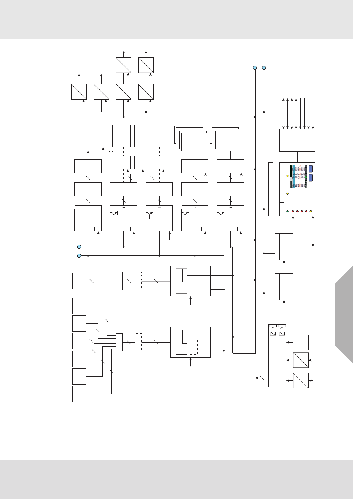
The following block circuit diagram shows the possible layout of a non-redundant system.
Sensors
The system distinguishes between passive detectors and active transmitters.
As a general rule, passive detectors simply consist of a highly sensitive (half) measuring bridge
while active transmitters possess their own electronics and have a standardised signal output
(4–20 mA).
SUPREMATouch
GB
12
Page 13
MRO10 16 TS
MRO20 16 TS
MRO10 16 TS SSR
5 x
5 x
5 x
5 x
5 x
MIB 20
Output
4-20mA
Ext
Int = GWS250-24
Bat
40
5
2
system
failure
relay
Modbus RTU,
Modbus TCP,
Profibus DP
2
CAN BCAN A
Terminator
CANBCANA
Terminator
CANB
CANA
CAN A CAN B
MCP 20
24 V
CAN A CAN B
MCP 20
24 V
24 V
MGI30
MGR30
MAT 10 (TS)
passive
detector
passive
detector
fire/smoke
detector
manual call
point
MUT10
40
3
24V=
ป
24V=
ป
BAT
24V=
MGO 20
24 V, 500 mA
40 Drivers
1
40
CAN
24 V
MGO 20
24 V, 500 mA
40 Drivers
1
40
CAN
MGO 20
24 V, 500 mA
40 Drivers
1
40
CAN
MGO 20
24 V, 500 mA
40 Drivers
1
40
CAN
24 V
24 V
24 V
MUT10
40
MUT10
40
MUT10
40
MRC10
-TS
40
5 x
MRO10 8 TS
MRO20 8 TS
MRO20 8 TS SSR
MRC10
-TS
MRC10
-TS
MRC10
-TS
40
40
MRO10 8 TS
MRO20 8 TS
MRO20 8 TS SSR
5 x
MRO10 8 TS
MRO20 8 TS
MRO20 8 TS SSR
5 x
MHD 10
MAO 20
1
8
CAN
24 V
MUT10
40
MGT40
-TS
40
CAN
24 V
Gateway
CAN
24 V
Modbus RTU,
Modbus TCP,
Profibus DP
CAN bridge
24 V
24 V
CAN
CAN
CAN
CAN
CAN bridge
CAN/fibre optic
24 V
CAN
CAN/fibre optic
24 V
CAN
24 V
24 V
24 V
24 V
24 V
5 x
5 x
5 x
5 x
MUT10
40
MRC10
-TS
40
5 x
MRO10 8 TS
MRO20 8 TS
MRO20 8 TS SSR
24 V
ACK
MDO 20
2. ALARM
1. ALARM
SIGNAL FAILURE
3. ALARM
4. ALARM
CAN A
CAN B
RES
POWER
INHIBIT
SYSTEM
24 V
MDC 20
RS 232 / USB
Lock A/B
Reset
Acknowledge
Password switch
MST 20
2 x CANA, 2 x CANB
RS 232 / USB to PC
Ethernet
RS 232 to Printer
CAN
CAN
40
3
2
3
2
24 V
MAI30
MAR30
MAT 10 (TS)
transmitter
(4..20mA)
transmitter
(4..20mA)
MUT10
40
MHS30
CAN
CAN
Switch
8 x
Gateway
System Concept
GB
Fig. 1 Block circuit diagram of a system layout (redundant)
SUPREMATouch
85VAC...264VAC
24V power supply
13
Page 14
System Concept
Fail Conditions
Signals that are above full-scale range or signal fails that were caused by an interruption of the
digital communication are always latched.
Signal fails caused by signals below the measuring range are non-latching. Measurement values
that are over the full-scale range will trigger all 4 alarms.
Horn
If an audible alarm device is connected to the horn relay, it will sound as soon as a new alarm is
triggered. It continues to sound even when the alarm condition no longer exists. Pressing the
ACKNL key silences the horn, regardless of whether or not the alarm condition still exists.
When a redundant system is used, the ACKNL or RESET key has to be pressed for at
least 1 second.
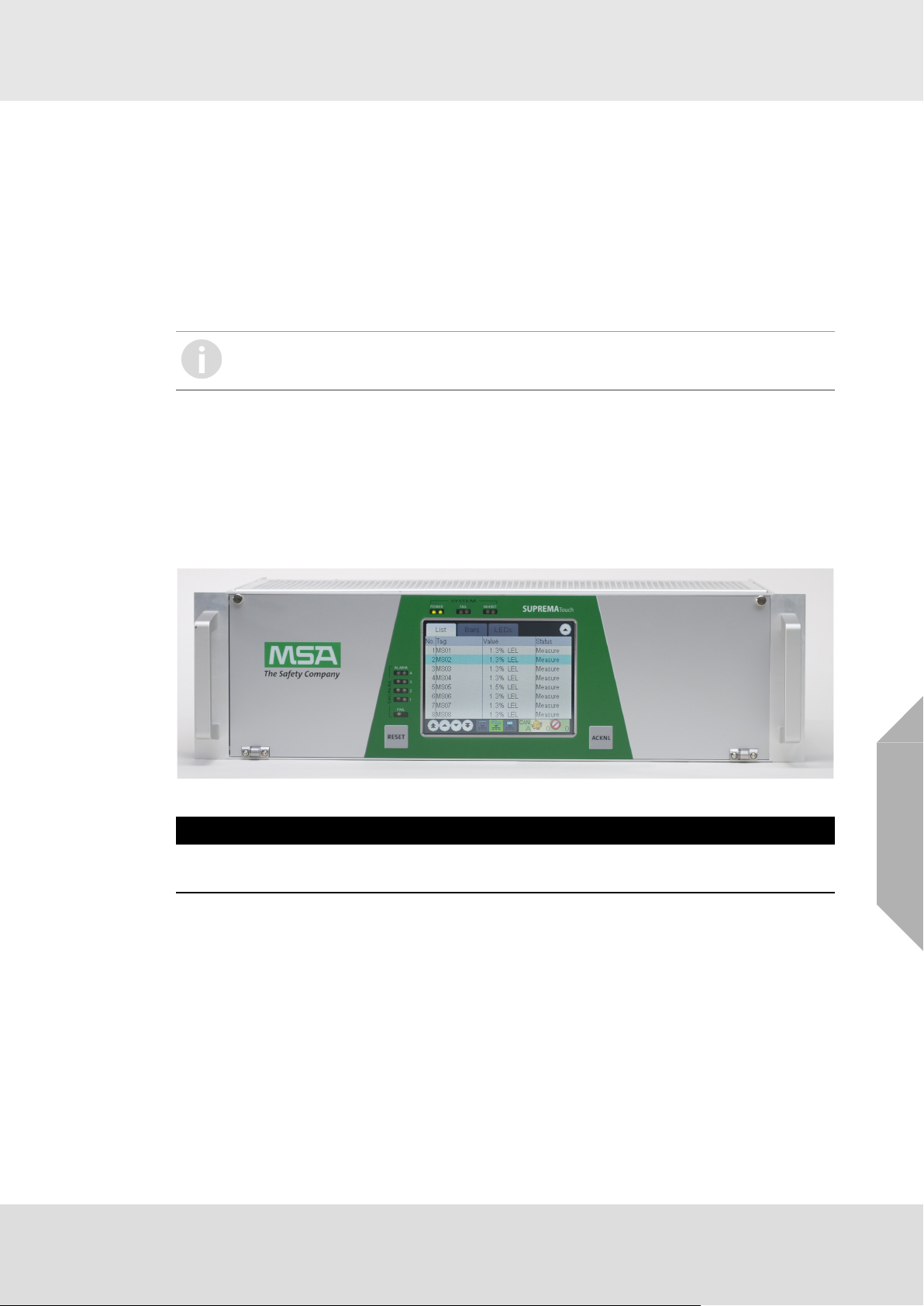
2.3 Operation and Display unit MDO
The operation and display unit includes the following components:
• Colour TFT touch screen with 320 x 240 resolution
• 2 keys
• 8 LED indicators
• 1 beeper
The TFT screen is a full graphic display with a resistive touch panel. The character height is
approximately 4 mm.
Fig. 2 Display and Operation Module (MDO)
NOTICE
To prevent damage to the touch screen, avoid touching it with sharp objects. Only use fingers or
the touch screen pen provided.
GB
SUPREMATouch
14
Page 15
System Concept
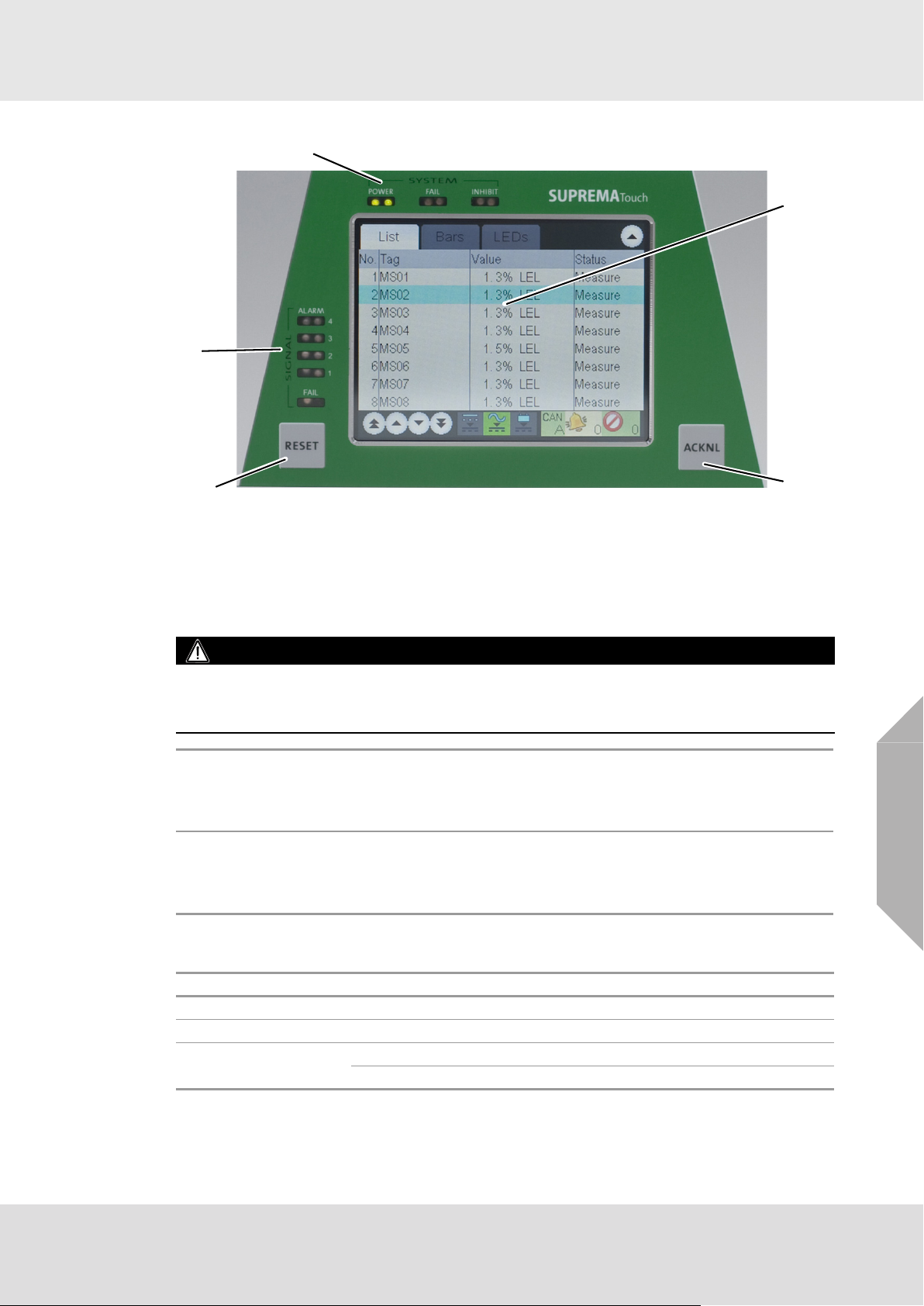
4
3
2
1
6
Fig. 3 Display with keys
1 ACKNL (acknowledge) key 4 SYSTEM LEDs
2 RESET key
3 SIGNAL LEDs 6 Display
2.4 Keys
WARNING!
All alarms, failures and overrange indications are reset with the keys (if the conditions no
longer apply).
It is possible to selectively reset alarms in two steps using the graphical user interface.
ACKNL key
RESET key
2.5 LED Indicators
The 8 LED indicators provide system and signal status information.
To acknowledge all alarms, press the ACKNL key to make the LED change to
‘steady state’.
Pressing the ACKNL key silences the horn, regardless of whether or not the
alarm condition still exists.
If a signal no longer exceeds the alarm threshold and the alarm has been
acknowledged, the LED is turned off by pressing the RESET key.
For non-latching alarms or if the signal still exceeds the alarm threshold, the
RESET key has no effect.
GB
SYSTEM:
POWER (green) power supply on/off
FAIL (yellow) system specific error (e.g. defective CPU)
INHIBIT (yellow)
on: inputs are inhibited or a calibration is pending
flashing: outputs connected to one or more inputs are locked
SUPREMATouch
15
Page 16

System Concept
SIGNAL:
AL 1–AL 4 (red)
FAIL (yellow)
2.6 Bus Protocol
The SUPREMATouch uses the CAN bus protocol. On the Interconnection Board (MIB module),
the DIL switch can be used to set the transfer speed to 10, 20, 50, 125, 250, 500 or 1,000 kBits/s
for all of the connected modules. All modules on one bus must operate at the same bit rate; if one
of the modules uses a different rate, an error state occurs on the bus. This is detected, and appropriate messages are displayed.
Each module receives a code (Node ID) in the range of 1–127 by the use of the DIL switch of the
MIB module board on the basis of its slot in the rack. Each of the modules on one bus must have
its own code. If duplicate codes are detected, an error message is generated.
2.7 System Power Supply
The system is supplied with an operating voltage of 24 VDC (19.2–32 VDC). 3 pairs of terminals
for the connection of three 24 VDC power supply sources (EXT, INT, BAT) are provided on the
Interconnection Board (MIB module). Therefore the power can be taken from 3 different sources
(redundancy). If all three supply voltages (EXT, INT and BAT) are present, the system selects
only one of these to supply the module, in the following order of prioritisation:
1st = EXT, 2nd = INT, 3rd = BAT.
The system module hardware manages the power supply changeover.
When an external power pack or battery supply is used, MSA recommends that the power is
filtered through an appropriate EMC (electromagnetic compatibility) filter. See chapter 12.2
"Installation Instructions for Following the EMC Directives"for low voltage installation information.
In order to protect the battery and the SUPREMATouch against damage, an additional deep
discharge contactor component is required in the corresponding 24 V feeder (e.g. deep discharge
contactor C1900-TLS, Mentzer or similar).
• The customer is responsible for providing a safety cut-out (maximum rack power, 480 W/20 A).
• 85–264 VAC is supplied via screw terminals directly on the power supply unit.
• The EXT, INT and BAT voltages are supplied to each system module.
• Voltages required for the individual modules are obtained in the modules themselves from the
24 V.
• The power requirement that must be met is derived from the type and number of sensors
connected and from the components installed in the system.
• Maximum power provided for one rack is 480 W (maximum current of 20 A).
• The transmitter/detector input modules measure all input voltages and can generate error
messages, which can be shown on the display unit. In addition, a POWER FAIL relay
(optional: redundant) is de-energized when the status of the system power supply changes.
EXT Terminals (External Power Supply, 24 VDC)
• Connection for voltage supply from an external power supply unit; power is sent to all units in
the rack.
• Required when a redundant power supply is provided or when the internal rack power supply
is not sufficient to operate all of the sensors.
• Maximum supply current of 20 A for one rack.
input signal alarms
(each input can have up to four alarms)
specific input signal statuses
(measurement values that are over full-scale, below the measurement
range and signal failures)
GB
SUPREMATouch
16
Page 17

System Concept
INT Terminals (Internal Power Supply, 24 VDC 250 W)
• Connection for voltage supply from an internal rack power supply or an external power supply
unit.
• Power supplied to all rack units and the sensors.
• Internal power supply unit (MSP module) has a supply voltage input of 85–265 VAC
(47–63 Hz) or 120–330 VDC.
• If the rack power supply unit cannot supply enough power, the sensors, modules or relays must
be supplied by external power supply units.
• The internal rack power supply can be omitted if, because of a high power requirement or a
redundant design, the power is being supplied by an external power supply via the INT terminals.
• Maximum supply current of 20 A.
BAT Terminals (Backup Battery Power Supply)
• Backup battery power supply for all units of a rack (21 –28 VDC).
• In the case of failure of internal and/or external power supply, the backup battery power supply
will supply power to the system.
• Maximum supply current of 20 A.
Power Supply Plans
All of the system cards and the sensors can be supplied from each of the 3 pairs of terminals
connections. A voltage changeover switch is provided on each system card, which ensures that
only one of the voltages being applied is accepted. Various power supply plans are available to
suit the number and type of sensors and/or the required degree of redundancy in the power
supply.
If the internal rack power supply unit is not sufficient to power all the sensors, an external unit must
be provided. The internal unit must then be disconnected. A redundant power supply is then
provided by external units via the BAT or INT terminals.
Supply Plan A: Internal Power Supply Unit
All of the units of the system and the sensors are supplied by the rack power supply unit (INT
terminals). This variant is used when power supply redundancy is not required and the power
which can be supplied by the unit installed in the rack (250 W) is sufficient to supply all of the rack
modules and the connected sensors.
Supply Plan B: External Power Supply Unit
All system modules housed in the rack and the sensors are supplied by the external power supply
unit (EXT terminals). This variant is used when power supply redundancy is not required and the
power of the unit installed in the rack (250 W) is not sufficient to supply all of the system modules
and the connected sensors. A maximum of 20 A can be supplied across the terminals (480 W
system power).
Supply Plan C: Internal Power Supply Unit + Battery
All units of the system and the sensors are supplied by the rack power supply unit (INT terminals)
or by the backup power supply (BAT terminals). This variant is used when there must be redundancy in the power supply and the power of the unit installed in the rack (250 W) is sufficient for
all rack modules and the connected sensors.
Supply Plan D: External Power Supply Unit + Battery
All modules of the system and the sensors are supplied by the external power supply unit
(EXT terminals) or by the backup power supply (BAT terminals). This variant is used when the
power supply must be redundant and the power that can be supplied by the unit installed in the
rack is not sufficient to supply the system modules and the connected sensors. A maximum of
20 A can be supplied across the terminals (480 W system power).
2.8 Safety Concept
The individual functional modules are connected to each other by a CAN bus. The CAN bus is
designed to be virtually error-proof. Every module can detect errors on the bus and handle them
appropriately. The probability of an undiscovered communications error on the bus is 4.7 * 10
Error statuses on the CAN bus are indicated on the DISPLAY + OPERATION unit (MDO module).
-14
GB
.
SUPREMATouch
17
Page 18

System Concept
Each module with a microcontroller has a watchdog timer, which can trigger the system fail signal
line of its rack. As a result, the SYSTEM FAIL common relays on the interconnection board (MIB
module) are de-energized. This common failure signal is also indicated by the DISPLAY + OPERATION unit.
All modules are checked for signs of activity at fixed periodic time intervals by the CENTRAL
PROCESSING unit (MCP module) via the CAN bus. The failure of a module can thus be recognized, and the appropriate messages will be generated. These messages are logged in the MDO's
log books and, parallel to it, the System Fail is activated by the relevant modules.
The operating voltages of the connected voltage supply units (EXT, INT and BAT) are monitored
by the transmitter/detector input modules. If a malfunction occurs here, the POWER-FAIL
common relay is released.
Gas Warning Systems
In simpler expansion stages of safety requirements according to EN 61508, the gas warning
system can be operated via one of the two possible CAN bus connections. Starting with SIL 3,
both CAN bus connections are required. In this case, two CENTRAL PROCESSING units (MCP
modules) are present and all of the input and output signals important for system operations are
available over additional modules on both CAN buses in parallel. If one of these CAN bus connections fails, a SYSTEM FAIL message is generated. The system still remains functional by
using the remaining CAN bus connection.
In the case of a SYSTEM FAIL message, the SYSTEM FAIL LED will light up and the system fail
relays change to failure condition. A System Fail message indicates a malfunction of the
SUPREMATouch and therefore an service is required immediately. The connection of the
switching outputs of the system fail relays has to enable an immediate triggering message.
Gas Warning Systems with Higher Safety Requirements
For gas warning systems with higher safety requirements according to EN 61508 SIL 3 the system
can be provided with redundancy using additional modules. Redundant signal processing has the
same structure and functions the same way as standard non-redundant processing. Communications between the modules proceed over an internal connection, which is designed as a redundant
CAN bus.
If one of the two signal processing routes malfunctions, an error message appears on the
DISPLAY + OPERATION unit (MDO module) (SYSTEM FAIL). The remaining signal processing
channel takes over all of the necessary functions until the defective module can be replaced. The
failure of individual modules does not lead automatically to the failure of the entire system. Only
the functions assigned to the specific module in question are unavailable. The system fail relay
has to be connected and monitored (see chapter 9 "Special conditions to comply with the requirements of DIN EN 61508 for SIL 1-3 according to TÜV Certificate"and 10 "Special conditions to
comply with the requirements of ATEX").
2.9 During Operation
GB
WARNING!
In case of operation with catalytic combustion detectors: To guarantee the unambiguity of catalytic
combustion sensor operation it must be ensured at all times (e.g. by checking with hand-held test
instruments) that the environmental atmosphere to be monitored by the sensors is free of combustible gases prior to the sensors and the system being switched on or overrange indications are
reset.
SUPREMATouch
18
Page 19
System Operation
3 System Operation
The modular control system’s user interface is the integrated operation and display unit. This unit
displays alarms and warnings as well as system parameters.
Selection and input are touch-controlled, which means that the integrated Display and Operation
module is very easy to use..
Connecting the operating unit to a PC provides a more user-friendly interface with additional
features.
The software SUPREMA Manager can be used to create and manage the configuration and
parametrization of multiple SUPREMA systems. See separate operating manual for SUPREMA
Manager for details.
Both the PC program and the SUPREMATouch system use graphical user interfaces (GUIs). The
input fields are set up as selection fields as much as possible, with all known inputs displayed.
3.1 Operation Menu
The operation menu is divided into four submenus:
•Measure
• Setup
• Maintain
• Diagnosis
These submenus can be selected by tapping the corresponding menu item. The Measure
submenu is automatically activated at system start-up.
If another menu is active and there is no operator activity for 3 minutes, the system returns to the
Measure submenu. If an alarm occurs the Measure submenu is automatically activated.
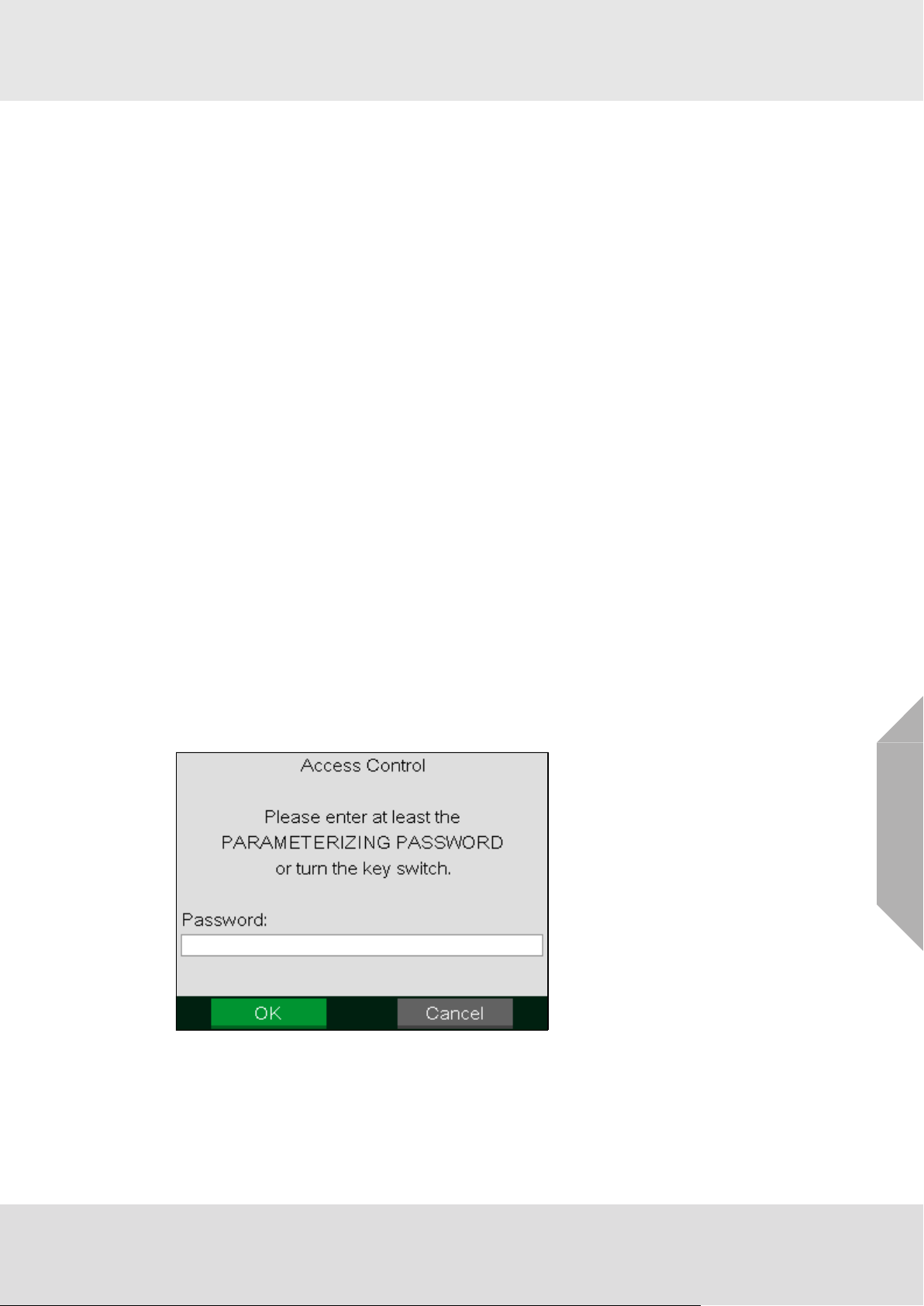
3.2 Access Authorisation
In the various windows, data can be displayed and entered and certain actions can be initiated by
using the touch screen (e.g., starting a calibration procedure). However, editing items or initiating
actions requires access authorisation by entering the password required for the control level or
operating a keyswitch, if fitted.
Three user groups with different password control levels are defined:
• Maintenance
• Parametrisation
• Configuration
Fig. 4 Access control
If the user wants to change a value or press a button when the required authorisation is not yet
issued, the appropriate password must be entered in the pop up window or the key switch must
be activated. Password authorisation remains in effect until measurement mode is activated either
through user input or automatically due to inactivity of 3 minutes or alarms.
SUPREMATouch
GB
19
Page 20

System Operation
If a user with modification authorisation is logged in at the PC and there has not been any communication between the PC and the SUPREMATouch system for more than 5 minutes, password
authorisation will automatically expire.
While SUPREMA Manager is connected to the SUPREMATouch, it is not possible to
simultaneosly change settings via the MDO.
Whether password authorisation is still in effect is indicated by a small lock symbol in lower right
corner of each password controlled window.
Lock symbol
The system is delivered with the default password AUER for all three password levels. MSA
recommends to change the passwords when accessing the SUPREMATouch for the first time.
In the Measure and Diagnosis submenus, data is only displayed, password access control is not
required.
Changing the Password
The password must have a minimum of four characters and may not have more than eight. Any
symbol from the ASCI character set can be used. The password is case-sensitive.
If no password at all is wanted, the password can be deleted by entering nothing instead of a new
password. Authorisation can then be granted only by using the key switch. In this case, an additional security dialog is initiated with the warning that the approval of the system is revoked in the
event of unauthorized changes.
To change a current password/create a new password, carry out the following:
(1) Select the corresponding password field in the Setup/System menu.
Enter the current password or actuate the key switch.
(2) After entering the password or actuating the key switch, leave the window with the OK button.
When the key switch was actuated, it can be released again after leaving the password
window.
(3) Enter the new password in the Password and Confirmation fields of the Setup/System menu.
(4) Confirm the new password with OK.
To replace a forgotten password, a higher-level password can be entered. If the current
parameterisation password is also lost, a new password can be entered by actuating the
key switch. If there is no key switch to close, connect terminal contacts 1 (GND) and 2
(PSW) on the MST module with a wire jumper, provided that these terminals can be
accessed safely.
3.3 Measure Menu
When the system configuration is successfully completed, the Measure menu will appear automatically after the system is started. For display of measured values, it is possible to choose from
different display types:
• List (default after start-up)
•Bars
•LEDs
•Groups
Displayed measurement and status values are updated once per second.
Unlike the common alarm LEDs on the MDO front panel, the touch screen display of alarms and
failures does not flash.
GB
SUPREMATouch
20
Page 21
System Operation
If the user is in the List, Bars or LEDs window and does not tap any key for 60 seconds, the window
automatically starts scrolling (one page per 5 seconds).
(1) To scroll through the list manually use the arrow buttons in the lower left corner of the window
or move the list while touching it.
For all display types, it is possible to manually switch between different modes of displaying the
measured information. In one mode all inputs are shown, in the other modes only the inputs in
alarm or fail status are shown.
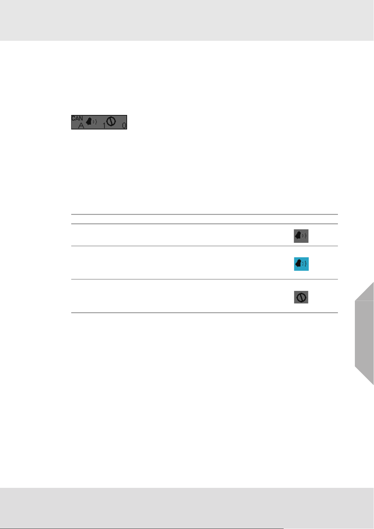
(2) To switch between modes touch the bell or the sign symbol in the lower right corner of the
measure window.
If one of these selection modes is chosen, the corresponding symbol has a blue background.
The number of measuring points in alarm and in fail and the CAN bus, A or B, currently
selected as the information source is also shown in this area.
It is possible to switch to the CAN bus by touching the CAN symbol. If the CAN bus is manually
selected, the CAN symbol has a blue background. If the CAN bus is automatically selected, the
CAN symbol has a grey background.
Modes
Mode Display Indicated by
All Inputs
Alarm Inputs
Fail Inputs
In this mode, all the measured inputs in the system are
displayed. The inputs are arranged by their input number.
When no alarm is triggered, this mode behaves like the All
Inputs Mode.
As soon as alarms are triggered, only the inputs in alarm are
displayed, sorted by the time of alarm triggering.
When no measuring point is in fail status, this mode behaves
like the All Inputs Mode.
As soon as at least one input is in fail status, only the inputs in
fail status are displayed, arranged by their input number.
GB
SUPREMATouch
21
Page 22
System Operation
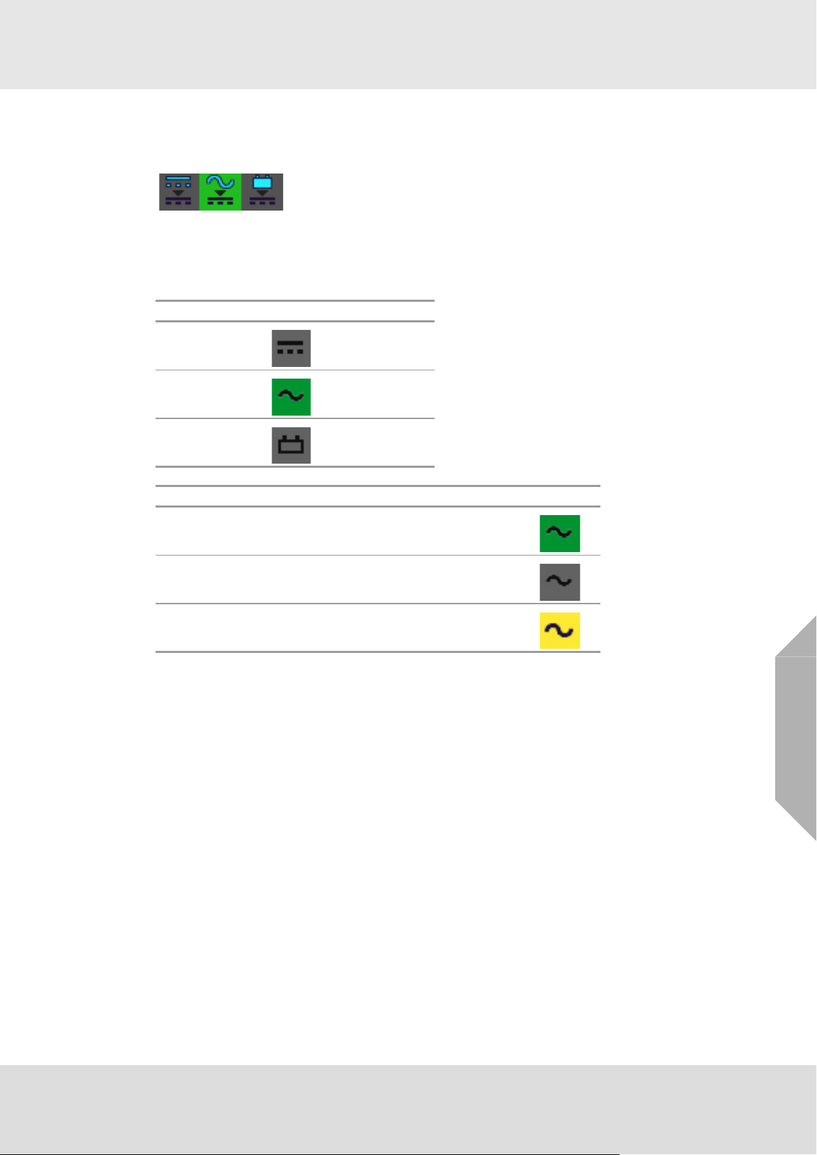
Power Supply Indicator
The power supply indicator gives a quick overview of the current status of the power supply of the
system.
Fig. 5 Power Supply Indicator
By tapping on the Power Supply Indicator, a window with information on the measuring values of
all transmitter/detector input nodes appears.
The 3 different power supplies are indicated with 3 different symbols.
Power Supply Symbol
External
Internal
Battery supply
Status (indicated by background colour)
good:
not configured =
failure =
connected, the voltage is below 30 V and
above 21V (for battery above 22 V)
=
GB
SUPREMATouch
22
Page 23
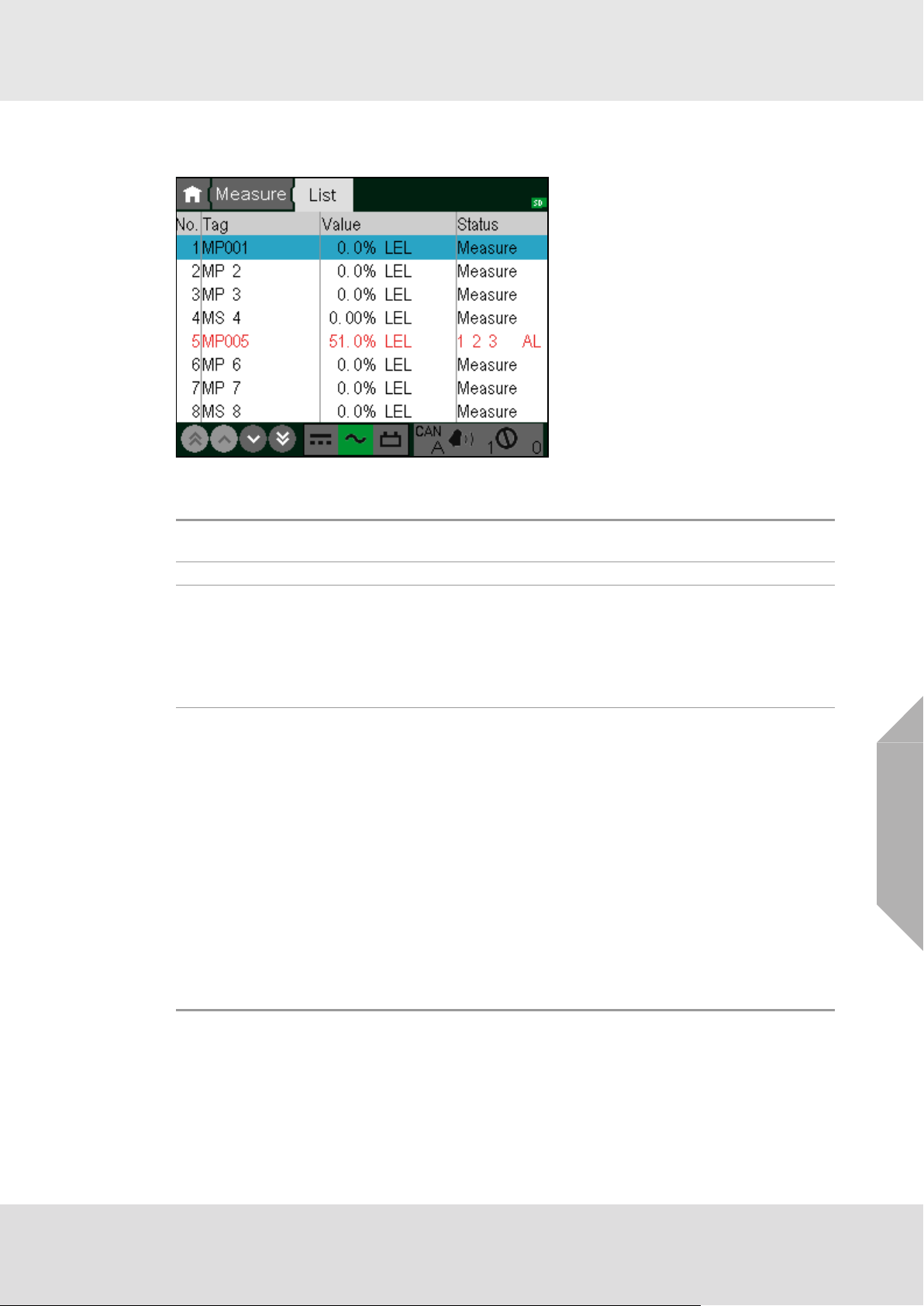
List Window
In this window, the current input data is displayed as a text list.
Fig. 6 List display (with a measuring point in Alarm)
The following input data is shown in this display:
System Operation
No.
Tag The customer defined input description.
Value
Status
The number of measured input in the system. This number is defined by the system
configuration.
Numerical value and dimension of measurement.
The measured values are displayed in intervals of 1 second, as long as they are
within measuring range. If measuring range is exceeded, the highest value reached
is retained.
In case of signal fail or an alarm suppression (during the warm-up period of specific
sensor types), dashes are displayed instead of the measured value.
Current status of the input. The status is updated at intervals of 1 second.
The following values can be displayed:
•Measure
• Calib. (Measurement point in calibration mode)
• Inhibit (Measurement point inhibited)
• Overflow (Measured value above full scale)
• SignalErr. (Measured value below measurement range, or value missing)
• SystemErr. (It was not possible for the MDO to get the measured value)
• PA-failed (Preadjustment error)
• For specific sensor types, text can be defined for special statuses. These are
labelled with F: (e.g. F:OpticErr).
• suppressed (Alarm suppressed during warm-up period of specific sensor types)
• alarms 1, 2, 3 and 4
• Free (measuring point has not been parameterized)
GB
SUPREMATouch
23
Page 24
System Operation
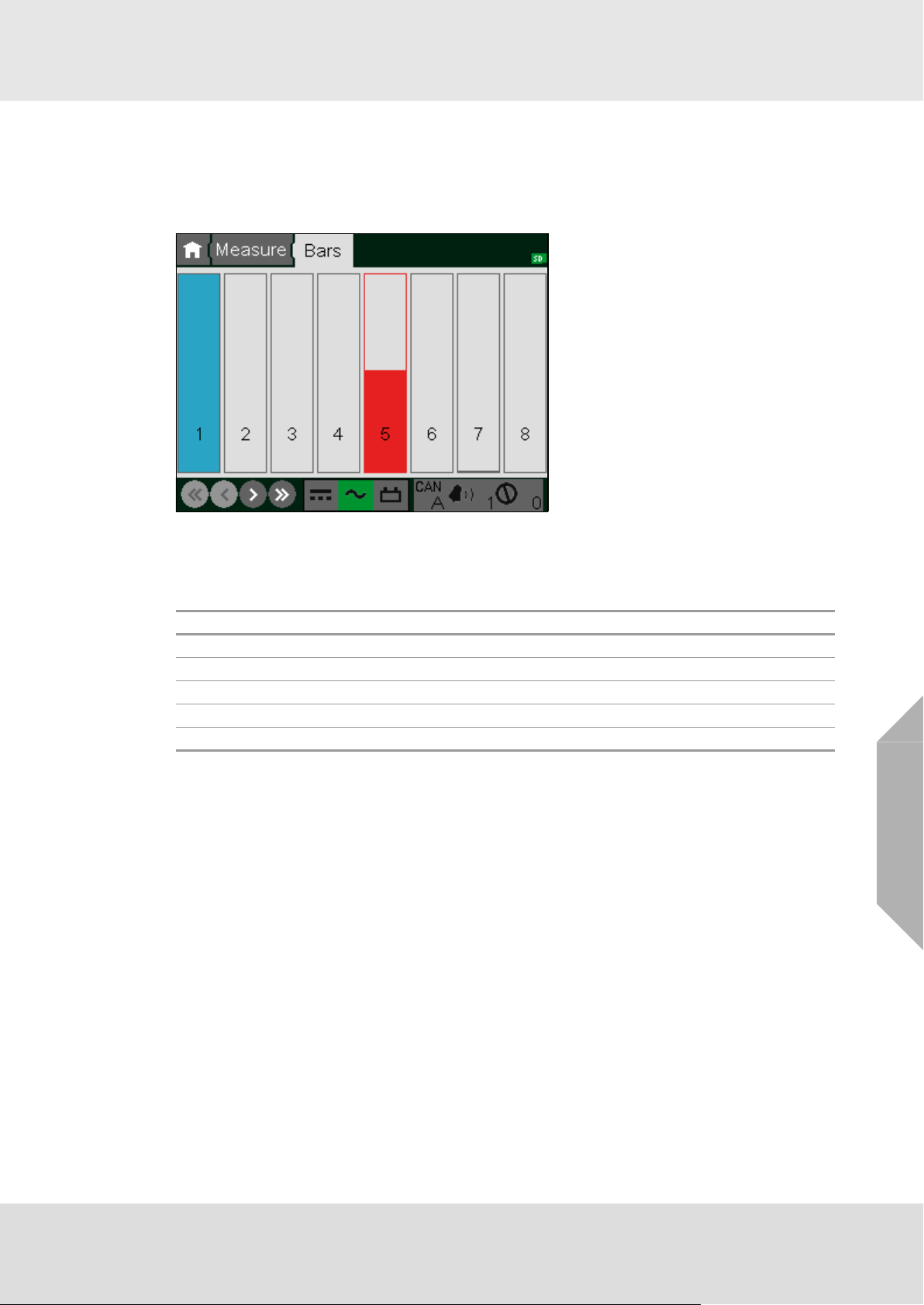
Bar Display
This display shows the measured values as vertical bars, where each bar represents the relative
measurement value of an input with respect to full scale. The value range that can be displayed
is 0–100% of full scale.
The corresponding input number is shown in each bar.
Fig. 7 Bar display
Measured values are displayed as solid bars. In error-free operation with no alarms, the bars are
grey. Any alarm will cause the corresponding bar to change to red. When a status message occurs
for an input, the bar is shown only as an outline with a status identification letter.
Letter Meaning
I Inhibit
C Calibrating
F Fault (measuring value below range, measuring value missing)
O Measurement range exceeded (overflow)
S Alarm suppressed (during the warm-up period of special sensor types)
If an input is not configured no bar is displayed in that column.
GB
SUPREMATouch
24
Page 25

System Operation
LED Display
This window shows the status values of the inputs as LEDs. Under each LED column the corresponding input number is shown. In redundant systems, the information is shown separately for
each CAN bus.
• LED off (grey): not inhibited, no alarm, no failure
• LED on: inhibited, alarm, failure
If an input is not configured no LEDs are displayed in that column.
Fig. 8 LED Display
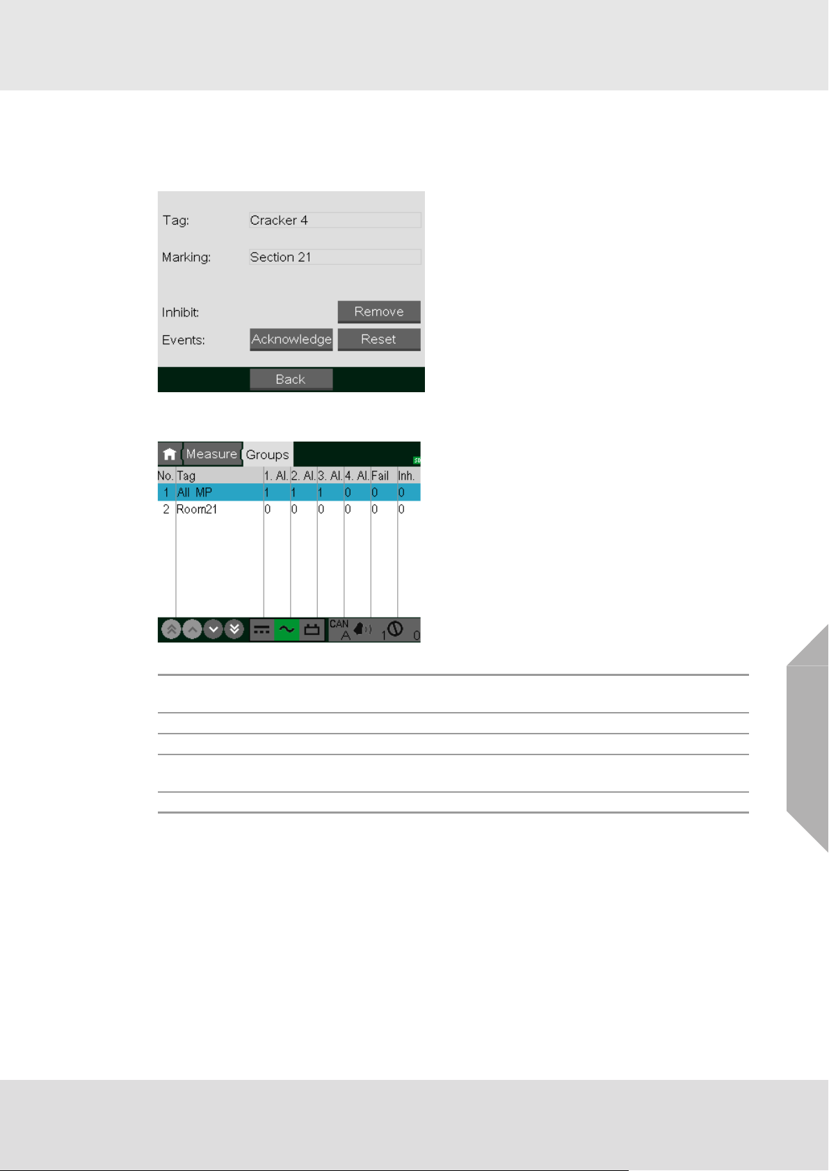
Measuring Information
Any item in the measuring list can be selected with a double-tap. A selected item is highlighted in
blue. By double-tapping an item in the List/Bar/LED window, a window pops up that shows additional information on the selected item and gives the option to inhibit, acknowledge or reset this
input. Tapping on the shown chart enlarges the chart to full screen. Tapping again reduces the
size again.
Fig. 9 Measuring information
GB
SUPREMATouch
25
Page 26
System Operation
Group Information
Any item in the group list can be selected by tapping it. A selected item is highlighted in blue. By
double-tapping an item, a window pops up that shows additional information on the selected item
and gives the option to de-inhibit, acknowledge or reset all measuring points of this group.
Group View
In this window, the status of each group of measuring points is displayed as a text list.
The following status information is shown in this display:
No.
Tag The customer defined group description.
n. Al. Number of measuring points in this group which have the n-th alarm pending.
Fail
Inh. Number of measuring points in this group which are inhibited or in calibration mode.
The number of the group in the system. This number is set by the system and cannot
be changed by the user.
Number of measuring points in this group which have a signal fail pending or are
suppressed.
GB
SUPREMATouch
26
Page 27
Entering System Parameters
4 Entering System Parameters
The TFT display touch screen is used to select data for editing or to enter data. At the top of the
screen is a breadcrumb menu where an item can be selected by simply tapping it. Tapping an item
more left the current item, returns to the related menu level. Tapping on the house symbol returns
to the root menu. Each menu level is represented by a mask with different icons for each menu
entry which can be selected by tapping it.
Fig. 10 Menu list and input
All types of controls are used by just touching them. The following types of interactive controls are
available:
Buttons
Buttons trigger actions. They are activated by tapping them.
Selection Fields
Selection fields contain a list of possible values that can be selected. By tapping an item, a new
window pops up and shows all available values. To select a new value, tap it and press the OK
button.
GB
Fig. 11 Selection window
SUPREMATouch
27
Page 28
Entering System Parameters
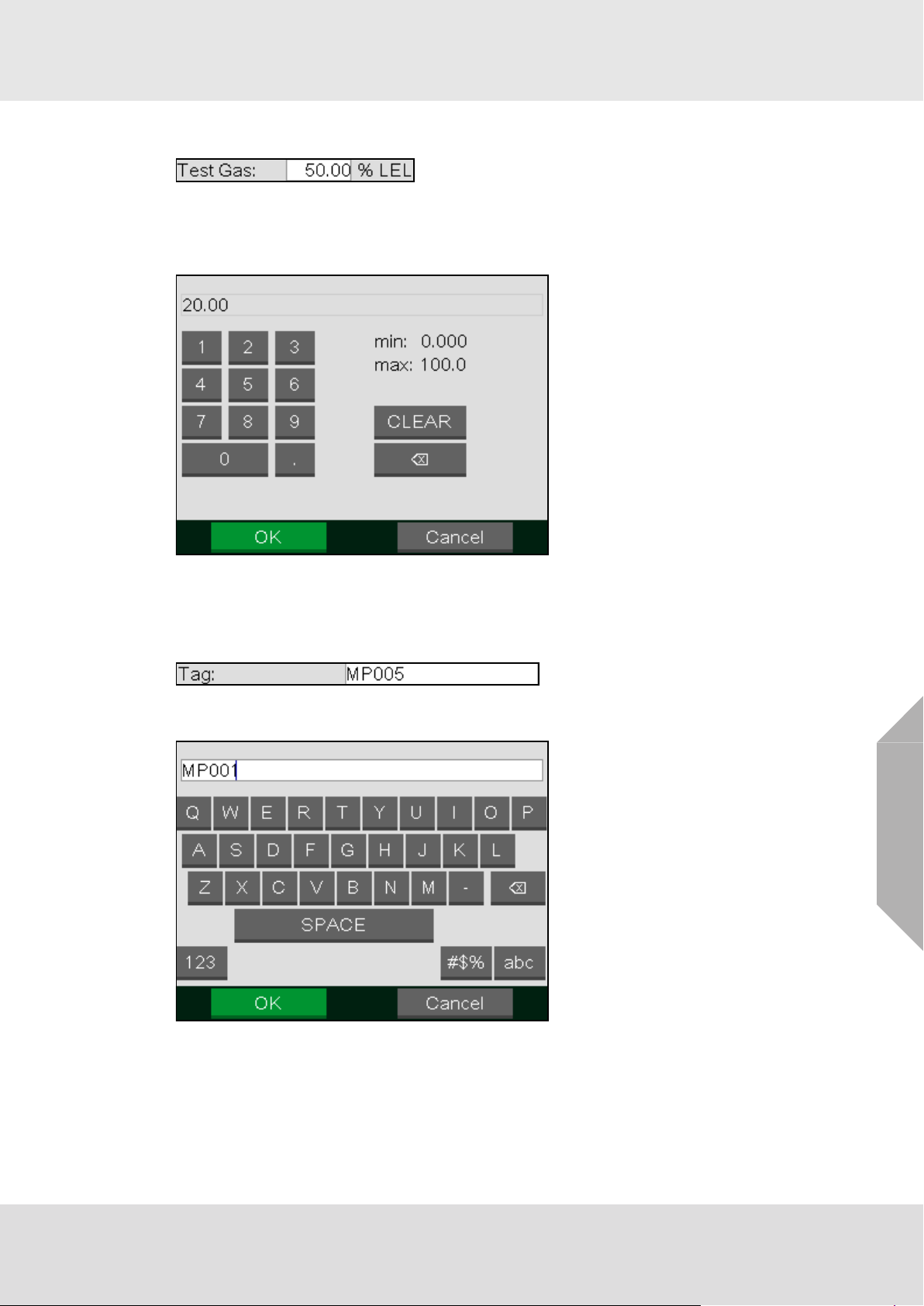
Number Fields
Number fields can contain integers or decimal numbers that can be changed. When tapping the
field, a new window pops up that allows a new value to be entered. To store a new value, press
the OK button. It is not possible to store a value if it is not in the range indicated by the min and
max values.
Fig. 12 Number input
Pressing the CLEAR button deletes the entered number. Pressing the button deletes the last
digit.
Text Fields
Text fields can contain numbers, letters and special characters that can be changed by the operator. By tapping the field, a new text editor window pops up. To save the text, press the OK button.
GB
Fig. 13 Text editor window
The new character is always inserted at the position indicated by the cursor. To change the cursor
position, tap the required new position. Pressing the button deletes the character in front of the
cursor.
SUPREMATouch
28
Page 29
Entering System Parameters
Display Fields
Display fields display information that cannot be changed. They are not affected by tapping it.
Check Boxes
Check boxes represent options that can be enabled or disabled. Tapping the box switches
between enabled and disabled status.
An enabled check box shows a cross. A disabled check box is empty.
Lists
Fig. 14 List
Lists display information. No parameters can be entered. To scroll through the list, use the
scrollbar or press down and drag the list in the desired direction (up/down or left/right).
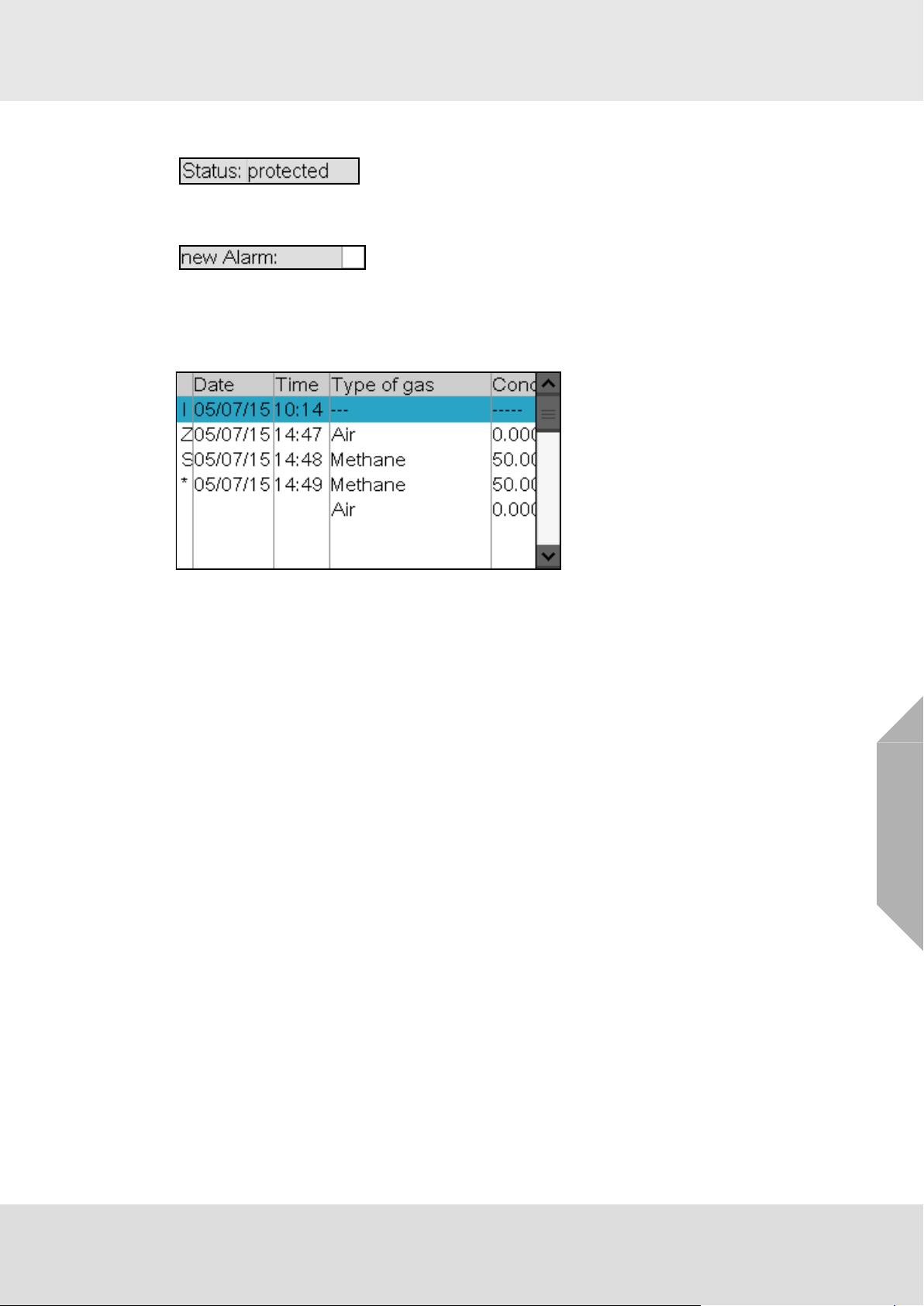
In some lists (e.g. SystemEventList), additional information about the selected item can be
displayed by double-tapping the item.
GB
SUPREMATouch
29
Page 30

Entering System Parameters
4.1 Setup Menu
Using the Setup menu, the operator can set parameters for sensor inputs and relay outputs, as
well as other system parameters. Although data can be retrieved and displayed, changing and
activating of actions is possible only after entering the parameterisation password or operating the
key switch. The menu is structured as follows:
Inputs &
Outputs
Sensors
Measuring Points
Relay Outputs Display
System
Groups Time
Switch Inputs TCP/IP
Head Params
Logging
Dimensions Printer
Status Texts
Lin Tables
Gas Names
Passwords
SD card
Assignment
Ranges
Allocation
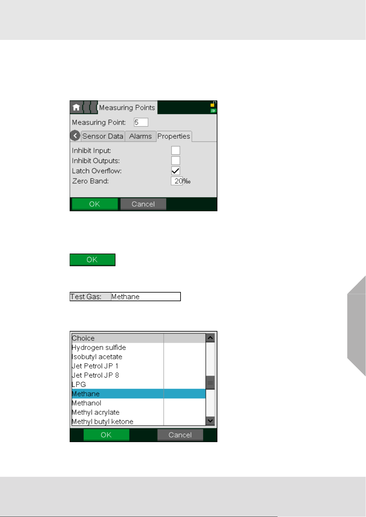
Measuring Points Submenu
This window shows all parameters that describe a sensor input. Input parameters can be viewed
and changed here.
The Measuring Point window is divided into four subwindows:
• Information
• Sensor data
•Alarms
• Properties
GB
SUPREMATouch
30
Page 31

Entering System Parameters
Fig. 15 Measuring Point Setup
The following paragraphs describe the functions of the individual window fields and buttons. The
first fields described are identical in all subwindows.
All parameter changes using the window fields described below apply to the inputs
selected in that field.
Field Field Type Function
List of all configured sensor inputs.
If an input is displayed that has not yet been set up, the settings
from the last input setting remain or default values are used as
Measuring
Point
Information,
Sensor Data,
Alarms and
Properties
OK Button
Cancel Button
Clear Button
Selection field
Button Press this button to display the corresponding subwindow.
the preliminary settings for the input of certain fields. This field
can be accessed without a key switch or password if an input is
entered for which input parameters have already been set. If a
number is entered that has not been used before, authorization
with a password or key switch is required.
Tap this button to accept the settings entered in all subwindows
for the selected input. After tapping the button, the parameters
are immediately checked to see if they are valid. If the parameters are valid, they become part of the system’s parameter set.
If they are not valid, a warning appears.
Press this button to discard the settings entered in all subwindows for the selected input.
Press this button to delete the parametrization of the selected
input. Default values are used as the preliminary settings. The
delete function will not work if the input is being calibrated or
linked with a relay output.
GB
SUPREMATouch
31
Page 32

Entering System Parameters
Information Subwindow
The Information subwindow contains general data on the selected input.
Field Field Type Function
Tag
Marking
Sensor
Serial No.
Installation
Area
Sensor Data Subwindow
The Sensor data subwindow contains settings for the sensor at the selected input.
text, 10 characters;
empty by default
text, 20 characters;
empty by default
text, 10 characters;
empty by default
text, 20 characters;
empty by default
Enter a customer specific designation for the selected input
Enter a customer specific description for the selected input.
Enter serial number of the input device for the selected input.
Enter a customer specific description of the installed location
of the input device for the selected input.
Fig. 16 “Sensor data” subwindow
Field Field Type Function
Sensor Type
Range
Dimensions
Meas. Gas
Zero Gas
(Zero Gas)
Valve No.
Selection,
empty by
default
Selection,
default: 100
Selection,
default: %LEL
Selection,
empty by
default
Selection,
empty by
default
Selection,
empty by
default
Contains a list of supported input device types.
Set the type of device used for the selected input.
Contains a list of supported measurement ranges.
Set the measurement range that applies for the selected input.
Contains a list of supported measurement dimensions.
Set the measurement dimension for the selected input.
Contains a list of supported gases.
Set the gas to be measured with the sensor for the selected
input.
Contains a list of ‘Zero’ gases used to calibrate the zero-point of
the gas sensors.
Set the zero gas that will be used to calibrate the gas sensor for
the selected input.
Contains a list of available outputs that can be used as zero gas
valve output.
This valve will be used during the calibration of the input. If no
valve should be used, select free.
GB
SUPREMATouch
32
Page 33

Entering System Parameters
Field Field Type Function
Selection,
Test Gas
(Test Gas)
Valve No.
Auto Button
Alarms Subwindow
Alarms
Alarms can be latching or non-latching (also see Measuring Points submenu).
Non-latching alarms:
When a signal exceeds the alarm threshold, a new alarm is triggered and the corresponding LED
flashes at a frequency of 0.5 Hz. Pressing the ACKNL (acknowledge) key makes the LED change
to ‘steady state’. When the signal is below the alarm threshold, the LED will turn off, regardless of
whether the alarm has been acknowledged or not. For non-latching alarms, the RESET key has
no effect.
Latching alarms:
When a signal exceeds the alarm threshold, a new alarm is triggered and the corresponding LED
flashes at a frequency of 0.5 Hz. Pressing the ACKNL (acknowledge) key makes the LED change
to ‘steady state’. When the signal no longer exceeds the alarm threshold, the LED remains in
‘steady state’ if the alarm has been acknowledged, or in the ‘flashing state’ if the alarm has not
been acknowledged. If the signal no longer exceeds the alarm threshold and the alarm has been
acknowledged, the LED is extinguished by pressing the RESET key. If the signal still exceeds the
alarm threshold, pressing RESET has no effect.
In the Alarms subwindow, parameters can be set for up to four alarm levels for the selected input.
A limit value can be set for each alarm to trigger either on a rising or falling input signal. In addition,
relay outputs can be selected to operate if an alarm occurs. For every alarm, latching or non-
latching parameters can be set.
empty by
default
Selection,
empty by
default
Contains a list of supported ‘Test gases’ to calibrate the spanpoint of the sensors.
Set the test gas that will be used to calibrate the sensor at the
selected input.
Contains a list of available outputs that can be used as test gas
valve output.
This valve will be used during the calibration of the input. If no
valve should be used, select free.
Using this button, certain fields are filled with data that is automatically detected, (i. e. read-out via HART).
Fig. 17 “Alarms” sub-window
SUPREMATouch
GB
33
Page 34

Field Field Type Function
Upper
(Rising/
Falling
Alarm)
Latched
Limit
Relay
Check Box, set
by default
Check Box, not
set by default
decimal
number, range
is selected
range of
measuring
point; 20, 30,
40, 50 by
default
Selection,
cleared by
default
For each alarm, this check box sets the alarm to trigger when
the signal is rising or falling. If this box is checked it is a rising
alarm, if not checked, it is a falling alarm.
The alarm is latching if the box is checked, if the box is not
checked, it is non-latching.
This parameter has an effect on the behaviour of the MDO front
panel LEDs, on the information in the Measure menu, and on
the relay outputs assigned to an alarm.
A limit value can be set for each alarm of the selected input, to
trigger on either a rising or falling input signal. This limit value
can be set in a range from 0 till the range value set in the subwindow Sensor Data.
It is also possible to deactivate an alarm:
Press the Clear button. A message box appears. Confirm with
OK to delete the contents of the field.
These fields contain a list of available relay outputs. The relay
outputs that will be used for the individual alarms at the selected
input can be set here. After selecting a relay output, the relay
output assignment window opens up.
Entering System Parameters
“Properties” subwindow
The Properties subwindow contains behavioral data on the selected input.
Fig. 18 “Properties” subwindow
GB
SUPREMATouch
34
Page 35

Entering System Parameters
Field Field Type Function
Inhibit
Inputs
Inhibit
Outputs
Latch Overflow
Zero Band
Relay Output Assignment Window
This is not a subwindow of the Measuring Point menu, but an independent window that can only
be reached from the Measuring Point menu. It is used to assign relay outputs to the input selected
in the Measuring Point menu. This window also provides the same function as the Relay Output
window.
The top three rows of the menu cannot be accessed here and are only shown for information. The
behavior of a relay output depends on its parameter settings and the settings of the appropriate
measuring points.
Check Box, not
set by default
Check Box, not
set by default
Check Box, set
by default
decimal number,
range is 0..50‰;
20‰ by default
If enabled, the selected input cannot trigger alarms.
If enabled, assigned outputs will not be activated in the
event of an alarm or failure of selected measuring points!
During a multiple assignment (Voting), the corresponding
measuring point is ignored when assessing the status. If
enabled for at least one of the measuring points, the inhibit LED
on the MDO as well as the common alarm relay 'Inhibit' starts
flashing with a frequency of 0.5 Hz.
If enabled, overflows are latched. This option can not be
disabled for passive sensors.
Defines the size of a window around 0 where all measuring
values will be displayed as 0.
Fig. 19 Relay output assignment
The functions of the individual window elements are described below:
All parameter changes using the menu elements described below apply to the relay
output selected in the Relay field.
SUPREMATouch
GB
35
Page 36

Field Field Type Function
Contains a list of all available relay outputs. After an output
number is selected, the rest of the window is filled, if
settings have already been entered for that output.
If an output number is selected that has not been configured
before, the settings from the last displayed output remain
and are used as the preliminary settings for the new output.
This makes it easy to copy the settings from one output to
another. If an output is displayed that has not yet been
Relay Selection
text, 10 charac-
Tag
Normal run
blinking
New Alarm
Point based
voting
ters; empty by
default
Selection,
default is closedcircuit
Checkbox, not
set by default
Checkbox, not
set by default
Checkbox, not
set by default
configured, default values are used as the preliminary
settings.
This input field can be accessed without a key switch or
password if an output has been selected for which parameters have already been set. If a number is entered that has
not been used before, authorization with a password or key
switch is required.
When first opened, the field contains the relay output that
was last selected in the Measuring Point window.
Enter a customer-specific designation for the selected relay
output.
Set the operating mode for the selected relay output:
• Closed circuit (normally energized):
The relay coil is energized in the no alarm status and is
de-energized in the alarm status.
• Open circuit (normally de-energized):
The relay coil is de-energized in the no alarm status and
is energized in the alarm status.
If enabled, the relay flashes at a frequency of approx.
0.5 Hz when activated until the alarm is acknowledged. This
function doesn't work combined with the inhibit condition.
If enabled, the relay output selected can be set to the status
defined by the input field Normal Run by acknowledging the
selected conditions, even if the conditions are still pending.
If enabled, the counting for the voting is done by counting
the effected measuring points instead of the effected conditions.
Entering System Parameters
GB
SUPREMATouch
36
Page 37

Field Field Type Function
The value entered here applies to the configuration conditions described above. Optional status combinations
(alarm, fail, and inhibit) can be formed when the selected
relay output is configured. The number value selected here
determines how many of the conditions configured in the
control boxes must be met for the selected relay output to
be switched. The number of conditions entered in the check
boxes is displayed in the field beside the voting to be configured.
The following types of links can be formed in this manner:
Single link: (1-out-of-1):
Integer, range is
Voting (Alarm
Logic)
Al. 1-4 (1st-4th
Alarm)
Fail
Inhibit
OK Button
Cancel Button
Clear Button
1 to number of
selected conditions; 1 by
default
Checkbox, not
set by default
Checkbox, not
set by default
Checkbox, not
set by default
Exactly one condition is set, and the value of 1 is entered as
the voting.
“OR” link: (1-out-of-m)
Multiple conditions are set, and the value of 1 is entered as
the voting, i.e., if any one or more of the set conditions are
met, the relay output will be switched. Parameters for a
global alarm or common alarms can be set in this manner.
“AND” link: (m-out-of-m)
The value entered for the voting corresponds to the number
of set conditions, i.e. all of the set conditions must be met
for the relay output to be switched.
Voting link: (n-out-of-m)
If ‘m’ conditions are set, and the value of ‘n’ is entered as
the voting, then the selected relay output will only be
switched if ‘n’ out of the ‘m’ conditions are met.
After each change of the voting conditions, the complexity
of the alarm logic is checked. If a certain level is exceeded,
a warning will be displayed or eventually the changes will be
rejected.
Enable to select the alarms that will cause the selected
relay output to trigger for the input shown in the Chan.
column.
If enabled, the selected relay output is switched when an
error (fault) occurs for the input displayed in the Chan.
column.
If enabled, the selected relay output is switched when the
input displayed in the Chan. column is inhibited.
Tap this button to accept the settings entered for the
selected relay output. After tapping the button, the parameters are immediately checked to see if they are valid. If the
parameters are valid, they become part of the system’s
parameter set. If they are not valid, a warning appears.
Pressing this button discards the settings entered for the
selected relay output.
Pressing this button deletes all of the parameters for the
selected relay output. The output then returns to the status
it was before it was set up the first time.
Entering System Parameters
GB
SUPREMATouch
37
Page 38

Entering System Parameters
Relay Outputs Window
Parameter values for relay outputs can be viewed and changed here.
The functions of window are similar to the Relay Output assignment window described in the
previous section. There, starting from a particular input, a connection to a relay output was made.
In this menu, the setting conditions are configured starting from a particular relay output.
The behaviour of a relay output depends on its parameter settings and the settings of the appropriate measuring points.
Fig. 20 Relay output
The Relay Outputs window is divided into three subwindows:
• Information
• Sensor connections
• Relay connections
The following paragraphs describe the functions of the individual window fields and buttons. The
first fields described are identical in all three subwindows.
All parameter changes using the menu elements described below apply to the relay
output selected in the Relay field.
Field Field Type Function
Contains a list of available relay outputs. As the first 8 relay
outputs of the system are tied to the common messages,
the first relay output which can be configured is No. 9.
After an output number is selected, the rest of the window
is filled, if settings have already been entered for that
output. This input field can be accessed without a key
Relay Selection
switch or password if an output is selected for which parameters have already been set. If an output is selected that
has not been used before, authorisation with password or
key switch is required. If an output is displayed that has not
yet been configured, default values are used as the preliminary settings for the certain fields. This makes it easy to
copy the settings from one output to another.
GB
SUPREMATouch
38
Page 39

Field Field Type Function
The value entered here applies to the configuration conditions described above. Optional status combinations
(alarm, fail, inhibit, calib, suppressed) can be formed when
the selected relay output is configured. The number value
selected determines how many of the conditions configured
in the check boxes must be met for the selected relay output
to be switched. The number of conditions entered in the
check boxes is displayed in the field beside the voting to be
configured.
The following types of links can be formed in this manner:
Single link: (1-out-of-1):
Exactly one condition is set, and the value of 1 is entered as
Integer
Voting (Alarm
Logic)
OK Button
Cancel Button
Clear Button
the voting.
“OR” link: (1-out-of-m)
Multiple conditions are set, and the value of 1 is entered as
the voting, i.e., if any one or more of the set conditions are
met, the relay output will be switched. Parameters for a
global alarm or common alarms can be set in this manner.
“AND” link: (m-out-of-m)
The value entered for the voting corresponds to the number
of set conditions, i.e. all of the set conditions must be met
for the relay output to be switched.
Voting link: (n-out-of-m)
If ‘m’ conditions are set, and the value of ‘n’ is entered as
the voting, then the selected relay output will only be
switched if ‘n’ out of the ‘m’ conditions are met.
After each change of the voting conditions, the complexity
of the alarm logic is checked. If a certain level is exceeded,
a warning will be displayed or eventually the changes will be
rejected.
Tap this button to accept the entered settings for the
selected relay output. After tapping the button, the parameters are immediately checked to see if they are valid. If the
parameters are valid, they become part of the system’s
parameter set. If they are not valid, a warning appears.
Tapping this button cancels the settings entered for the
selected relay output.
Tapping this button deletes all of the parameters for the
selected relay output.
The output then returns to the status it had before being set
up the first time. Default values are used as the preliminary
settings for the input of certain fields.
Entering System Parameters
GB
SUPREMATouch
39
Page 40

Information subwindow
Fig. 21 Information subwindow
Field Field Type Function
Tag
Normal Run
(Normally ener-
gised/Normally
de-energised)
blinking
Point based
voting
New Alarm
Delay
Text, 10 characters; empty by
default
Selection,
default is closedcircuit
Checkbox, not
set by default
Checkbox, not
set by default
Checkbox, not
set by default
Integer, Range
is 0 to 10; 0 by
default
Enter a customer-specific designation for the selected relay
output.
Set the operating mode for the selected relay output:
• Normally energised (closed circuit): The relay coil is
energised in the no alarm status and is de-energised in
the alarm status.
The output delivers in the set-condition (Alarm, Failure)
a LOW-Signal, this is called a connected relay is not
energised. (The Normally energised principle)
• Normally de-energised (open circuit):
The relay coil is de-energised in the no alarm status and
is energised in the alarm status.
The output delivers in the set-condition (Alarm, Failure)
a HIGH-Signal, this is called a connected relay is energised. (The Normally de-energised principle)
If enabled, the relay flashes at a frequency of approx.
0.5 Hz when activated until the alarm is acknowledged. This
function doesn't work combined with the inhibit condition.
If enabled, the counting for the voting is done by counting
the effected measuring points instead of the effected conditions.
If this field is set, the relay output selected can be set to the
status defined by the input field Normal Run by acknowledging the selected conditions, even if the conditions are
still pending.
Defines a delay between the occurence of the switching
conditions for this output and the actual switching of the
output.
Entering System Parameters
GB
Time delays for relays should not be used for safety-relevant purposes. If the use
cannot be avoided, the minimum possible value for the given application must be set.
SUPREMATouch
40
Page 41

Sensor connections subwindow
Fig. 22 Sensor connections subwindow
Field Field Type Function
Al. 1-4 (1st-4th
Alarm)
Fail
Inhibit
Check box, not
set by default
Check box, not
set by default
Check box, not
set by default
Select the alarms that will cause the selected relay output
to be activated, for the input shown in the channel column
in the specific line.
If this condition is set, the selected relay output is activated
when an error (fault) occurs for the input shown in the
channel column in the specific line.
If this condition is set, the selected relay output is activated
when the input shown in the channel column in the specific
line is inhibited.
Entering System Parameters
SUPREMATouch
GB
41
Page 42

Field Field Type Function
The value entered here applies to the configuration conditions described above. Optional status combinations
(alarm, fail, inhibit, calib, suppressed) can be formed when
the selected relay output is configured. The number value
selected determines how many of the conditions configured
in the check boxes must be met for the selected relay output
to be switched. The number of conditions entered in the
check boxes is displayed in the field beside the voting to be
configured.
The following types of links can be formed in this manner:
Single link: (1-out-of-1):
Exactly one condition is set, and the value of 1 is entered as
Integer
Voting (Alarm
Logic)
the voting.
“OR” link: (1-out-of-m)
Multiple conditions are set, and the value of 1 is entered as
the voting, i.e., if any one or more of the set conditions are
met, the relay output will be switched. Parameters for a
global alarm or common alarms can be set in this manner.
“AND” link: (m-out-of-m)
The value entered for the voting corresponds to the number
of set conditions, i.e. all of the set conditions must be met
for the relay output to be switched.
Voting link: (n-out-of-m)
If ‘m’ conditions are set, and the value of ‘n’ is entered as
the voting, then the selected relay output will only be
switched if ‘n’ out of the ‘m’ conditions are met.
After each change of the voting conditions, the complexity
of the alarm logic is checked. If a certain level is exceeded,
a warning will be displayed or eventually the changes will be
rejected.
Entering System Parameters
SUPREMATouch
GB
42
Page 43

Relay connections subwindow
Maximum three relays can be connected in series.The acknowledgment status will be
handed over from the child relay to the parent relay. The blinking and new alarm configuration of the child relay are not relevant here.
Relays are treated as one event in voting, regardless of the settings in point based
voting.
Entering System Parameters
Fig. 23 Relay connections subwindow
Field Field Type Function
Channel
Groups Window
Parameters for groups of measuring points can be viewed and changed here.The Groups window
is divided into two subwindows:
• Information
• Measuring Points
The following paragraphs describe the functions of the individual window fields and buttons.
The following fields described are identical in both subwindows:
Field Field Type Function
Group No. Selection Field
OK Button
Cancel Button
Clear Button
Checkbox, not
set by default
If this condition is set, the selected relay output is activated
when the switching condition occurs for the relay shown in
the channel column in the specific line.
List of all available groups.
After a group number is selected, the available space of the
window is filled with data.
Press this button to accept the settings entered in both subwin-
dows for the selected group. After tapping the button, the parameters are immediately checked to see if they are valid. If the
parameters are valid, they become part of the system's parameter set. If they are not valid, a warning appears.
Press this button to discard the settings entered in both subwindows for the selected group.
Press this button to delete all parameters for the selected group.
The group will then return to the status it had before being set up
the first time.
GB
SUPREMATouch
43
Page 44

Entering System Parameters
"Information" subwindow
The Information subwindow contains general data of the selected group.
Fig. 24 Information subwindow
Field Field Type Function
Tag
Marking
Calibratable
Text, 10 characters; empty
by default
Text, 20 characters; empty
by default
Check Box, not
set by default
Enter a customer specific designation for the selected
group.
Enter a customer specific description for the selected
group.
Setting this check box allows to use this group for group
calibrations. A group can only be set as calibratable when
ranges and dimensions of the measuring point belonging to
this group are compatible.
GB
SUPREMATouch
44
Page 45

Entering System Parameters
"Measuring Points" subwindow
The Measuring Points subwindow contains a list of measuring points belonging to this group.
Each measuring point can belong to more than one group.
Fig. 25 Measuring points subwindow
Field Field Type Function
>> Button
<< Button
List List This list shows all measuring points currently belonging to this group.
Switch Inputs Window
Parameters for switch inputs can be viewed and changed here.
Opens a list of all measuring points. The selected measuring point is
added to the group with OK.
Pressing this button deletes the measuring point currently selected in
the list.
GB
Fig. 26 Switch Inputs Window
Field Field Type Function
List of all configured switch inputs.
Input No. Selection Field
Text input,
Tag
10 characters;
empty by default
After a group number is selected, the rest of the window is filled
with data.
Enter a customer specific designation for the selected group.
SUPREMATouch
45
Page 46

Field Field Type Function
List of all available commands for switch inputs.
Command Selection Field
Group Selection Field
OK Button
Cancel Button
Clear Button
Password
This window displays parameters that affect the entire system.
Commands: reset and acknowledge of single measuring points,
single measuring point groups, all events, power faults.
Power fault has no effect in standard operation mode.
List of all available entities (e.g. measuring points or groups)
this command should be applied to.
Press this button to accept the settings entered for the selected
switch input. After tapping the button, the parameters are immediately checked to see if they are valid. If the parameters are
valid, they become part of the system's parameter set. If they
are not valid, a warning appears.
Press this button to discard the settings entered for the selected
switch input.
Press this button to delete all parameters for the selected switch
input. The switch input will then return to inactive status.
Entering System Parameters
Fig. 27 Password
Field Field Type Function
Text input,
Password/
Confirmation:
OK Button
Cancel Button Tapping this button cancels the settings entered.
8 characters;
AUER by
default
See chapter
2.8 "Safety Concept"
Tap this button to accept the settings entered. After the button
is tapped, the parameters are immediately checked to see if
they are valid. If the parameters are valid, they become part of
the system’s parameter set. If they are not valid, a warning
appears.
SUPREMATouch
GB
46
Page 47

Entering System Parameters
Display
This window displays parameters that affect the entire system.
Fig. 28 Display
Field Field Type Function
Selection,
Language
Buzzer
Dimming
Signal if Inhibited
Operating
Mode
OK Button
Cancel Button Tapping this button cancels the settings entered.
English by
default
Number Input,
Range is 0 to
100; 100 by
default
Number Input,
Range is 0 to
100; 100 by
default
Selection,
pass by
default
Display, Standard by
default
Set the language for the user interface (GUI).
Sets the loudness of the internal beeper.
Sets the dimming of the display.
If a MAO module is used to output sensor signals, there are
three different ways of analogue signal behavior for inhibited
inputs:
• pass: The received measurement values are sent on.
• hold: The last measured value before inhibiting occurred is
retained.
• maintain: The signal goes to the maintenance level (corresponds to 3.0 mA).
The setting is essential for all measuring points in the whole
system.
Shows the current operating mode of the SUPREMATouch
system. Only two operating modes are available:
‘Standard’ for all countries except China and ‘GB16808-2008’
which is only for use in China. All information, including the
approval information in this manual refer to the Standard operating mode.
Tap this button to accept the settings entered. After the button
is tapped, the parameters are immediately checked to see if
they are valid. If the parameters are valid, they become part of
the system’s parameter set. If they are not valid, a warning
appears.
GB
SUPREMATouch
47
Page 48

Entering System Parameters
Time Window
This window displays the date and time of the system.
Fig. 29 Date/Time
Field Field Type Function
Date and time are set by tapping the input field and entering the
Date/Time
Time zone
DST mode
Synchronization
Update now Button Tapping this button starts a time synchronization immediately.
(S)NTP Server
Last update Static
OK Button
Cancel Button Tapping this button cancels the settings entered.
Date/Time
input
Selection,
UTC by
default
Selection,
none by
default
Checkbox, not
set by default
Text, 40 characters; empty
by default
new date and time in the date/time field.
After this window is closed, the new date and time is displayed,
but it does not become valid until the (OK) button is tapped.
Tap this field to select the time zone. The correct setting of the
timezone is required for the automatic time synchronization
function.
Tap this field to select and activate the automatic adjustment for
daylight saving time. This function works independent for the
time synchronization, but the correct setting of is required for the
automatic time synchronization function.
Activating this field activates the automatic time synchronization.
This field defines the time server to be used for automatic time
synchronization. It is possible to define the time server using a
IP address or a server name. When using a server name, a valid
DNS server has to be set in the TCP/IP window.
This field gives information about the last successful time
synchronization.
Tap this button to accept the entered settings. After tapping the
button, the parameters are immediately checked to see if they
are valid. If the parameters are valid, they become part of the
system’s parameter set. If they are not valid, a warning appears.
GB
SUPREMATouch
48
Page 49

Entering System Parameters
TCP/IP window
Parameters for TCP/IP connections can be viewed and changed here. Contact the responsible IT
department to get valid data if required.
Field Field Type Function
IP input,
IP Address
Subnet Mask
Standard
Gateway
DNS
MAC Address Static This field shows the MAC address of this device (MDO20).
Ok Button
Cancel Button
192.168.10.1
by default
IP input,
255.255.255.
0 by default
IP input,
empty by
default
IP input,
empty by
default
This field shows and changes the IP address of the MDO.
This field shows and changes the subnet mask of the MDO.
This field shows and changes the IP address of the standard
gateway. The standard gateway is used by the MDO to access
IP addresses outside the own subnet.
This field shows and changes the IP address of a domain
name server. The domain name server is used by the MDO to
translate domain names into IP addresses.
Press this button to accept the settings entered for the selected
TCP/IP settings. After tapping the button, the parameters are
immediately checked to see if they are valid. If the parameters
are valid, they become part of the system's parameter set. If
they are not valid, a warning appears.
Press this button to discard the settings entered for the TCP/IP
settings.
GB
Sensors Submenu
Through the submenu Sensors, the parameters of the predefined remote sensors can be viewed
as well as set for some predefined parameter in specific ranges. The menu contains the following
items described consecutively in this section:
• Head parameters
• Status texts
• Gas names
• Ranges
• Dimensions
• Lin.- tables
• Assignment
• Allocation
SUPREMATouch
49
Page 50

Entering System Parameters
Head Parameters
Fig. 30 Head parameter
This window displays the significant parameters of the remote sensors. During normal operation
the SUPREMATouch software continuously checks the detector output signal sent to the
SUPREMATouch. In case the detector output signal falls below UA
below UA
exceeds UA
a fault indication will be set for this measuring point. In case the detector output signal
idle
an overflow will be indicated. Data fields that are not used for a specific remote
over
an inhibit indication, and
min
sensor are empty.
It is possible to enter user specific data for some active remote transmitters (4–20 mA signal). For
this purpose, the following fields can be changed: Name (English and local language), UA
UA
idle
, UA
over
and T
. The ID of modifiable remote sensors begins with the value 10000 and
supp
min
,
their status is displayed as changeable.
Field Field Type Function
ID (Remote sensor
ID)
Status (Status of
this data cell)
Selection A remote sensor can be selected by its ID
Displays the status of the cell used for data saving. If this
Display
status is protected, then no data can be changed and the
following input fields are simply display fields.
In these fields, the name of the remote sensor is displayed in
both supported languages. The remote sensor can be
2 x Name (Head
name in English
(upper) and local
language (lower)
Text, 16
characters
selected as Sensor type in the setting of the measuring points
through these names.
The user can freely define the names in changeable remote
sensors. They must be unique, that is, no name can be given
twice. If a name is given for only one language, the same
name can also be used for the other language while saving it.
To leave empty, press clear
UA
(Limit for
min
“suppressed”)
Number
(integers)
Adjusting
range: 50–
350
This field displays the maximum signal UA for the status
suppressed. Measuring values below this limit value are
displayed as suppressed. If field is empty (tap Clear in the
number input window), then this status will not be tested.
This value can only be set for the three user-changeable data
sets.
GB
SUPREMATouch
50
Page 51

Field Field Type Function
UA
(Limit for
idle
signal fail)
UA
(Limit for
over
“overflow”)
Number
(integers)
Adjusting
range: 50–
350, must
be < UA
Number
(integers)
Adjusting
range:
2000–2200
This field displays the maximum signal UA for the status
signal fail. Measuring values below this limit value are
displayed as signal fail.
This value can only be set for the three user-changeable data
sets.
min
This value defines the sensor signal UA of the remote sensor
for the measuring range overflow display. Measuring values
above this value are displayed as overflow.
This value can only be set for the three user-changeable data
sets.
The warm-up time in seconds can be set here. This specifies
how long a sensor will remain in the warm-up status (display
suppressed) after it has been switched on. This time is necessary because different sensors need a different length of time
to warm up and the correct measuring value is displayed.
This value can only be set for the three user-changeable data
T
(Warm-up
supp
period)
Number
(integers)
Adjusting
range: 10–
300
sets.
OK Button
Cancel Button
By tapping this button, the completed settings are applied to
the selected head.
By tapping this button, the completed settings of the selected
head are canceled.
Entering System Parameters
Status Texts
Fig. 31 Status texts
Use this window to define sensor type specific texts for specific signal ranges.
These are displayed in the measuring value list with a letter F prefix. (e.g. F:OpticErr). Texts can
be defined for all remote sensors provided that ranges are specified for them. Texts can be
defined arbitrarily, the same texts are allowed for more than one sensor.
In addition, the user can freely define the signal ranges in the range from 0–400 mV for changeable remote sensors. However, the signal ranges must not overlap.
GB
SUPREMATouch
51
Page 52

Field Field Type Function
Sensor Selection
Status (Status
of this data
cell)
Status text
Range
OK Button
Cancel Button
Display
Text, 8 characters
Number input
This signal
range can be
set in a range
from 0–400.
The head, on which status texts should be put or for which it
should be changed can be selected with this field.
This field displays the status of the cell used for data saving. If
this status is protected, then data cannot be changed and the
following input fields are display-only fields.
Texts displayed in the measuring value lists can be entered
here. This text will be displayed if the measured value lies within
the specified signal range.
Lower and Upper limits of respective signal range. This is a
display-only field if the status for this sensor is protected.
By tapping this button, the completed settings are applied to the
selected head.
By tapping this button, the completed settings of the selected
head are cancelled.
Entering System Parameters
Gas Names
Fig. 32 Gas names
Use this window to view the provided protected gas names and to adjust some predefined
changeable gas names.
User defined texts can be entered. Identical names are not allowed and will be rejected with the
message Error: Name not unique!.
Field Field Type Function
ID (ID of this
gas name)
Status (Status
of this data
cell)
Name
(English)
Name (local)
Selection A gas name can be selected by its ID.
Displays the status of the cell used for data saving.
Display
Text, 20 characters
Text, 20 characters
If status is protected, then data cannot be changed and the
following input fields are display-only fields.
The English gas name can be entered here.
The gas name in local language can be entered here.
GB
SUPREMATouch
52
Page 53

Field Field Type Function
OK Button
Cancel Button
Measuring Ranges
By tapping this button, the completed settings for the selected
gas name are applied.
By tapping this button, the completed settings for the selected
gas name are cancelled.
Entering System Parameters
Fig. 33 Measuring ranges
Use this window to view the measuring ranges provided and to adjust some changeable
predefined changeable ranges.
User defined ranges can be selected. Identical values are not allowed and will be rejected.
The functions of the individual fields are described below:
Field Field Type Function
ID (ID of this
measuring
range)
Status (Status
of this data
cell)
Value
Text (English) Display The English value for this measuring range is displayed here.
Text (local) Display
OK Button By tapping this button, the completed settings are applied.
Cancel Button By tapping this button, the completed settings are cancelled.
Selection A measuring range can be selected by its ID.
This field displays the status of the cell used for data saving. If
Display
Text
Adjusting
range: 0.100–
99999
the status is protected, then data cannot be changed and the
following input fields are display-only fields.
The value for the measuring range can be set here.
In case of very high 5-digit measuring range the display may
show five arrows pointing upwards/downwards instead of the
measured value, if the value cannot be displayed with 5 digits.
The value in local language for this measuring range is
displayed here.
GB
SUPREMATouch
53
Page 54

Entering System Parameters
Dimensions
Fig. 34 Dimensions
Use this window to view dimensions provided and to adjust some predefined changeable dimensions.
Dimensions can be selected arbitrarily. Identical names are not allowed and will be rejected with
the message: Error: Name not unique!
Field Field Type Function
ID (ID of this
Dimension)
Status (Status
of this data
cell)
Text (English)
Text (local)
OK Button By tapping this button, the completed settings are applied.
Cancel Button By tapping this button, the completed settings are cancelled.
Linearity Tables
Selection A dimension can be selected by its ID.
This field displays the status of the cell used for data saving. If
Display
Text, 5 characters
Text, 5 characters
the status is protected, then data cannot be changed and the
following input fields are display-only fields.
The English text for the dimension can be entered here.
The text in local language for the dimension can be entered
here.
GB
Fig. 35 “Lin. tables” window
Use this window to view provided linearisation tables.
SUPREMATouch
54
Page 55

Field Field Type Function
ID (ID of this
linearizion
table)
Status (Status
of this data
cell)
Node
Assignment
Selection A linearizion table can be selected by its ID.
Displays the status of the cell used for data saving. This status
Display
Number input
(Locked)
is always protected so the data cannot be changed and the
following input fields are display-only fields.
Nodes are defined for each 5% increment along the X axis. The
linearity curve is shown in the diagram on the right.
Entering System Parameters
Fig. 36 “Assignment” window
Use this window to view assignments of the sensors, gases, ranges, dimensions and linearisation
tables.
In the assignment window, all used entries are sorted in a descending sequence of their cell
number. When the parameters for sensor, gas, measuring range and dimension match the values
of the corresponding measuring point for the first time, the linearisation table to be used is
assigned for the measuring point.
Field Field Type Function
Entry (Number
of this cell)
Status (Status
of this data
cell)
Head ID and
assignment
Gas ID and
assignment
Range ID and
assignment
Dimension ID
and assignment
Lin. tab. ID Display Displays the linearisation curve of the selected assignment.
Selection
Display
Display Displays the remote sensor used in the selected assignment.
Display Displays the gas name used in the selected assignment.
Display Displays measuring range used in the selected assignment.
Display Displays the dimension used in the selected assignment.
An assignment entry can be selected by its cell through this
field.
Displays the status of the cell used for data saving. This status
is always protected and so data cannot be changed.
GB
SUPREMATouch
55
Page 56

Entering System Parameters
Allocation
Fig. 37 Allocation
This window displays:
• how many cells are used for individual parameter operations
• how many cells are still free
• the version of the predefined dataset (Version of Predefinition).
SD card Window
Parameters for measuring data logging on a microSD card can be viewed and changed here.
Use only MSA approved microSD cards (P/N 10179005).
Field Field Type Function
Time
interval
Base time
Auto delete
Selection Field,
never by default
Date/Time input,
01.01.2015
00:00:00 by default
Check Box, set by
default
The time interval/repetition rate of the measuring data logging
(never, annually, monthly, daily, every second etc.) can be
set here.
The base time for the measuring data logging can be set
here. The base time is the point of time when the data will be
written on the microSD card. Depending on the selected
interval this will be repeated.
Setting this check box allows the system to delete the oldest
measuring data when the SD card is full.
GB
SUPREMATouch
56
Page 57

Entering System Parameters
Field Field Type Function
Excel opti-
mized
Capacity Static This field shows the capacity of the inserted microSD card.
Free Static This field shows the free space on the inserted microSD card.
Ok Button
Cancel Button
Unmount Button
The log data is stored as CSV file in folder LOGDATA on the microSD card. For each day a separate file is created with a name in the format "YYYYMMDD.CSV".The columns of this file have to
following meaning:
Check Box, not set
by default
Setting this check box changes the logging into a more Excel
compatible format.
Press this button to accept the settings entered for the
selected SD card parameters. After tapping the button, the
parameters are immediately checked to see if they are valid.
If the parameters are valid, they become part of the system's
parameter set. If they are not valid, a warning appears.
Press this button to discard the settings entered for the
selected SD card parameters.
Pressing this button unmounts to microSD card so that it can
be removed safely.
Time
Point Number of the measuring point this line is referring to
Head Head ID (see window head parameters for detector correlated to the ID)
Gas Gas ID (see window gas names for gas correlated to the ID)
Range Range ID (see window measuring ranges for range correlated to the ID)
Dim Dimension ID (see window Dimensions for dimension correlated to the ID)
Value(A) Current gas concentration value measured by partial system A (CAN bus A)
UA(A) Current UA value measured by partial system A (CAN bus A)
Err(A) Error Status of the measuring point on partial system A (CAN bus A)
Al(A) Alarm Status of the measuring point on partial system A (CAN bus A)
Value(B) Current gas concentration value measured by partial system B (CAN bus B)
UA(B) Current UA value measured by partial system B (CAN bus B)
Err(B) Error Status of the measuring point on partial system B (CAN bus B)
Al(B) Alarm Status of the measuring point on partial system B (CAN bus B)
The Error status is encoded as enumeration as follows:
0 No error
1 Measuring value to low
2 Measuring value to high
3 No signal
4 No data received
The Alarm Status is encoded as bit-mask as follows
Time stamp in seconds since 01.01.1970 00:00:00 (or Excel time stamp if "Excel
optimized" is enabled)
GB
bit 0 1st alarm is pending
bit 1 2nd alarm is pending
bit 2 3rd alarm is pending
bit 3 4th alarm is pending
SUPREMATouch
57
Page 58

Entering System Parameters
Printer
This window is used to change the paper feed format in a printer connected to the
SUPREMATouch printer port. A printer alive-message can be activated and formatted.
Fig. 38 “Printer” window
Field Field Type Function
Text, "%MP %A4 %A3
%A2 %A1 %SF %MV
Log format
Alive
format
Time
interval
Base time
OK Button By tapping this button, the completed settings are applied.
Cancel Button
%MD %MG %MT
%DD.%DM.%DY
%TH:%TM:%TS" by
default
Text, "alive
%DD.%DM.%DY
%TH:%TM:%TS" by
default
Selection, never by
default
Date/time input,
01.01.2015 00:00:00
by default
The paper feed format in a printer can be specified here.
Apart from free text, predefined tags can be used. See table
below for a listing of possible tags.
The format of the alive-message can be specified here.
Apart from free text, predefined tags can be used. See table
below for a listing of possible tags.
The time interval/repetition rate of the alive-message
(never, annually, monthly, daily, every second etc.) can be
set here.
The base time for the alive-message can be set here. The
base time is the point of time when the alive message will
be printed. Depending on the selected interval this will be
repeated.
By tapping this button, the completed settings are
cancelled.
GB
SUPREMATouch
58
Page 59

Available tags:
Tag Printout
%% %
%DD day (length = 2)
%DM month (length = 2)
%DY year (length = 2)
%TH hour (length = 2)
%TM minute (length = 2)
%TS second (length = 2)
%A1 ‘S’ if alarm 1 was set,‘R’ if alarm 1 was reset
%A2 ‘S’ if alarm 2 was set,‘R’ if alarm 2 was reset
%A3 ‘S’ if alarm 3 was set,‘R’ if alarm 3 was reset
%A4 ‘S’ if alarm 4 was set,‘R’ if alarm 4 was reset
%SF ‘S’ if signal fail was set,‘R’ if signal fail was reset
%MP ‘MP’ and the Measuring point number (length = 5)
%MD Measuring dimension (length = 5)
%MG Measuring gas (length = 14)
%MT Measuring tag (length = 11)
%ML Measuring place (length = 21)
%MM Measuring marking (length = 21)
%MS Measuring serial number (length = 11)
%MV Measuring value (length = 6)
Entering System Parameters
SUPREMATouch
GB
59
Page 60

Entering System Parameters
4.2 Maintain Menu
Access to the fields in the Maintain menu is restricted. Data can be displayed, but changes and
deletions are only possible after entering the maintenance password (or higher level) or operating
a key switch.
The menu is structured as follows:
Standard
Remote
Calibration
Group
IBR
Analog
Driver Outputs
Interface
Tests
Serial
Display
SD Backup
Calibration Submenu
For details about the usage of the calibration see chapter 7.
IBR (Bridge Current) Window
CAUTION!
Setting the sensor bridge current deletes all calibration data for the measuring point.
Use this window to automatically set the sensor bridge current (I
For details, see chapter 7.9 "Setting the Bridge Current".
A setting that has been started or carried out cannot be canceled or discarded.
BR
).
GB
SUPREMATouch
60
Page 61

Entering System Parameters
Fig. 39 IBR
Field Field Type Function
Measuring
point
Tag Display Displays the tag defined for the selected measuring point.
Sensor current
reference
value
Current
measure value
Status Display
Start Button The preadjustment is started by tapping this button.
End Button The preadjustment is finished by tapping this button.
Display
Number input
Display Displays the actual measured bridge current.
To select the measuring point, for which the sensor current
should be set.
The value to which the bridge current should be set can be
defined here. This value is sensor type dependent, but it can
also be adjusted for special applications.
Displays the current preadjustment status of this measuring
point.
Interface Tests
Test of the analogue outputs
Fig. 40 Test of the analogue outputs
Analogue outputs can be tested with the help of this subwindow. The desired analogue output is
selected using the output number field and the current to be tested is set using the output value
field. The test can be completed using the End button. The regular, input dependent value is
displayed again in the output thereafter.
GB
SUPREMATouch
61
Page 62

Entering System Parameters
Test of the digital driver outputs
After an output driver has been selected by its appropriate ‘Partial System’ and output number,
the normal output of this driver is inhibited. With the Output value field the output test value can
be changed. The value set is displayed directly at the output selected. After finishing the test tap
the End button, or start testing another driver output. The normal status of the previous driver
output is automatically restored.
WARNING!
This test may trigger alarm devices connected to the system!
Fig. 41 Test of the digital driver interfaces
GB
SUPREMATouch
62
Page 63

Entering System Parameters
Test of the serial interfaces
Fig. 42 Test of the serial interfaces
From the list of interfaces in the SUPREMATouch, an interface can be selected. As soon as this
interface has been selected, its normal function is inhibited. Therefore, this test cannot be carried
out via PC/laptop for all serial interfaces.
WARNING!
During this test, the SUPREMATouch has to be treated as non-functional.
This test can therefore also be used to test the effects of a system fail.
In this test (RS232 A and RS232 B), the system fail is activated after approximately
3 seconds.
Every time the Test button is tapped, a test text consisting of all printable characters is sent to the
interface. The text is started by the Carriage-Return character and terminated by Line-Feed.
By selecting another interface or by tapping the End button, the interface inhibit is removed.
GB
SUPREMATouch
63
Page 64

Entering System Parameters
Test of the display
Within this window 2 possibilities for the touch screen interface are available.
Fig. 43 Display test and calibration
By tapping the Touch Calibration button the touch screen calibration procedure is started. During
this procedure several points on the screen have to be touched.
A faulty touch screen calibration may make it impossible to operate the GUI using the
touch screen. In this case a new touch calibration process has to be started using a PC.
By tapping the Test Screen button, a series of 3 test screens will be displayed and all front panel
LEDs will be activated serially. To jump to the next test screen, tap anywhere on the screen. The
test mode will be left after the 3rd test screen. The first test screen must look like Fig. 44, the
second test screen must be completely black and the 3rd test screen must be completely white.
Fig. 44 Test screen
GB
SUPREMATouch
64
Page 65

Entering System Parameters
SD Backup Window
This window can be used to store the system configuration or logbook entries on a microSD card.
Use only MSA approved microSD cards (P/N 10179005).
Field Field Type Function
Save (System
Configuration)
Logbook
Number of
entries
Save (Logbook) Button
Capacity Static This field shows the capacity of the inserted microSD card.
Free Static This field shows the free space on the inserted microSD card.
Unmount Button
Button
Selection
Field
Number input The number of entries to be saved can selected here.
Pressing this button saves the whole system configuration and
all parameters to an inserted microSD card.
The logbook to be saved can selected here.
Pressing this button saves the selected amount of entries of
the selected logbook to an inserted microSD card.
Pressing this button unmounts to microSD card so that it can
be removed safely.
GB
SUPREMATouch
65
Page 66

4.3 Diagnosis Menu
The menu is structured as follows:
Logbook
Entering System Parameters
The following logbooks are available:
System Events (max. 10,000 entries)
Signal Events (max. 50,000 entries)
Sensor History (max. 4 calibration entries and presettings for each measuring point)
Supply Voltage (max. 200 entries)
Alarm Events (max. 50,000 entries)
Changes (max. 400 entries)
Calibrations (max. 2500 entries)
Temperature (max. 200 entries)
All logbook entries are time-stamped. When a logbook is full, the
oldest entry is overwritten. The sensor logbook is an exception:
Entries of the first calibration and pre-setting are not overwritten.
Selecting an item in the Logbook menu displays the corresponding
logbook. Logbook entries are shown as list views. To scroll through
the list content, just touch and slide. The scroll bar can also be used
to scroll vertically.
Measuring Points
Modules
Switch Inputs
System Events Logbook
This logbook stores the system failures and start messages.
Each entry includes the following data:
• Date/Time that the event occurred
• Brief description of the event type
• Additional hexadecimal description of event. (For use by MSA service personnel.)
By double-tapping an entry a window opens containing a detailed error description in plain text.
Signal Events Logbook
In this logbook, signal events, acknowledge and reset of signal failures and the switch over of the
primary system (only in redundant systems) are saved.
GB
SUPREMATouch
66
Page 67

Entering System Parameters
An entry is made up of the following data:
• Date/time of the event
• Brief description of the event
Sensor History Logbook
This logbook saves the calibration process data for each input. Up to four entries can be stored
for each input, and older entries are overwritten, except for the first calibration and pre-settings.
Fig. 45 Sensor history logbook
When an input is selected, the appropriate sensor history is displayed in the corresponding field,
if the input has already been calibrated. The entry for each calibration process consists of two
rows, first the test gas and then the zero gas setting. A pre-setting entry is made up of only one
row.
If a separate zero adjustment has been carried out, the values for Concentration and Measure-
ment value are blanked in the Span Gas Measurement line by “———”.
The type of entry is identified by a character in the first column:
I Bridge current setting (IBR)
Z Preadjustment Zero point (ZERO)
S Preadjustment Sensitivity (SPAN)
* First calibration
Number n n-last calibration
Each entry includes the following data (if applicable; scroll to see all):
• Date/Time of accepting and closing the calibration menu
• Gas types for zero and, if applicable, test gases (not used for bridge current setting)
• Gas concentrations for the zero and, if applicable, test gases (not used for bridge current
setting)
• Measured values for the zero and test gases
• Difference signal U
• Reference value (relevant for pre-settings only)
• Response time until 90% of the final signal was reached
for the zero and test gases (relevant for calibration only)
x
GB
SUPREMATouch
67
Page 68

Entering System Parameters
Supply Voltage Logbook
This logbook stores over-limit and under-limit power supply events (internal power, external
power, battery backup) for analog input modules. An entry is made every time a voltage crossing
the limits is measured.
Each entry includes the following data:
• Date/Time of the power measurement
• Name of the power type
• Node ID and bus of the module
• Measured voltage value
Alarm Events Logbook
In this logbook, alarm events, acknowledge and reset are saved.
An entry is made up of the following data:
• Date/time of the event
• Brief description of the event
Fig. 46 Alarm events logbook
Changes Logbook
This logbook stores changes of parameter settings. When changing the parameters of measuring
points, groups of measuring points, relay outputs or switch inputs, an entry is created.
Each entry includes the following data:
• Date/Time of change
• Entry type and number
• Name of the parameter changed
• New value of the parameter changed (except for relay logic and group members)
Calibrations Logbook
This logbook saves the calibration process data independent from the input number or whether
the calibration was successful.
The data stored for each entry is similar to the data stored in the sensor history logbook with the
following extensions:
• Point indicates the input that was calibrated (the suffix R indicates a remote calibration)
• Status indicates whether the calibration was successful or not
GB
SUPREMATouch
68
Page 69

Entering System Parameters
Processor Temperature Logbook
This logbook stores the over-limit and under-limit temperature events for the analog input
modules. When the temperature goes above or below the permitted range, the current temperature value is stored, and when it returns to within the permitted range, the peak value from the
deviation is stored.
Each entry includes the following data:
• Date/Time of the over-limit or under-limit event
• Serial number of the analog input module
• Node ID and bus of the module
• Temperature value (0 - 55 °C)
• Information on whether it remained out of the permitted range or returned to it
Measuring Points
This displays the current signal measurement values of one input.
Fig. 47 Measuring Points
Field Field Type Function
Measuring
Point No.
Selection
After selection of a measuring point number, the current signals
of the selected point are displayed.
The amplified sensor signal is displayed in these fields sepa-
Signal U
A
Display
rated by bus.
When transmitters are used, 4 mA equal 400 mV.
When passive detectors are used, the bridge current is
Signal U
Q
Display
displayed as a voltage value (1 mV equals 1 mA) in these field
separated by bus. When active transmitters are used, the draw
current is shown similarly.
When passive detectors are used the amplified sensor signal
is displayed in these fields separated by bus. The signal
U
Y
Signal U
Y
Display
consists of a fixed gain that depends on the detector type used
and an offset voltage.
When active transmitters are used, these fields are empty.
When passive detectors are used, the measured U
Signal U
x
Display
displayed in these fields, separated by bus. When transmitters
are used, these fields are empty.
signal is
X
GB
SUPREMATouch
69
Page 70

Entering System Parameters
Switch Inputs Window
This window can be used to display the current status of one switch input. In the following the functions of the individual window fields and buttons are described.
Field Field Type Function
Input No. Selection Field
(Tag) Static This field shows the tag of the selected switch input.
Status Static The status is displayed in these fields separated by bus.
After selection of a switch input, the current status of the
selected input are displayed.
Modules Menu
From the Module menu, the user can recall information about the system modules.
Fig. 48 Modules
The functions of the individual fields are described below:
GB
SUPREMATouch
70
Page 71

Entering System Parameters
Field Field Type Function
Contains the CAN node IDs of all system modules which are
Module ID Selection
Partial System Display
Module Type Display Contains the type of module selected.
Serial No. Display Contains the serial number of the module selected (if set).
Software
version
Module status List The current errors, if any, of the selected module are displayed.
4.4 PC Operation
For entering all parameters and configurations with a PC the MSA program SUPREMA Manager
has to be used.
See separate operating manual for SUPREMA Manager for details.
Display Displays the software version of the module selected.
connected to the CAN bus. After an ID has been selected, the
remaining fields are filled with all data available for this particular module.
The letter of the partial system to which the module belongs
and, for some modules (e.g. MCP20 and MDO20), the system
CAN baud rate is displayed. When two modules are used with
the same module ID (e.g. MAI/MAR), this field can be used to
toggle between CAN buses.
NOTICE
All parameters and configuration made with a PC must be checked for correctness on the
SUPREMATouch, or they must be checked for correctness on the PC after they have been read
back to the PC.
GB
SUPREMATouch
71
Page 72

Service and Maintenance Guide
SUPREMATouch
Fire and Gas Warning Unit
MSAsafety.com
Page 73

MSA Europe GmbH
Schlüsselstrasse 12
8645 Rapperswil-Jona
Switzerland
info.ch@MSAsafety.com
www.MSAsafety.com
©
MSA 2017 All rights reserved
Page 74

5 Maintenance
ITGGP5GPUQTUKOWNCVKQPO# 1TFGT0Q
[GNNQY5GPUQTUKOWNCVKQP5GOKPEQPFWEVQT 1TFGT0Q
P
TGF5GPUQTUKOWNCVKQP%CVCN[VKE%QODWUVKQP
1TFGT0Q
52#0UKIPCN
RQVGPVKQOGVGT
Switch Position
VQVJG.'&52#0
VQVJGLCEM<'41
<'41UKIPCN
RQVGPVKQOGVGT
6GUV,CEMU
Signal-LED
The system must be checked at regular intervals (at least every 6 months) to ensure that it is functioning properly in accordance with EN 60079-29-2 and applicable international, national,
industry-specific or company regulations.
5.1 Sensor Simulation Modules
For function test of the SUPREMATouch sensor inputs, simulation modules can be used
depending on sensor type.
The sensor simulation module may only be used to check and preadjust, not for calibration.
Function of Sensor Simulation Module 4–20mA, Catalytic Combustion, Semiconductor
Design
GF5GPUQTUKOWNCVKQP%CVCN[VKE%QODWUVKQ
Maintenance
Fig. 49 Sensor simulation Module with rocker switch
Setting and Operation
After plugging the sensor simulator into a MAT, adjust the measuring value to be simulated for
operation with zero signal by turning the zero signal potentiometer. By switching over to the other
switch position, another measuring value is simulated which is regulated by the span signal potentiometer. This value can be measured at both of the test jacks.
Example for Sensor simulation module 4–20 mA
Sensor type: PrimaX
Measuring gas: Carbon monoxide
Zero gas: Air
Reference gas: Carbon monoxide
Ua at open switch (Normal operation): 400 mV
Ua at closed switch (Alarm) : 1.9 V
GB
SUPREMATouch
74
Page 75

Example for Sensor simulation module Catalytic Combustion Sensors
Sensor type: Series 47K
Measuring gas: Methane
Zero gas: Air
Reference gas: Methane
Ux at open switch (Normal operation): 0 mV
Ux at closed switch (Alarm) : 100 mV
Example for Sensor simulation module Semiconductor Sensors
Sensor type: D-8101
Measuring gas: Acetone
Zero gas: Air
Reference gas: Acetone
Ux at open switch (Normal operation): 1.6 V
Ux at closed switch (Alarm) : 1.1 V
Maintenance
5.2 Replacing Sensors
Sensors must be replaced when:
• they are no longer able to measure the minimum signals
• the zero point can no longer be adjusted
• they no longer function properly for some other reason
Replacement Procedure for Passive Sensors
This is just an overview, always follow the replacement procedure as described in the
manual of the sensor.
(1) Inhibit corresponding measuring point in “Setup//Input and Outputs/Measuring Points” menu.
(2) Remove connector plug of sensor from MAT/MAT TS module or sensor cable from
MGT40 TS module.
(3) Replace sensor according to the manual of the detector.
(4) Reconnect connector plug of sensor to MAT/MAT TS module or sensor cable to MGT40 TS
module.
(5) Check parametrization of sensors in the “Setup//Input and Outputs/Measuring Points” menu.
(6) Perform a first calibration as described in Chapter 7.3 "First Calibration with Pre-Adjust-
ment", taking into account required sensor warm-up time.
(7) Remove inhibit from measuring point.
GB
SUPREMATouch
75
Page 76

Replacement Procedure for Transmitters
This is just an overview, always follow the replacement procedure as described in the
manual of the transmitter.
(1) Inhibit corresponding measuring point in “Setup//Input and Outputs/Measuring Points” menu.
(2) If a deactivation of the power supply is required, remove connector plug of sensor from MAT/
MAT TS module or sensor cable from MGT40 TS module.
(3) Replace sensor according to the manual of the transmitter.
(4) If a deactivation of the power supply was required, reconnect connector plug of sensor to
MAT/MAT TS module or sensor cable to MGT40 TS module.
(5) Check parametrization of sensors in the “Setup//Input and Outputs/Measuring Points” menu.
(6) Follow the instructions in transmitter operating manual to calibrate the transmitter and for all
other required steps.
(7) Remove inhibit from measuring point.
5.3 Manual Input Device Type Selection (MAI30 only)
The MAI30 automatically detects the connected input device type. This does not apply for D-7010
detectors. In this case the automatic detection can be overwritten with a manual selection as
follows:
Maintenance
(1) Activate the manual input device type selection mode by pressing the buttons UP and DOWN
simultaneously.
(2) Select the measuring point of the MAI by pressing the button MP multiple times.
(3) Select the device type now by pressing the button SEL multiple times.
The current selection is indicated by the mode LEDs (red, yellow, green).
The meaning of each indication is shown in the following table:
LED Indication Input Device Type
Chase light (red-yellow-green) Automatic device type detection (default)
Red blinking 1,6 Hz D-7010
Red blinking 1,0 Hz Other passive combustible detectors (e.g. S47k)
Yellow blinking 1,6 Hz Passive semiconductor detectors
Yellow blinking 1,0 Hz Switches
Yellow blinking 0,7 Hz Smoke and Heat detectors
Green blinking 1,6 Hz Transmitters (2 wires)
Green blinking 1,0 Hz Transmitters (3 wires)
Green blinking 0,7 Hz Transmitters (4 wires)
GB
SUPREMATouch
76
Page 77

(4) Exit the selection mode by pressing the MODE button.
SEL
MP
DOWN
UP
1
8
Maintenance
Fig. 50 MAI30 button interface
WARNING!
An invalid selection can cause a signal error for this measuring point. If possible the automatic
detection shall be used.
GB
SUPREMATouch
77
Page 78

6 Service
The system must be checked at regular intervals (at least every 6 months) to ensure that it is functioning properly in accordance with EN 60079-29-2 and applicable international, national,
industry-specific or company regulations.
6.1 Plug-In Modules– Status LED
For modules designed as plug-in modules, status LEDs are located in the upper left corner.
Position of Status LEDs for MCP, MDC, MBC, MDA, MGO, MAO Modules
1
6
1
2
3
4
5
8
7
2
3
1
2
3
4
5
8
6
7
1
2
3
4
5
6
7
Service
MCP20 MGO20 / MAO20
1
2
3
4
5
6
7
MDC20
1
2
3
4
5
7
6
MBC20
GB
MAI30 / MGI30
Fig. 51 Status LEDs
MAR30 / MGR30
SUPREMATouch
78
Page 79

LED-No. Colour Function
1
2
3
4
5
6
7
8
During normal operation, only one of the first three LEDs is on. If no LED is on, there is a problem
with the voltage supply to the module.
If the FAIL LED (LED No. 4) is on, contact an MSA service technician. If this cannot be done immediately, the module can be replaced if a spare unit is available (→ 6.2 "Replacing Modules"). The
failure which occurred is stored in the SUPREMATouch logbook and can be found in the “Diagnosis/Logbook/System events” menu.
6.2 Replacing Modules
When a module is found to be defective, it must be replaced.
MSA recommends that an MSA service technician is called in to help with the diagnosis and to
help determine whether the module has to be replaced.
green ON: The external voltage supply is selected by the module.
green ON: The internal voltage supply is selected by the module.
green ON: The battery voltage supply is selected by the module.
red ON: A failure has occurred in the module.
green ON:
yellow ON: System fail
yellow ON: Voltage fail
red ON: Module is in reset state
The module’s CAN bus communications are proceeding
correctly.
Service
When replacing modules, ensure that the DIP switches are in the correct position
(see chapter 12.6 "Module Configuration").
NOTICE
Only replace plug-in modules after the voltage to the SUPREMATouch system has been shut off.
Always disconnect the supply voltages before removing/inserting any plug-in modules.
In the following, the procedure for replacing individual modules is described.
Plug-In Modules
Replacing MCP and MDO Modules
The voltage to the system must be shut off before these modules can be replaced.
(1) Save the current system configuration [setup/measuring points, relay outputs, system] with
the SUPREMA Manager.
(2) Remove power from the system [e.g., by disconnecting the supply voltage connections at the
MIB module].
NOTICE
When rail-mounted relay modules are being used, the triggering of an alarm associated with the
shut-off of the voltage can be prevented by locking the relays on the MRC TS module, provided
that the MRC TS module is supplied with a voltage separate from that of the system [Chapter
12.10 "Connecting the Relay Outputs"]
GB
(3) Replace the MCP20, or MDC20 and MDO20 modules [be careful with the ribbon cable
connection between the MDC20 and the MDO20 modules].
(4) Turn the voltage supply back on.
(5) Reconfigure the system.
(6) Unlock the relays again if necessary.
SUPREMATouch
79
Page 80

Replacing MAI30/MAR30 Modules
When replacing the MAI and/or the MAR module, the system must first be switched off.
Always ensure that the correct assignment to the connected sensors is preserved (Chapter 12.9
"Connecting the Sensors").
When passive sensors are connected to the MAI/MAR to be replaced, the following points must
be kept in mind:
• The preadjustment of the MAI module (Chapter 13.4 "Preadjusting Passive Detectors") must
be performed again.
NOTICE
When passive sensors are connected to the MAI to be replaced, always electrically separate the
connected sensor to prevent damage as a result of uncompensated sensor current.
Replacing the MGO Module
When replacing the MGO module, the system must first be switched off. To prevent alarms and
malfunction messages, the relays must be inhibited directly on the MRC TS module (→ part Installation and Start-Up Manual).
Replacing the MAO Module
When replacing the MAO module, the system must first be switched off. The failure message can
be prevented from being sent any farther by inhibiting the relays on the MST module (MRO8
module) or on the MRC TS module (MRO8 TS module) (→ chapter 12.10 "Connecting the Relay
Outputs").
Replacing the MBC Module
When replacing the MBC module, the system must first be switched off. To prevent alarms and
malfunction messages, the relays must be inhibited directly on the MRC TS module (→ chapter
12.10 "Connecting the Relay Outputs").
Connection Modules
Replacing MAT/MAT TS, MUT, and MGT 40 TS Modules
These modules can be replaced without turning off the system, although the function in question
[sensor input, relay driver or analogue output] is not available during the replacement.
When the modules which implement sensor connections are replaced, the assigned measuring
points must be locked to prevent alarms or failure messages (→ chapter 12.10 "Connecting the
Relay Outputs").
When a MUT module that is connected to a MRC TS module must be replaced, the connected
relays can be locked by using the LOCR connection on the MRC TS module, provided that the
MRC TS module has a voltage supply separate from the system (→ chapter 12.10 "Connecting
the Relay Outputs").
Replacing MRO8/MR 8 TS Modules
It is not necessary to turn off the system to replace MRO8/MRO8 TS modules. Alarm devices
which are connected to the modules must be deactivated, however (especially when the relays
are operating Normally energized).
6.3 Diagnostic Functions
The structure and operation of the “Diagnostics” menu are described in detail in chapter 4.3 "Diagnosis Menu". The functions of all means of alarm and system fail relays have to be checked regularly (once a year). For details, see chapter 9.1 "Conditions for configuration, installation,
operation and maintenance"
Service
GB
SUPREMATouch
80
Page 81

6.4 System Fail Messages
Fail Message
No.
Text
dynamic memory
1
overflow
error in work
2
memory
error in program
3
memory
4 internal timeout All
5 data lost on bus
6 fatal internal error All
7 buffer overflow
communication
8
error on bus
system error of
9
configuration
memory
error in configura-
10
tion memory
data lost at serial
11
communication
Module
All
All
All
MAI30,
MGI30,
MAR3,
MGR3,
MGO, MAO,
gateways
MCP, MDO,
MAI30,
MGI30,
MAR30,
MGR30,
MBC
MCP, MDO
MCP, MDO,
MBC
MCP, MDO,
MBC
MDO
Appears in
case of
Stack overflow
or stack underflow detected
RAM failure
detected (Selftest)
ROM failure
detected (Selftest)
Life sign of at
least one task is
missing
CAN controller
detects overflow
Exception Interrupt (e.g. write
access to ROM,
invalid memory
address...)
Overflow of the
internal
processing
queues
Error during
SDO transfer
(transfer of
configuration
and parameter
data)
Error on
accessing flash
memory which
contains parameter and configuration data
Flash error
detected (Selftest of the
configuration
and parameter
memory)
Error at serial
communication
Disappears in
case of
Restart X X Task ID
Whole RAM
tested failurefree (after
approx. 24 h)
Whole ROM
tested failurefree (after
approx. 24 h)
All tasks gave
life sign in time
CAN Controller
in normal mode
Restart X X
Restart X X
SDO transfer
successfully
ended
Restart X X
Whole flash
tested error-free
(after approx. 24
h)
Restart X X
Error
LED
XX
XX
XX
X X Always 0 Always 0
XX
X X Always 0 Always 0
Info 1 Info 2
Fail
LED
(BYTE) (DWORD)
Bit pattern
fault bits
1 → found
during
system start;
0 → otherwise
Nominal
value of task
flags (8
lowest Bits)
Exception
number
Queue
number
CAN-I/O
error code
Flash error
code
Interface
number
Memory
address
Memory
address
loWord →
CRC found;
hiWord →
CRC should
be
loWord →
task flags is;
hiWord →
task flags
should be
Memory
address
Queue
Status
Additional
data (error
code
depended)
Additional
data (error
code
depended)
loWord →
number of
characters;
hiWord →
status
Service
Remarks/ Remedial action
Generally software
problems (e.g.
wrong stack
dimensions)
Perhaps sequence
error
to No. 2,3 or 6
Hardware defect:
exchange module
Hardware defect:
exchange module
Perhaps sequence
error of CAN bus
failure. Check bus.
Perhaps not
correctly terminated bus or
modules with
wrong bitrate at
the bus. (Green
CAN-LED indicates the status of
the bus.)
May also be defect
hardware
Hardware defect:
exchange module
Perhaps sequence
error to No. 1, 2 or
3
Perhaps in combination with No. 4 at
system overload
or sequence error
to CAN bus failures
Perhaps CAN-bus
failure: check bus.
Check MCP and
MDO for incompatible software
status.
May occur when
hot plugging
modules.
Hardware defect:
exchange module
Perhaps in combination with No. 10
or 15.
Hardware defect:
exchange module
Data lost at PC or
printer interface:
Check cables
Perhaps hardware defect:
exchange MDO
module
GB
SUPREMATouch
81
Page 82

Service
Fail Message
No.
Text
node guarding
12
error detected
13 program error
14 data error MCP, MDO
system configura-
15
tion error
data acquisition
16
error
Module
MCP, MDO
MGO, MAO X X Always 0
MCP, MDO,
MBC
MCP, MDO
MAI30,
MGI30,
MAR30,
MGR30
MAO, MGO
MAI30,
MGI30,
MAR30,
MGR30
MGO
Appears in
case of
Module does not
respond to
node- guarding,
or does not send
any heartbeat
Application
program error
Application data
error
The system
configuration
detected does
not correspond
to the configuration stored or
configuration/
parameterization is not
consistent
Module in invalid
slot
Module in invalid
slot
communication
error of onboard
communication;
invalid test
values;
No communication or not
matching
measuring
values on
primary and
secondary
module
SPI communication error at
digital outputs
(MGO)
Disappears in
case of
All nodes
respond again
Restart X X
Restart X X
Restart X X
Restart X X Slot number Always 0
Restart X X Always 0 Always 0
All errors gone X X error code
SPI communication respectively
outputs all right
again
Error
LED
XX
XX
Info 1 Info 2
Fail
LED
(BYTE) (DWORD)
ID of node
that doesn’t
respond
Application
error code
Application
error code
Configuration error
code
1-5 →
number of
erroneous
output block
FF → hardware defect
If the node in
info 1 is an
MDA and
info 2 is not
0, this is the
MAI number
Time in
system-ticks
Additional
data (error
code
depended)
Additional
data (error
code
depended)
Additional
data (error
code
depended)
Additional
data (error
code
depended)
MGO: diagnosis code
Remarks/ Remedial action
CAN bus failure,
module defect or
missing: Check
bus and modules
no output data was
received for a
certain time: check
bus and MCP/
MDO modules
Normally software
problems (not
plausible internal
software status) or
invalid MAC
address
Normally software
problems (not
plausible internal
software data)
Often sequence
error of No. 9 or 10
Modules on wrong
plug position?
Several racks of
the same ID
(switch) in the
system?
The module is in
an invalid slot
The module is in
an invalid slot
MAI30 / MGI30 or
MAR30 / MGR30
defect.
Outputs short
circuited or open
or module defect.
GB
SUPREMATouch
82
Page 83

Service
6.5 ID Rack Assignment in decimal and hexadecimal figures
Rack 1Slot12345678910111213141516
ID
dec.
ID
hex.
Rack 2Slot12345678910111213141516
ID
dec.
ID
hex.
Rack 3Slot12345678910111213141516
ID
dec.
ID
hex.
Rack 4Slot12345678910111213141516
ID
dec.
ID
hex.
Rack 5Slot12345678910111213141516
ID
dec.
ID
hex.
Rack 6Slot12345678910111213141516
ID
dec.
ID
hex.
Rack 7Slot12345678910111213141516
ID
dec.
ID
hex.
Rack 8Slot123456789101112131415
ID
dec.
ID
hex.
1 2 3 4 5 6 7 8 9 10 11 12 13 14 15 16
123456789ABCDEF10
17 18 19 20 21 22 23 24 25 26 27 28 29 30 31 32
11 12 13 14 15 16 17 18 19 1A 1B 1C 1D 1E 1F 20
33 34 35 36 37 38 39 40 41 42 43 44 45 46 47 48
21 22 23 24 25 26 27 28 29 2A 2B 2C 2D 2E 2F 30
49 50 51 52 53 54 55 56 57 58 59 60 61 62 63 64
31 32 33 34 35 36 37 38 39 3A 3B 3C 3D 3E 3F 40
65 66 67 68 69 70 71 72 73 74 75 76 77 78 79 80
41 42 43 44 45 46 47 48 49 4A 4B 4C 4D 4E 4F 50
81 82 83 84 85 86 87 88 89 90 91 92 93 94 95 96
51 52 53 54 55 56 57 58 59 5A 5B 5C 5D 5E 5F 60
97 98 99 100 101 102 103 104 105 106 107 108 109 110 111 112
61 62 63 64 65 66 67 68 69 6A 6B 6C 6D 6E 6F 70
113 114 115 116 117 118 119 120 121 122 123 124 125 126 127
71 72 73 74 75 76 77 78 79 7A 7B 7C 7D 7E 7F
GB
Tab. 52 ID Rack Assignment in decimal and hexadecimal figures
Slot No. 16 of a rack is reserved for the MDO only. Only one MDO can be installed in one system.
SUPREMATouch
83
Page 84

6.6 Digital Message Priority
LED and sounder test
Message Priority Display [List] LEDs/Relays
Alarm 1 9 Measuring points status 1st Alarm Signal AL 1 on
Alarm 2 8 Measuring points status 2nd Alarm Signal AL 2 on
Alarm 3 7 Measuring points status 3rd Alarm Signal AL 3 on
Alarm 4 6 Measuring points status 4th Alarm Signal AL 4 on
System error 1 System Fail on
Signal error 3 Meas. point status Signal fail Signal Fail on
Module error 1 Module fail on
CAN bus failure 1
Free 1 Measuring point status free
Measuring 10 Measuring point status measuring
Inhibit 2 Measuring point status inhibited Inhibit on
DO [Disable Output] 2 Measuring point status Inhibit flashing
Calibration 6 Measuring point status calibration Inhibit on
Sensor warm-up 4 Measuring point status suppressed Inhibit on
Measuring range overflow 5 Measuring point status overflow Signal Fail on
New value 1 Signal flashing
Service
The highest priority messages [with “1” being of highest priority] are displayed first. Messages with
a lower priority are displayed in addition if these use other indicating ranges for message display.
6.7 LED and Sounder Test
An LED and sounder test is provided for the MDO which enables a visual functional test of the
front panel LEDs and an acoustical test of the sounder. This test can be carried out independently
from the active operating state of the SUPREMATouch and does not affect the mode of operation
of the SUPREMATouch. To carry out this test, press the button shown in the illustration. The front
panel LEDs should now be illuminated (System–power, fail, inhibit and Signal–1st to 4th alarm,
fail). If there is an LED that is not illuminated when the switch is pressed, it is possible that the
MDO module needs to be replaced.
GB
Fig. 53 MDO Module, Switch for LED Test
SUPREMATouch
84
Page 85

6.8 System Configuration Configuration during initial installation
If there is no configuration saved in the SUPREMATouch during transfer of the configuration and
the first MCP is not plugged into Slot1 of the rack, the PC program "SUPREMA Manager" displays
an error message "transmission failed". This can be ignored.
Varying or manual selection of a configuration
If there are different configurations in the SUPREMATouch modules, e.g. because of replacement
of an MCP, a system configuration message appears when the system is switched on for the first
time after the modification. The module from which the [effective] configuration is to be taken must
be specified.
(1) If the configuration is to be taken manually from a particular module, press the RESET button
for approx. 1 second directly after switch-on.
The system configuration message appears after the system starts so that the configuration of a
module can be selected.
Service
Fig. 54 System Configuration Message
Selecting a Configuration
(2) Touch the desired configuration to select it.
(3) Press OK to copy the selected configuration to other MDO and/or MCP modules.
If a configuration is transferred to the SUPREMATouch with the "SUPREMA Manager",
this configuration is always saved in the MDO. If it is not certain that the configuration
was distributed to the system, choose MDO as the system configuration.
Loading a Configuration from SDcard
If an SDcard is inserted the Load button is activated. Press this button loads the stored configuration from SDcard and continues the start-up with this configuration.
GB
SUPREMATouch
85
Page 86

7Calibration
Sensitivity and zero point of the connected sensors must be adjusted as necessary in accordance
with the operating instructions for the types of sensors connected to the system.
Sensors which are no longer able to generate the minimum signals must be replaced.
Two calibration modes are available:
• In one mode two persons are required to perform calibrations. Person 1 operating the
SUPREMATouch and Person 2 supplying the sensors with gas. It is necessary for them to
communicate during the calibration.
• In the other mode only one person is required. This person starts the calibration, goes to the
sensors to apply gas and finally finishing the calibration back at the SUPREMATouch.
NOTICE
Observe and follow all regulations and rules regarding use of communication devices in the area
where the SUPREMATouch is installed.
7.1 Calibration Submenu
Calibration parameters for the individual inputs can be set in the calibration menu. From that point
on the calibration is controlled by the SUPREMATouch.
Calibration
The preadjustment is applied immediately and cannot be cancelled or discarded.
The window is divided into two subwindows:
• Start calibration
• End calibration
If an input is selected that is not already in calibration mode, the Start calibration window appears.
If an input is selected that is already in calibration mode, the End calibration window appears.
The fields Measuring Point and Tag fields are available in both windows.
GB
Fig. 55 Start calibration
SUPREMATouch
86
Page 87

Field Field Type Function
Contains a list of all parameterised inputs. After an input number
Measuring
Point
Tag Display Shows the designation of the selected input.
Zero Gas
(concentration)
Zero Gas
(type)
Test Gas
(concentration)
Test Gas (type) Selection
First calibration
Start 1-man
Start 2-man
Time Display
Selection
decimal
number
Display
decimal
number
Checkbox
Button
is selected, the rest of the fields are filled, depending on whether
or not the input is in calibration mode.
Global parameter changes and actions using the fields
described below apply to the input selected in this field.
Enter the zero gas concentration (in the defined measuring
dimension) here. This value can be set in a range between 0
and the range value defined in the measuring point parameters,
but should be the same as the measurement range zero (i.e.
usually zero). The field defaults to the value of the last calibration, if the input has already been calibrated.
Contains a list of zero gases that can be used to calibrate the
inputs. The field defaults to the zero gas (Measuring Point
window) for the selected input.
Enter the test gas concentration (in the defined measuring
dimension). This value can be set in a range between 10% of
the measuring range and the range value defined in the
measuring point parameters. The field defaults to the value of
the last calibration, if the input has already been calibrated.
Contains a list of test gases that can be used to calibrate the
inputs. The field defaults to the test gas (Measuring Point
window) for the selected input.
If this field is set, a first calibration and, if applicable and
confirmed, an automatic preadjustment will be carried out. If a
first calibration takes place, entries in the calibration history for
the selected measuring point will be deleted.
If no previous calibration has been done, a first calibration will
always be carried out independent from this setting.
Tapping this button starts the calibration process in one-man
mode and automatically inhibits the output.
Tap this button to accept the entered settings. After tapping the
button, the parameters are immediately checked to see if they
are valid. If the parameters are valid, the calibration starts. If
they are not valid, a warning appears.
When the calibration is started in one-man mode, taking over
zero and span values in the Calibration End mask is automatically done by theSUPREMATouch. All other functions are identical.
The shown time is the time between detected application of the
calibration gas and reaching 90% of the final value.
Calibration
GB
SUPREMATouch
87
Page 88

Fig. 56 End calibration
Old Display
New Display
Sig. Display
Ux Display
Stability
Status Display
End Button
Store Button
Cancel Button
Progress
bar
Calibration
Here the data from the last calibration is displayed, if the input has already
been calibrated.
• CAL-ZERO: Measurement value and internal signal UA for zero gas
• CAL-SPAN: Measurement value and internal signal UA for test gas
The dimensions of the values are shown directly above the values.
These fields display the data for the current calibration process similar to
the values in the “Old” line. The current measurement value is captured
and placed in the corresponding field when the “Store” button is pressed,
depending on the calibration phase.
The current measured signal value and the current internal signal UA are
displayed and updated every second.
Displays the current signal Ux for passive detectors, if the measuring point
has already been calibrated. Otherwise no value is displayed (which
means: no first calibration has been done). For active transmitters this field
is not displayed.
At first calibration the difference signal Ux for zero gas is set to 0 mV. At
all following calibrations the current difference signal is always based on
the defined value, which is the value resulting from the first calibration.
Indicator for a stable difference signal Ux for passive detectors. Only when
the Progress Bar is full should the measured values be accepted. For
active transmitters this field is not displayed.
The current calibration status is briefly displayed in this field. To get more
detailed information tap the “i” button beside the Status field.
When readings for zero gas and test gas measurement are displayed in
the corresponding fields, they can be validated by tapping the “End”
button.
When only the zero gas measurement are displayed in the corresponding
fields, a zero point calibration can be performed by tapping this button.
This is not possible when the current calibration is a first calibration.
If this button is tapped during zero gas measurement, the current
measurement value is placed into the zero gas field. If it is tapped during
test gas measurement, the current measurement value is placed in the test
gas field.
Tapping this button will cancel a calibration process at any time, provided
there is no preadjustment in progress. The results up to that time will be
voided (except pre-adjustment settings).
GB
SUPREMATouch
88
Page 89

7.2 Calibrating Passive Detectors
Before calibration, make sure that the sensors have warmed up.
Maximum 32 sensors can be calibrated at once.
Warm-up time depends on the sensors and on the measuring components (see the appropriate
sensor data, chapter 16 "Sensor Data").
The required zero and test gases as well as test adapters and hose connections (see the sensor
operating and maintenance instructions) for supplying the gas are necessary for the successful
completion of the calibrations.
The duration and flow rate of the zero and test gas supplies can be found in the operating and
maintenance instructions for the sensor as well as the sensor data sheet (see chapter 16 "Sensor
Data") for the sensor in question.
NOTICE
MSA recommends using a test gas with a concentration of approximately 50% of the measuring
range of the measuring point. Under no circumstances should the test gas concentration be less
than 25% of the measuring range. If possible, the test gas (the gas used to calibrate the sensor)
and the measurement gas (the gas to be monitored) should be identical. If this is not the case and
a reference gas is used, the response factor of the gas concentration used must be known (see
operating and maintenance instructions for the sensor, reference curve).
Exceptions to this rule are sensor types D-8101, D-8113, DF-8201, DF-8250, DF-8401 and DF-
8603. Because of the nonlinear output signal of these sensors, they should always be calibrated
to the rating (100% of the measuring range), provided that this is below the LEL (lower explosion
limit).
Calibration
For a two-man calibration, person 1 (at the SUPREMATouch) and person 2 (at the sensor in question) must perform the following steps:
2-Man Calibration
Person 1 Person 2
(1) Select Maintain/Calibration/Standard
menu.
(2) Select input to be calibrated in “Measuring
Point” field
(3) Enter gas concentration in Zero Gas field:
a) Enter the concentration of the test gas
in the zero gas (usually 0%), not the
concentration of the zero gas.
(4) Enter test gas concentration in Test Gas
field.
(5) If test gas used is different from reference
gas entered in the Setup/Inputs&Outputs/
Measuring points menu, change the entry
in field Test Gas of the Calibration
submenu.
(6) Start calibration with Start 2-Man button.
(7) Supply zero gas via test adapter to the
sensor assigned to the selected
measuring point (duration and flow rate
according to sensor operating and maintenance instructions).
GB
SUPREMATouch
89
Page 90

Person 1 Person 2
(8) After tapping the Start button, enter the
required password or use the key switch.
“End Calibration” submenu appears.
Values of preceding calibration are shown
in line OLD.
Values of current calibration are shown
under NEW after the Store button has
been pressed. OLD is blank for first calibrations.
The field Signal= displays the current
measurement value of the measuring
point to be calibrated.
(9) After zero gas has been supplied for a
sufficient period of time–bar display
completely filled–confirm value with Store
button. In one-man calibration mode, this
step is done automatically.
Value is now shown in CAL-ZERO.
(10) After person 1 confirms that the zero point
calibration has been completed successfully, cut off zero gas supply and start with
test gas supply.
Current measurement value of measuring point
to be calibrated is shown in Sig: field.
Calibration
(11) After test gas has been supplied for a suffi-
cient period of time–progress bar is
completely filled–confirm value with Store
button. In one-man calibration mode, this
step is done automatically.
Value is shown in CAL-SPAN.
(12) Finish calibration of selected input with
End button.
Signals U
above 600 mV are not valid for
A
zero point calibration.
Signals U
below 600 mV are not valid for
A
span calibration.
(13) Select the next input in menu Start calibra-
tion, and repeat procedure.
(14) After person 1 confirms that sensitivity cali-
bration has been completed successfully,
shut off test gas supply and start zero gas
supply at next input to be calibrated.
WARNING!
If the signal voltage exceeds 2000 mV or is too weak during the test gas supply, the calibration is
invalid. Under no circumstances may the calibration value be accepted. Check test gas concentration and make sure it is being supplied correctly. It may be necessary to check and correct the
preadjustment of the measuring point.
GB
SUPREMATouch
90
Page 91

Calibration
If the preadjustment was correct, the ACTUAL VALUES for the zero point will be approximately in the range of 350 mV–450 mV. The signal voltage shown is calculated
according to the formula: Signal = C / 100 * 1600 mV + 400 mV (for sensors with a linear
output signal), where C is the concentration of the test gas in % of the measuring range.
The tolerance is approximately equal to the signal value in mV ± 100 mV.
1-Man Calibration
For a one-man calibration, the person must perform the following steps:
(1) Select Maintain/Calibration/Standard menu.
(2) Select input to be calibrated in “Measuring Point” field
(3) Enter gas concentration in Zero Gas field:
a) Enter the concentration of the test gas in the zero gas (usually 0%), not the concentration
of the zero gas.
(4) Enter test gas concentration in Test Gas field.
(5) If test gas used is different from reference gas entered in the Setup/Inputs&Outputs/
Measuring points menu, change the entry in field Test Gas of the Calibration submenu.
(6) Start calibration with Start 1-Man button.
a) Confirm messages immediately shown on the screen.
(7) Go to the sensor in the field.
(8) Supply zero gas via test adapter to the sensor assigned to the selected measuring point for
a sufficient period of time (duration and flow rate according to sensor operating and maintenance instructions).
(9) Stop zero gas supply and supply test for a sufficient period of time.
(10) Stop test gas supply and return to the SUPREMA.
The measurement values taken over during the calibration process is shown in the NEW line.
(11) Check the measuring values taken over and shown on the display.
If plausible, complete the calibration by pressing the “End” button; otherwise cancel the calibration by pressing the “Cancel” button.
WARNING!
If the signal voltage exceeds 2000 mV or is too weak during the test gas supply, the calibration is
invalid. Under no circumstances may the calibration value be accepted. Check test gas concentration and make sure it is being supplied correctly. It may be necessary to check and correct the
preadjustment of the measuring point.
If the preadjustment was correct, the ACTUAL VALUES for the zero point will be approximately in the range of 350 mV–450 mV. The signal voltage shown is calculated
according to the formula: Signal = C / 100 * 1600 mV + 400 mV (for sensors with a linear
output signal), where C is the concentration of the test gas in % of the measuring range.
The tolerance is approximately equal to the signal value in mV ± 100 mV.
GB
SUPREMATouch
91
Page 92

7.3 First Calibration with Pre-Adjustment Passive Detectors
The first calibration for passive detectors is carried out as described in chapter 7.2 "Calibrating
Passive Detectors". Carrying out a first calibration deletes the calibration history of the sensor.
During a first calibration, it is not possible to perform a separate zero calibration.
NOTICE
The first calibration may not be performed until after the preadjustment of the MAI module (chapter
13.4 "Preadjusting Passive Detectors") has been properly completed for all connected passive
detectors.
Signals U
above 600 mV are not valid for the zero point calibration. During the sensitivity calibra-
A
tion, the value in the signal field must exceed the value in the zero gas field by at least 200 mV.
Calibration
Active Transmitters
A first calibration on the SUPREMATouch system is not required for active transmitters (sensors
with a 4–20 mA output). The first calibration is to be performed directly at the sensor in accordance
with the operating and maintenance instructions of the sensor. As default values, the
SUPREMATouch system interprets an input current of 4 mA as 0% of the measuring range and
an input current of 20 mA as 100% of the measuring range.
NOTICE
In case of sensors that do not send a maintenance level during calibration, it is recommended to
inhibit the input in the Setup/Measuring Points menu during the first calibration.
As part of the start-up procedure, it is recommended that the correctness of the displayed values
be checked either by supplying gas to the sensors or by supplying a constant current to the MAT
module from a source of constant current. The method for correcting the 4–20 mA input is
described in chapter 7.4 "Calibrating Active Transmitters".
7.4 Calibrating Active Transmitters
For active transmitter (sensors with an output of 4–20 mA), calibration is to be carried out directly
on the sensor in accordance with the sensor’s operating and maintenance instructions. As default
values, the SUPREMATouch system interprets an input current of 4 mA as 0% of the measuring
range and an input current of 20 mA as 100% of the measuring range.
GB
For sensors which do not transmit a maintenance level during calibration, MSA recommends to lock the measuring point during calibration in the Setup/Measuring point
menu.
SUPREMATouch
92
Page 93

Calibration
Checking the Display
If, in spite of correctly calibrated active transmitters, the expected values (0% of the measuring
range for a signal current of 4 mA and 100% of the measuring range for a signal current of 20 mA)
do not appear on the SUPREMATouch, the calibration on the SUPREMATouch must be checked
and corrected if necessary.
For this purpose, either the signal current of the connected sensor or a variable power source can
be used. If the signal current of the sensor is used, make sure that the sensor is supplying the
correct values.
To correct a possibly incorrectly set measuring point, change the selected type of sensor:
(1) Go to the Setup/Input and Outputs/Measuring Points/Sensor Data menu.
(2) Select any other type of sensor.
(3) Confirm the selection with OK.
(4) Re-select the type of sensor connected and confirm with OK.
The measuring point will be set back again to the standard setting of 4 mA = 0% of the
measuring range and 20 mA = 100% of the measuring range.
NOTICE
During this calibration the measuring point must be inhibited manually (alarm rejection).
NOTICE
Adjustments on the MAI module are neither necessary nor possible for active transmitters.
Calibration with a Variable Power Source
(1) Lock the measuring point in question in the Setup/Input and Outputs/Measuring points menu
to prevent triggering an alarm.
(2) Detach cable connections of sensor to MAT module.
(3) Connect the variable power source to the MAT module as follows:
MAT module terminal 1: + pole of the power source (signal)
MAT module terminal 4:–pole of the power source (GND)
(4) Set output current of power source to 4 mA.
(5) Unlock measuring point in question in the Setup/Input and Outputs/Measuring points menu
to allow a calibration.
(6) Select Maintain/Calibration/Standard menu.
(7) Select measuring point to be calibrated in Measuring Point field.
(8) Enter 0 % of measuring range in the field Zero Gas as zero gas concentration.
(9) Enter 100 % of measuring range in the field Test Gas as test gas concentration.
GB
(10) After tapping the Start button, enter the required password or use the key switch.
End Calibration submenu displays.
Current measurement value UA of the measuring point to be calibrated will appear in Sig:
field.
For an input current of 4 mA, a value of 400 mV ± 10 mV should be displayed.
In the field Ux= no value or ***** is displayed.
(11) If value U
The value will be appear in CAL-ZERO.
is within tolerance range (400 mV ± 10 mV), confirm with Store button.
A
SUPREMATouch
93
Page 94

(12) Set output current of power source to 20 mA.
Current measurement value U
of measuring point to be calibrated will appear in Sig: field.
A
For an input current of 20 mA, a value of 2000 mV ± 10 mV should be displayed.
Calibration
(13) If the value U
is within tolerance range (2000 mV ± 10 mV), confirm with Store button.
A
The value will display in CAL-SPAN.
(14) End calibration of selected measuring point with End button
(15) Set the power source back to 4 mA and lock the measuring point again.
(16) Cut the connection between the MAT module terminal and the power source and reconnect
the sensor.
(17) After allowing the sensor to recover sufficiently, unlock the measuring point.
(18) The calibration menu displays.
(19) Select the next measuring point and repeat the procedure.
Calibration Using the Transmitter
Make sure before calibration that the sensors have recovered. This calibration procedure can also
be used to compensate for small deviations in the output current of the sensors from the system
setup of the SUPREMATouch (4 mA = 0% of the measuring range, 20 mA = 100% of the
measuring range). The deviations in the current should not exceed ± 0.5 mA, however, or otherwise the error evaluation (leaving the measuring range in one direction or the other) will be
impaired.
Again, the required zero and test gases, test adapters, and hose connections (see operating and
maintenance instructions of the sensor) for supplying the gases are necessary for a successful
calibration.
The duration and flow rate of the zero and test gas supplies can be found in the operating and
maintenance instructions for the sensor in question.
Sensors with a linear output signal:The test gas concentration should be in the upper
third of the measuring range. The displayed signal voltage is calculated according to the
formula: Signal = C / 100 * 1600 mV + 400 mV. Sensors with a nonlinear output signal
must be calibrated to the rating. (Take note of the LEL.) Signal voltage for full scale:
2000 mV ± 10 mV.
For the calibration procedures for 1-man and 2-man calibration, see chapter 7.2 "Calibrating
Passive Detectors".
7.5 Calibration with Automatic Valve Control
Check sensor manuals for necessary equipment.
If valves have been configured in the menu Setup/Inputs and Outputs/Measuring Points, the gas
applications of person 2 described in chapters 7.2 and 7.4 will be done automatically using these
valves. But person 1 is still required to check and confirm the values.
7.6 Separate Zero Adjustment
If the primary calibration has been completed, it is possible to only adjust the zero point in the
course of maintenance work. The appropriate span value is then processed by the
SUPREMATouch based on the data from the last completed calibration. Carry out the steps for
zero adjustment as described in the previous sections. After storing the zero value (Store button)
the zero adjustment can be carried out with the End button. The following dialog must be
confirmed with <YES>.
GB
SUPREMATouch
94
Page 95

NOTICE
If the value is below the zero adjustment range, the separate zero setting is cancelled and a
warning is displayed. Exceeding the calculated span value is also invalid and results in cancelling
of the separate zero setting. It is then recommended that a complete calibration is carried out and
if necessary, the sensor is replaced.
NOTICE
After the separate zero setting, no SPAN value is shown in the calibration menu and in the logbook
for these settings.
7.7 Calibration of Groups of Measuring Points
When a group of measuring points is defined and parameterized as calibratable, the complete
group can be set to calibration mode at once. The start screen and the values that have to be
entered are similar to a calibration of a single measuring point.
The measuring gas, range and dimension have to be similar for all measuring points in
a group if the group should be used for this calibration process. A group can contain up
to 32 measuring points.
Calibration
After pressing the appropriate Start button for 1- or 2-man calibration, all measuring points of the
group will be set to calibration mode. Afterwards a list with all measuring points and their calibration status will be shown. The calibration process is similar to a single point calibration. The current
value of the selected measuring point can be taken over by pressing the Store button or by
entering the single point calibration mask by double tapping the measuring point.
7.8 Remote Calibration of Transmitters
When a digital communication between the SUPREMA and a supported transmitter is available,
e.g. a HART enabled PrimaX is connected to a MAI30 with MHS30 module, it is possible to calibrate the transmitter itself remotely controlled from the SUPREMA.
For a remote calibration, the following steps must performed:
(1) Select Maintain/Calibration/Remote.
(2) Select input to be calibrated in Measuring Point field.
(3) Enter gas concentration in Zero Gas field.
(4) Enter test gas concentration in Test Gas field.
(5) If test gas used is different from reference gas entered in the Setup/Inputs&Outputs/
Measuring points menu, change the entry in field Test Gas of the Calibration submenu.
(6) Select the calibration mode.
Not all modes may be supported by the connected transmitter.
(7) Start calibration with Start.
(8) Follow the transmitter dependent instruction shown on the SUPREMA display.
7.9 Setting the Bridge Current
Before a passive sensor can be calibrated and used, the bridge current has to be set according
to the sensor manual. The value to be set can be gas dependent. After a change of the bridge
current, a new warm-up time has to be considered.
Setting the bridge current requires an already parameterized measuring point.
GB
A setting that has been started or carried out cannot be canceled or discarded.
SUPREMATouch
95
Page 96

Calibration
WARNING!
Setting the bridge current deletes the calibration history of the sensor. The current calibration for
the selected measuring point will be reset.
In order to avoid accidental damage and destruction of the sensors by an excessive
bridge current, the setting must be carried out using a corresponding sensor equivalent
network (see chapter 5.1 "Sensor Simulation Modules" or sensor simulator).
To set the bridge current:
(1) Connect sensor simulation module.
(2) Enter the sensor type dependent current in the Sensor Current reference value.
(3) Start the setting with Start.
(4) Wait until the Status field indicates completion of the process.
(5) End the process with End.
(6) Remove sensor simulation module.
(7) Connect desired sensor.
When the bridge current is set and the sensor has warmed-up properly, carry out the first calibra-
tion of the measuring point.
GB
SUPREMATouch
96
Page 97

System Expansions
8 System Expansions
Up to 256 inputs can be connected to a SUPREMATouch system. Up to 512 digital outputs are
available. A complete system for up to 64 inputs can be installed in one 19” rack. Depending on
the size of the current system already in place, various additional modules are required to expand
the system. Connecting additional modules, inputs, and relays increases the power demand of the
system and may mean that a new system power supply is required.
Any additional modules that have been installed must be configured in the system using
the SUPREMA Manager.
8.1 Connecting Additional Sensors
NOTICE
Whenever connecting additional sensors, always ensure that the voltage supply to the system is
still adequate (→ part Installation and Start-Up Manual). If necessary, install a voltage supply
which meets the new requirements.
Up to 256 sensors can be connected to a SUPREMATouch system.
A single MAI30 module allows up to 8 sensors to be connected.
When a rail-mount system is used for connecting the sensors (MAT TS or MGT40 TS module) a
maximum of 8 MAI and therefore 64 sensors can be installed in one rack.
When the rack-mount system is used for connecting the sensors (MAT module) a maximum of 4
MAI and therefore 32 sensors can be installed in one rack.
For connecting additional sensors it is necessary that the sensors themselves and their
connecting cables have been installed properly. The sensors can then be connected according to
the instructions (→ see chapter 12.9 "Connecting the Sensors").
There are three possible ways to expand the system, depending on the extent the system has
already been expanded:
1. Not all of the 8 possible inputs on an existing MAI30 module have been assigned. The
number of free inputs equals the number of new inputs to be connected.
In this case no additional modules are required.
The additional inputs must just be connected, parameterised, preadjusted (passive detectors
only), and calibrated.
A detailed description can be found in the part Installation and Start-Up Manual.
2. All existing MAI modules are assigned, or the number of free inputs is smaller than the
number of new sensors to be connected.
A sufficient number of free slots for additional MAI modules are available in the existing racks.
Additional MAI30 modules (one MAI module required for every 8 sensors) are required,
depending on the number of new sensors to be connected. Additional MAT/MAT TS/MUT/MGT
40 TS modules will also be needed. For redundant systems additional MAR modules are required
in the same amount as MAI modules.
To avoid alarm and error messages, the connected relays must be inhibited (see chapter 12.10
"Connecting the Relay Outputs").
The new inputs are configured and parameterized in the system, they must be preadjusted
(passive detectors only), configured, and calibrated.
These steps are described in detail in chapter 12 "Installation".
3. All existing MAI modules are assigned, or the number of free inputs is smaller than the
number of new inputs to be connected. No free slots for additional MAI modules are
present in the existing racks.
One or more new racks and the necessary CAN bus connecting cables are required.
Additional MAI modules (one MAI module required for every 8 sensors) are required, depending
on the number of new sensors to be connected. Additional MAT/MAT TS/MUT/MGT40 TS
GB
SUPREMATouch
97
Page 98

System Expansions
modules will also be needed. For redundant systems additional MAR modules are required in the
same amount as MAI modules.
WARNING!
Always switch off the power supply when connecting a new rack.
(1) After switching off the power supply, mount and install the additional racks.
The connection of the racks and the required configuration changes (MIB module) are described
in chapter 12 "Installation".
Choose the correct CAN bus Bit rate and CAN node number (see chapter 12.6 "Module Configu-
ration").
8.2 Connection of Additional Relay Driver Outputs
WARNING!
In all cases, the relay outputs must be configured as instructed (→ chapter 12.10 "Connecting the
Relay Outputs").
WARNING!
When connecting additional outputs, make sure that the system power supply is still adequate
(→ chapter 12.14 "Connecting the System Power Supply"). If necessary, install a power supply
which meets the new requirements.
A single SUPREMATouch system can provide a maximum of 512 relay driver outputs.
A single MGO module allows for 40 relay driver outputs.. A maximum of 10 MGO modules can be
plugged into one rack. This number of modules requires at least one additional rack containing
the appropriate number of MAI modules that enable the sensors to be connected.
There are three possible ways to expand the system, depending on the extent the system has
already been expanded:
1. A sufficient number of free relay driver outputs is still available on an existing MGO
module.
1.a) Only the common alarms of the MRO module plugged into the rack have been used:
The MRO8 module must be replaced with MRO8 TS modules. These are connected with ribbon
cable via MRC TS and MUT modules to the MGO module plugged into the rack (→ chapter 12.2
"Installation Instructions for Following the EMC Directives"). 5 MRO8 TS modules, each with 8
relays, can be connected per MRC TS module.
The connection procedure is described in detail in chapter 12.10 "Connecting the Relay Outputs".
1.b) MRO8 TS modules are already installed:
The connection can be made to existing MRO 8 TS modules; otherwise, additional MRO8 TS
modules must be installed.
2. An additional MGO module is required.
2.a) Free slots are still available in the existing racks:
Both the additional MGO module and the additional MRO8 TS modules are required to be
installed. These are connected via MRC TS and MUT modules with ribbon cable to the MGO
module plugged into the rack (→ chapter 12.2 "Installation Instructions for Following the EMC
Directives"). 5 MRO8 TS modules, each with 8 relays, can be connected per MRC TS module.
The connection procedure is described in detail in chapter 12.10 "Connecting the Relay Outputs".
2.b) There are no free slots for MGO modules available in the existing racks:
GB
WARNING!
Always switch off the power supply when connecting a new rack.
SUPREMATouch
98
Page 99

System Expansions
(2) After switching off the power supply, mount and install the additional rack.
The connection of the racks and the necessary configuration changes (MIB module) are described
in chapter 12 "Installation". Ensure that the correct CAN bus baud rate and CAN node number
have been selected.
Additional relay modules are to be connected as described under 2.a).
Additional Switching Outputs
The same guidelines (especially those for the MGO module) apply here as to the connection of
additional relays (see chapter 12.10 "Connecting the Relay Outputs"). Instead of the MRO and
MRC TS modules, however, MGT 40 TS modules are required, which are connected via ribbon
cable and an MUT module to the MGO module plugged into the rack (→ chapter 12 "Installation").
8.3 Connection of Additional Analog Outputs
A maximum of 256 analogue outputs are provided by the SUPREMATouch, corresponding to the
maximum number of sensors that can be connected.
One MAO module makes 8 analogue outputs available. Up to 10 MAO modules can be plugged
in per rack. This is based, however, on the use of at least one additional rack containing the corresponding MAI modules, which make it possible to connect the sensors.
One of the following procedures must be carried out, depending on the extent to which the system
has already been expanded:
1. Not all 8 possible analogue outputs on an existing MAO module have been assigned. The
number of free analogue outputs is equal to the number of new analogue outputs to be
connected.
No additional modules are required. The additional analogue outputs can be connected to the
existing MAT or MAT TS module.
2. All existing MAO modules are assigned, or the number of free analogue outputs is
smaller than the number of new analogue outputs to be connected. A sufficient number of
free slots for additional MAO modules are present in the existing racks.
In this case, additional MAO modules are required in correspondence with the number of new
analogue outputs to be connected.
Additional MAT/MAT TS/MUT modules are also required.
3. All existing MAO modules are full, or the number of free analogue outputs is smaller than
the number of new analogue outputs to be connected. No free slots for additional MAO
modules are available in the existing racks.
In this case, additional MAO modules are required, in correspondence with number of new
analogue outputs to be connected.
Additional MAT/MAT TS/MUT modules are also required.
One or more new racks and the necessary CAN bus connecting cables will also be needed.
WARNING!
GB
Always switch off the power supply when connecting a new rack.
(1) After switching off the power supply, mount and install the additional rack.
The connection of the racks and the necessary configuration changes (MIB module) are described
in the part Installation and Start-Up Manual.
Ensure that the correct CAN bus baud rate and CAN node number have been selected.
SUPREMATouch
99
Page 100

Installation and Start-Up Manual
SUPREMATouch
Fire and Gas Warning Unit
MSA Europe GmbH
Schlüsselstrasse 12
MSAsafety.com
 Loading...