

Page 1
Operating Manual
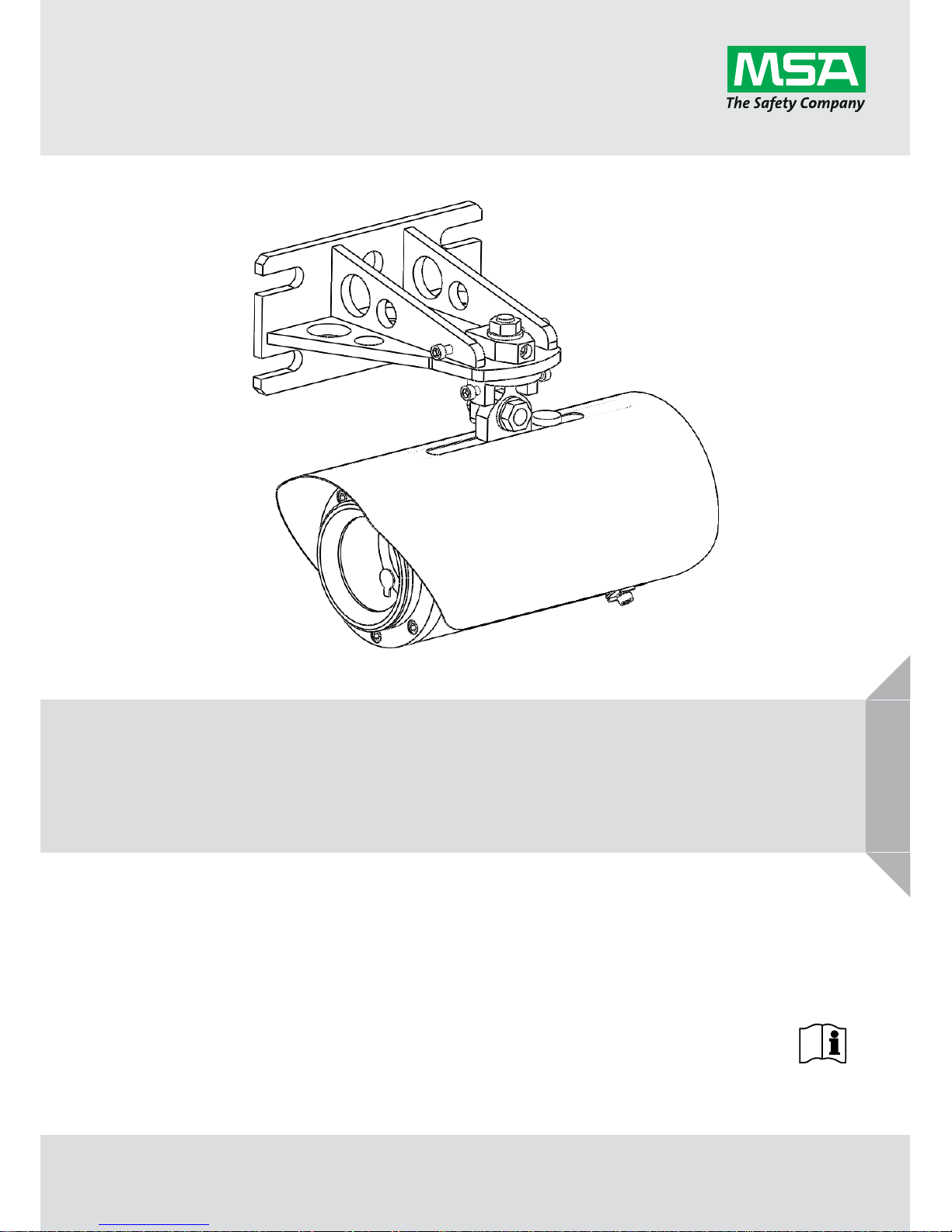
Senscient ELDS™ 1000 / 2000 Series
Open Path & Cross Duct Gas Detectors
A-5170-0 / Rev 15
Page 2
Schlüsselstrasse 12
8645 Rapperswil-Jona
Switzerland
Manufacturer:
Senscient Ltd.
Units F1-F4 Arena Business Centre
Holyrood Close
Poole
Dorset
BH17 7FP
United Kingdom
© MSA 2017. All rights reserved
Read and understand this Instruction Manual before installing, operating or servicing
ELDS 1000 / 2000 Series OPGD systems.
Page 3
Safety
Senscient ELDS™
Rev 15
3
GB
Safety
Ensure that you read and understand these instructions BEFORE operating the equipment.
Please pay particular attention to the safety Warnings / Special Conditions of Safe Use.
Warnings / Special Conditions of Safe Use
WARNING
1. The Senscient ELDS™ 1000 / 2000 Series gas detectors are Baseefa ATEX certified for use
in Hazardous (Explosive) Atmospheres; and CSA(UL) certified for use in Hazardous
(Classified) Locations/Zones.
2. For installations in Europe (ATEX Certified) install in accordance with IEC/EN60079-14.
3. For installations in North America and Canada install in accordance with ANSI/NFPA 70, the
Canadian Electrical Code C22.1 and the manufacturer’s instructions.
4. Elsewhere, the appropriate local or national regulations should be used.
5. ELDS™ 1000 / 2000 Series gas detectors must be properly earthed / grounded to protect
against electrical shock and minimise electrical interference. Internal and external
equipotential bonding facilities are provided for this purpose. For electrical installation design
considerations refer to section 3.3.
6. Operators must be fully aware of the action to be taken if the gas concentration exceeds an
alarm level.
7. ELDS 1000 / 2000 Series gas detectors do not contain any parts that can be replaced or
repaired by customers. If units require repair they must be safely removed from any
hazardous location / area in which they are installed, and returned to Senscient. Other than
the rear cover providing access to the terminals for connection purposes, the units are not
intended to be opened during operational service.
8. Test gases may be toxic and/or combustible. Refer to Material Safety Data Sheets for
appropriate warnings and handling procedures / precautions.
9. Do not drill holes in any housing as this will invalidate the explosion-proof protection.
10. In order to maintain electrical safety, units must not be operated in atmospheres with more
than 21% v/v oxygen.
11. Ensure that the bolts which secure the front flameproof enclosure are fully tightened. The
securing bolts are stainless steel M5 X 16mm socket head cap screws grade A4-70. To
ensure replacement suitability contact Senscient or their approved agent/distributor.
12. Do not open the enclosure in the presence of an explosive atmosphere. Keep cover tight
when energised
13. The apparatus is certified for use in Hazardous Areas at atmospheric pressures not
exceeding 1.1 bar (16 psi).
14. Install only in environments with ambient temperature ranges of -40°C to +60°C.
15. For Europe (ATEX), apparatus incorporates an integral threaded cable entry (M25 x 1.5).
Terminate cable only with a suitable equipment certified ATEX cable gland (not a
component). To maintain water and dust ingress protection seal threads with suitable nonhardening sealant as described in IEC/EN 60079-14.
Note: See control drawing for product specification allowing selection of cable glands.
Page 4
Safety
4
Senscient ELDS™
Rev 15
GB
WARNING
16. For US/Canada the apparatus incorporates an integral threaded conduit entry (3/4”-14TPI).
Install a conduit seal within 18 inches. In order to maintain ingress protection seal threads
with a suitable material e.g. a non-hardening thread sealant or PTFE tape etc. See control
drawing at the end of this manual.
17. For all installations use cable / conductors rated for service at temperatures ≥ 85°C
18. At all times during transit, installation and commissioning protect lens from accidental direct
mechanical impact. Use Senscient OEM supplied packaging during transit.
19. The Transmitter and Receiver units must be mounted horizontally and protected from impact
i.e. do not mount at floor level or in areas where moving vehicles, personnel or loads may be
of concern regarding impact.
CAUTION
1. Use only approved parts and accessories with the Senscient ELDS™ 1000 / 2000 Series
gas detectors.
2. To maintain safety standards, commissioning and regular maintenance of
ELDS™ 1000 / 2000 Series gas detectors should be performed by qualified personnel.
3. Transit cases for the alignment telescope and gassing cell are manufactured from nonantistatic materials, and may, under certain circumstances become an electrostatic risk. It is
the user’s responsibility to take adequate precautions during transportation and use if taken
into hazardous areas.
Important Notices
1. Senscient Inc. can take no responsibility for installation and/or use of its equipment if this is
not done in accordance with the appropriate issue and/or amendment of the manual. The
purchaser should make Senscient aware of any External effects or Aggressive substances
that the equipment may be exposed to.
2. The user of this manual should ensure that it is appropriate in all details to the exact
equipment to be installed and/or operated. If in doubt, the user should contact Senscient Inc.
for advice.
3. Effect of explosive atmosphere on materials.
The Senscient ELDS™ 1000 / 2000 Series is manufactured from materials which exhibit good
resistance to corrosive substances and solvents. The Ex d enclosures are made from 316L
stainless steel and the explosion protected windows are made from robust and chemically
inert glass. Senscient are not aware of any significant effects of explosive atmospheres upon
these materials. The purchaser should make Senscient aware of any External effects or
Aggressive substances that the equipment may be exposed to.
4. The final and long term effectiveness of any Gas Detector depends heavily upon the user, who
must be responsible for its proper application, installation and regular maintenance.
Senscient Inc. reserves the right to change or revise the information supplied in this document
without notice and without obligation to notify any person or organisation of such revision or
change.
If further details are required that do not appear in this manual, contact Senscient or one of their
agents. Senscient will supply this manual in other languages of the European Union (countries
covered by the ATEX directive) upon request.
Page 5

Safety
Senscient ELDS™
Rev 15
5
GB
Help Us to Help You
Every effort has been made to ensure the accuracy in the contents of our documents. However,
Senscient can assume no responsibility for any errors or omissions in our documents or their
consequences.
Senscient would greatly appreciate being informed of any errors or omissions that may be found in
our documents. To this end we request that if you believe there are any errors or omissions,
please send us an e-mail at info@senscient.com describing the error or omission, so that we may
take the appropriate action.
Page 6

Contents
6
Senscient ELDS™
Rev 15
GB
Contents
1. Introduction.................................................................................................................................. 8
1.1. Information Notices ........................................................................................................... 10
2. System Description ................................................................................................................... 11
2.1. Introduction ....................................................................................................................... 11
2.2. Transmitter ........................................................................................................................ 12
2.3. Receiver ............................................................................................................................ 13
2.4. Adjustable Mounting Bracket ............................................................................................ 14
2.5. Sunshades ........................................................................................................................ 15
2.6. Cross Duct Mounting Plates ............................................................................................. 17
2.7. SITE Installation & Maintenance Software........................................................................ 19
3. Installation Design & Engineering ........................................................................................... 31
3.1. Introduction ....................................................................................................................... 31
3.2. Siting and Mounting .......................................................................................................... 32
3.3. Electrical Connections....................................................................................................... 44
4. Installation & Commissioning .................................................................................................. 56
4.1. Unpacking an ELDS 1000 / 2000 Series System ............................................................. 56
4.2. Installation Procedure ....................................................................................................... 59
4.3. Alignment .......................................................................................................................... 64
4.4. Cross Duct – Alignment Requirements ............................................................................. 79
4.5. Commissioning Using SITE .............................................................................................. 83
4.6. ELDS Bluetooth™ Wireless Connection ......................................................................... 103
4.7. Installation Checklist ....................................................................................................... 105
5. Functional Testing .................................................................................................................. 108
5.1. Introduction ..................................................................................................................... 108
5.2. SimuGas™ Auto ............................................................................................................. 111
5.3. SimuGas™ Live .............................................................................................................. 113
5.4. SimuGas™ Levels .......................................................................................................... 114
6. Maintenance ............................................................................................................................. 115
6.1. Scheduled Inspection, Cleaning & Testing ..................................................................... 115
6.2. Cleaning Lens-Windows ................................................................................................. 116
Page 7

Contents
Senscient ELDS™
Rev 15
7
GB
7. Problem Solving ...................................................................................................................... 118
7.1. The Commonest Problems, Issues or Misconceptions Affecting Successful Use of
ELDS OPGDs ................................................................................................................. 118
7.2. SITE Diagnostics Screen ................................................................................................ 120
7.3. Troubleshooting Tables................................................................................................... 125
7.4. Event Logs ...................................................................................................................... 129
8. Specifications .......................................................................................................................... 132
8.1. System ............................................................................................................................ 132
9. Certification.............................................................................................................................. 138
9.1. General............................................................................................................................ 138
10. Appendix A – Glossary ........................................................................................................... 143
10.1. Terminology .................................................................................................................... 143
10.2. Measurement Units ......................................................................................................... 143
10.3. Abbreviations .................................................................................................................. 144
11. Appendix B – Accessories & Spare Parts ............................................................................ 145
11.1. ELDS™ Accessories & Spare Parts ............................................................................... 145
12. Appendix C – Functional Testing Using Gas ....................................................................... 147
12.1. Introduction ..................................................................................................................... 147
12.2. Testing with the Gassing Cell ......................................................................................... 147
12.3. Testing Cross Duct ELDS Systems with the Refillable Gas Test Cell ............................ 153
13. Appendix D – Manufacturer’s EC Declarations .................................................................... 158
14. Appendix E – HART Communications .................................................................................. 161
14.1. Overview ......................................................................................................................... 161
14.2. Electrical Connections / Configuration ............................................................................ 161
14.3. Details of ELDS Data Available via HART ...................................................................... 164
15. Appendix F – MODBUS Communications ............................................................................ 168
16. Appendix G – Measurement Range Guidelines ................................................................... 172
17. Appendix H – 4-20mA Current Output Ranges .................................................................... 179
Page 8

Introduction
8
Senscient ELDS™
Rev 15
GB
1. Introduction
The Senscient ELDS™ 1000 / 2000 Series is a range of open path, flammable and / or toxic gas
detectors that is currently available in the following versions.
Senscient ELDS™ Series 1000 CH
4
- Methane Detector
Senscient ELDS™ Series 1000 Ethylene, HF, HCl, NH
3
or CO2 Detectors
Senscient ELDS™ Series 1000 XD – Cross Duct Methane Detector
Senscient ELDS™ Series 2000 H
2
S - Hydrogen Sulfide Detector
Senscient ELDS™ Series 2000 CH
4
+ H2S - Simultaneous Methane &
Hydrogen Sulfide Detector
The Senscient ELDS™ Series 1000 detector consists of a Transmitter unit that sends an infrared
laser beam to a separate Receiver unit that can be installed on a line-of-sight at a distance of up to
200m. The ELDS 1000 Series CH
4
detector can be located where there is a risk that a leak of
flammable methane gas may occur, to provide a rapid, early warning of such a hazard. The
ELDS™ 2000 variants are similar, except that there are two coinciding infrared laser beams, which
can either be used to detect two or more gases, or to detect a single, difficult gas with high
sensitivity (e.g. Hydrogen Sulfide).
All ELDS™ gas detectors operate on the principle of absorption of infrared laser light. Gases
absorb light at specific wavelengths depending on their molecular composition. Hydrocarbon
gases such as methane and propane absorb in the infrared region of the spectrum. If a cloud of
target gas is present, the specific wavelengths of the infrared laser light output by the ELDS™
Transmitter are absorbed by the gas, introducing Harmonic Fingerprints onto the signals reaching
the Receiver that are proportional to the amount of gas in the beam.
The Senscient ELDS™ Transmitter unit produces the precisely controlled infrared laser light
required to detect the target gases; whilst the Receiver unit contains an infrared detector and
advanced signal processing electronics which look for the Harmonic Fingerprint produced by the
presence of target gas in the beam-path. Each unit is housed in a robust 316L stainless steel
housing. The Receiver features two 4 - 20mA analogue outputs which are used to signal the
quantity of each target gas measured in the beam-path, for example 0-1LFL.m CH
4
and
0-250ppm.m H
2
S for the Series 2000 detector. These outputs provide a linear relationship with the
measured gas burden.
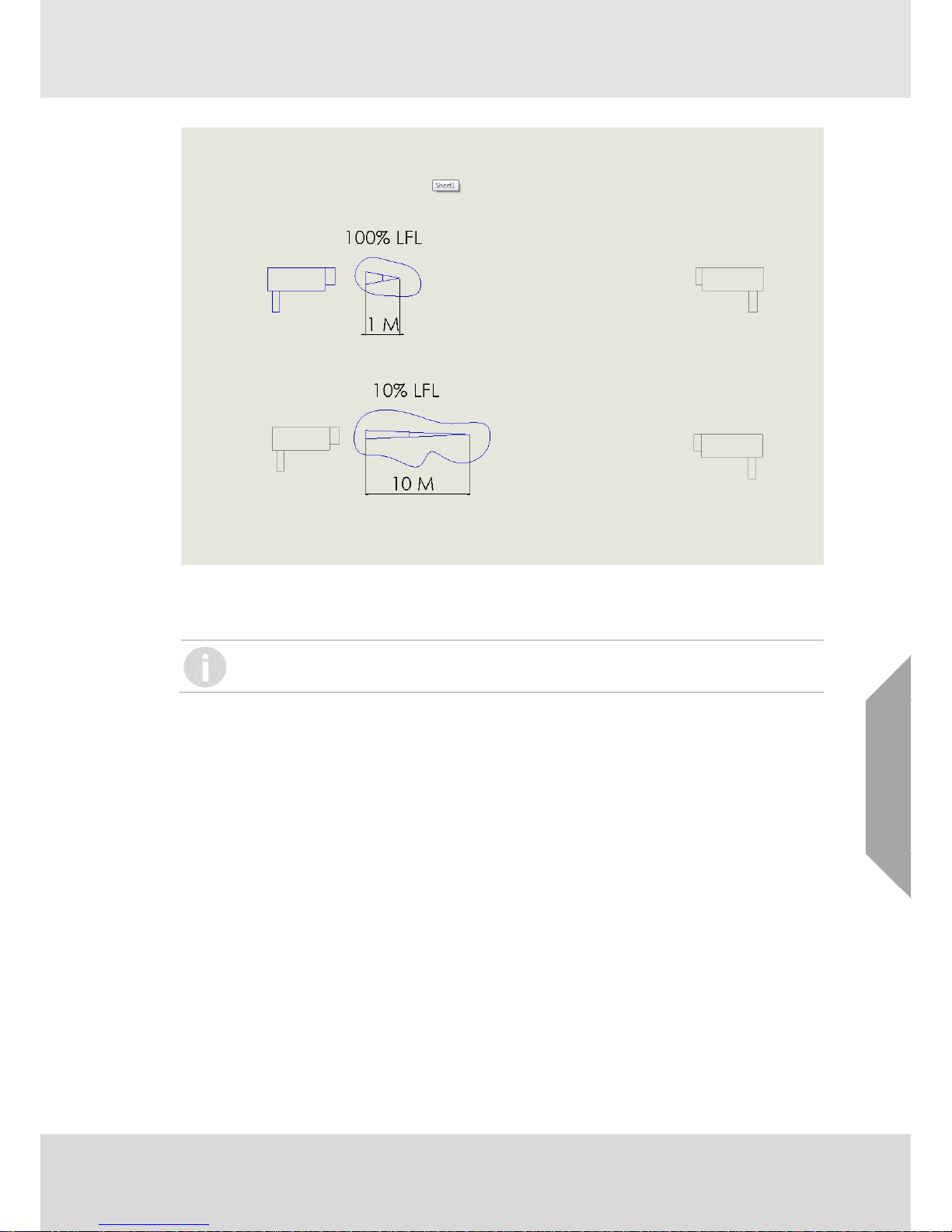
Note that open path detectors do not measure the point concentration of the target gas(es), rather
they measure the integrated concentration over the length of the measurement path between the
Transmitter and Receiver units. This means that the probable size of a gas cloud must be
considered when estimating the concentration of gas that might be present, with alarm levels
being set accordingly. The figures on the following page illustrate this.
Page 9
Introduction
Senscient ELDS™
Rev 15
9
GB
Each of these different gas clouds will produce the same ELDS reading of 1.0 LFL.m, however
only the 1
st
example where the gas cloud is very small actually has a potentially flammable
concentration within it.
THE TRANSMITTED LASER BEAM IS CLASS 1 (EYE-SAFE) PER IEC 60825.
Senscient ELDS™ is designed for use in the most demanding environments/applications and
provides a sensitive, fast and reliable response. The sophisticated ELDS™ open-path technology
provides immunity to sunlight and minimises the effects of environmental factors such as rain, fog,
ice, snow and condensation.
The Transmitter and Receiver units incorporate heated optics designed to minimise the build-up of
humidity, condensation, snow or ice on the glass lens-windows that could otherwise obscure the
optics in extreme conditions.
Both the Transmitter and the Receiver are microprocessor controlled with advanced selfdiagnostics and fault finding facilities.
Local communication between an operator/technician and the gas detector system is provided via
SITE (Senscient Installation & Test Environment) software running on an industrial computer,
using an RS485 or Bluetooth™ wireless communication link to either the Transmitter or Receiver.
SITE provides the user with a menu-style interface to select and invoke commands for
commissioning and configuring the system; and for viewing the system status and readings.
Page 10
Introduction
10
Senscient ELDS™
Rev 15
GB
1.1. Information Notices
The types of information notices used throughout this handbook are as follows:
WARNING
Indicates hazardous or unsafe practice which could result in severe injury or death to personnel.
CAUTION
Indicates hazardous or unsafe practice which could result in minor injury to personnel, or product
or property damage.
Provides useful/helpful/additional information.
If more information beyond the scope of this technical manual is required please contact
Senscient.
Page 11
System Description
Senscient ELDS™
Rev 15
11
GB
2. System Description
2.1. Introduction
Each Senscient ELDS™ 1000 / 2000 Series gas detector consists of two units, a Transmitter and
a Receiver. This separate Transmitter / Receiver configuration provides the most reliable basis for
open path gas detection. There are no transceiver units or retro-panels utilised in the Senscient
ELDS™.
There are several operating ranges of Senscient ELDS™ gas detector, e.g.:
Series 1000 CH
4
, 0 - 1000ppm.m, 0 - 1LFL.m 5 - 40m
40 - 120m
120 - 200m
Series 2000 CH4 0 - 1LFL.m + H2S 5 - 60m
Series 1000 XD CH4 0 - 10%LFL, 0 - 25%LFL, 0 100%LFL 0.5 - 5m
Series 1000 Ethylene 5 - 60m
40 - 120m
120 - 200m
Series 1000 HF 5 - 60m
60 - 120m
Series 1000 HCl 5 - 60m
Series 1000 NH3 5 - 40m
40 - 120m
Series 1000 CO2 5 - 40m
40 - 120m
Refer to Senscient for additional ranges and gases.
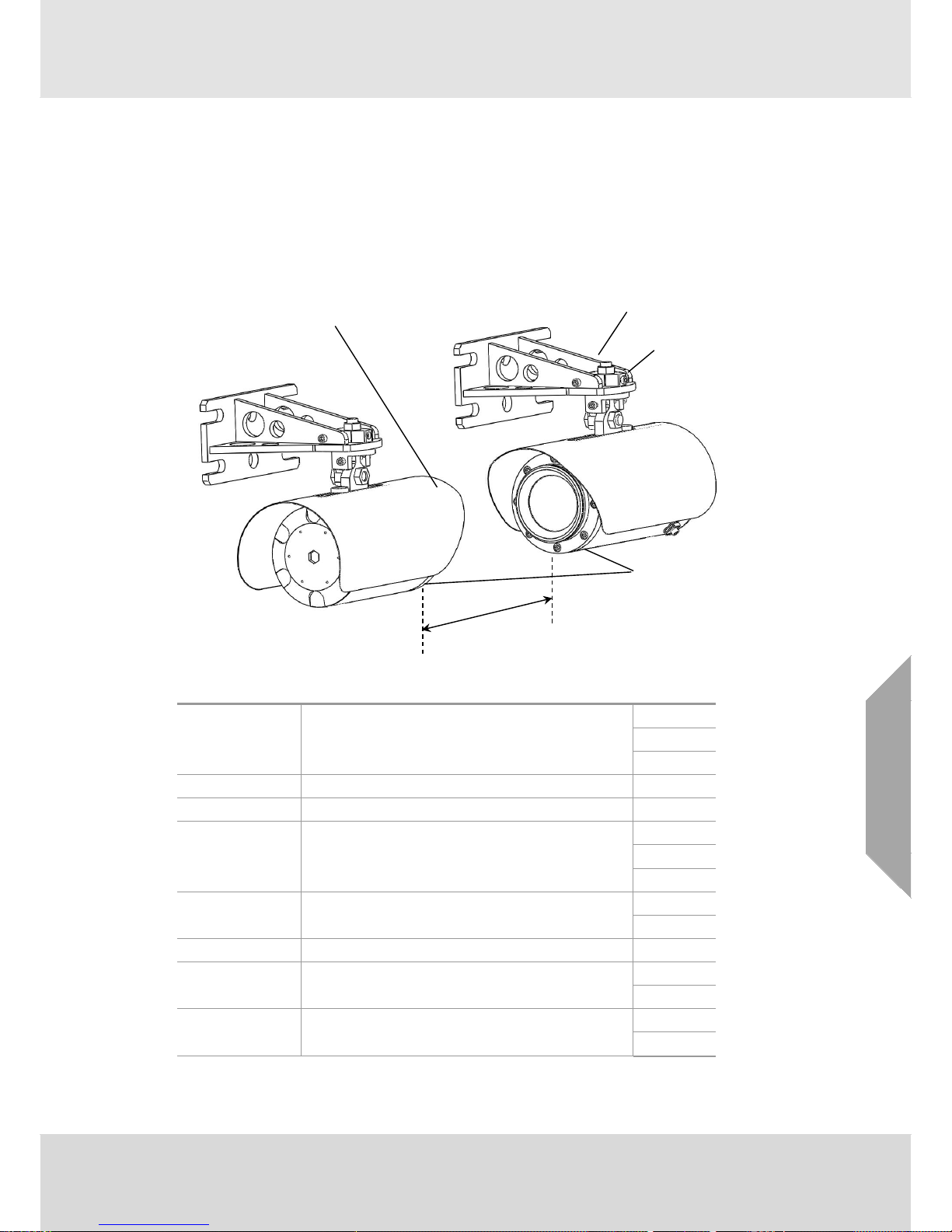
Sun Shade
Monitored Path
Tx and Rx Units
Alignment Adjustment
(horizontal and vertical)
Mounting Bracket
Page 12
System Description
12
Senscient ELDS™
Rev 15
GB
When designing an installation for Senscient ELDS™ 1000 / 2000 Series it is important
that the correct range of the gas detector for each path to be monitored is selected and
specified.
In order to avoid the problems associated with gas detectors being used beyond their
specified ranges or when incorrectly aligned, a procedure within the Senscient
Installation & Test Environment (SITE) checks for correct gas detector type, operating
range and signal levels before allowing an ELDS OPGD to be commissioned.
The Transmitter and Receiver are each mounted upon robust, adjustable mounting brackets. The
design of the mounting and alignment arrangement for the Senscient ELDS™ 1000 / 2000 Series
is highly accommodating, making it simpler to realise a good installation in a variety of locations
and environments. Installation details are given in section 3.
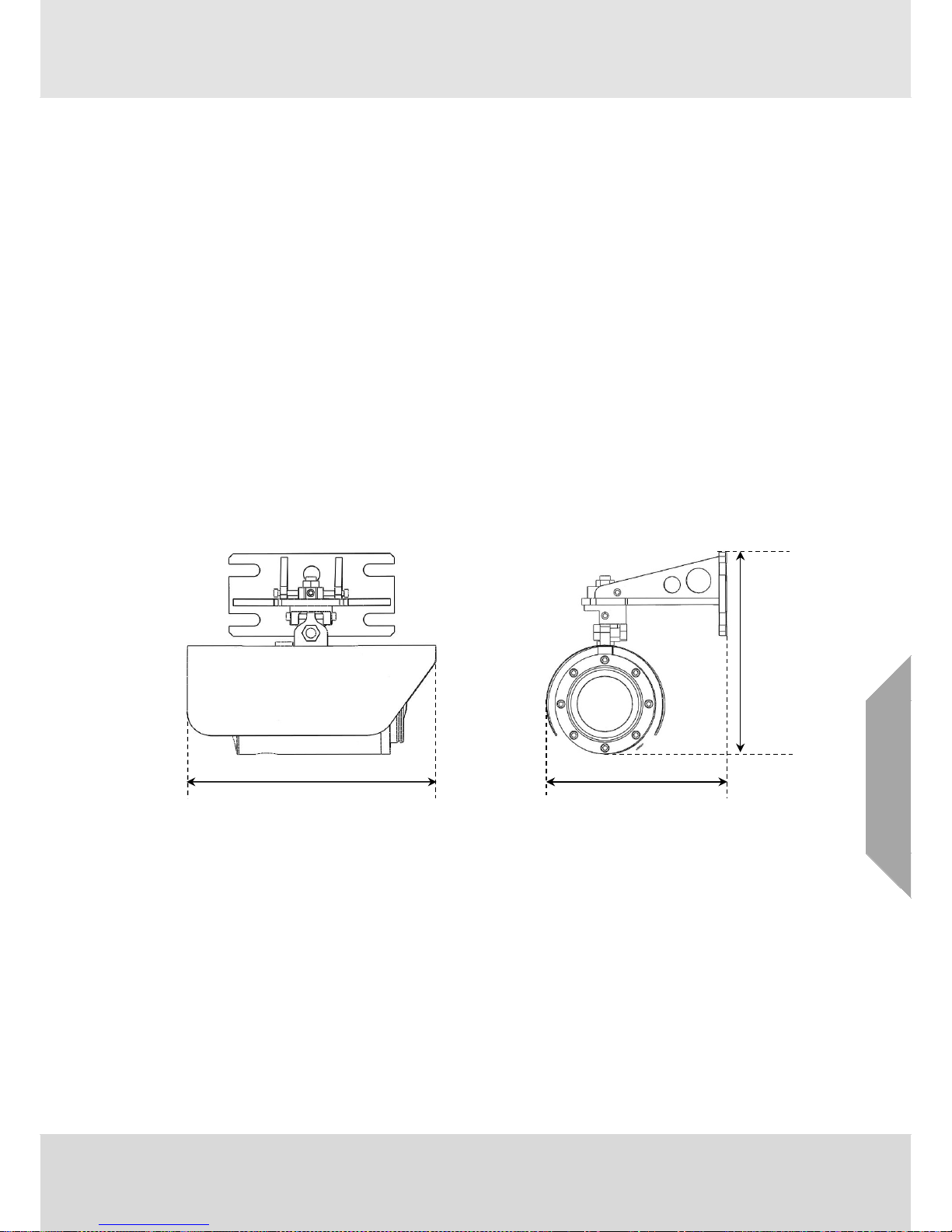
2.2. Transmitter
The Senscient ELDS™ Transmitter produces up to two controlled-divergence beams of infrared
laser light from solid-state laser diodes. The outputs from the laser diodes are partially collimated
using a faceted lens, the facets of which introduce the controlled-divergence that is necessary to
reduce system alignment sensitivity. The Transmitter operates continuously.
THE TRANSMITTED LASER BEAM IS CLASS 1 (EYE-SAFE) PER IEC 60825.
The Transmitter contains a small retained sample of the target gas(es) to be detected by the
system; and uses this retained sample as a reference to maintain its laser diode(s) in Harmonic
Fingerprint lock. By continuously maintaining Harmonic Fingerprint lock it is possible to be certain
that whenever target gas(es) enter the system’s beam-path this will introduce Harmonic
Fingerprints onto the laser signal(s), which will be seen and measured by the Receiver.
Maintaining Harmonic Fingerprint lock maintains detector calibration and ensures that SimuGas™
simulations faithfully simulate the presence of a pre-defined quantity of target gas(es) in the beampath. This is the basis of the SimuGas on-demand functional test technology incorporated in
Senscient’s ELDS OPGDs.
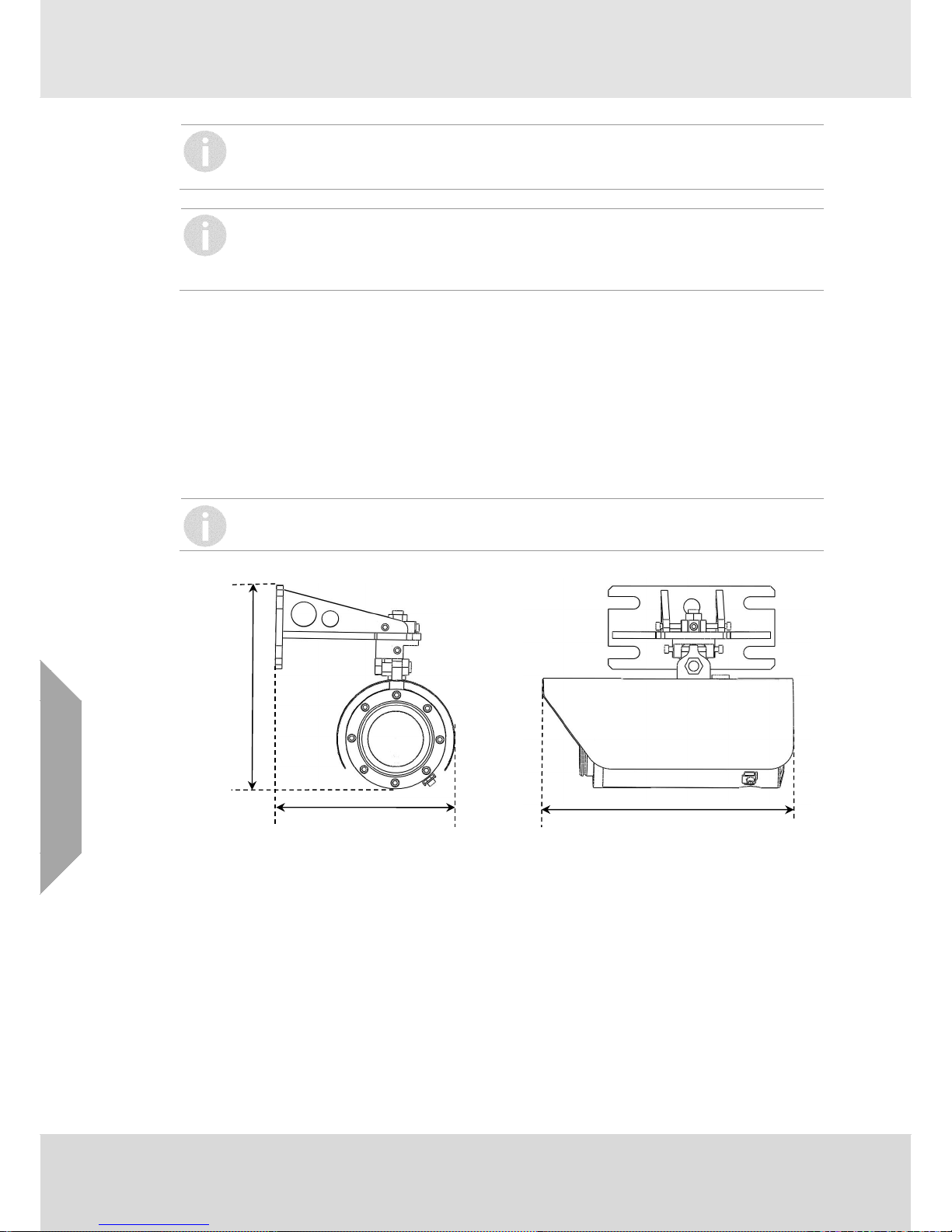
220mm
300mm
245mm
Page 13
System Description
Senscient ELDS™
Rev 15
13
GB
The Transmitter also incorporates links which can be used to communicate with an industrial
computer. Using SITE and these communication links, an industrial computer can be employed to
perform alignment checks, commissioning, configuration, functional testing, diagnostic procedures
and SimuGas™ tests.
The Transmitter window is heated to minimise condensation, frosting and the build-up of snow.
Three connections to the Transmitter are required, +24V, 0V and GND (for electrical safety).
2.3. Receiver
The Senscient ELDS™ Receiver collects infrared laser light from the Transmitter and determines
the size of any Harmonic Fingerprint components that have been introduced onto the beam(s) to
establish the quantity of any target gases present in the beam-path
The Receiver collects and concentrates infrared laser light from the Transmitter onto a single,
infrared detector using an aspheric, condensing lens-window. The detector output is amplified and
processed by a sophisticated electronic signal processing system which effectively removes any
ambient light and extracts Harmonic Fingerprint information related to the quantity of target gas in
the beam-path. The detector amplification chain incorporates an advanced Automatic Gain Control
(AGC) system that enables it to compensate for the wide range of signal levels that can be
received due to effects arising from rain, fog, snow, dirt etc. This enables the ELDS 1000 / 2000
Series to continue operating reliably in the harshest conditions that are likely to be encountered at
Oil & Gas installations around the world.
The solid state, InGaAs photodiode detectors used in the Senscient ELDS™ 1000 / 2000 Series
provide an exceptional dynamic range and superb temperature and long term stability. These
properties contribute significantly to the solar immunity and stability of the Senscient ELDS™
1000 / 2000 Series.
The primary output(s) of the Receiver are two 4-20mA loop outputs which can be configured for
source, sink or two-wire isolated operation. The outputs are factory calibrated to provide the
appropriate full scale range for the measured species and model variant. The output is typically
calibrated in units of LFL.m or ppm.m (see section 10.2 for the explanation of LFL.m and other
terms).
The Receiver also incorporates links which can be used to communicate with an industrial
computer. Using SITE and these communication links, an industrial computer can be employed to
perform alignment checks, commissioning, configuration, functional testing, diagnostic procedures
and SimuGas™ tests.
The Receiver window is heated to minimise condensation, frosting and the build-up of snow.
300mm
220mm
245mm
Page 14
System Description
14
Senscient ELDS™
Rev 15
GB
Between four and eight connections to the Receiver are required, depending upon the number and
configuration of the 4-20mA outputs used. These connections are required to provide +24V, 0V,
4-20mA(1), 4-20mA(2) and GND (for electrical safety).
The ELDS system does not have any gas alarm set functions. The 4-20mA signal outputs from the
Receiver are non-latching. If the ELDS system is intended to indicate a potentially flammable gas
concentration then any auxiliary equipment (e.g. control room plc, control unit or monitoring
apparatus etc.) shall have an alarm set point that is latching, requiring a deliberate action to reset.
If two or more set or alarm functions are provided the lower may be non-latching.
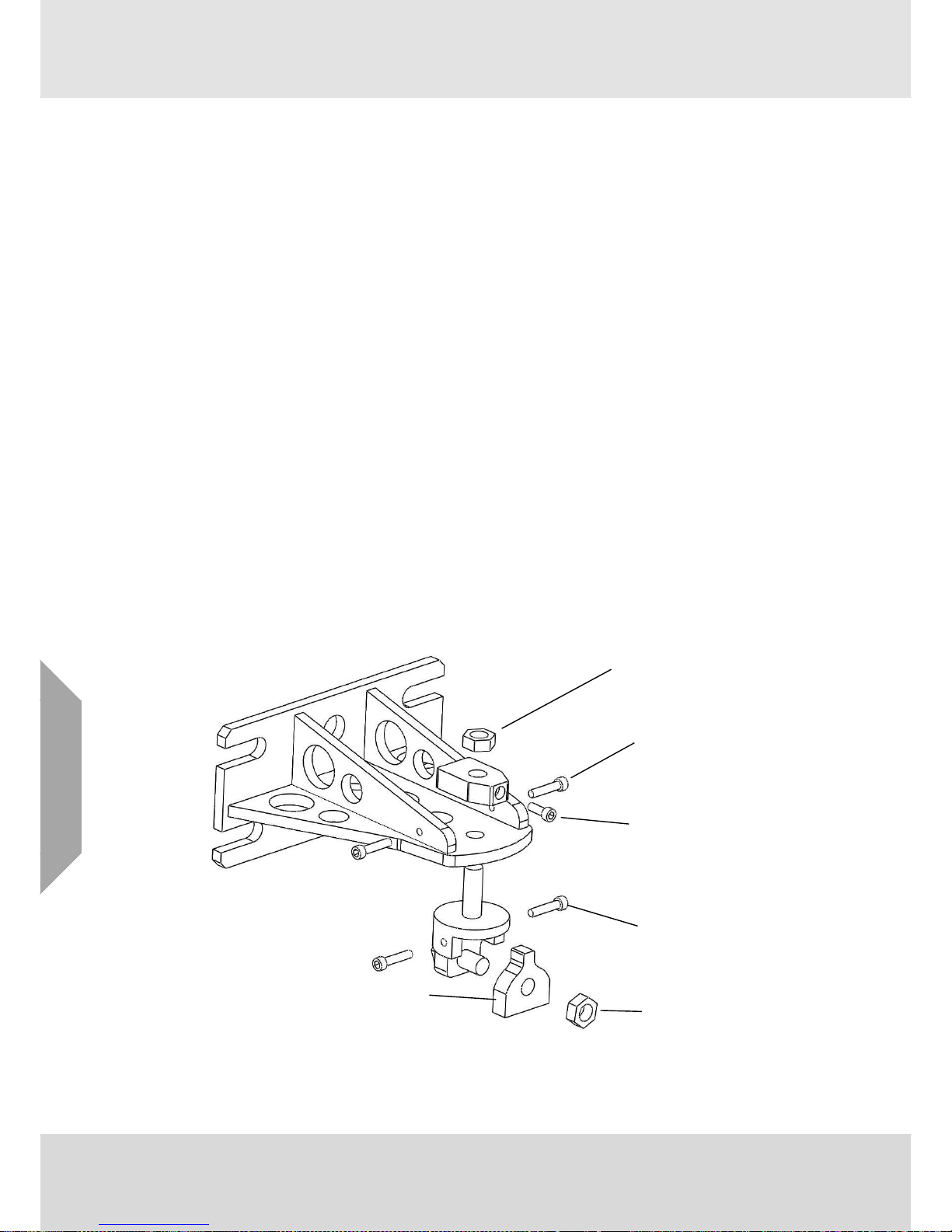
2.4. Adjustable Mounting Bracket
The adjustable mounting brackets for the ELDS 1000 / 2000 Series are:
Purpose-built for the Transmitter and Receiver.
Provide coarse and fine adjustment for quick, simple system alignment.
Rigid, stable and robust.
Made from 316L stainless steel.
The coarse horizontal adjustment facility enables a Transmitter or Receiver to be quickly pointed in
the approximate direction of its counterpart and provides a full 360º of rotation. The fine horizontal
adjustment facility enables a Transmitter or Receiver to be precisely aligned and locked-off with
respect to its counterpart, and has an adjustment range of ±25º.
The fine vertical adjustment facility enables a Transmitter or Receiver to be precisely aligned and
locked-off with respect to its counterpart and has an adjustment range of ±15º.
Alignment details are given in section 4.
Clamp nut
Mounting bracket
adjusting screw (2 off)
Adjustment clamp
lock screw
Pivot block adjusting
screw (2 off)
Clamp nut
Mounting Lug (on unit body)
Page 15
System Description
Senscient ELDS™
Rev 15
15
GB
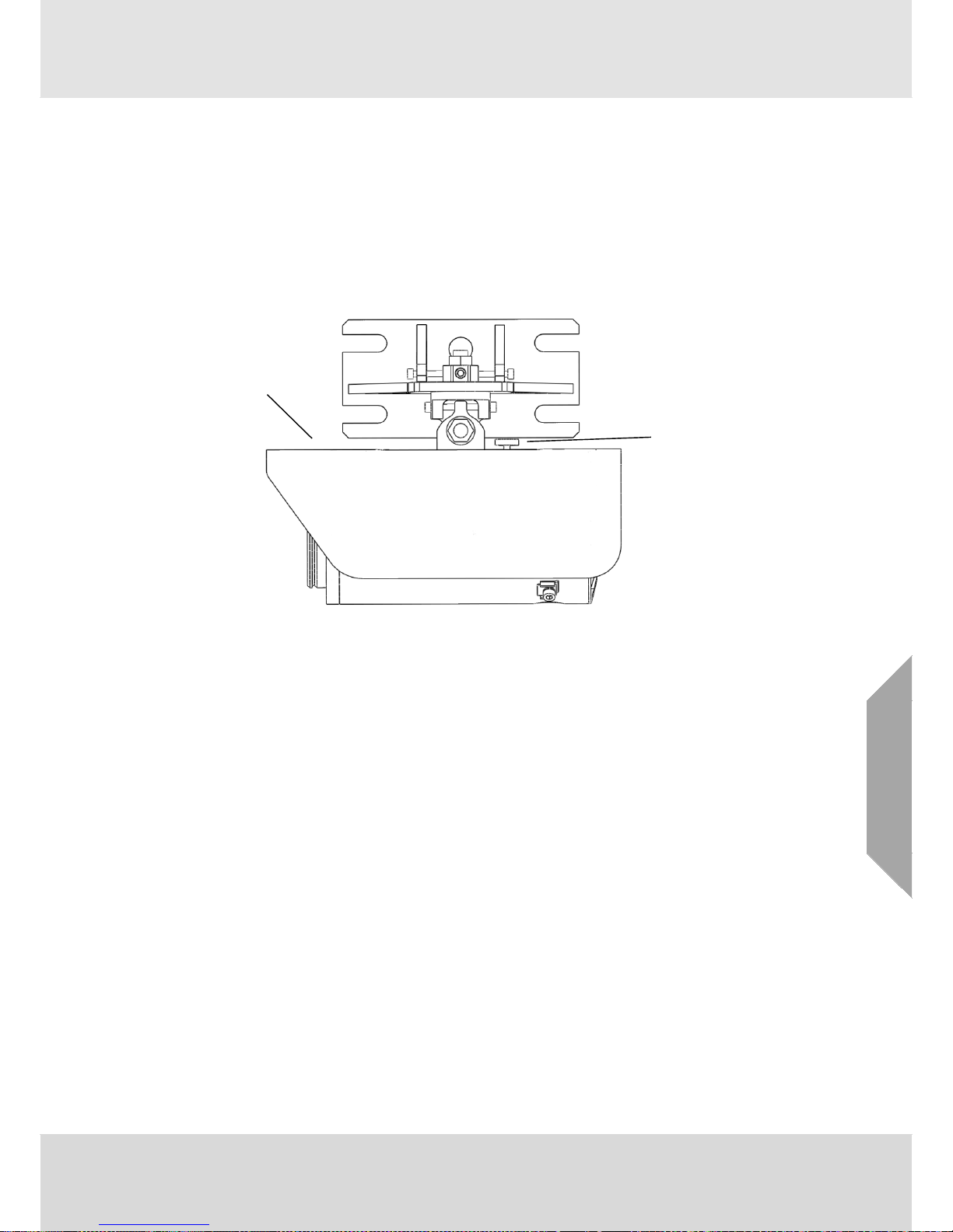
2.5. Sunshades
In order to provide Sun shading which is optimal for a wide range of operating climates, there are
two sunshades available for use with ELDS™ units.
2.5.1 Standard Sunshade
The standard sunshade is suitable for use in cold, temperate and moderately warm climates; and
is fitted along the mounting bar on the top of each ELDS™ unit. This sunshade’s position is
adjustable in order to facilitate use of the alignment telescope or provide easier access to the
electrical connections inside the terminal compartment.
The standard sunshade is fixed by a single retaining screw as illustrated. Loosen this in order to
allow adjustment of the position of the sunshade. Tighten the retaining screw to ensure that the
sunshade remains in the desired position.
Sunshade
Retaining Screw
Page 16
System Description
16
Senscient ELDS™
Rev 15
GB
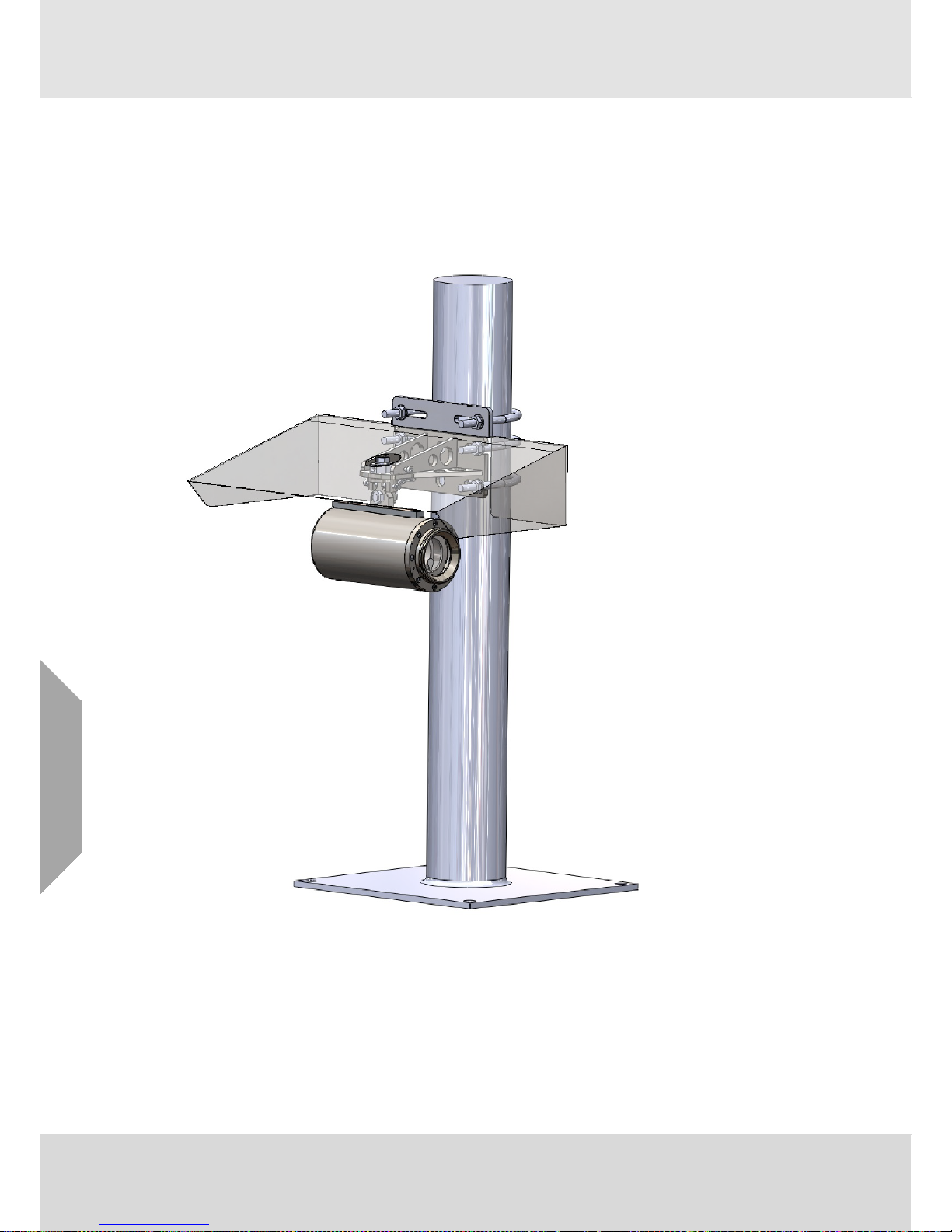
2.5.2 Enhanced Sunshade
The enhanced sunshade is designed for use in hot climates where intense, direct sunlight has the
potential to significantly increase the operating temperature of ELDS™ units unless greater
shading from solar radiation is provided. The enhanced sunshade is fitted above the mounting
bracket, attached to the same pole, wall or mounting structure that the mounting bracket is
attached to (see illustration below).
Depending upon the particular details of the installation, it may be necessary to temporarily
remove the enhanced sunshade in order to gain access to the terminal compartment or use the
alignment telescope. Make sure to re-fit the enhanced sunshade after completing any activities
that temporarily require its removal.
Page 17

System Description
Senscient ELDS™
Rev 15
17
GB
2.6. Cross Duct Mounting Plates
Cross Duct ELDS systems are designed to be mounted on the opposite sides of flat, parallelwalled ducts using one of three (3) available variants of Mounting Plate, or the standard Adjustable
Mounting Bracket (ELDS VZ unit only).
The installation designer’s attention is drawn to the fact that each Transmitter or Receiver
unit of a Cross Duct ELDS system weighs approximately 10kg, which may be sufficient to
cause unwanted bending of duct walls, especially if the duct walls are thin.
2.6.1 Standard Cross Duct Mounting Plate
The standard, 400mm x 400mm mounting plate substantially spreads the weight / load and
provides localised reinforcement of the duct wall; and is therefore recommended for use wherever
possible – and in particular on thin-walled ducts.
2.6.2 Small Cross Duct Mounting Plate
The small, 250mm x 250mm mounting plate is capable of being mounted on smaller ducts; but
consideration needs to be given as to how the weight / load will affect the duct wall when units are
so mounted. Local reinforcement / bracing of the duct wall may be required.
The installation Design Authority is responsible for ensuring that the method chosen for
mounting Cross Duct ELDS units on the intended duct is sufficiently rigid and stable.
Page 18
System Description
18
Senscient ELDS™
Rev 15
GB
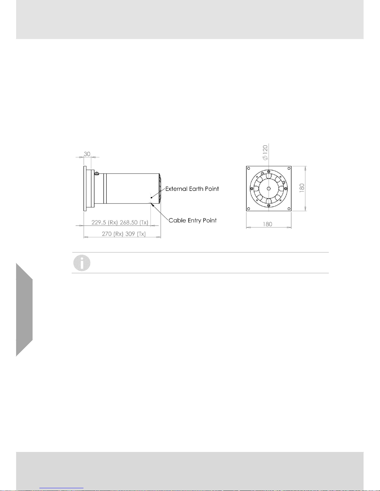
2.6.3 Retrofit Cross Duct Mounting Plate
The 180mm x 180mm retrofit mounting plate is capable of being mounted on the same mounting
holes as an earlier generation of Cross Duct unit supplied by another manufacturer. There is a
reasonable likelihood that mounting Cross Duct ELDS units on ducts using the retrofit mounting
plate will cause bending of the duct wall. Consequently, this method of mounting Cross Duct ELDS
units should only be considered for retrofit applications where it is impossible or impractical to
engineer a superior mounting arrangement. In such circumstances, the installation Design
Authority should also consider local reinforcement / bracing of the duct wall to reduce bending;
and / or the use of alignment adjustment bushings* to provide compensation for such bending.
NB: Customer / user should retain the original installation’s internal plates - to which this retrofit
mounting plate will be attached.
The installation Design Authority is responsible for ensuring that the method chosen for
mounting Cross Duct ELDS units on the intended duct is sufficiently rigid and stable.
* Alignment adjustment bushings are available from Senscient (Part Number A-5126-0) for use
with Cross Duct ELDS systems where the duct walls are highly out-of-parallel, or have bent under
load by an amount greater than the angular tolerance of the Cross Duct ELDS system. Provided
that the angular errors arising from these sources are less than ±5° (per side) and the duct wall
deformation is relatively stable, the alignment adjustment bushings should be capable of returning
the alignment of Cross Duct ELDS systems to within their operational angular tolerance.
(NB: Alignment adjustment of ELDS VZ units is made possible by use of the standard Adjustable
Mounting Bracket.)
Page 19
System Description
Senscient ELDS™
Rev 15
19
GB
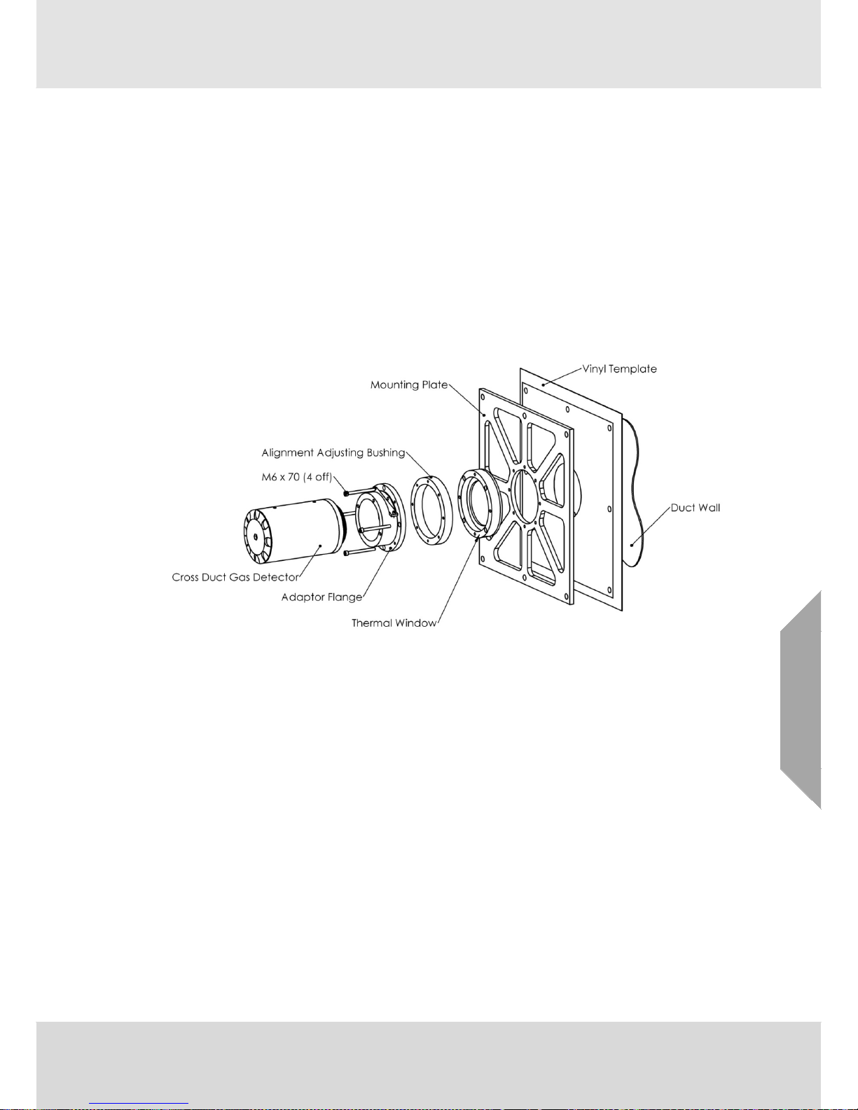
2.6.4 Thermal Window for Cross-Duct Units
In order to allow ELDS Cross Duct units to be mounted upon ducts which may temporarily reach
internal temperatures that are higher than the maximum upper service temperature for which
ELDS systems are certified (+60ºC), a mounting arrangement which includes a thermal window is
available. This arrangement insulates an ELDS unit’s lens-window from hot gases inside the duct,
allowing ELDS XD units to continue being used provided that air temperatures outside of the duct
are within the certified range.
Provided that there is adequate ventilation; and any in-duct temperature excursion is not of too
long a duration (≤ 15 minutes), it should be possible to mount and operate XD ELDS units on
ducts where air / gas temperatures inside the duct of up to 120ºC are temporarily present. Longer
term operation at high duct temperatures, or operation in conditions of restricted ventilation would
require measurement of the temperatures that the XD ELDS units become exposed to - in order to
ensure that the maximum certified operating temperature of +60ºC is not exceeded.
2.7. SITE Installation & Maintenance Software
SITE (Senscient Installation and Test Environment) is a software application provided by
Senscient to enable the installation, commissioning and testing of all types of ELDS OPGD
products; and is supplied pre-installed on ATEX or CSA (UL) certified industrial computers. Due to
the complexity of the computing and communications technologies employed by SITE, Senscient
can only provide support to users that are running SITE on factory tested and approved platforms.
SITE is capable of communicating with ELDS units either over RS485 or Bluetooth™ * wireless
communications links. The RS485 connection is made via a USB:RS485 adaptor included as part
of the installation kit. The Bluetooth™ connection is built into the industrial computer and is factory
activated and configured for use with SITE and ELDS units. More detailed information and
guidance with respect to the type of communication link to use when working with ELDS units is
provided in sections 4.5 to 4.7.
*All ELDS units can be commissioned using the RS485 communications link, regardless of their
type or age. From November 2011 onwards, Bluetooth™ communications were added alongside
RS485 with the introduction of Mod State 1, open-path, ELDS units. (The Mod State of ELDS units
can be found on the certification / serial number label on the terminal compartment cover.)
The necessary steps to commission a system using SITE are outlined in section 4.5 and some key
maintenance and problem solving guidance is provided in section 7.2. The following sections here
provide an overview of SITE itself.
Page 20
System Description
20
Senscient ELDS™
Rev 15
GB
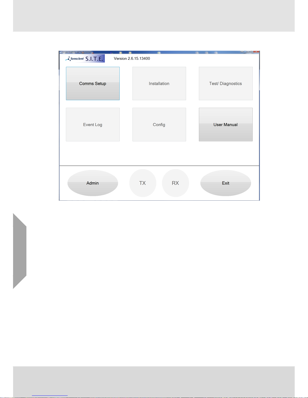
2.7.1 SITE Main Screen
The SITE screen is divided into two areas. At the top are a sequence of ‘buttons’ that are used to
access installation and maintenance facilities, to connect SITE to ELDS units and also to provide
access to this Technical Manual.
The area at the bottom provides access to various administration functions via the Admin button,
and also allows individual access to the Tx or Rx to be selected for operations initiated by the
Config, Event Log and Installation buttons.
An outline description of these functions is provided in the following sections, however more
detailed information is also provided in later sections of this document as individually detailed
below.
Note that the SITE version is presented at the top of the screen, 2.6.15.13400 in this example.
When SITE first starts this number is truncated to just the first 3 number groups (which is sufficient
to uniquely identify the SITE version), however clicking on the number will reveal the additional
group which defines the precise software build version as illustrated here.
Page 21

System Description
Senscient ELDS™
Rev 15
21
GB
2.7.2 Comms Setup
Selecting the Comms Setup button will open a separate dialogue as illustrated below which
facilitates connecting SITE to an ELDS Tx, Rx or both. Further details of this are provided in
section 4.5 as part of the commissioning instructions.
The majority of the functions available in SITE only become active once a connection to an ELDS
unit is made in this way. As illustrated above most of the buttons except Comms Setup,
User Manual and Admin are ‘greyed’ and unavailable until a connection is made.
The connection to an ELDS unit can be either via a wired (RS485) connector or via a Wireless RF
(Bluetooth) link, the appropriate option is initiated by selecting the required “radio button” selector.
The additional Modbus option is provided to allow units that are configured for Modbus operation
to be reverted back to ELDS communication over the RS485, this is necessary in order to utilise
any other facilities within SITE to maintain or inspect a unit via the RS485 link. Once connected via
the “MODBUS” option in this connection dialogue box it is possible ‘un-select’ Modbus operation in
the unit by navigating to the Config/Modbus page and clicking the option to disable Modbus.
Details of configuring Modbus are described in detail in section 2.7.6.
Once a connection is made then one of the indicators TX or RX at the bottom of the main SITE
screen will turn green and become slightly larger as illustrated here:
Page 22
System Description
22
Senscient ELDS™
Rev 15
GB
In this case both an ELDS Transmitter and Receiver has been connected, the ‘active’ connection
is to the Transmitter (the TX button is green and larger). To select the Receiver simply use the
mouse or touchpad to select (click on) the RX button which will then change to green and become
larger.
2.7.3 Installation
The installation button allows an ELDS Transmitter (see section 4.5.1 for more detail) or Receiver
(see section 4.5.2 for more detail) to be installed.
It is essential to install an ELDS Transmitter first when installing an ELDS system. This is
because essential calibration information must be copied from the Transmitter to the
Receiver, so SITE must access the appropriate Transmitter before any attempt is made to
install a particular Receiver. Once a Transmitter has been installed by SITE it will
remember the details of that unit and so it is not necessary to re-install the Transmitter if
the Receiver needs to be re-installed at a later date.
Select the appropriate unit to be installed (TX or RX) before selecting the Installation option.
2.7.4 Test/Diagnostics
The Test/Diagnostics button provides access to key information and test functions regarding the
connected ELDS unit(s). These functions are described in detail in section 7.2 with specific
information regarding the Receiver and Transmitter being in sections 7.2.1 and 7.2.2 respectively.
This option will provide information on either the Transmitter or Receiver or both depending
on which ELDS units are connected. If only one unit is connected then the whole of the
screen is filled with information regarding just that unit. If both a Transmitter and Receiver
then the screen will split vertically with the Receiver information on the left side and the
Transmitter on the right side.
2.7.5 Event Log
This button provides access to the internal ‘event’ log of the selected ELDS unit.
The ELDS unit selected for interrogation is determined by the TX or RX buttons at the
bottom of the SITE main screen. The larger (green) button identifies the unit that will be
examined.
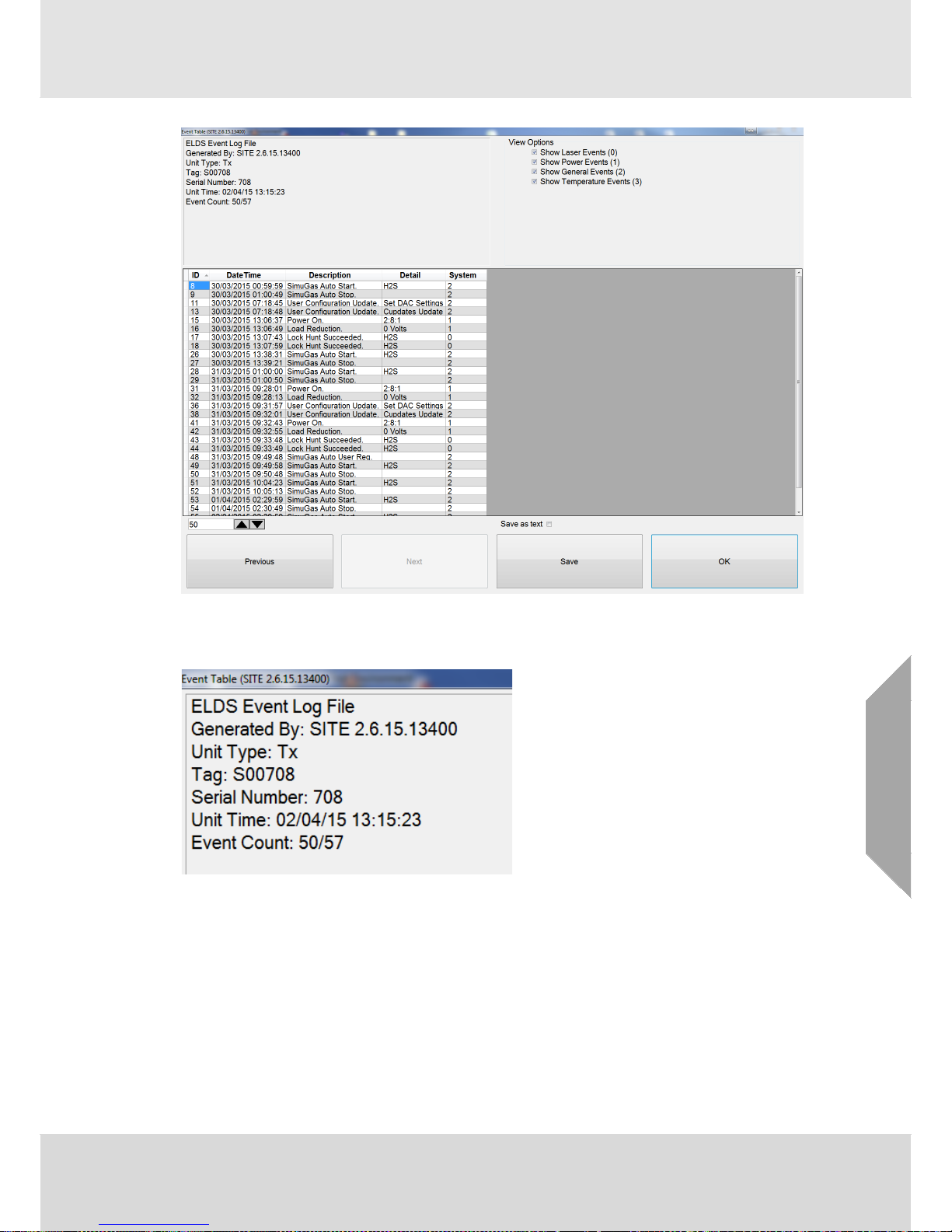
The following screen is presented and will normally be populated by the most recent 50 events
recorded in the ELDS unit selected.
Page 23
System Description
Senscient ELDS™
Rev 15
23
GB
The format and options of this event viewer screen are described in the following sections.
Header
The header information is presented in the top-left corner of the Events screen. Some key
information about the unit and SITE version is presented along with the time of the download
(based on the internal time in the ELDS unit) as well as an indication of the events selected. In this
example the display has selected (read) 50 events from the unit, however the total number of
events available is 57. Note that ELDS units can hold up to 186000 events, this is a rolling buffer
so once it becomes full the oldest events are discarded as new events are stored.
Page 24
System Description
24
Senscient ELDS™
Rev 15
GB
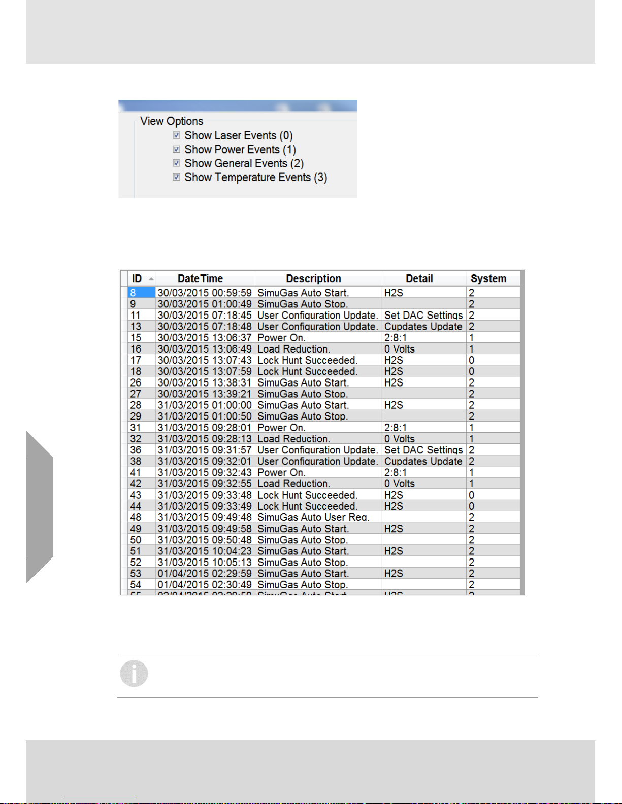
View Options
It is possible to filter the ‘class’ of events that are presented in the view by selecting/deselecting
the options in this area (top-right of the Events screen). By default all event classes are presented,
deselect the desired options to remove the associated events from the presentation.
Event List
The events are presented in the table area as illustrated here. Each event has an ID number which
is effectively an ‘index’ to the event number within the ELDS unit, a Date/Time field which indicates
the time that the event was created, a general Description field and for some events also a Detail
field. The System column refers to the event class (as is identified by the View Options above).
Some events within an ELDS unit relate to system processes and are not normally
displayed for users. These ‘housekeeping’ events have ID numbers associated
and explain
why the ID numbers may have ‘gaps’ as is the case in this example above.
Page 25
System Description
Senscient ELDS™
Rev 15
25
GB
It is possible to re-order the displayed events by clicking on the header of any of the columns. In
this example the events are ordered by ascending ID number (the default when the events are first
read). Pressing the ID column header will reverse this order, or pressing any of the other column
headers will order the events by the data in the appropriate column.
A detailed description of the events that may be displayed is presented in section 7.4 below.
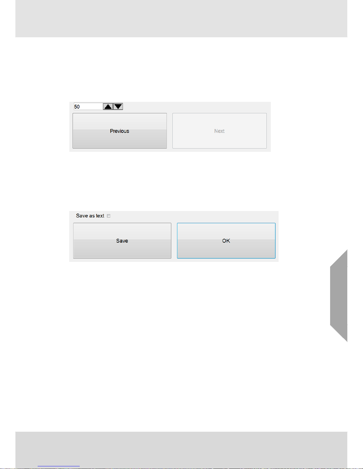
Read Options
SITE will initially read the last 50 events from the connected unit, however it is possible to
select/read further events if required by using the Previous or Next buttons at the bottom left of the
Events screen. Each press of these buttons will read the selected number of additional events
from the unit (determined by the numeric selection box).
If further events are not available then the appropriate button will be greyed and unavailable.
Output Options
The contents of the Event display can be output / saved to allow them to be incorporated into other
PC applications or to be supplied back to Senscient.
Pressing the Save button (bottom right of the Events screen) will output the data in an ‘internal’
format that can be used by Senscient to examine the event data in full detail. This is the preferred
format for supply of individual event information to Senscient (but note that Senscient generally
recommends supplying full ‘snapshots’ rather than just the events, see section 2.7.8).
Alternatively, if the “Save as text” checkbox is selected then the data is output as text format in a
“comma separate variable” (*.csv) file. Selecting this format is most useful if users wish to import
the event data into a spreadsheet for presentation or analysis.
Once the Save button is pressed a standard Windows File dialogue box is presented that allows
the user to select the location and name of the file that will be written.
Page 26
System Description
26
Senscient ELDS™
Rev 15
GB
2.7.6 Config
This button provides access to configuration information and to processes that allow the
configuration to be changed once a unit has been installed.
A new screen is presented with a range of options as illustrated below:
The screen is arranged with several ‘tabs’ or pages of information and in addition up to 3 context
sensitive buttons at the bottom. The ‘tabs’ displayed will depend on the unit (Tx or Rx) and also on
the connection type. The example here is for a Receiver. A Transmitter will not include the
“Zero Unit”, or “4-20mA Configuration” options but will include a “SimuGas” option.
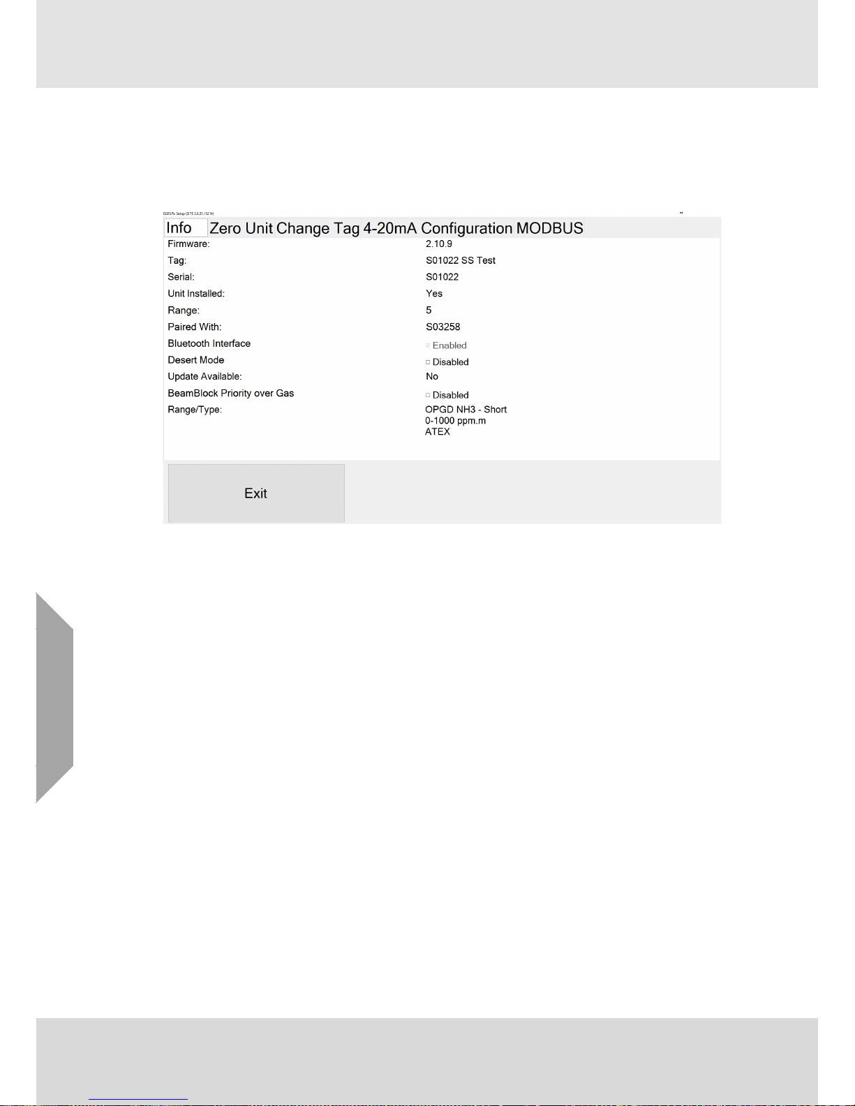
Info
This tab contains key information regarding the unit including the unit identity, firmware release
and configuration. In addition it provides access to three configurable items relating to Bluetooth
access, the control of the window heaters on the unit and the behaviour of Beam-Block in the
presence of gas.
Bluetooth Enabled/Disabled indicates if Bluetooth communication is currently facilitated on the
unit. By default all ELDS units are shipped with Bluetooth communication active, however some
customers may choose to inhibit this communication protocol for security reasons. The Bluetooth
support can be disabled or enabled as appropriate by checking the associated checkbox. In the
example above the Bluetooth is currently active so unchecking this checkbox will immediately
disable the Bluetooth connectivity in the unit. Note that access to this feature is restricted by
password access (see section 2.7.8 below). More details of how to disable Bluetooth are provided
in section 4.5.3 below.
Desert Mode is a feature to allow the control of the window-heaters on the ELDS unit to be
changed such that they are likely to be ‘off’ for a majority of the time in hot environments. This will
ensure that the power consumption and internal temperature of the ELDS unit will be minimised
and ensure the longest possible life of the internal components. It is recommended that the
“Desert” feature be enabled on units deployed in hot environments where daytime temperature is
likely to routinely exceed 25°C.
Page 27
System Description
Senscient ELDS™
Rev 15
27
GB
Beamblock Priority over Gas controls how the unit responds when the beam is blocked in the
presence of gas. Normally, ELDS units signal an error current (2.5mA by default) to indicate that
the beam is blocked. In the presence of gas, however, this behaviour is changed such that the last
gas value detected is maintained on the 4-20mA outputs whenever a beam-block occurs.
Optionally users can change this behaviour (for firmware versions 002.010.009 or later) such that
the ELDS does not ‘latch’ the last gas level but rather will signal the Beam-Block current even if
gas was being reported when the obstruction occurs.
Zero Unit
Units are normally ‘zeroed’ during installation; however it is also possible to repeat the zero
process at any time. This is recommended if a unit is physically disturbed (for example if the
alignment is inadvertently changed) or if units exhibit fingerprint or bad zero errors.
Change Tag
The unit ‘tag’ is normally assigned during installation but may be amended at any subsequent time
as required.
4-20mA Configuration
This tab provides information on the range of ‘fault’ conditions that apply to the unit and which will
be signalled over the 4-20mA current loop. A description of the configuration of this is provided in
section 4.5.2, item 8 therein. This tab provides repeat access to this facility should the original
arrangement require adjustment at a later time.
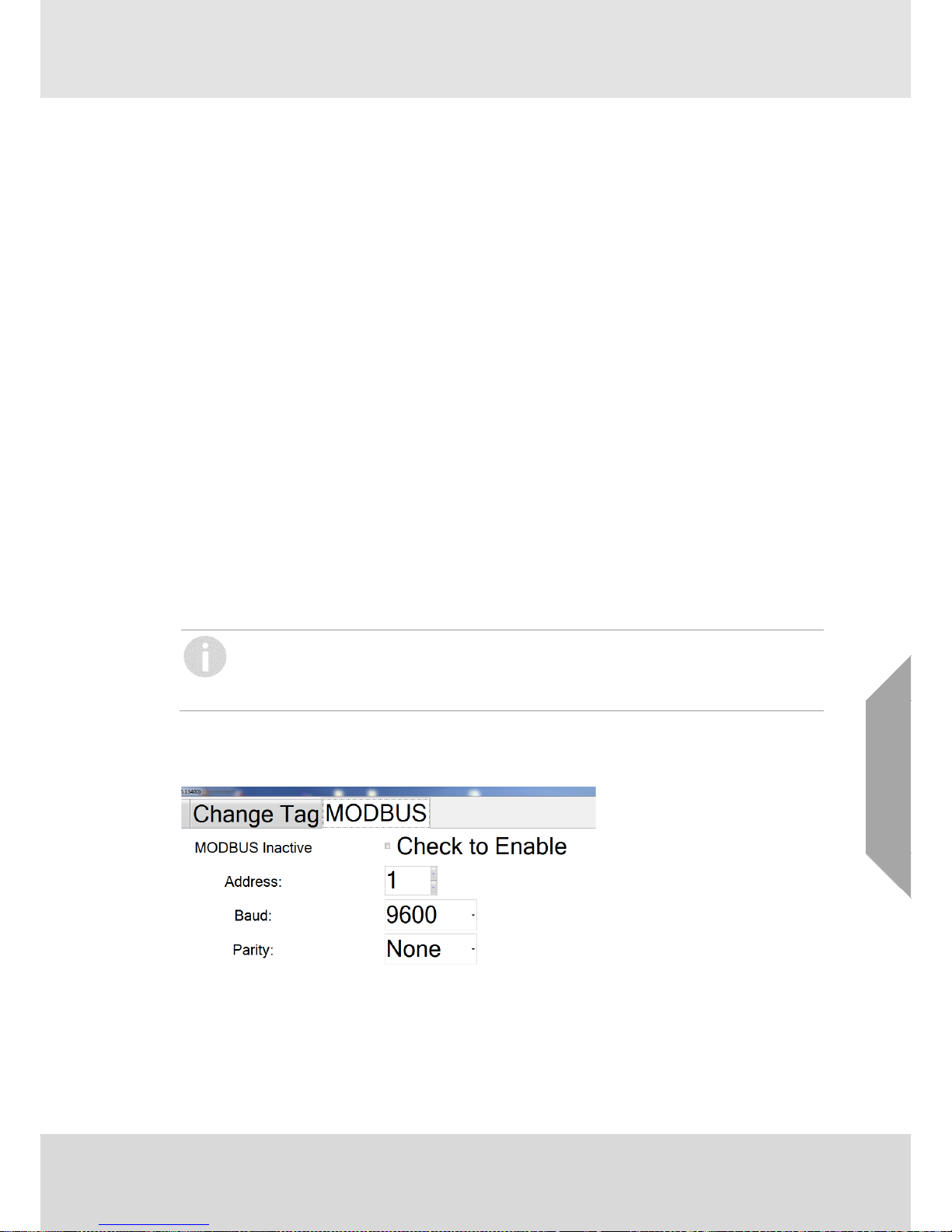
MODBUS
MODBUS support is available from all current ELDS units and is also historically supported for
most units. Units are not shipped with MODBUS support active and this tab provides a mechanism
to allow MODBUS to be configured and activated as required.
MODBUS shares the RS485 communication link, once MODBUS is activated then normal
interaction with the unit using SITE can only be undertaken using the Bluetooth link.
Ensure that Bluetooth communication is available with a unit prior to activating MODBUS
as without it further modifications or inspection of the unit with SITE will not be possible.
MODBUS can be activated through either a Bluetooth connection or via an RS485 link, however
Senscient recommend the use of a Bluetooth link when activating MODBUS. The following options
are presented on the MODBUS screen.
The Address must be assigned as required and must be in the range 1 to 247. This is a unique
value that identifies the unit on the MODBUS link.
Baud defines the communication speed that will apply, the default setting is normally 9600
however other rates are supported and can be selected as required.
Page 28
System Description
28
Senscient ELDS™
Rev 15
GB
Parity defines the parity checking that will be applied to the link. The default is ‘none’ but other
options are available as required from the drop-down list.
Once the required settings are selected check the “Check to Enable” option and then press the OK
button at the bottom right of the dialogue. This will write the changes to the ELDS unit and enable
the interface.
If this change is made via the RS485 link then SITE will not be able to communicate further
with the unit and will disconnect. This process may take a short while to complete in this
case.
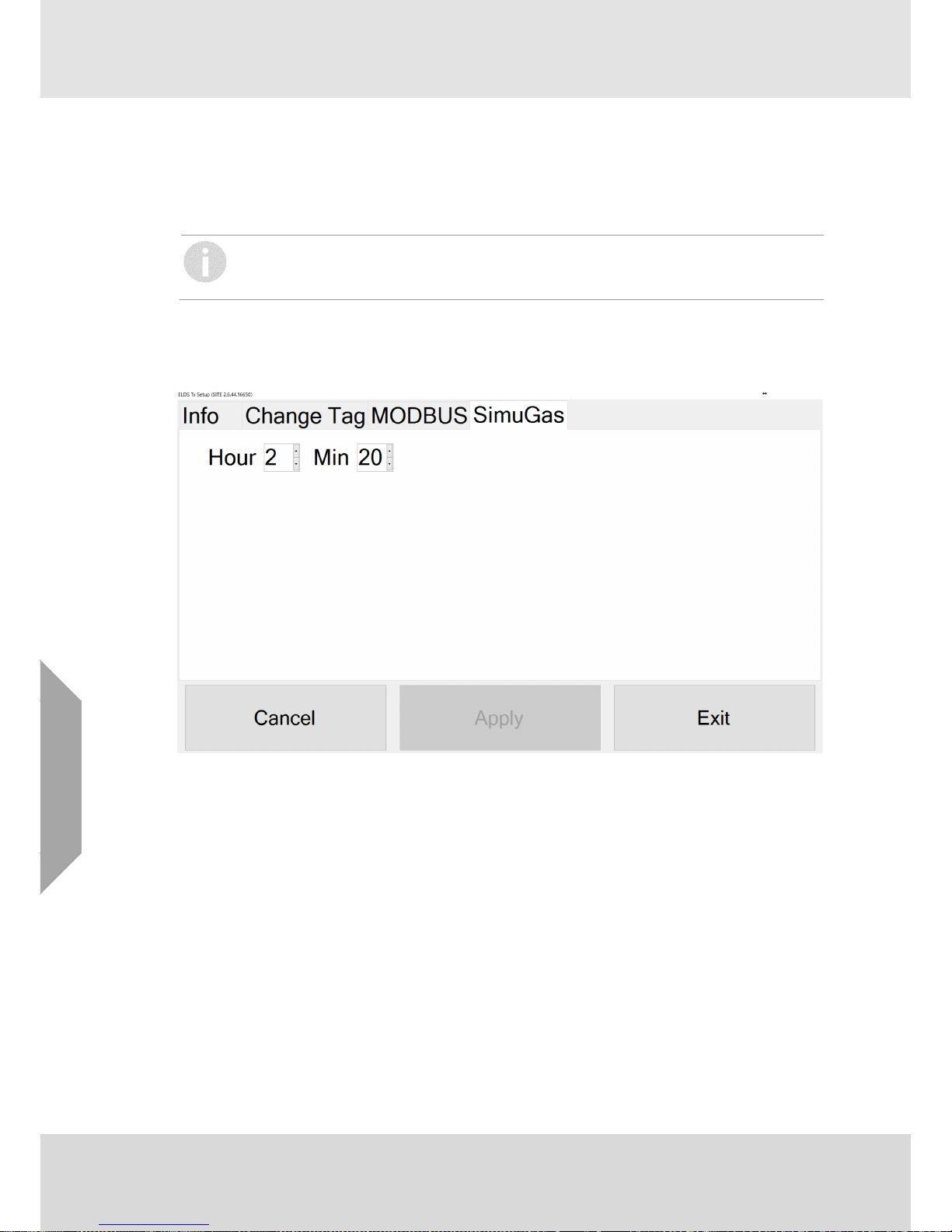
SimuGas
This tab is provided on Tx units and allows the user to examine and change the time of day that
the automatic SimuGas process will occur.
For older ELDS units the SimuGas time can be selected over the range Midnight (0 hours, 0
minutes) to 03:00 am (3 hours, 0 minutes). Units with firmware versions 002.010.018 or later will
support SimuGas at any time of the day. The time can be specified in 10 minute increments. When
any change is made the “Apply“ button will become enabled and will write the required changes to
the unit if clicked.
For older firmware version it is also the case that the revised SimuGas time will not apply until the
pending SimuGas occurs, for such versions SITE will provide a warning following “Applying“ the
change and offer the user the opportunity to re-start the Tx (which will then correctly establish the
revised SimuGas time). For later firmware versions this step is not necessary and will not be
presented.
2.7.7 User Manual
This provides a convenient link to this manual.
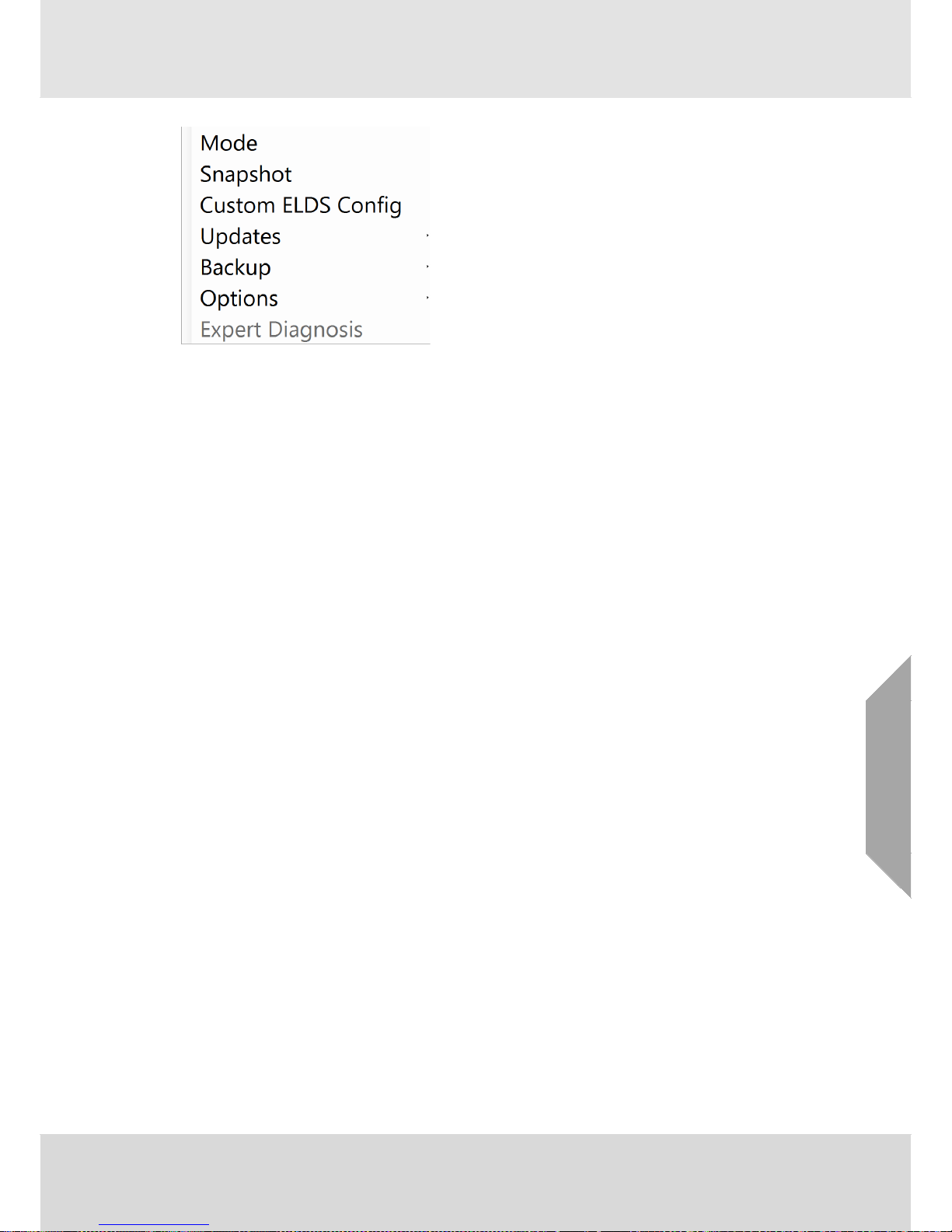
2.7.8 Admin
This provides a range of ‘administration’ items as illustrated below:
Page 29
System Description
Senscient ELDS™
Rev 15
29
GB
Mode
This provides access to a ‘log in’ screen and allows Senscient personnel or approved users to
access more advanced features of SITE. Appropriate passwords to access these features are
provided by Senscient; Senscient will normally require that users have additional training regarding
the additional features provided.
Snapshot
This will instruct SITE to download a complete ‘picture’ of the connected unit. This ‘snapshot’ may
take up to 2 minutes to acquire and will be automatically uploaded to the Senscient ‘service’ server
if an internet connection is available. In addition the snapshot is stored on the PC running SITE
and may be copied from there. The snapshot will be located in the following location within
“My Documents”
\Senscient\SITE\Log\nnnn
Here nnnn represents the unit serial number of the ELDS unit, for example S01234. Note that the
physical location of “My Documents” varies depending on the version of Windows being used on
the PC. Generally users should find a link to the appropriate place located in the “Start” button or
on their desktop.
Page 30

System Description
30
Senscient ELDS™
Rev 15
GB
Custom ELDS Config
This provides a direct access to the facility to adjust or configure the 4-20mA loop fault currents
and behaviours (see section 2.7.6 above and also section 4.5.2 item 8 below).
Updates
This provides access to SITE updates. It also can provide access to firmware updates but this
facility is limited to authorized users and is not described in further detail here.
If a “SITE update” is available then this sub-item will be accessible and selecting it will
automatically update the copy of SITE on the PC. Note that this process does take a few minutes
to complete. All these options are dependent on internet access.
Senscient recommends that users keep their SITE version updated by periodically checking this
option and updating when new versions of SITE become available. New versions generally
provide enhanced/improved features and in addition may correct issues that might arise.
Backup
This provides the option to create a ‘zip’ backup of the current SITE installation information. This is
located in the following location within “My Documents”
\Senscient\SITE\SBU
and takes the form of a ‘zipped’ folder which contains a record of the units that have been installed
by SITE on the PC.
There is also an option to ‘Purge’ the current configuration. These options are provided to facilitate
some advanced trouble-shooting options for Senscient engineers and are not intended for
customer use.
Options
Contact Us, provides a convenient link to Senscient support through the email client on the PC
running SITE.
Auto Install, provides a means to enable an advanced feature of ELDS which is not currently
activated. This is a ‘place holder’ for future enhancements involving more flexible installation
options.
Remote Assistance is an advanced feature that may be utilised by authorized users or Senscient
engineers.
Expert Diagnosis
This is an advanced feature provided for use by Senscient Engineers. This option is not available
to normal users of SITE.
Page 31

Installation Design & Engineering
Senscient ELDS™
Rev 15
31
GB
3. Installation Design & Engineering
3.1. Introduction
WARNING
The applicable National Code of Practice regarding selection, installation and maintenance of
electrical apparatus for use in Hazardous Areas / Hazardous (Classified) Locations / Zones must
be complied with at all times.
The Senscient ELDS™ 1000 / 2000 Series has been designed, engineered and field-tested to be
the most robust, reliable Open-Path Gas Detector (OPGD) available. The design and ELDS™
technology employed in the Senscient ELDS™ 1000 / 2000 Series make it far more resistant to
the adverse effects of the operating environment and non-ideal installations than previous
generations of OPGDs.
With careful consideration of the intended operating environment and the installation design, the
installer/operator can maximise the reliability, availability and performance achieved with ELDS™
OPGDs.
Before designing or specifying an installation for Senscient ELDS™, it is strongly recommended
that the installation design authority reads and understands this chapter, and considers how the
information and recommendations provided can be applied to their installation(s).
If a design authority has any queries concerning their installation design, they should contact
Senscient or their local agents.
Senscient is committed to ensuring that customers achieve reliable operation of their Senscient
ELDS™ OPGDs. For this reason, Senscient ELDS™ OPGDs should only be installed by fully
trained personnel (trained by Senscient or a Senscient authorised trainer). This training will
provide the installer with a clear understanding of the Senscient ELDS™ OPGD product and the
associated accessories and tools. It will also provide familiarity with the installation, alignment and
commissioning procedures, plus installation assessment skills to identify any potential problem
areas.
For each installation, it is recommended that the installer should check the installation and
operating environment against the Check List presented in section 4.7.
The transmitted laser beam is Class 1 (eye-safe) per IEC 60825.
Page 32

Installation Design & Engineering
32
Senscient ELDS™
Rev 15
GB
3.2. Siting and Mounting
3.2.1 General
When designing an installation for a Senscient ELDS™ OPGD it is important to give consideration
to where it is to be located with respect to gas leak hazards, what potential sources of problems
may be encountered in this location; and how the unit is to be mounted and supported.
3.2.2 Location for Best Coverage
Guidance on the positioning of gas detectors to provide the best detection coverage is contained
in national Codes of Practice. It is recommended that the installation designer consults these
Codes of Practice. Senscient would advise that the best current methodology for siting all types of
fixed gas detectors is based upon the expert use of gas dispersion modelling, performed for the
particular area(s) of plant or facility where potential gas leak hazards exist. There are a number of
organisations with the gas dispersion modelling tools and expertise necessary to perform this
work. In general, for OPGDs the following positions usually provide the best results:
Running parallel to the physical perimeter of an area of plant or facility containing potential gas
leak hazards.
Forming a continuous ‘ring-fence’ surrounding an area of plant or facility containing potential
gas leak hazards.
At sufficient distance from any potential leak sources for dispersion to produce a gas cloud of a
size that will reliably be intercepted by the beam-paths of the OPGDs employed.
Between potential leak sources and any known or likely sources of ignition.
For natural gas: beam-path parallel to the ground / floor and above the height of most of the
valves and flanges in the vicinity.
For toxic gases: beam-path parallel to the ground / floor at ‘breathing height’ (~ 1.4m - 1.7m).
For gas mixtures significantly denser than air: beam-path parallel to the ground / floor and
below all potential leak sources*.
For gas mixtures significantly lighter than air: beam-path parallel to the ground / floor and
above all potential leak sources*.
* In most instances the hazardous gases leaking from a plant or facility are mixtures of a
number of gases with different chemical and physical properties. In a gas mixture the
constituent gases will retain most of their chemical properties, but the physical properties of
the gas mixture will approximate the sum of the physical properties of the constituent
gases.
For sour natural gas, the above principle means that this gas mixture will be both toxic and
flammable; whilst the density of this mixture will tend to be dictated by its methane content.
Only accurate gas dispersion modelling will determine the precise physical properties of a
leak of sour natural gas, but typically this mixture’s density will be similar to, or even slightly
lower than that of air. Only leaks of very cold natural gas or of neat hydrogen sulfide are
likely to be slightly denser than air.
CAUTION
Dispersion modelling provides little support for the practice of placing hydrogen sulfide detectors
close to the ground. In the majority of instances leaks of sour natural gas or hydrogen sulfide will
not sink; whilst the toxicity hazard is greatest at the height where such gas can be breathed in.
Page 33

Installation Design & Engineering
Senscient ELDS™
Rev 15
33
GB
3.2.3 Location to Maximise Reliability and Availability
Care in choosing the location of ELDS™ OPGDs can contribute significantly to the overall
reliability and availability.
When locating units, attempt to avoid areas where they may be adversely affected by the
following:
Vibration - Angular vibration of the structure to which ELDS™ OPGD units are attached should be
kept to less than ± 0.5°. Where possible, avoid locations where high levels of vibration will be
directly induced into the mounting structure. If close proximity to significant sources of vibration is
unavoidable, take steps to reduce coupling of this vibration and maximise the rigidity of the
mounting structure.
Intense Heat - ELDS™ OPGDs are certified and specified for operation in environments up to
+60°C. If sources of intense heat (flarestacks, intense sunlight, etc.) are present, the effect of
these will be reduced by the fitted sunshade. If the sunshade proves insufficient in an extremely
hot installation (greater than 35°C) then further shielding should be provided or the detector should
be relocated.
Sources of Heavy Contamination - Avoid locations where high levels of contaminants will
persistently be blown onto the unit’s lens-windows. Potential sources of heavy contamination
include generator/turbine exhausts, flare-stacks, drilling equipment, process vents/chimneys etc. If
sources of heavy contamination cannot be avoided, consider fitting extra shielding and/or
providing good access for more routine cleaning.
Snow and Ice in Ambients Below -20°C - The heated optics on ELDS™ OPGD units will melt
snow or ice on the lens-windows in ambient temperatures down to approximately 20°C. Below this
temperature, snow or ice blown onto the lens-window will not be melted until the ambient
temperature rises. If long-term, outdoor operation in very cold climates is intended, it is
recommended that extra shielding/covers are employed to prevent snow/ice from being blown onto
the windows and building up.
Deluge and Flooding - Senscient ELDS™ OPGDs are rated IP66/67 and as such will not be
damaged by occasional deluge or flooding. However, during such instances the unit will
completely lose its IR signal and will enter the BEAM-BLOCK/FAULT state. Also, when the
deluge/flooding subsides, there is the possibility that contaminants will be left on the windows.
Therefore, it is recommended that ELDS™ OPGD units be located away from areas particularly
prone to deluge or flooding.
Areas Prone to Subsidence and Settling - Where possible, it is recommended that ELDS™
OPGD units are not mounted on structures located where problems with subsidence, settling or
thawing of permafrost are known to cause significant movement. If such locations cannot be
avoided, the foundations of the mounting structure should be engineered to minimise any angular
movements.
Areas Prone to Earthquakes - In locations prone to earthquakes, there is a chance that during or
after an earthquake, the units of an ELDS™ OPGD will become misaligned with respect to each
other. Provided that the ELDS™ OPGD units do not suffer from direct mechanical impact damage
during an earthquake, they should remain undamaged by such events. Anti-vibration mounts are
unlikely to be of any benefit and are not recommended. After an earthquake it is recommended
that ELDS™ OPGDs are visited and their alignment be checked.
Accidental Impact - Mount Transmitter and Receiver horizontally to protect from impact.
Locations where there is a likelihood of equipment, personnel or moving objects accidentally
knocking ELDS™ OPGD units out of alignment should be avoided. If such locations cannot be
avoided, measures including improved mechanical protection and warning notices should be
considered.
Page 34

Installation Design & Engineering
34
Senscient ELDS™
Rev 15
GB
Intense Electromagnetic Fields - Senscient ELDS™ OPGDs comply with FM6325 and
EN50270, and as such are well protected from interference by electromagnetic fields. However,
locations in close proximity to radio/radar Transmitters, heavy electrical plant and high voltage
power cables may experience field strengths in excess of those specified in EN50270. Where
possible, such locations should be avoided or units should be installed as far as possible from the
source of the electromagnetic field. Measures including additional screening, filtering and transient
suppression may also be of benefit in such locations.
3.2.4 Beam-path
The Transmitter and Receiver unit lens-windows should face each other directly across the area to
be protected and, depending on the range of the system deployed, should be the following
distance apart:
Senscient ELDS™ Detector Series Type Path length between units
1000 CH4 5 – 40m, 40 –120m, 120 – 200m
1000 Ethylene 5 – 60m
1000 HCl 5 – 60m
1000 NH3 5 – 40m, 40 – 120m
1000 CO2 5 – 40m, 40 – 120m
1000 HF 5 – 60m, 60 – 120m
1000 XD, Cross Duct,
0-10%LFL, 0-25%LFL, 0-50%LFL, 0-100%LFL CH
4
0.5 – 5.0m
2000 CH4 + H2S 5 – 60m
2000 H2S 0 - 100ppm.m 5 – 60m
2000 H2S 0 - 250ppm.m 5 – 60m
2000 H2S 0 - 500ppm.m 5 – 60m
The beam-path and immediate surrounds should be kept free of obstructions that might hinder the
free movement of air in the protected area or block the infrared beam. A clear beam-path of 20cm
diameter or greater is recommended. In particular, for optimum availability, avoid areas affected by
the following:
Steam vents and plumes
Smoke stacks and chimneys
Walkways and personnel areas
Splash and spray, e.g. from moving equipment, cooling towers, etc.
Parking, loading, cranes, vehicle temporary stops, e.g. bus stops, road junctions, etc.
Vegetation, e.g. shrubs, bushes, branches, etc. - if currently clear, movement due to
weather and future growth or planting must be considered
Where c. and d. cannot be avoided, consider indicating the beam by marking the walkway
or road with paint.
Page 35

Installation Design & Engineering
Senscient ELDS™
Rev 15
35
GB
In order to fit the alignment telescope used during the alignment process, a clear
accessible arc of at least 30cm radius is required close to the unit as shown above.
CAUTION
For reliable operation, a clear beam-path of at least 10cm radius or greater is recommended.
When selecting locations for ELDS units, ensure that only one ELDS Transmitter unit is within
the field-of-view and pointing towards any ELDS Receiver unit. Do NOT run ELDS beam-paths
such that there are multiple Transmitters running along the same axis, because the Receiver at
the end of the run will see laser signals from all of the Transmitters on this axis and this may
cause problems. Detailed guidance is provided in section 3.2.10.
Telescope clearance arc
radius - more than 30cm
Beam clearance arc -
radius more than 10cm
Page 36

Installation Design & Engineering
36
Senscient ELDS™
Rev 15
GB
3.2.5 Supporting Structure
The Transmitter and Receiver units should be fixed to rigid, stable supporting structures using the
mounting brackets supplied.
The maximum movement of the supporting structure under all anticipated operating
conditions must be ±0.5º.
If no suitable mounting structure already exists then structures similar to that shown below are
recommended:
The pipe can be filled with concrete to provide extra stability if necessary.
100mm to 150mm (4” to 6”) dia. steel pipe,
nominal 6mm wall thickness
up to
3m
500mm
minimum
500mm
minimum
Concrete foundation
500mm
minimum
Page 37

Installation Design & Engineering
Senscient ELDS™
Rev 15
37
GB
3.2.6 Wall Mounting
The mounting bracket can be directly attached to a suitable wall or similar structure as is illustrated
below:
3.2.7 Orientation
Senscient ELDS™ OPGDs are solar immune and therefore there is no need to take account of the
sun’s movement when considering orientation.
When positioning the units do not install them with the optical axis at an angle greater than 45º to
the horizontal - to avoid dirt / water build-up on the lens-windows.
Page 38

Installation Design & Engineering
38
Senscient ELDS™
Rev 15
GB
3.2.8 Mounting Cross Duct ELDS Systems
Cross Duct ELDS systems are specifically designed and engineered for installation with their
beam-path running across the duct, perpendicular to the direction of flow through the duct. In order
to facilitate installation in this manner, the walls of the duct at the location where the Cross Duct
ELDS system is to be installed must be flat and parallel to each other to within ±2.5° (per side).
Provided that this requirement is met it is then a simple matter of mounting each half of the Cross
Duct ELDS system directly opposite its counterpart. Self-adhesive templates (01-1389-D) are
provided to assist with the location and drilling of suitable holes in the duct wall.
The most important requirement for successful installation of a Cross Duct ELDS system is
that the optical centre lines, as indicated by the cross-hairs on the self-adhesive templates
are directly opposite each other on the duct wall.
Page 39

Installation Design & Engineering
Senscient ELDS™
Rev 15
39
GB
3.2.9 Positioning Cross Duct ELDS Systems
Guidance on the positioning of gas detectors to provide the best detection coverage is contained
in national Codes of Practice. It is recommended that the installation designer consults these
Codes of Practice. Senscient would advise that the best current methodology for siting all types of
fixed gas detectors is based upon the expert use of gas dispersion modelling, performed for the
particular area(s) of plant or facility where potential gas leak hazards exist. Organisations with gas
dispersion modelling tools and relevant expertise are available to perform this work on a contract
or consulting basis.
There are a number of factors that Senscient would suggest be taken into consideration by
designers of installations for Cross Duct gas detectors. These factors may not be relevant to all
duct applications and installations but are provided to assist the installation designer in those
instances where they are.
1. In general, the flow in ducts is not turbulent and approaches laminar flow throughout the
majority of a duct’s length.
2. In general, louvers and grills at duct inlets do not create significant flow turbulence and do not
produce significant mixing of air or other gases entering a duct.
3. As a consequence of factors 1 & 2, for most ducts there is no location at which air and other
gases entering the duct can be considered to have become uniformly mixed.
4. In most instances, any flammable gas entering a duct will proceed to flow along the duct in an
approximately laminar fashion, remaining on the same side and at the same height as that at
which it entered the duct. Any dispersion or mixing of this flammable gas with the air flowing in
the duct will tend to be very gradual.
5. Where the design of an installation for Cross Duct gas detectors is intended to make use of
dispersion or mixing effects, these effects must be modelled for the appropriate duct geometry,
detector location(s) and flow conditions - to determine that the required dispersion or mixing
will actually occur.
Page 40

Installation Design & Engineering
40
Senscient ELDS™
Rev 15
GB
When the installation designer takes the above factors into account, in general they will establish
that the best locations for Cross Duct gas detectors are as follows:
1. As close to the duct inlet as reasonably practicable - to minimize the distance that any
flammable gas has to cover before it passes through the Cross Duct detector’s beam-path,
minimizing any time delay before this hazardous condition is detected.
2. For tall ducts – at multiple heights running across the width of the duct, with as a minimum one
Cross Duct beam-path running reasonably close to the bottom of the duct and another Cross
Duct beam-path running reasonably close to the top of the duct.
3. For tall / large ducts where practicable – at multiple heights running across the width of the
duct with Cross Duct beam-paths separated vertically by a 0.4m pitch.
CAUTION
Do NOT install Cross Duct ELDS units with their beam-paths running vertically in the duct. This
will tend to lead to the build-up of water and contamination upon the lens-window of the unit
mounted on the bottom of the duct, leading to low signal and beam-blockage problems.
The installation Design Authority must ensure that the duct hazardous (classified) location
and / or hazardous area is in compliance with the ELDS unit’s certification (see section 9
for ELDS certification details).
In addition, the duct environment shall not exceed the following:
Pressure: 80kPa (0.8Bar) to 110kPa (1.1Bar)
Temperature: -55ºC to +60ºC
Oxygen Content: less than 21%v/v.
3.2.10 Siting Multiple ELDS™ Systems
For reliable operation it is important that each ELDS™ Receiver unit only detects light from a
single ELDS™ Transmitter, i.e. that ELDS™ systems are installed as a Transmitter and Receiver
pair that are optically isolated from other ELDS™ systems.
In situations where multiple ELDS™ are to be installed in proximity to each other along a common
border or fence line, the following mounting and orientation recommendations should be adopted.
Arrangement for 2 ELDS™ Systems
Where two ELDS™ systems are to be installed along a common border or fence line, it is
recommended that the units be orientated as illustrated below.
Mounting the transmitters and receivers such that the beams of the two ELDS™ systems are
running in opposite directions ensures complete optical isolation. In this arrangement for two
ELDS™ systems it is not necessary to make use of the heights or pole sides upon which the units
are mounted to provide optical isolation.
Tx 1
Tx 2
Rx 1
Rx 2
Page 41

Installation Design & Engineering
Senscient ELDS™
Rev 15
41
GB
Arrangement for Multiple ELDS™ Systems
For applications where three (3) or more ELDS™ systems are to be installed running along a
common border or fence line, the arrangement illustrated above is recommended. (The ELDS™
systems pictured here are displayed with Tx units coloured red and Rx units green in order to aid
interpretation of the diagram.)
Essentially, this arrangement utilises different heights on the mounting pole and also the ability to
mount the units either side of the pole to maximise the angular difference between Rx units that
have the potential to ‘see’ more than one Tx unit. In this example Rx 2 could potentially detect light
from Tx 4, however because of the mounting arrangement there is an angular offset between the
alignment of Tx 4 and Rx 2 which will minimise the reception of light from this non-paired Tx.
This arrangement utilises both the horizontal and the vertical variation of unit mounting to
achieve the maximum possible angular separation. This alternating pattern can be
repeated as many times as is necessary to cover the entire length of the border or fence
line that is to be monitored.
The ‘horizontal’ offset of Rx units achieved by this arrangement when using a standard 4”
mounting pole and Senscient mounting brackets is 0.4m. The vertical variation can be greater than
this but the maximum value that can be adopted will depend on local site restrictions (height of
poles, possible obstructions etc.).
Senscient recommends that a minimum height variation on the Tx poles of 0.5m be
adopted. Using larger height variations than this minimum will be beneficial, especially
when systems are operating over path-lengths longer than 50m.
Tx 1
Tx 2
Rx 1 (front)
Rx 2 (rear)
Rx 3 (rear)
Rx 4 (front)
Tx 3
Tx 5
Tx 4
Tx 1
Rx 1
Rx 2
Tx 2 (top)
Tx 3 (bottom)
Rx 3
Rx 4
Tx 5 (top)
Tx 4 (bottom)
Rx 5
Rx 5
Plan View
Side View
Page 42

Installation Design & Engineering
42
Senscient ELDS™
Rev 15
GB
Siting Cross-Duct ELDS™ Systems
In many instances, Cross-Duct units are mounted ‘singularly’, eliminating the potential for unit-tounit interference. However, in some applications, multiple Cross-Duct units are installed upon a
common duct; and in such cases measures to provide optical isolation need to be adopted.
Arrangement for 2 Cross-Duct ELDS™ Systems
In applications where two (2) Cross-Duct ELDS™ systems are to be installed upon a duct,
Senscient recommends that the units are mounted with their beams running in opposite directions
as illustrated below.
Tx
Rx
Rx
Tx
Page 43

Installation Design & Engineering
Senscient ELDS™
Rev 15
43
GB
Arrangement for Multiple Cross-Duct ELDS™ Systems
For applications where three (3) or more Cross-Duct units are required it is necessary to ensure
that the maximum possible separation occurs between Rx units. The recommended arrangement
for 3 systems in a duct is illustrated below.
Here 3 ELDS™ cross-duct systems are mounted at a common location in a duct of width w. The
‘middle’ system is mounted with the beam in the opposite direction to the top and bottom systems
so it cannot interfere with either of the other two units and they cannot interfere with it. There is a
possibility of interference between the two units that are mounted in the common direction
however. The angular separation between these two units (top and bottom) is approximately given
by the following relation:
Π
×
=
w
d 180
θ
where is the angle (in degrees) between the two transmitters pointing in the same direction and
(Pi) is 3.142.
Senscient recommends that the value of be at least 10 degrees.
As an example, for a duct of width (w) of 2.5 metre the angular recommendation above would
require that the separation of the top and bottom Rx units be at least 0.44m.
In another example, for a duct width of 5m the angular recommendation would require a value of d
of at least 0.87m.
Tx
Rx
Tx
Tx
Rx
Rx
d
w
Page 44

Installation Design & Engineering
44
Senscient ELDS™
Rev 15
GB
3.3. Electrical Connections
3.3.1 Electrical Installation Design & Engineering Recommendations
All ranges of the Senscient ELDS™ 1000 / 2000 Series comply with the electrical and EMC
requirements of EN50270 and FM6325. In order to maintain compliance with the applicable
standards it is essential that the electrical installation of ELDS™ 1000 / 2000 Series systems is
engineered accordingly.
Electrical installation standards and practices vary between countries, companies and
applications. It is the responsibility of the installation design authority to determine the applicable
standards and practices, and to ensure compliance with them.
CAUTION
In common with other infrared open path gas detectors, ELDS 1000 & 2000 Series OPGDs
require a reliable, stable supply of +24V power in order to operate as intended. Correctly
engineered PSU and cabling arrangements will contribute greatly to the reliability, safety and
availability of ELDS OPGD based gas detection. Save time, money and effort by investing in
quality cabling and quality power supplies.
When designing electrical installations for ELDS™ 1000 / 2000 Series systems, it is recommended
that the installation design authority takes into account the following:
a. In order to comply with the applicable electrical installation standards and practices, the metal
cases of units must be connected to earth / ground. Care should be taken in the design and
engineering of this earth / ground connection to ensure that any electrical noise or voltage
introduced onto a unit’s case is no greater than the levels specified in EN50270.
b. The case earth / ground bonding arrangement must ensure that the maximum transient
voltage between a unit’s case and any field cable conductor is less than 1000V. Voltages in
excess of this may cause permanent damage to the unit.
c. The entire length of the field cabling connected to each unit should be fully shielded /
screened. This shield / screen should be connected to a low noise (clean) earth / ground,
preferably at a single point.
d. The shields / screens of the field cabling should not be connected such that earth / ground
loops are produced, or in a manner that will result in the shields / screens carrying large
currents from heavy plant or equipment.
e. Where the shield / screen of field cabling enters the terminal compartment of an ELDS 1000 /
2000 Series unit, this shield / screen should not be connected to the unit’s earth / ground
terminal and should be prevented from making any contact with the unit’s case. (The unit’s
case will be connected to a local earth / ground which will typically be noisy, and this noise
should not be allowed to get onto the field cable’s shield / screen.)
f. Any electrical interference induced onto the 4-20mA loop conductors by the installation must
be kept below the levels necessary to comply with the general requirements of EN50270. In
practice, this means that peak noise currents induced on the current loop should be no greater
than ±0.25mA.
g. The use of ‘two wire 4-20mA' isolated configurations effectively eliminates the problems
associated with field devices being at different potentials to those in the control room, and
reduces susceptibility to noise and interference pick-up on a 4-20mA loop. Isolated ‘two wire
4-20mA’ configurations are therefore recommended for applications where there is a long
distance between the field device and the control room (e.g. > 750m), or where there are
particularly strong sources of electrical noise and interference (e.g. heavy electrical plant) in
the vicinity.
Page 45

Installation Design & Engineering
Senscient ELDS™
Rev 15
45
GB
The isolated 4-20mA output(s) of ELDS units are passive. Correct operation of the 4-20mA
output(s) in isolated mode requires a voltage source connected in series with the current
loop, ideally built into the control card.
h. When a single wire is used as the primary 4-20mA signal carrying conductor, the current loop
is completed by either the 0V or the +24V conductor running to the unit. In such ‘single wire 420mA' configurations, any noise on the 0V or +24V rail is effectively introduced onto one side
of the current sensing resistor in the 4-20mA loop. It is therefore beneficial to limit the level of
noise and interference present on the system’s 0V and +24V supply rails.
i. The level of noise on the 0V and +24V supply rails of a system can be reduced by choosing
high quality power supplies that are rated for the continuous supply of the system’s maximum
calculated power requirement; and that have effective filtering on their outputs. Installation
designers should avoid low cost, switched-mode power supplies with minimal output filtering
because they are noisy, unreliable and become increasingly noisy over time.
j. The 24V supply providing power to field devices should be free from large transients and
fluctuations.
k. The earth / ground at industrial facilities is typically very noisy; and therefore the level of noise
on the 0V and +24V rails can be reduced by the use of power supplies that are isolated from
earth / ground.
l. The use of a single, screened cable for each field device ensures maximum screening and
minimum crosstalk. This should be the preferred cabling arrangement for field devices forming
part of a multi-unit gas detection system.
m. Cabling arrangements which use a single multicore cable for connecting a large number of
field devices compromise screening and increase the potential for crosstalk. Such
arrangements should be avoided wherever possible.
n. The 4-20mA outputs of gas detectors are typically updated no more than a few times a
second; whilst the electrical interference and noise introduced onto the cabling carrying a 420mA signal back to the control room can include components with frequencies ranging from
50Hz to 2GHz. In order to reduce false alarms due to electrical interference and noise it is
therefore extremely beneficial for the 4-20mA inputs of gas detection control systems to be
able to ignore high frequency components. This can be achieved by analogue filtering /
conditioning of the 4-20mA input, or by appropriate processing of the digitized 4-20mA signal,
or by a combination of the two. The installation designer is advised that failure to address this
issue can result in an unacceptably high rate of false alarms in some industrial environments
and applications.
o. All electrical equipment directly connected to a gas detection system should comply with
applicable EMC standards such as EN50081, EN50270 & IEC 61000.
p. Radio, radar and satellite communication equipment is normally licensed to emit RF radiation
at power levels greatly in excess of those allowed by EN50081, EN50270 & IEC 61000. Field
devices should not be installed in close proximity to the antennae of radio, radar or satellite
communication equipment; whilst additional filtering / screening measures may be required for
reliable operation of field devices within 10 to 20 metres of such antennae.
q. The conductors carrying power to ELDS 1000 / 2000 Series units should have sufficient cross
sectional area to ensure that the minimum supply voltage reaching units is 18V when they are
drawing their maximum specified power. Refer to section 3.3.5 for information to assist with
the selection of suitable cable.
Page 46

Installation Design & Engineering
46
Senscient ELDS™
Rev 15
GB
r. The power consumption of each half of an ELDS 1000 / 2000 Series system is around 10W,
which is sufficient to create a significant voltage drop due to the current flowing through the
resistance of the field cabling. Where installation designers intend to ‘daisy chain’ the supply of
power to an ELDS 1000 / 2000 Series system by running the +24V and 0V connections to one
half of a system and from there to the other half - caution is advised. The voltage drop to the
first half of the system will be the product of the total system current and the cable resistance
to that point; whilst the voltage reaching the second half of the system will be still lower, further
increasing the current drawn by this half of the system. A ‘daisy chain’ arrangement should be
acceptable for systems installed within a few hundred metres of the control room, but for
greater distances the installation designer will need to calculate the voltage drops and
necessary cable resistances very carefully. Rather than use the same pair of conductors to
carry +24V and 0V to the system it may prove better to use a separate pair of conductors to
carry +24V and 0V to each half of the system.
s. All ELDS 1000 / 2000 Series units incorporate a power-up current limiting circuit. This circuit
ensures that even during power-up, the current drawn by a unit never exceeds the maximum
current that would be drawn by the unit when operating from the minimum supply voltage
(18V). See 3.3.5.
t. All ELDS 1000 / 2000 Series units incorporate a brown-out survival reservoir. Under normal
operating conditions this reservoir should be sufficient to enable the unit to continue operating
without being reset by a +24V power brown-out of up to 10mS duration. The installation
designer should therefore endeavour to ensure that any battery back-up or similar system
should detect a brown-out and restore the +24V power rail within 5mS.
u. Whilst signalling readings using a 4-20mA current loop is considerably more robust than
signalling readings using a voltage (which will normally drop between the field device and the
control room) it is not completely immune to cable losses. Where long cable runs are
employed between the field device and the control room it is possible for current to leak away
through the insulation, reducing the current reaching the control room and therefore the
apparent gas reading. (This can be misinterpreted as negative drift or warnings / faults being
signalled.) Current leakage is not usually a problem in high quality cables manufactured from
durable, resistant materials, but it can be a problem in lesser quality cables, especially after
such cables have seen several years of service. The installation designer is advised to ensure
that all of the insulation, protection and screening materials used in the construction of the
cables employed will resist the effects of chemical attack, corrosion, mechanical wear and
solar radiation that the cable is likely to experience over its anticipated service life. (Bear in
mind that if the outer insulation perishes, water will get through to any armour and screening
below, which will tend to corrode fairly rapidly. Once this has happened, you may have field
conductors running in a solution of metallic corrosion products surrounded by an earthed
conductor. This arrangement is ideal for bleeding current away from a 4-20mA loop, especially
in wet conditions.)
v. Where a low noise instrument (clean) earth is employed, this instrument earth should only be
connected to safety earth (usually dirty) at a single point on the site / installation. The location
and arrangement of this connection should be carefully engineered to minimise the
introduction of noise onto the instrument earth.
w. The terminal compartment of each ELDS 1000 / 2000 Series unit incorporates a single cable
entry on the underside of the unit. This arrangement minimizes the potential for water ingress
through the cable entry and discourages use of the terminal compartment for purposes for
which it is not well suited. If the installation designer wishes to ‘daisy chain’ units or marshal
the connections to several field devices, a separate junction box must be employed.
x. For compliance with ATEX requirements, the Ex d (flameproof) terminal compartment of ELDS
1000 / 2000 Series units can be entered by cables fitted with any suitable equipment certified
ATEX cable gland (not a component).
For further details of installation requirements see ATEX Control Drawings in section 9.2.
Page 47

Installation Design & Engineering
Senscient ELDS™
Rev 15
47
GB
y. For US/Canada (CSA (UL) the apparatus incorporates an integral threaded conduit entry (3/4”-
14TPI). Install a conduit seal within 18 inches. In order to maintain ingress protection seal
threads with a suitable material e.g. a non-hardening thread sealant or PTFE tape etc. (see
Control Drawing in section 9).
3.3.2 Electrical Connections: Terminal Compartment
The Transmitter and Receiver units of the ELDS 1000 / 2000 Series OPGD both feature an
integral terminal compartment which is to be used for making all electrical connections to the units.
The terminal compartment is a flameproof design, and in order to comply with the applicable
hazardous area protection standards, must be entered by a cable or conduit fitted with a suitable
flameproof cable gland or conduit entry.
Prior to opening the terminal compartment it is recommended to slide forward the sunshade and
remove the M6 X 12 screw together with the anti-tamper device using an M6 Allen key (supplied).
Retain all components, and refit when installation is complete. Access to the electrical connections
inside the terminal compartment can then be gained by unscrewing the threaded rear cover.
A 12mm Allen key wrench (supplied) can be used to loosen the rear cover.
3.3.3 Receiver Electrical Connections
The terminal compartment of the Receiver of an ELDS 1000 / 2000 Series OPGD contains a 12way terminal block, by means of which most electrical connections to the unit can be made. The
terminal block is capable of accepting wires of up to 2.5mm2 or compatible bootlace ferrules. The
terminal numbers, connection labels and proper functions of the connections available via the
Receiver terminal block are detailed in the table below:
Terminal No.
Connection Label
Function
1 +24V Positive connection to system power supply.
2 0V Negative or zero volt connection to system power supply.
3 LOCAL +24V Local connection to +24V to configure 4-20 (1) as source.
4 4-20 (1) SNK Sink + connection for 4-20 (1)
5 4-20 (1) SRC Source - connection for 4-20 (1)
6 LOCAL 0V Local connection to 0V to configure 4-20 (1) as sink.
7 LOCAL +24V Local connection to +24V to configure 4-20 (2) as source.
8 4-20 (2) SNK Sink + connection for 4-20 (2)
9 4-20 (2) SRC Source - connection for 4-20 (2)
10 LOCAL 0V Local connection to 0V to configure 4-20 (1) as sink.
11 RS485 (A) Connection to RS485 (A) (Also Modbus output.)
12 RS485 (B) Connection to RS485 (B) (Also Modbus output.)
Conductors and insulation should be rated for operation at temperatures ≥ 85°C.
Page 48

Installation Design & Engineering
48
Senscient ELDS™
Rev 15
GB
Wiring Diagram for ELDS 1000 Receiver with Isolated 4-20mA Output
The isolated 4-20mA output(s) of ELDS units are passive. Correct operation of the 4-20mA
output(s) in isolated mode requires a voltage source connected in series with the current
loop, ideally built into the control card.
1 2 3 4 5 6 7 8 9 10 11 12
SAFETY / PROTECTIVE EARTH
INSTRUMENT EARTH (CLEAN)
CONTROL CABINET CONNECTIONS
RX TERMINAL COMPARTMENT
+24V
0V
0V
+24V
R
SENSE
4-20mA (1)
+
-
V
+
SCREEN / SHIELD
Page 49

Installation Design & Engineering
Senscient ELDS™
Rev 15
49
GB
Wiring Diagram for ELDS 1000 Receiver with Current Source @ 4-20 (1)
Wiring Diagram for ELDS 1000 Receiver with Current Sink @ 4-20 (1)
1 2 3 4 5 6 7 8 9 10 11 12
SAFETY / PROTECTIVE EARTH
INSTRUMENT EARTH (CLEAN)
CONTROL CABINET CONNECTIONS
RX TERMINAL COMPARTMENT
+24V
0V
0V
+24V
R
SENSE
4-20mA (1)
SCREEN / SHIELD
LINK
1 2 3 4 5
6 7 8 9
10 11 12
SAFETY / PROTECTIVE EARTH
INSTRUMENT EARTH
(CLEAN)
CONTROL CABINET CONNECTIONS
RX TERMINAL COMPARTMENT
+24V
0V
0V
+24V
R
SENSE
V
4-20mA (1)
4-20mA (1)
+
+
0V
LINK
SCREEN / SHIELD
Page 50

Installation Design & Engineering
50
Senscient ELDS™
Rev 15
GB
Wiring Diagram for ELDS 2000 Receiver with Isolated 4-20 (1) & 4-20 (2)
The isolated 4-20mA output(s) of ELDS units are passive. Correct operation of the 4-20mA
output(s) in isolated mode requires a voltage source connected in series with the current
loop, ideally built into the control card.
1 2 3 4 5 6 7 8 9 10 11 12
SAFETY / PROTECTIVE EARTH
INSTRUMENT EARTH (CLEAN)
CONTROL CABINET CONNECTIONS
RX TERMINAL COMPARTMENT
+24V
0V
0V
+24V
V
R
SENSE
R
SENSE
V
4-20mA (2)
4-20mA (1)
4-20mA (2)
4-20mA (1)
+
-
+
-
+
+
SCREEN / SHIELD
Page 51

Installation Design & Engineering
Senscient ELDS™
Rev 15
51
GB
Wiring Diagram for ELDS 2000 Receiver with Current Sources @ 4-20 (1) & 4-20 (2)
1 2 3 4 5 6 7 8 9 10 11 12
SAFETY / PROTECTIVE EARTH
INSTRUMENT
EARTH (CLEAN)
CONTROL CABINET CONNECTIONS
RX TERMINAL COMPARTMENT
+24V
0V
0V
+24V
R
SENSE
R
SENSE
4-20mA (2)
4-20mA (1)
4-20mA (2)
4-20mA (1)
LINK
LINK
0V
0V
SCREEN / SHIELD
Page 52

Installation Design & Engineering
52
Senscient ELDS™
Rev 15
GB
Wiring Diagram for ELDS 2000 Receiver with Current Sinks @ 4-20 (1) & 4-20 (2)
1 2 3 4 5 6 7 8 9 10 11 12
SAFETY / PROTECTIVE EARTH
INSTRUMENT
EARTH (CLEAN)
CONTROL CABINET CONNECTIONS
RX TERMINAL COMPARTMENT
+24V
0V
0V
+24V
V
R
SENSE
R
SENSE
V
4-20mA (2)
4-20mA (1)
4-20mA (2)
4-20mA (1)
+
+
+
+
0V
0V
LINK
LINK
SCREEN / SHIELD
Page 53

Installation Design & Engineering
Senscient ELDS™
Rev 15
53
GB
3.3.4 Transmitter Electrical Connections
The terminal compartment of the Transmitter of an ELDS 1000 / 2000 Series OPGD contains a
terminal block, by means of which most electrical connections to the unit can be made. There are
two types of terminal block that can be fitted in the terminal compartment of an ELDS transmitter,
an 8 way terminal block that provides the means of connecting power, 4-20mA and RS485; and a
4 way terminal block that provides the means of connecting power and RS485. From Q4 2016
onwards the standard terminal block fitted in ELDS transmitters will become the 4 way terminal
block (the transmitter 4-20mA output was removed).
The terminal block terminals are capable of accepting wires of up to 2.5mm
2
or compatible
bootlace ferrules. The terminal numbers, connection labels and proper functions of the
connections available via the Transmitter terminal block are detailed in the tables below:
8 Way Transmitter Terminal Block
Terminal No. Connection Label Function
1 +24V Positive connection to system power supply.
2 0V Negative or zero volt connection to system power supply.
3 LOCAL +24V Local connection to +24V to configure 4-20 (1) as source.
4 4-20 (1) SNK Sink + connection for 4-20 (1)
5 4-20 (1) SRC Source - connection for 4-20 (1)
6 LOCAL 0V Local connection to 0V to configure 4-20 (1) as sink.
7 RS485 (A) Connection to RS485 (A) (Also Modbus output.)
8 RS485 (B) Connection to RS485 (B) (Also Modbus output.)
4 Way Transmitter Terminal Block
Terminal No. Connection Label Function
1 +24V Positive connection to system power supply.
2 0V Negative or zero volt connection to system power supply.
3 RS485 (A) Connection to RS485 (A) (Also Modbus output.)
4 RS485 (B) Connection to RS485 (B) (Also Modbus output.)
Conductors and insulation should be rated for operation at temperatures ≥ 85°C.
Page 54

Installation Design & Engineering
54
Senscient ELDS™
Rev 15
GB
Wiring Diagram for ELDS 1000 / 2000 Series Transmitter (8 Way Block)
Wiring Diagram for ELDS 1000 / 2000 Series Transmitter (4 Way Block)
1 2 3 4 5 6 7 8
SAFETY / PROTECTIVE EARTH
INSTRUMENT
EARTH (CLEAN)
CONTROL CABINET CONNECTIONS
TX
TERMINAL COMPARTMENT
+24V
0V
0V
+24V
SCREEN / SHIELD
1 2 3 4
SAFETY / PROTECTIVE EARTH
INSTRUMENT EARTH (CLEAN)
CONTROL CABINET CONNECTIONS
TX TERMINAL COMPARTMENT
+24V
0V
0V
+24V
SCREEN / SHIELD
Page 55

Installation Design & Engineering
Senscient ELDS™
Rev 15
55
GB
Power Supply Connections, Wiring & Fuses
The Senscient ELDS™ gas detector is designed to be operated from a nominal 24V DC supply.
For correct operation, the supply voltage reaching the terminals must be within the range
18V to 32V.
The unit maximum power consumption and cable lengths are as follows:
Component Maximum Power
Consumption, W
Maximum Cable Length,
m with 1.5mm
2
Conductors (12Ω/km)
Maximum Cable Length,
m with 2.5mm
2
Conductors (7.6Ω/km)
Receiver 10W 450 710
Transmitter 12W 375 590
Control room supply voltage assumed to be +24V.
Terminal sizes:
Transmitter
0.5mm
2
- 2.5mm2 (20AWG - 14AWG)
Receiver
0.5mm
2
– 2.5mm2 (20AWG - 14AWG)
In order to avoid power supply interruptions due to fuse ageing / degradation, it is advisable to use
a fuse in the power feed to the ELDS units that is sufficiently de-rated. The recommended fuse
ratings for the power supply feeds to ELDS units are therefore as follows:
ELDS Unit(s) Supplied Minimum Fuse Rating Recommended Fuse Rating
Receiver (1) 0.75A 1A
Transmitter (1) 1A 1.5A
Receiver (1) plus Transmitter (1) 1.75A 2.0A
Page 56

Installation & Commissioning
56
Senscient ELDS™
Rev 15
GB
4. Installation & Commissioning
4.1. Unpacking an ELDS 1000 / 2000 Series System
Each ELDS 1000 / 2000 Series system is shipped inside custom-designed packaging intended to
provide substantial protection of the units during shipment and handling.
Before unpacking the two boxes that contain a complete ELDS OPGD system, inspect the
packaging for any external signs of damage.
Carefully unpack the equipment, observing any instructions that may be printed on or contained
within the packaging. Check the contents for damage and against the packing note for
deficiencies.
NB: In the event of damage or loss in transit, notify the carrier and Senscient or your local agent
immediately.
NB: Ensure that the installer/end user of the equipment receives the technical documentation
(operating instructions, manuals, etc.) contained in the packaging.
Ancillary items box
Foam
packing
Page 57

Installation & Commissioning
Senscient ELDS™
Rev 15
57
GB
A complete shipment of an ELDS 1000 / 2000 Series OPGD system consists of the
following items.
1 x ELDS™ Receiver Assembly
Page 58

Installation & Commissioning
58
Senscient ELDS™
Rev 15
GB
2 x Mounting Brackets
Page 59

Installation & Commissioning
Senscient ELDS™
Rev 15
59
GB
4.2. Installation Procedure
4.2.1 General
The Senscient ELDS™ 1000 / 2000 Series OPGD is designed to allow installation and alignment
to be performed by a single, trained technician.
The installation procedure is split into mechanical installation and electrical installation. Each unit
needs to be mounted to a supporting structure before making the electrical connections.
4.2.2 Mechanical Installation
The mechanical installation procedure applies to both the Receiver and the Transmitter.
Check that the gas detector equipment supplied is compatible with the required application (1)
(i.e. correct gas and operating range for application).
Ensure that the Hazardous Area Certification of the equipment supplied is correct for the (2)
Hazardous Areas / Hazardous (Classified) Locations / Hazardous Zones where the
equipment is to be installed.
Check that the locations selected for siting the equipment are suitable - see section 3.2 (3)
For each unit (Tx and Rx) fix the mounting bracket using one of the procedures described in (4)
the following sections.
Wall Mounting
Page 60

Installation & Commissioning
60
Senscient ELDS™
Rev 15
GB
Schematic of Bracket Baseplate Showing Slot Positions for Bolts / U Bolt Fixings
Attach the mounting bracket to the wall or similar vertical surface using suitable fixing bolts as
illustrated below. The choice of fixing will depend on the nature of the surface and should take
regard of the weight of the unit (~13kg).
Pole Mounting
Attach the mounting bracket to the pole using suitable fixings. It is suggested that U bolts are used
as illustrated below; however other techniques may also be considered provided the unit is
securely attached to the pole and is prevented from slipping or rotating around the pole.
Page 61

Installation & Commissioning
Senscient ELDS™
Rev 15
61
GB
Mounting a Transmitter or Receiver
Mount a Transmitter or Receiver unit onto the bracket as illustrated below. The retaining nut
should be tightened to 45Nm (wrench tight) to ensure that the unit is secure.
Mounting a Cross Duct Transmitter or Receiver
Attach the self-adhesive mounting templates to the duct wall in the position identified for mounting
of the Cross Duct ELDS system. Using the templates, drill and cut the necessary mounting holes
in the opposite sides of the duct.
The most important requirement for successful installation of a Cross Duct ELDS system is
that the optical centre lines, as indicated by the cross-hairs on the self-adhesive templates
are opposite each other on the duct wall.
Page 62

Installation & Commissioning
62
Senscient ELDS™
Rev 15
GB
Cross Duct ELDS Mounting Template 01-01-1089-D
Bolt Mounting Plates on each side of the duct.
Page 63

Installation & Commissioning
Senscient ELDS™
Rev 15
63
GB
Bolt a Transmitter or Receiver unit to the corresponding Mounting Plate.
4.2.3 Electrical Installation
Perform electrical installation in accordance with the applicable Codes of Practice or Guidelines for
the installation of electrical apparatus in Hazardous Areas/Zones.
CAUTION
Before electrical installation ISOLATE or switch OFF all associated power supplies and ensure
that they remain ISOLATED or OFF during the electrical installation.
The electrical installation process should include the following steps:
1. Removal of the red plastic bungs from the terminal compartment cable entry.
2. Screwing a suitable explosion-proof M25 cable gland or ¾” NPT conduit fitting into the
terminal compartment entry and making this off.
3. Feeding of field cabling or wires through the cable entry into the terminal compartment.
4. Connecting the wires required for the field connections to the unit to the appropriate terminals
of the terminal block. (See section 3.3)
5. Connecting the unit’s case to safety earth / ground (equipotential bonding) using one of the
internal or external earthing points provided.
6. Verification of correct connectivity back to the control room / gas detection monitoring system.
Detailed information and recommendations relating to the design and engineering of the
electrical installation of ELDS OPGDs is presented in section 3.3.
Page 64

Installation & Commissioning
64
Senscient ELDS™
Rev 15
GB
4.3. Alignment
In order to maximize operational reliability and availability, Senscient recommends that the
alignment and commissioning of ELDS™ 1000 / 2000 Series OPGDs should be performed by
personnel trained by Senscient (or authorised training partners).
Alignment and commissioning of ELDS OPGDs can be performed by a single technician using the
alignment telescope and the Senscient Installation & Test Environment (SITE) running on an
industrial computer.
WARNING
Do not attempt to view the Sun through the optical telescope.
4.3.1 Initial Pointing
The mounting bracket of ELDS OPGDs is designed to enable Transmitter and Receiver units to be
initially pointed in the direction of their counterpart without use of the alignment telescope or the
precision adjustment mechanisms. Loosening the M12 nut and M6 locking screw on the
adjustment block allows the unit hanging below to be quickly pointed in the direction of its
counterpart.
Once each unit is pointing in the direction of its counterpart, the M6 locking screw should be
tightened, followed by the M12 nut. Further adjustments will then only be possible by use of the
precision adjustment mechanisms.
The M12 clamping nut and M6 locking screw must be fully tightened before final alignment
using the telescope.
M6 Locking Screw
Adjustment Block
M12 Clamping Nut
Page 65

Installation & Commissioning
Senscient ELDS™
Rev 15
65
GB
4.3.2 Final Alignment Using Telescope
Final alignment of ELDS OPGDs can be performed by a single technician using the following
equipment:
Alignment Telescope (see APPENDIX B, section 11)
2×M6 hex (Allen) key
CAUTION
The alignment telescope is a precision optical alignment device. Dropping or mishandling of the
alignment telescope may result in the telescope becoming incorrectly aligned.
If you DROP or DAMAGE an alignment telescope STOP using it; and either CHECK that the
alignment is still good using the process described in section 4.3.2, or RETURN it to Senscient
for checking and re-alignment.
Notes:
Ideally, final alignment should be performed on a clear, dry day.
Get familiar with the workings of the adjustable parts of the mounting bracket before
proceeding with the alignment procedure (See section 2.4).
To ensure precise field alignment, the alignment telescope makes use of the same mounting
datum that was used when the unit was aligned in the factory.
The telescope incorporates eye relief adjustment for comfortable viewing. The eyepiece should
be rotated to focus the image.
Keep the telescope and prism optics clean.
Do NOT try to adjust the cross-hairs using the telescope's elevation and windage adjusters.
These were precisely set in the factory and CANNOT be adjusted to this precision in field
conditions.
If the telescope is damaged or misaligned it will need to be returned to the factory for repair
and/or realignment.
Page 66

Installation & Commissioning
66
Senscient ELDS™
Rev 15
GB
Attaching the Alignment Telescope
The primary objective when attaching the alignment telescope to a unit to be aligned is to get the
alignment telescope’s datum sitting correctly on the unit’s alignment datum.
The alignment telescope’s datum is the flat, circular ring inside the three centration fingers on the
bottom of the alignment telescope mounting mechanism.
The unit’s alignment datum is the flat, circular ring on the front of each unit’s telescope mounting
ring.
When the alignment telescope is correctly mounted, its datum is sitting flat against the unit’s
alignment datum.
Page 67

Installation & Commissioning
Senscient ELDS™
Rev 15
67
GB
The simplest procedure for correctly attaching the alignment telescope is as follows:
Hold the alignment telescope in one hand, with the three centration fingers ready to locate on (1)
the edge of the telescope mounting ring.
With the centration fingers touching the edge of the telescope mounting ring, firmly push the (5)
back surface of the gripping mechanism forwards towards the unit.
Push the back surface of the gripping mechanism forward until all three (3) gripping fingers (6)
have clicked into the gripping recess on the telescope mounting ring.
Page 68

Installation & Commissioning
68
Senscient ELDS™
Rev 15
GB
When all three (3) gripping fingers have clipped into the gripping recess on the telescope (7)
mounting ring, carefully release the alignment telescope, allowing it to be pulled against the
unit’s mounting datum by the gripping mechanism.
Double check that the alignment telescope is correctly mounted by checking that all three (3) (8)
gripping fingers are clicked into the gripping recess and that the alignment telescope’s
mounting datum is in contact with the unit’s alignment datum all the way around the mounting
ring.
Page 69

Installation & Commissioning
Senscient ELDS™
Rev 15
69
GB
Once the alignment telescope is correctly mounted on the unit’s alignment datum, gently (9)
rotate the telescope such that the eye-piece is in a convenient position for viewing.
With the eye-piece in a convenient position for viewing and the alignment datum’s in contact, (10)
the alignment telescope is ready for use.
Page 70

Installation & Commissioning
70
Senscient ELDS™
Rev 15
GB
Final Alignment Procedure
Final alignment of Transmitter or Receiver units can be performed using just the alignment
telescope and the precision adjustment mechanisms built into the mounting brackets.
The primary objective of the final alignment procedure is to align each unit such that the crosshairs
on the alignment telescope is in the centre of the lens-window of the opposing unit as illustrated
below:
Notes:
Unlike NDIR OPGDs, Senscient ELDS 1000 / 2000 Series OPGDs are not critically sensitive to
alignment.
A small improvement in alignment can be achieved by performing alignment adjustments whilst
monitoring the received signal levels using SITE running on an industrial computer. However,
for ELDS 1000 / 2000 Series OPGDs these small improvements are not important or
necessary. ELDS OPGD systems aligned by the correct use of the alignment telescope will
perform to full specification without further alignment tuning.
Correct Final Alignment
Page 71

Installation & Commissioning
Senscient ELDS™
Rev 15
71
GB
In order to use the alignment telescope correctly, it is necessary to view the image produced by
the telescope correctly. This requires the user to position one of their eyes on the axis of the
alignment telescope. When the eye is on axis, the user will see a symmetrical, circular image field.
See below:
To see the full field-of-view of the alignment telescope, the user should position their eye
approximately 3 inches away from the eye-piece (See below). The alignment telescope features
an eye-relief adjustment which can be adjusted to make it easier for different individuals to focus
on the telescope’s image.
Eye on-axis
Page 72

Installation & Commissioning
72
Senscient ELDS™
Rev 15
GB
If the user’s eye is not on the axis of the alignment telescope, an elliptical image field will be seen,
as below. For correct use of the alignment telescope, the user must keep their eye on-axis, which
will result in them seeing a symmetrical, circular image field.
Eye off-axis
Page 73

Installation & Commissioning
Senscient ELDS™
Rev 15
73
GB
Making Alignment Adjustments
The Receiver and Transmitter units of ELDS OPGDs are mounted on brackets that allow precision
alignment adjustments in the horizontal and vertical directions.
Precise adjustments of horizontal and vertical alignment can be made using the opposed pairs of
M6 adjustment screws on the mounting bracket assembly. A pair of M6 Allen keys is provided with
each unit to enable the adjustment screws to be rotated.
Tips:
Achieving a good alignment is best performed iteratively. Make alignment adjustments in one
axis to bring the cross-hairs nearer to the centre of the lens-window, and then make some
adjustments on the other axis. Expect to go back and forth between the horizontal and vertical
axes a few of times before achieving a good final alignment result.
Initially, it is likely that the alignment will be quite a long way from ideal. When it is necessary to
make relatively large alignment adjustments it is best to identify which direction needs to be
moved in, and to loosen off the adjustment screw that would oppose such a movement. This
enables the aligner to drive the adjustment in the desired direction without the resistance of the
opposing adjustment screw.
Adjusting screws for
horizontal alignment
Adjusting screws for
vertical alignment
Page 74

Installation & Commissioning
74
Senscient ELDS™
Rev 15
GB
If the alignment is a long way from ideal, it might be difficult to see the opposing unit through the
alignment telescope. If this is the case, reduce the magnification of the alignment telescope using
the magnification adjustment, which will allow a larger field to be seen. Once the opposing unit is
more central, the magnification can be increased again to enable the opposing unit to be seen
more clearly.
Page 75

Installation & Commissioning
Senscient ELDS™
Rev 15
75
GB
CAUTION
Do NOT try to adjust the cross-hairs using the alignment telescope's elevation and windage
adjusters. These have been factory set.
Unauthorised adjustments of alignment telescopes will lead to systems being incorrectly aligned.
Return an alignment telescope to Senscient if a problem with its alignment is suspected. (See
section 4.3.2).
When the aligner is getting close to achieving a good alignment, they should screw in both pairs of
adjustment screws such that the tips of these screws are in contact with their points of action.
Final, precision alignment adjustments should be made against the resistance that arises from the
screw tips being in contact with their points of action.
Page 76

Installation & Commissioning
76
Senscient ELDS™
Rev 15
GB
When the aligner is happy that a good, final alignment has been achieved, the alignment should
be locked-off, by simultaneously rotating the opposed pair of adjustment screws in the opposite
direction against each other. Performed correctly, this locking-off step should not affect the
adjustment but should ensure that both adjustment screws are tight and that there is no play in the
alignment of the unit.
Correct Final Alignment
Locking-Off
Page 77

Installation & Commissioning
Senscient ELDS™
Rev 15
77
GB
Procedure for Checking Alignment Telescope
Principle of Check:
The procedure for checking the alignment of ELDS alignment telescopes makes use of the
principle that a correctly aligned telescope points in exactly the same direction whatever the angle
of rotation with respect to the alignment datum. This principle means that if you rotate an
alignment telescope about an ELDS unit’s alignment datum, the crosshairs on a correctly aligned
telescope will remain centred on the same point / object within the telescope’s field-of-view. If
rotating an alignment telescope about the alignment datum results in significant movement of the
crosshairs relative to the original point / object, the alignment telescope is not correctly aligned.
CAUTION
The alignment telescope is a precision optical alignment device. Dropping or mishandling of the
alignment telescope may result in the telescope becoming incorrectly aligned.
IF you DROP or DAMAGE an alignment telescope STOP using it; and either CHECK that the
alignment is still good using the process described below, or RETURN it to Senscient for
checking and re-alignment.
Notes:
The procedure for checking alignment telescopes depends upon the use of an ELDS unit that
is mounted upon an extremely stable, rigid mounting structure. Only attempt to verify the
alignment of an alignment telescope on an ELDS unit mounted on the most rigid and stable
structure available.
Do not attempt to check alignment telescopes on ELDS units that are mounted upon structures
that can flex or move.
Do not attempt to use this procedure to adjust the alignment of alignment telescopes. If an
alignment telescope fails this alignment check it must be returned to Senscient for realignment.
Page 78

Installation & Commissioning
78
Senscient ELDS™
Rev 15
GB
Procedure:
Carefully mount ELDS alignment telescope on alignment datum of an ELDS unit mounted (1)
upon an extremely rigid, stable structure.
Carefully check that the alignment telescope datum is in perfect contact with ELDS unit (2)
alignment datum, with all spring-loaded gripping figures correctly engaged.
With telescope in first position, carefully align ELDS unit so that the crosshairs of the (3)
telescope are centred upon the lens-window of the ELDS unit opposite. Lock off this
alignment and double check that the crosshairs are still centred upon the lens-window of the
unit opposite.
Carefully rotate the alignment telescope about the alignment datum by at least 90°, ideally (4)
180°, ensuring that the telescope’s alignment datum is still in perfect contact with the ELDS
unit alignment datum.
With the telescope now in its second position, check where the crosshairs of the alignment (5)
telescope are pointing. Provided that the crosshairs are within a 5cm radius of the centre of
the lens-window of the ELDS unit opposite, the alignment of the telescope is good and the
telescope can continue to be used.
IF after rotation to the second position the crosshairs of the alignment telescope are more (6)
than 5cm away from the centre of the opposite unit’s lens-window, it is likely that the
alignment telescope is no longer correctly aligned. In such circumstances, contact Senscient
and make arrangements for the alignment telescope to be returned to Senscient for checking
and re-alignment. DO NOT USE an alignment telescope that is suspected of being incorrectly
aligned - this will lead to mis-aligned ELDS systems and compromised performance.
Page 79

Installation & Commissioning
Senscient ELDS™
Rev 15
79
GB
4.4. Cross Duct – Alignment Requirements
The majority of Cross Duct ELDS systems are designed to be installed and ‘aligned’ by simply
mounting each half of the system opposite its counterpart on the other side of the duct. Provided
that the duct walls are nominally parallel and sufficiently rigid that they do not deform significantly
when the Cross Duct ELDS system is mounted upon them, no alignment is required.
In order to enable this simplified installation process, the Transmitter and Receiver units of a Cross
Duct ELDS system have a wide field-of-view (≥ 6°), enabling these units to tolerate out-of-parallel
angular errors up to ±2.5° on each side of the duct wall. All that is then necessary is that the
optical centre-lines of each half of the system should be opposite each other to within ±25mm
when mounted on the duct wall. This modest requirement can be met by employing normal
constructional methods and tools, such that the cross-hairs on the Mounting Plate templates are
positioned opposite each other when they are used to guide the drilling and cutting of the required
mounting holes.
4.4.1 Cross Duct Alignment Adjustment Bushings
For installations on narrow ducts with rigid walls, Cross Duct ELDS systems can be successfully
installed and commissioned by taking advantage of the simplified, no-alignment-required process
that is made possible by the intentionally wide field-of-view of these systems.
However, in some instances, especially those involving retrofit of ELDS units on pre-existing
installations, or on thin-walled ducts, it is possible that the mounts or duct walls will be so far outof-parallel that the relative alignment of the RX and TX units will fall outside of the angular
alignment tolerance of Cross Duct ELDS systems (±2.5° per side). In order to enable Cross Duct
ELDS systems to be successfully installed on out-of-parallel mounts or ducts, Senscient provides
alignment adjustment bushings.
The alignment adjustment bushings are fitted between the ELDS TX or RX units and the mounting
plate, providing a compressible alignment adjustment interface. The alignment adjustment
bushings are made from a solid elastomer, chosen for excellent resistance to compression-set and
suitability for long term use at industrial facilities. The alignment adjustment bushings provide at
least ±5° angular adjustment in the horizontal and vertical planes for both the TX and RX units,
enabling even significant out-of-parallel errors to be accommodated.
Page 80

Installation & Commissioning
80
Senscient ELDS™
Rev 15
GB
4.4.2 Alignment Using Cross Duct Alignment Adjustment Bushings
The procedure for using alignment adjustment bushings to compensate for excessive out-ofparallel mounting or duct bending errors is as follows:
Insert the alignment adjustment bushings between the ELDS TX and RX units; and their (1)
corresponding mounting plates.
Tighten all of the M6 bolts securing the TX and RX units on their respective mounting plates (2)
until the flanges on these units are in firm contact with the alignment adjustment bushings
around the whole of their diameter. NB: The alignment adjustment bushings provide all of
their alignment adjustment range by increasing the compression of the bushing.
Consequently, the bolts should never be loosened or adjusted back from the point of firm
contact.
Make a connection between an industrial computer running SITE and the Receiver unit. (3)
Ensure that both the TX and RX units are powered up and have been running for at least two (4)
minutes since power-up.
Alignment Adjustment Bushing
Page 81

Installation & Commissioning
Senscient ELDS™
Rev 15
81
GB
Insert the XD Alignment Sight into the slot of either the TX or RX unit to be aligned. (5)
Switch on the red dot of the alignment sight by rotating the corresponding knob on the sight. (6)
Insert the fluorescent target holder into the slot of the TX or RX unit opposite, to which you (7)
are about to align the XD unit.
Gradually tighten either one of the two M6 mounting / adjustment bolts intended to provide (8)
vertical alignment adjustments; whilst observing the position of the red dot with respect to the
fluorescent target.
Make vertical and horizontal adjustments until the red dot is in the centre of the circular (9)
fluorescent disc.
XD Alignment
Sight
Fluorescent
Target Disc
Page 82

Installation & Commissioning
82
Senscient ELDS™
Rev 15
GB
The XD Alignment Target contains a fluorescent disc that is designed to glow in the dark,
enabling technicians to align XD ELDS units even when there is no light inside the duct. In
order to charge up this fluorescent disc ready for use, simply expose the disc to sunlight or
bright lighting for one or two minutes, which should provide sufficient charge to perform at
least one alignment. Recharge the disc as and when necessary.
Upon successfully completing the preceding alignment adjustment process, the signal (10)
reaching the Receiver should read somewhere between 2 and 60, depending upon duct
width and the quality of alignment.
Cross Duct ELDS systems will perform fully in accordance with published specifications for
signals between 2 and 60. Furthermore, they will continue to perform correctly in the event
that the signal is attenuated by up to 90% due to the operating conditions in/on the duct
such as haw frost, mist ingestion, dirt build-up, vibration and bending. Provided that the
signal achieved after alignment adjustment is greater than 2, SITE will allow the Cross Duct
ELDS system to be commissioned.
Use SITE and the procedure described in sections 4.5-4.7 to commission the ELDS Cross (11)
Duct system.
Vertical adjustment
bolts
Page 83

Installation & Commissioning
Senscient ELDS™
Rev 15
83
GB
4.4.3 Alignment of Ventilation Zone (VZ) Cross Duct Units
Where it is necessary or desirable for Cross Duct ELDS systems to be installed across the front of
the entrance to a duct, Ventilation Zone (VZ) Cross Duct ELDS systems should be used. ELDS VZ
units are effectively Cross Duct ELDS units supplied with the standard Adjustable Mounting
Brackets instead of Mounting Plates. The mounting brackets enable ELDS VZ units to be mounted
across the front of the duct entrance and provide for any adjustment that might be required to
achieve acceptable alignment in such a location.
Alignment of ELDS VZ units should be performed using the standard, Senscient-supplied
Alignment Telescope and the alignment procedure described in section 4.3. Due to the wide fieldof-view (≥ 6°) of Cross Duct ELDS units, users will find that small changes in alignment will have
no effect upon the signal levels or performance of ELDS VZ units. Consequently, there is no need
for fine-tuning of the alignment of ELDS VZ units - a quick centering of the telescope cross-hairs
on each end of the system will always be sufficient.
Consequently, there is no need for fine-tuning of the alignment of ELDS VZ units - a quick
centering of the telescope cross-hairs on each end of the system will always be sufficient.
4.5. Commissioning Using SITE
The necessary steps to commission a system are outlined in the following sections.
4.5.1 Commissioning a Transmitter
Calibration data is held within each Transmitter unit and is copied to the Receiver as part of the
installation and commissioning process. For this reason it is necessary to commission the
Transmitter unit first, before attempting to commission the Receiver of an ELDS system.
To run SITE, select the desktop Icon or run SITE from the Start Menu.
1) Communications Setup
Select Comms Setup on the main screen as shown below:
Page 84

Installation & Commissioning
84
Senscient ELDS™
Rev 15
GB
2) Select Communications Link to be used by clicking either Wireless RF (Bluetooth) or RS485
Page 85

Installation & Commissioning
Senscient ELDS™
Rev 15
85
GB
RS485
When RS485 is chosen, the screen below instructs you to make the RS485 connections to the
ELDS unit that you want to communicate with. When the necessary RS485 connections have
been made, click OK.
Take care to get the RS485 (A) = Purple, and RS485 (B) = Black wires connected to the
correct terminals (A) and (B). The RS485 communications link does not work if you
connect these wires the wrong way around.
If the ‘Power On Unit’ screen below is presented, no RS485 communications were possible with
the ELDS unit. The most likely explanations for no RS485 communications are no power reaching
the ELDS unit or incorrect connection of the RS485 leads. Check the power and RS485
connections and once corrected, re-try RS485 communications by clicking OK.
Page 86

Installation & Commissioning
86
Senscient ELDS™
Rev 15
GB
If RS485 communications can be established with the connected ELDS unit(s), a screen similar to
that below will be presented. The status of RS485 communications is shown by the colour of the
square RX and TX boxes, with Green indicating live RS485 communications and Red indicating
no RS485 communications. When the necessary RS485 communications have been established,
click OK. (This will return you to the Main SITE screen, ready to select Installation.)
Page 87

Installation & Commissioning
Senscient ELDS™
Rev 15
87
GB
Bluetooth™ Wireless RF
When Wireless RF (Bluetooth™) is chosen, a search for ELDS devices available via Bluetooth is
made and when this search is completed, the ELDS devices available are presented as illustrated
below. Carefully select the ELDS device(s) that are to be connected to via Bluetooth (one RX and
one TX can be selected simultaneously):
If the desired ELDS unit does not appear in the drop-down, click to refresh the list of units
available.
If the ELDS unit wanted still does not appear, check that power has been applied to the
unit and refer to section 4.6.2 Bluetooth™ Communications:- Notes and Guidance.
CAUTION
The convenience and range of Bluetooth makes it possible to make connections to units other
than those intended. Therefore, when making Bluetooth connections, take particular care to
ensure that you are connecting to precisely the unit(s) that you intend to work upon at this time
and location.
Page 88

Installation & Commissioning
88
Senscient ELDS™
Rev 15
GB
Once the ELDS device(s) to be connected have been selected, SITE will establish Bluetooth
connections and when this process has been completed, the square boxes corresponding to these
connected devices will turn Green. With the required Bluetooth connections made, click OK to
return to the Main SITE screen.
3) Commence TX Installation
Select the TX by clicking the TX button, which will turn the button Green. Begin the installation and
commissioning process by clicking Installation.
Page 89

Installation & Commissioning
Senscient ELDS™
Rev 15
89
GB
Upon entering the Installation process, the screen below will be displayed, asking you to confirm
that the TX and RX units are correctly aligned before continuing. Confirm this and click Continue.
4) Changing / Setting Unit Tag
You now have the opportunity set / change the Tag that will be reported by the unit during
operational service.
Page 90

Installation & Commissioning
90
Senscient ELDS™
Rev 15
GB
If you want to set / change the Tag, left click on the Tag being displayed and use the keyboard to
make the required changes to the Tag.
When the Tag is as you want it, click Continue, and the Tag will be updated accordingly.
The Tag and Bluetooth friendly name are intentionally set the same. If the Tag is changed
when connected via Bluetooth, there will be a slight delay whilst the Tag i
s updated and the
Bluetooth connection is re-established with the new Tag / Bluetooth friendly name.
When SITE has completed commissioning the Transmitter, acknowledge this by clicking OK.
With commissioning of the Transmitter completed, you will be returned to the main SITE screen.
Page 91

Installation & Commissioning
Senscient ELDS™
Rev 15
91
GB
4.5.2 Commissioning a Receiver
Having successfully commissioned the Transmitter with which the Receiver opposite is to be
paired, SITE has all of the calibration and configuration data that it requires and is ready for
Receiver commissioning.
1) Choose Communications Link and Setup Connection to Receiver
The SITE process for selecting a type of communications link (RS485 or Bluetooth™) and setting
up a connection to an ELDS unit is the same for both Transmitter and Receiver units. Following
the process described for choosing and setting up a connection in section 4.5.1, set up a
connection to the Receiver that is to be installed and commissioned.
2) Commence Receiver Installation
To begin the Receiver installation and commissioning process, select the Receiver by clicking on
the RX button (turning it Green) and then click on Installation.
If the Receiver has not previously been installed, the screen below will be displayed, requesting
confirmation that the TX and RX units have been correctly aligned before continuing. If this is the
case, click Continue to proceed.
Page 92

Installation & Commissioning
92
Senscient ELDS™
Rev 15
GB
3) Select Transmitter with which to Pair Receiver
In order to calibrate and configure an ELDS system it is necessary to select the Transmitter with
which a Receiver unit is to be paired. The screen shown below enables the operator to select the
Transmitter with which SITE will attempt to pair the Receiver. By default, the most recently
commissioned Transmitter will appear as the first possibility in the selection box. If this is not the
correct Transmitter unit, use the drop-down menu to select a different Transmitter.
NB: Check the Transmitter information carefully to confirm that you are pairing the correct type of
Transmitter with the Receiver, and that this is the correct type of ELDS unit to be installed at this
particular tag location.
Having selected the correct TX unit to pair the RX with, click Continue to proceed.
4) Signal Level Check
After the calibration and configuration pairing information has been loaded into the Receiver, the
signal level / alignment check screen below will be displayed.
Page 93

Installation & Commissioning
Senscient ELDS™
Rev 15
93
GB
SITE checks the signal reaching the Receiver by comparing the actual signals being received
(displayed in the Signal Levels box as above) with the signal expected for a correctly aligned TX
and RX operating over the range specified. This process requires the distance (range) in
metres (m) to be entered in the Select Range box, which range can be adjusted / set using the
up/down arrows.
Provided that the alignment of both the TX and RX is acceptable, the signal will meet SITE’s
expectation requirements and the Green Signal OK message box will be displayed. If this is the
case, the Signal Level Check has been passed and the user should proceed to the next step by
clicking Continue.
IF the signals reaching the Receiver are not meeting SITE’s signal expectation requirements, the
screen displayed might look similar to that below, with an Amber Signal Low message box.
The most likely explanations for a screen similar to the above being displayed are:
The alignment of either the TX or the RX unit to its counterpart opposite is poor. Use an
alignment telescope and the ELDS alignment procedure to check and improve the alignment to
achieve the expected signal.
The lens-windows of either the TX or the RX are very heavily contaminated. Check the lens-
windows and clean where required.
The range entered in the Select Range box is significantly shorter than the range over which
the system is operating, leading SITE to expect a higher signal. If so, increase the range
entered in the Select Range box to the correct value.
There is something partially obscuring the beam-path between the TX and RX, reducing the
signal reaching the Receiver. Use an alignment telescope to check the beam-path and
eliminate any obscuration(s), either by removing the offending object(s) or by relocating the
ELDS units to somewhere with a clear, unobscured beam-path.
Page 94

Installation & Commissioning
94
Senscient ELDS™
Rev 15
GB
IF there is no signal reaching the Receiver, a screen similar to that shown below will be displayed:
In order to continue with the commissioning process, the cause of the ‘No Signal’ problem must be
identified and corrected. The most likely causes for ‘No Signal’ are listed below, along with the
appropriate actions to remedy such problems:
Beam Blocked – There is something in the beam-path which is completely blocking the beam-
path between the Transmitter and the Receiver. Remove whatever is blocking the beam-path
or relocate the system to somewhere where a clear line of sight can be obtained between the
TX and RX units.
System Not Aligned – The Transmitter or Receiver have not been aligned with respect to
each other, or are so far from correct alignment that very little or no signal is reaching the
Receiver. Use the alignment telescope and the procedure described in section 4.3 to correctly
align the Transmitter and Receiver units with respect to each other.
No TX Power – The Transmitter is not receiving the +24V (nominal) power supply voltage that
it requires to operate. Use a multimeter to check that the +24V supply is reaching the TX unit.
The voltage measured at the unit should be between +18V and +32V. If the voltage is outside
of this range, correct the electrical installation to supply the unit with the specified power and
voltage.
TX Fault – There is a fault condition preventing the Transmitter from producing the expected
output. Connect to the Transmitter unit using SITE and review the information available via the
Event Log and Diagnostics menu options to determine the cause of the TX Fault.
Once the SITE software displays the green Signal OK screen you are ready to proceed to the
next step in the commissioning process.
Page 95

Installation & Commissioning
Senscient ELDS™
Rev 15
95
GB
For dual laser units there is a further possible message. If the signal levels for each laser are very
different from each other then the following will be displayed:
There are two (2) possible reasons for this.
The transmitter is not well aligned to the receiver. Re-check the alignment of the
Transmitter using the alignment telescope and ensure that the alignment telescope has not
been damaged (be being dropped for example, the procedure to check the telescope is
described in section 4.3.2). This is the most likely reason for this warning.
The transmitter has a large imbalance of the laser signals. If the alignment is checked as
described above and no error is found and it is also confirmed that the alignment telescope is
correctly aligned then it may be that the transmitter has a larger than normal imbalance of
output power for the two lasers. Normally Senscient will only supply Transmitters that have a
well matched output powers, however because lasers have a range of properties and have to
be ‘selected’ for each application occasionally units may have a significant difference in the
signal level for each laser. SITE normally allows for such possible differences but occasionally
where a transmitter is near the limit of imbalance it may be that this message will occur.
Given that re-aligning the transmitter or receiver is unlikely to correct this problem when it is
caused by a ‘marginal’ transmitter SITE will allow the installation to proceed even though the
laser powers are badly matched. The system will function normally despite this imbalance.
5) Detector Zeroing (Where Applicable)
There are three (3) zeroing regimens for ELDS gas detectors:
Zeroing Essential. For some ELDS units (specifically older and now discontinued types) it is
essential that the detector is zeroed as-installed and as-aligned. In such instances, SITE
enforces the requirement for detector zeroing.
Zeroing Advisory but Optional. For ELDS detectors such as 0-250ppm.m H
2
S, provided that
an H
2
S-free background is present, zeroing as-installed and as-aligned will achieve the best
detector zero. In such instances, SITE offers the user the option of zeroing the unit as installed
(advisory) or using the TX Factory Zero where background gas might be present in the path.
TX Factory Zero Known Best. For many of the gases and measurement ranges for which
ELDS gas detectors are available, the TX Factory Zero is known to be a much better zero than
can be obtained in field-service conditions. In such instances, SITE automatically uses the TX
Factory Zero and does not offer any other zeroing option.
Page 96

Installation & Commissioning
96
Senscient ELDS™
Rev 15
GB
For ELDS detectors where zeroing is essential, the screen below will be displayed:
Verify that there is no gas in the beam and confirm this by clicking Zero to initiate the zeroing
process. Depending upon the unit type, the zero process will take between 15 seconds and
2 minutes to complete.
Once this zeroing process has been completed, SITE will proceed to the Change Tag screen.
For ELDS detectors where zeroing is advisory but optional, the screen below will be displayed:
Where and when the user is confident that there is no gas in the beam-path, the zeroing process
should be initiated by clicking Zero.
If the user cannot be sure that there is no gas in the beam-path and wants to use the TX Factory
Zero, click Factory Zero to load the TX Factory Zero into the Receiver.
Page 97

Installation & Commissioning
Senscient ELDS™
Rev 15
97
GB
CAUTION
Zeroing a system with target gas in the beam-path will result in a positive offset on the unit’s zero
position. This offset will introduce errors in the gas readings output by the system and may give
rise to the spurious diagnosis of Fault or Warning conditions. Only zero a system when you are
confident that there is either zero target gas or a negligibly small quantity of target gas in the
beam-path.
CAUTION
If any of the following occur during the zeroing process, the zero might not be correct:
• A release of target gas took place in or near the system.
• An object or person moved into or through the beam-path.
• A gassing cell was mistakenly inserted or left in the beam-path.
If the user suspects that any of the above occurred during zeroing, it is recommended that the
unit be re-zeroed.
Page 98

Installation & Commissioning
98
Senscient ELDS™
Rev 15
GB
6) Setting / Changing Tag
You now have the opportunity set / change the Tag that will be reported by the unit during
operational service.
If you want to set / change the Tag, left click on the Tag being displayed and use the keyboard to
make the required changes to the Tag.
Page 99

Installation & Commissioning
Senscient ELDS™
Rev 15
99
GB
7) Verify 4-20mA Loop
SITE now displays the screen below, providing options for verifying the correct operation of the
4-20mA loop(s).
The 4-20mA loop verification options can be used as follows:
Force 4-20mA
Use the Up & Down arrows by the Forced Value box to adjust the current that is to be forced
out of the Receiver’s two 4-20mA outputs. Check that the current flowing through the 4-20mA
loops is correct by use of either a multi-meter, the current measured and displayed by the
control system, or the Loop1 Actual current loop read-back (Mod State 2 and higher).
NB: When using the Loop1 Actual current loop read-back feature, a ±0.5mA allowance needs
to be made for the cumulative tolerances that affect the Loop1 Actual reading. In the above
illustration a Forced Value of 4mA is reading back as 3.7mA, which is within the expected
range.
Having satisfactorily verified the 4-20mA loop operation, click Continue to proceed to the next
step.
Skip 4-20mA Verification
If you do not want to verify the 4-20mA output, or the 4-20mA loop is not connected at the time
of performing commissioning, click Skip Verify to proceed to the next step.
Page 100

Installation & Commissioning
100
Senscient ELDS™
Rev 15
GB
8) Configure 4-20mA Behaviour
All ELDS systems are supplied with default configurations for the currents to be signalled on the
4-20mA outputs to indicate Low Signal, Beam-Block, Inhibit, Over-Range or Fault conditions.
Users wishing to keep and use the standard default configurations can do so by clicking the
Default Configuration button, followed by Continue.
Users wishing to load a custom configuration into the connected unit can do so by clicking the
Custom Configuration button, entering the filename of the required custom configuration; and
clicking Continue.
Users wishing to configure these items individually can do so by clicking the Configure
Individually button, launching the individual configuration process. The properties that can be
configured individually are as follows:
Inhibit current
Fault current
Beam Block current
Time between detecting a beam blocked state and declaring a Beam-Block
Time between declaring a Beam-Block and subsequently declaring a Fault*
Low Signal current
Time between detecting low signal and declaring low signal
Over-range current.
* Default setting of -1.0 Hours configures system for no signalling of Fault due to Beam-Block.
 Loading...