

Page 1

Operating Manual
PrimaX
Gas Transmitter
Order No.: 10115083/04
MSAsafety.com
Page 2

For the Declaration of Conformity, please visit the product page on MSAsafety.com.
Schlüsselstrasse 12
8645 Rapperswil-Jona
Switzerland
©
MSA 2017. All rights reserved
Page 3

Contents
1 Safety Regulations . . . . . . . . . . . . . . . . . . . . . . . . . . . . . . . . . . . . . . . . . . . . 5
1.1 Correct use . . . . . . . . . . . . . . . . . . . . . . . . . . . . . . . . . . . . . . . . . . . . . 5
1.2 Liability Information. . . . . . . . . . . . . . . . . . . . . . . . . . . . . . . . . . . . . . . 5
1.3 Safety and Precautionary Measures to be Adopted . . . . . . . . . . . . . . 5
1.4 MSA Permanent Instrument Warranty . . . . . . . . . . . . . . . . . . . . . . . . 7
2 Description . . . . . . . . . . . . . . . . . . . . . . . . . . . . . . . . . . . . . . . . . . . . . . . . . . 8
2.1 Identifying the Unit . . . . . . . . . . . . . . . . . . . . . . . . . . . . . . . . . . . . . . . 8
2.2 Overview . . . . . . . . . . . . . . . . . . . . . . . . . . . . . . . . . . . . . . . . . . . . . . . 8
3 Installation . . . . . . . . . . . . . . . . . . . . . . . . . . . . . . . . . . . . . . . . . . . . . . . . . .11
3.1 Mechanical Installation . . . . . . . . . . . . . . . . . . . . . . . . . . . . . . . . . . . .11
3.2 Electrical Installation . . . . . . . . . . . . . . . . . . . . . . . . . . . . . . . . . . . . . 13
Electrical Connection - PrimaX P . . . . . . . . . . . . . . . . . . . . . . . . . . . 13
Electrical Connection - PrimaX I . . . . . . . . . . . . . . . . . . . . . . . . . . . . 14
4 Operation . . . . . . . . . . . . . . . . . . . . . . . . . . . . . . . . . . . . . . . . . . . . . . . . . . 16
4.1 Startup. . . . . . . . . . . . . . . . . . . . . . . . . . . . . . . . . . . . . . . . . . . . . . . . 17
4.2 Menu Sequence . . . . . . . . . . . . . . . . . . . . . . . . . . . . . . . . . . . . . . . . 17
4.3 Calibration. . . . . . . . . . . . . . . . . . . . . . . . . . . . . . . . . . . . . . . . . . . . . 18
4.4 Maintenance and Info . . . . . . . . . . . . . . . . . . . . . . . . . . . . . . . . . . . . 20
4.5 Password . . . . . . . . . . . . . . . . . . . . . . . . . . . . . . . . . . . . . . . . . . . . . 23
4.6 Changeable Parameters . . . . . . . . . . . . . . . . . . . . . . . . . . . . . . . . . . 24
4.7 Optional HART Module and Relay . . . . . . . . . . . . . . . . . . . . . . . . . . 24
HART . . . . . . . . . . . . . . . . . . . . . . . . . . . . . . . . . . . . . . . . . . . . . . . . 24
Electrical installation . . . . . . . . . . . . . . . . . . . . . . . . . . . . . . . . . . . . . 25
Relays . . . . . . . . . . . . . . . . . . . . . . . . . . . . . . . . . . . . . . . . . . . . . . . . 25
4.8 Relay Operation . . . . . . . . . . . . . . . . . . . . . . . . . . . . . . . . . . . . . . . . 26
Startup. . . . . . . . . . . . . . . . . . . . . . . . . . . . . . . . . . . . . . . . . . . . . . . . 26
Menu Sequence . . . . . . . . . . . . . . . . . . . . . . . . . . . . . . . . . . . . . . . . 26
GB
5 Maintenance . . . . . . . . . . . . . . . . . . . . . . . . . . . . . . . . . . . . . . . . . . . . . . . . 30
5.1 Changing the Sensors . . . . . . . . . . . . . . . . . . . . . . . . . . . . . . . . . . . 30
6 Technical Data . . . . . . . . . . . . . . . . . . . . . . . . . . . . . . . . . . . . . . . . . . . . . . 32
6.1 Specifications . . . . . . . . . . . . . . . . . . . . . . . . . . . . . . . . . . . . . . . . . . 32
6.2 Cable Lengths and Cross-sections . . . . . . . . . . . . . . . . . . . . . . . . . . 33
PrimaX
3
Page 4

6.3 Performance Specifications . . . . . . . . . . . . . . . . . . . . . . . . . . . . . . . 33
6.4 List of Detectable Gases. . . . . . . . . . . . . . . . . . . . . . . . . . . . . . . . . . 34
6.5 Sensor Response to Interferants . . . . . . . . . . . . . . . . . . . . . . . . . . . 36
6.6 PrimaX P List of Combustible Gases and Vapours detectable with
Catalytic Sensor Part No. 10112716. . . . . . . . . . . . . . . . . . . . . . . . . 37
7 Approvals . . . . . . . . . . . . . . . . . . . . . . . . . . . . . . . . . . . . . . . . . . . . . . . . . . 40
7.1 Marking, Certificates and Approvals according to the Directive
2014/34/EU (ATEX) and National Standards . . . . . . . . . . . . . . . . . . 40
7.2 Marking and Certificates according to IECEx . . . . . . . . . . . . . . . . . . 43
7.3 Special conditions for the safe use according to ATEX and SIL
applications . . . . . . . . . . . . . . . . . . . . . . . . . . . . . . . . . . . . . . . . . . . . 46
7.4 Safety Relevant Parameters (40°C) . . . . . . . . . . . . . . . . . . . . . . . . . 49
Application with 4-20 mA Current Output . . . . . . . . . . . . . . . . . . . . . 50
8 Accessories . . . . . . . . . . . . . . . . . . . . . . . . . . . . . . . . . . . . . . . . . . . . . . . . 51
8.1 Calibration Cap . . . . . . . . . . . . . . . . . . . . . . . . . . . . . . . . . . . . . . . . . 51
8.2 Sensor Gard . . . . . . . . . . . . . . . . . . . . . . . . . . . . . . . . . . . . . . . . . . . 51
8.3 Remote Calibration . . . . . . . . . . . . . . . . . . . . . . . . . . . . . . . . . . . . . . 52
Installation. . . . . . . . . . . . . . . . . . . . . . . . . . . . . . . . . . . . . . . . . . . . . 52
Operation . . . . . . . . . . . . . . . . . . . . . . . . . . . . . . . . . . . . . . . . . . . . . 53
8.4 Flow Through Adapter . . . . . . . . . . . . . . . . . . . . . . . . . . . . . . . . . . . 54
8.5 Duct Mounting Kit . . . . . . . . . . . . . . . . . . . . . . . . . . . . . . . . . . . . . . . 54
8.6 Pipe Mounting Kit . . . . . . . . . . . . . . . . . . . . . . . . . . . . . . . . . . . . . . . 55
8.7 Sensor Tag . . . . . . . . . . . . . . . . . . . . . . . . . . . . . . . . . . . . . . . . . . . . 56
8.8 Sunshield . . . . . . . . . . . . . . . . . . . . . . . . . . . . . . . . . . . . . . . . . . . . . 57
8.9 Universal HART Cable . . . . . . . . . . . . . . . . . . . . . . . . . . . . . . . . . . . 57
GB
9 Spare Parts . . . . . . . . . . . . . . . . . . . . . . . . . . . . . . . . . . . . . . . . . . . . . . . . . 58
10 Appendix . . . . . . . . . . . . . . . . . . . . . . . . . . . . . . . . . . . . . . . . . . . . . . . . . . . 60
10.1 Output States . . . . . . . . . . . . . . . . . . . . . . . . . . . . . . . . . . . . . . . . . . 60
10.2 Calibration Errors . . . . . . . . . . . . . . . . . . . . . . . . . . . . . . . . . . . . . . . 61
10.3 Error Codes. . . . . . . . . . . . . . . . . . . . . . . . . . . . . . . . . . . . . . . . . . . . 61
10.4 Timeout . . . . . . . . . . . . . . . . . . . . . . . . . . . . . . . . . . . . . . . . . . . . . . . 61
10.5 Mechanical Installation . . . . . . . . . . . . . . . . . . . . . . . . . . . . . . . . . . . 62
10.6 Wiring Diagrams . . . . . . . . . . . . . . . . . . . . . . . . . . . . . . . . . . . . . . . . 65
PrimaX
4
Page 5
1 Safety Regulations
1.1 Correct use
The PrimaX Gas Transmitters are fixed gas transmitters for measuring toxic or combustible gases and
for monitoring oxygen deficiency, excess or inerting. They are suitable for outdoor and indoor applications without limitations, e.g. offshore industry, chemical and petrochemical industry, water and sewage
industry. The signal of the transmitter can be used in combination with MSA control units for further
actions in safety or non safety applications, e. g. MSA SUPREMA, Gasgard XL, 9010/9020.
The two versions of the gas transmitter are delivered either in a flameproof or in a intrinsically safe
enclosure. The electrical parts and interfaces have the same basic functionality.
It is imperative that this operating manual be read and observed when using the device. In particular,
the safety instructions, as well as the information for the use and operation of the device, must be carefully read and observed. Furthermore, the national regulations applicable in the user's country must be
taken into account for a safe use.
WARNING!
This product is supporting life and health. Inappropriate use, maintenance or servicing may affect the
function of the device and thereby seriously compromise the user's life.
Before use the product operability must be verified. The product must not be used if the function test
is unsuccessful, it is damaged, a competent servicing/maintenance has not been made, genuine MSA
spare parts have not been used.
Alternative use, or use outside this specification will be considered as non-compliance. This also
applies especially to unauthorised alterations to the product and to commissioning work that has not
been carried out by MSA or authorised persons.
1.2 Liability Information
MSA accepts no liability in cases where the product has been used inappropriately or not as intended.
The selection and use of the product are the exclusive responsibility of the individual operator.
Product liability claims, warranties also as guarantees made by MSA with respect to the product are
voided, if it is not used, serviced or maintained in accordance with the instructions in this manual.
1.3 Safety and Precautionary Measures to be Adopted
Safety Regulations
WARNING!
The following safety instructions must be observed implicitly. Only in this way can the safety and health
of the individual operators, and the correct functioning of the device, be guaranteed.
• The device described in this manual must be installed, operated and maintained in strict accordance with their labels, cautions, instructions, and within the limitations stated.
• The device is designed to detect gases or vapours in air.
• If a device with a combustible sensor is exposed to vibrations, calibration shall be done in sufficient
short intervals until it is verified that the device is not affected by the vibration stress.
• Do not mount the sensing head in direct sunlight as this could cause overheating of the sensor.
• The device must be installed with the sensor inlet pointing downwards to avoid clogging of the gas
inlet by particles or liquids.
• Electrochemical sensors are sealed units which contain a corrosive electrolyte. Should a sensor
develop leakage, it must be immediately removed from service and disposed of properly. Caution
PrimaX
GB
5
Page 6

Safety Regulations
must be exercised so that the electrolyte does not contact skin, clothing or circuitry otherwise
personal injury (burns) and/or equipment damage may result.
• The only absolute method to ensure proper overall operation of the device is to check it with a
known concentration of the gas for which it has been calibrated. Consequently, calibration checks
must be included as part of the routine inspection of the system.
• As with all devices of these types, high levels of, or long exposure to, certain compounds in the
tested atmosphere could contaminate the sensor. In atmospheres where the device may be
exposed to such materials, calibration must be performed frequently to ensure that the operation
is dependable and display indications are accurate.
• The device must not be painted. If painting is done in an area where a device is located, care must
be exercised to ensure that paint is not deposited on the sintered metal flashback arrestor in the
gas sensor inlet, if so equipped. Such paint deposits would interfere with the gas diffusion process.
• Use only genuine MSA replacement parts when performing any maintenance procedures
provided in this manual. Failure to do so may seriously impair instrument performance. Repair or
alteration of the device, beyond the scope of these maintenance instructions or by anyone other
than an authorised MSA service personnel, could cause the product to fail to perform as designed.
• The device is designed for applications in hazardous areas under atmospheric conditions.
• For correct measurements, the combustible gas sensors require an oxygen concentration greater
than 10 Vol%. Oxygen enriched atmospheres, greater then 21 Vol%, can affect the measurement
and the electrical safety of the device.
• The response time of the device will be increased by significant dust deposits on the Sensor.
Checks for dust deposits must be done at regular intervals.
• Catalytic combustible gas sensors may produce low or zero response to combustible gas after
exposure to substances as Silicon, Silane, Silicate, Halide and compounds containing Fluorine,
Chlorine, Iodine or Bromine.
• Catalytic sensor: After exposure of gas above the measuring range, the sensor has to be immediately calibrated / adjusted, independent of the calibration interval. In the case of an adjustment
the sensitivity of the sensor has to be rechecked again after 24 hours.
• In case of very high flammable concentrations >100%LEL the device is able to lock all outputs
(LOC). This function shall be used for standalone applications according to ATEX requirements.
• Catalytic sensor: If the PrimaX is operated in combination with a control unit and (LOC) is deactivated on the PrimaX, the control unit has to ensure the latching after the measuring range was
exceeded.
• Catalytic sensor: Before a reset of an over range (LOC) indication is done it shall be verified that
the gas concentration is below full scale.
• Toxic gases: If the measuring range is exceeded, sensor life time can be reduced or the sensor
might need a recovery phase.
• Used sensors have to be disposed of in an environmentally compatible way.
• At signal underrange between -1.25 % and -10 % of the measuring range the 4 - 20 mA output is
set to 3,8 mA. At signal underrange of more than -10 % of the measuring range the 4 - 20 mA
output is set to the error state (2 mA). To avoid a delayed alarm activation, a calibration should be
done when the output current is set to 3,8 mA and "LO" is shown on the display persistently.
• The lowest range which is suitable for the alarm thresholds should be selected for toxic gases.
• To compensate for possible deviations during measurement of flammable gases a calibration
factor of 1.05 has to be applied when using the CalGard for remote calibration (see chapter 8.3
"Remote Calibration")
GB
PrimaX
6
Page 7

1.4 MSA Permanent Instrument Warranty
Warra nty
Seller warrants that this product will be free from mechanical defect or faulty workmanship for
• Gas Transmitter: eighteen (18) months from date of shipment or one (1) year from installation,
whichever occurs first;
• Oxygen, Toxic or Catalytic Combustible Sensor: eighteen (18) months from date of shipping or one
(1) year from installation, whichever occurs first.
This warranty is applicable provided the product is maintained and used in accordance with Seller's
instructions and/or recommendations. This warranty does not apply to expendable or consumable
parts, whose normal life expectancy is less than one (1) year.
The Seller shall be released from all obligations under this warranty in the event repairs or modifications are made by persons other than its own or authorized service personnel or if the warranty claim
results from physical abuse or misuse of the product. No agent, employee or representative of the
Seller has any authority to bind the Seller to any affirmation, representation or warranty concerning the
goods sold under this contract. Seller makes no warranty concerning components or accessories not
manufactured by the Seller, but will pass onto the Purchaser all warranties of manufacturers of such
components.
Safety Regulations
PrimaX
GB
7
Page 8
2 Description
2.1 Identifying the Unit
Description
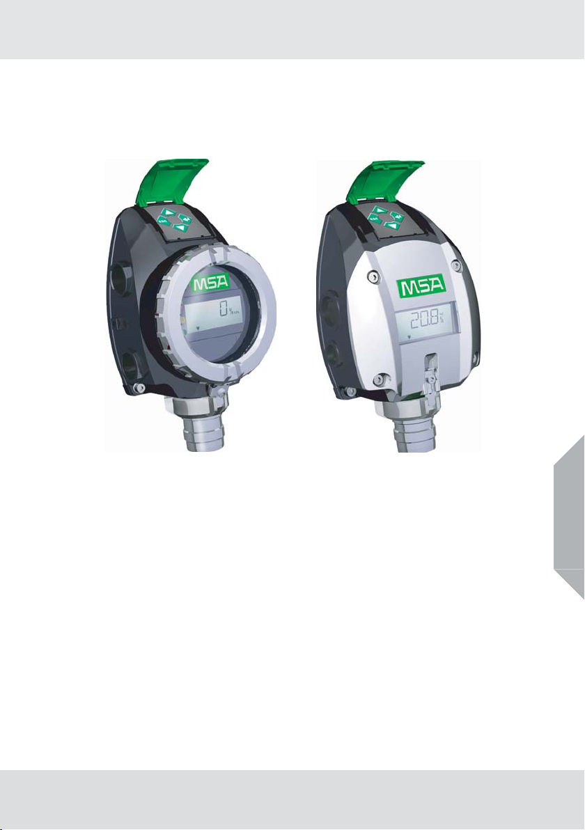
PrimaX P PrimaX I
flameproof version
Fig. 1 PrimaX Gas Transmitter
PrimaX P
The PrimaX P is a gas transmitter with an aluminum enclosure. This is a flameproof version for the
detection of combustible or toxic gases or oxygen.
PrimaX I
The PrimaX I is a gas transmitter with a plastic enclosure. It is available as a general purpose version
(not intended for hazardous area) or intrisically safe version. Both versions are designed for a detection
of toxic gases or oxygen.
general purpose version, or
intrinsically safe version
2.2 Overview
The device is factory-calibrated and delivered ready for installation. Each device is configured and calibrated for only one specific gas or vapor.
The enclosures vary depending on the particular version. The electrical parts and interfaces have the
same basic functionality.
The device has:
• a quick and easy pluggable sensor,
• a four digit liquid crystal display (LCD),
• a key pad with a cover
• a detachable backplate for installation on a wall or on a pipe
The device operates with a 4 – 20 mA output signal.
GB
PrimaX
8
Page 9
Description
1
2
3
7
8
9
4
6
5
10
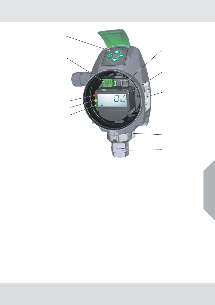
Fig. 2 Exploded View (PrimaX P)
1 Terminal for power connection 6 Sensor
2 Keypad with cover 7 Red LED (PrimaX P only)
3 Connector for factory use 8 Yellow LED (PrimaX P only)
4 Display 9 Green LED (PrimaX P only)
5 Bayonet joint with interlock 10 Identification plate
PrimaX
GB
9
Page 10

Description
Sensors
Description PrimaX P PrimaX I
Detection of toxic gases X X
Detection of oxygen X X
Detection of combustible gases X
The device operates with a 4 – 20 mA output signal.
As an optional feature additional modules are available for these configurations of PrimaX transmitter:
Modules PrimaX P PrimaX I
HART module X X
HART + Relays module X -
HART+ Relays module with galvanically isolated analogue
output
For more information on the HART module → chapter 4.7 "Optional HART Module and Relay".
X-
PrimaX
GB
10
Page 11
3 Installation
The device should be installed where gas leaks are expected. The installation position depends on the
gas density, either in the upper area of the room under the ceiling for gases lighter than air or close to
the ground for gases heavier than air. Also consider how air movement may affect the ability of the
device to detect gas. The display on the front of the instrument must always be clearly visible, the view
must not be obstructed.
Before beginning the installation, check that the delivered components are complete
and correct, referring to the shipping documents and the sticker on the shipment carton.
When preparing the assembly, make sure that the mounting arrangement is correct for
the particular device.
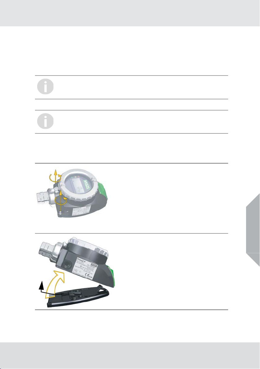
3.1 Mechanical Installation
Preparation
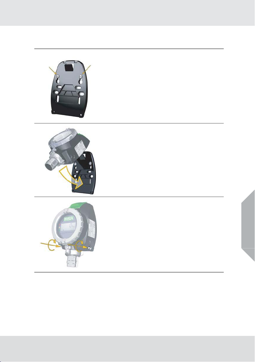
To install the device, first remove the backplate.
Installation
Undo Screws
(1) Unscrew the device.
Remove Device
(2) Remove the device from the backplate by lifting up
the lower edge as shown.
PrimaX
GB
11
Page 12
Wall or Pipe Mounting
For pipe mounting a pipe mounting kit is necessary (→ chapter 8.6 "Pipe Mounting Kit").
Install the Backplate
(1) Use the two keyhole slots for attaching the mounting plate
to the wall. Use 6mm diameter screws and suitable
plugs.
(2) For a wall installation use the backplate as a template for
drilling the holes for the two fixing screws, for a pipe
installation use the pipe clip.
(3) Attach the backplate to the wall or the pipe clip with M6 x
20 screws.
a) The hitch should point away from the wall or pipe.
b) The straight edge of the backplate should be at the
bottom.
Attach the Device to the Backplate
(4) Attach the device to the top of the backplate.
(5) Fold down the device, till it is closed to the backplate.
Installation
Fasten Device
(6) Screw the device to the backplate.
PrimaX
GB
12
Page 13
3.2 Electrical Installation
1 2
3 4
1 2
3 4
Instructions for Electrical Connection
WARNING!
The device must be installed only in compliance with the applicable regulations, otherwise the safe
operation of the instrument is not guaranteed.
• Shielded cable for measuring devices is recommended.
• Always observe maximum cable lengths and cross-sections (→ chapter 6.2 "Cable Lengths and
Cross-sections").
• Water or impurities can penetrate the instrument through the cable. In hazardous areas, it is
recommended to install the cable in a loop just before entry into the instrument or to slightly bend
it to prevent water from entering.
The power supply is defined as 24 VDC. If the input supply voltage at the terminal of the
transmitter is less than 10 V, the device will shut down. The 24 V power supply shall fulfill
the requirements for a PELV/SELV of EN 60950.
Operating the PrimaX I version in hazardous areas requires an intrinsically safe power
supply.
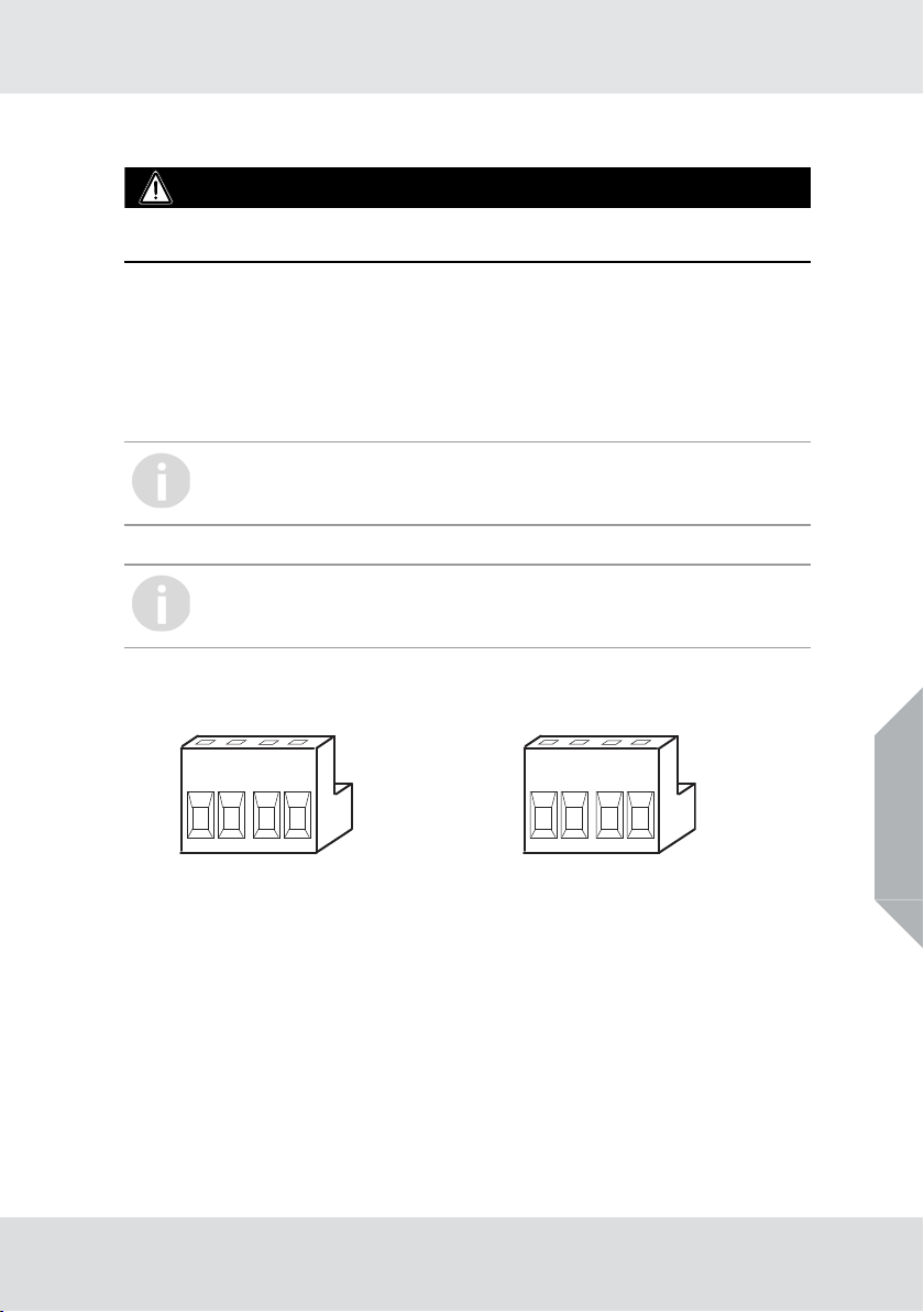
Electrical Connection - PrimaX P
Terminal PrimaX P
Installation
Fig. 3 Terminal PrimaX P (3-wire sensor) Fig. 4 Terminal PrimaX P (4-wire sensor)
1 Power supply (+), 24 V DC 1 Power supply (+), 24 V DC
2 0 V DC 2 0 V DC
3 4–20mA (Signal) 3 4–20mA (Signal)
4 empty 4 Isolated ground
PrimaX
GB
13
Page 14
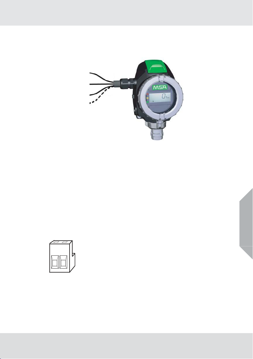
PrimaX P
Power supply (+) 24 V DC
0 V DC (-)
4–20mA(Signal)
Isolated ground
Fig. 5 3-wire/4-wire connection - PrimaX P
(1) Unscrew the interlock between cover and bayonet joint of sensor.
(2) Unscrew the aluminum lid of the enclosure.
(3) Unplug the 4-way terminal block.
The block is located behind a plastic cover above the display.
(4) Unscrew clamping nut at the cable gland.
(5) Put clamping nut on the cable.
(6) Insert cable for connection into the device.
(7) Connect cable to terminal.
Use a shielded cable with 3 wires for the 3-wire sensor.
Use a shielded cable with 4 wires for the 4-wire sensor.
(8) Tighten cable gland clamping nut, check that cable cannot move within the cable gland.
(9) Replace enclosure lid and secure the interlock.
Electrical Connection - PrimaX I
Terminal PrimaX I
Installation
GB
1 2
Fig. 6 Terminal PrimaX I
1 Power supply (+), 24 V DC
24–20mA (Signal)
PrimaX
14
Page 15

PrimaX I
Power supply (+)
4 – 20 mA (Signal)
Fig. 7 2-wire connection - PrimaX I
(1) Remove plastic cover.
It is bolted with 4 screws.
(2) Remove the 2-way terminal block.
It is located behind a plastic cover above the display.
(3) Unscrew clamping nut at the cable gland.
(4) Put clamping nut on the cable
(5) Insert cable for connection into the device.
(6) Connect cable to terminal.
a) Use a 2-wire shielded cable.
(7) Tighten cable gland clamping nut, check that cable cannot move within the cable gland.
(8) Replace plastic cover, tighten the screws and secure the interlock.
Installation
PrimaX
GB
15
Page 16

4Operation
1
2
65
3
7
4
The device is factory-calibrated and delivered ready for installation. Each device is
configured and calibrated for only one specific gas or vapor.
Fig. 8 Display overview
1 Measuring value/Menu//Text dimensions 5 Calibration
2 Units 6 Alive signal (flashing)
3 LOC, alarm indication (optional) 7 Maintenance
4 Signal for an active communication
Operation
PrimaX
GB
16
Page 17
4.1 Startup
1
4
2
3
During startup a self-test is performed and the output signal is set to the service current (default
3.0 mA). The following information is displayed:
Display Test
The display shows all segments.
Note: The PrimaX P also shows all LEDs and afterwards the yellow LED is flashing during the startup
procedure.
Software Version
The display shows the firmware version.
Sensor
The display shows the configured type of sensor operating with each individual detector, e.g.:
COMB (combustible), CO, H
Range
The display shows the measuring range predefined for the gas detector, e.g.: 100% LEL.
Countdown
The countdown for sensor stability is displayed.
Normal Operation
After countdown, the gas concentration (ppm, Vol%, % LEL, % UEG, mg/m
symbol flashes to indicate alive status.
S.
2
3
4.2 Menu Sequence
Operation
) is displayed. The heart
GB
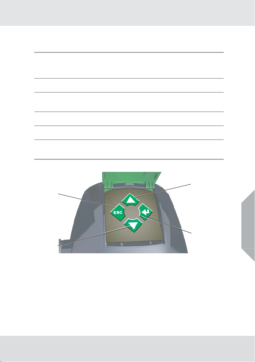
Fig. 9 Keypad - operating buttons
1 ESC button 3 ENTER button
2 UP button 4 DOWN button
To navigate in the menu sequence, 4 buttons are available.
In general:
(1) Press ENTER to get access to a menu sequence.
(2) Press UP or DOWN until the desired menu is displayed.
(3) Press ENTER to get access to a menu.
(4) Press ESC to cancel the process.
PrimaX
17
Page 18
The following table lists the menu items. Detailed descriptions can be found in the chapters 4.3 "Calibration", 4.4 "Maintenance and Info" and 4.5 "Password".
Menu item Text Password?
M-01 Calibration Yes
M-02 ZERO Calibration Yes
M-03 Show Test Gas Concentration No
M-04 Setup Calibration Yes
M-05 Sensor Exchange Yes
M-06 LCD and LED Test No
M-07 Loop Test Yes
M-08 Device Info No
M-09 Sensor Info No
M-10 Changing the Range Yes
M-00 Reset Alarm Ye s
4.3 Calibration
WARNING!
The test gases used for calibration are possibly posing a health risk. Proper ventilation or extraction
has to be ensured.
General
The calibration must be done at regular intervals in accordance with applicable national and regional
regulations.
The device is calibrated at the factory. Nevertheless, it is recommended to recalibrate the device after
installation. The frequency of calibration depends on the duration of use and the chemical exposure of
the sensor. New sensors must be calibrated frequently until it is clear from the calibration data that they
have stabilised. Suitable regulators and pipes for calibration must be used.
Operation
GB
A calibration cap is recommended for sensor calibration,
flow rate 1l/ min (± 20%).
Connect power to the device at least one hour before attempting a calibration.
Carry out the calibration during commissioning as well as at regular intervals. This
ensures optimum operation of the sensor.
It is recommended that all calibration components are connected before starting a calibration as it is necessary to apply test gas to the device during a countdown.
PrimaX
18
Page 19

Operation
When monitoring flammable gas in safety related applications the PrimaX must be calibrated with a known concentration of the gas being monitored.
The lower explosive limits (LEL) of the gases and vapors in the following example were taken from EN
60079-20-1. Local regulations may specify different LEL values; always ensure the correct values are
used.
It is recommended that the PrimaX zero is calibrated using clean air, free of measuring gas, and calibration gas of approximately 50 % of measuring range (comb. and TOX) in air of the gas being monitored. The recommended calibration gas for oxygen is 50% of measuring range, but for a measuring
range 0-25 vol% O
Calibration example for Methanol
Methanol calibration gas concentration being used = 3,5 Vol%
Methanol volume concentration for 100%LEL = 6,0 Vol%
Methanol calibration gas concentration in %LEL
, the device can be calibrated using 20.9 vol% O2.
2
For oxygen a zero calibration with gas is not required, it is performed internally.
3,5 Vol% CH
Calibration Procedure
The calibration can be performed as a manual or an automatic calibration (→ M-04).
Automatic Calibration (automatic): a countdown is displayed. After the countdown the value is
measured and displayed. When the value is stable the current value is selected automatically.
Manual Calibration (manual): the measuring value is displayed. When the value is stable press
ENTER to select the current value.
Waiting for calibration gas
After starting any calibration step, calibration gas (zero or test gas) must be applied until calibration
step is finished.
4
O x
100% LEL
6,0 Vol% CH
PrimaX
O
4
= 58,3 % LEL
GB
19
Page 20

Calibration Steps
The calibration procedure can be canceled at any time by pressing ESC. The previous
transmitter calibration will be used.
(M-01) - ZERO and SPAN Gas Calibration
(1) Press ENTER and select menu 1.
(2) Press ENTER button.
(3) Enter password (→ chapter 4.5 "Password").
(4) Apply zero gas (synthetic air).
(5) Wait until countdown is finished (automatic) or press ENTER (manual).
OK is displayed.
(6) Apply test gas.
(7) Wait until calibration is finished (automatic) or press ENTER (manual).
OK is displayed.
Idle time countdown starts, during this time the test gas can be removed and the output
signal remains on service current level.
(8) Remove test gas during the countdown.
(M-01) - Oxygen Calibration
(1) Press ENTER and select menu 1.
(2) Press ENTER button.
(3) Enter password (→ chapter 4.5 "Password").
(4) Apply synthetic air.
(5) Wait until countdown is finished (automatic) or press ENTER (manual).
OK is displayed.
(6) The device goes to measuring mode.
(M-02) - ZERO Gas Calibration
(1) Press ENTER and select menu 2.
(2) Press ENTER button.
(3) Enter password (→ chapter 4.5 "Password").
(4) Apply zero gas (synthetic air).
(5) Wait until calibration is finished (automatic) or press ENTER (manual).
OK is displayed.
(6) The device goes to measuring mode.
4.4 Maintenance and Info
(M-03) - Show Test Gas Value
(1) Press ENTER and select menu 3.
(2) Press ENTER button.
Test gas concentration is displayed.
(3) Press ENTER button to go back to Menu or ESC to go back to measuring mode.
(M-04) - Setup Calibration
This menu is used to set the test gas concentration for span calibration and all calibration countdown
times.
(1) Press ENTER and select menu 4.
(2) Press ENTER button.
(3) Enter password (→ chapter 4.5 "Password").
Operation
GB
PrimaX
20
Page 21
Operation
(4) Set the test gas concentration with the UP or DOWN button.
(5) Press ENTER button.
(6) Set the zero calibration countdown time in seconds with the UP or DOWN button.
a) Note: time = 0 → (manual) zero calibration, otherwise an (automatic) calibration is
performed by the device.
(7) Press ENTER button.
(8) Set the span calibration countdown in seconds with the UP or DOWN button.
a) Note: time = 0 → (manual) span calibration, otherwise an (automatic) calibration is carried
(9) Press ENTER button.
(10) Set the idle time countdown in seconds with the UP or DOWN button.
(11) Press ENTER button.
(M-05) - Sensor Exchange
This menu initiates the initial calibration and resets the sensor lifetime counter.OX/TOX sensors can
be exchanged under power (hot swapped) with this function.
Hot swaps must not be carried out for COMB sensors.
Only OX/TOX sensors can be exchanged with this menu.
For COMB sensors with this menu only the initial calibration is initiated and the sensor life time is reset.
out by the device.
WARNING!
If an (OX/TOX) sensor is connected: If a COMB sensor is connected:
(1) Press ENTER and select menu 5.
(2) Press ENTER button.
(3) Enter password (→ chapter 4.5 "Pass-
word").
• An hourglass symbol is shown to signify the
time span (max. 15 min) during which it is
possible to hot-swap a sensor without triggering an error code
(5) Change the sensor during this time span.
(6) Press ENTER or ESC to start the running-
in time countdown.
(7) (Perform a ZERO and SPAN or Oxygen
calibration (M-01).
(1) Press ENTER and select menu 5.
(2) Press ENTER button.
(3) Enter password (→ chapter 4.5 "Pass-
word").
(4) (Perform a ZERO and SPAN calibration (M-
01).
GB
Sensors that are no longer required have to be disposed of in an environmentally
compatible way.
(M-06) - LCD/LED Test
LCD and LED test (LED only available in PrimaX P). All segments will be displayed and the LEDs will
flash sequentially.
(1) Press ENTER and select menu 6.
(2) Press ENTER button.
PrimaX
21
Page 22

Operation
(M-07) - Loop Test
In this menu a 4 - 20 mA loop test will be performed.
(1) Press ENTER and select menu 7.
(2) Press ENTER button.
(3) Enter password (→ chapter 4.5 "Password").
The loop test mA value is displayed (default value = 12 mA).
(4) Press UP or DOWN to change the value.
(5) Press ENTER button to start the test.
(6) Press ENTER button to go back to menu or ESC to go back to measuring mode.
(M-08) - Device Information
In this menu device information is shown, i.e. gas type, measuring range, firmware version.
(1) Go through the information with the ENTER button.
(M-09) - Sensor Information
This menu shows the minimum and maximum measured gas concentrations, which can be reset by
holding the UP or DOWN button.
It shows the sensor life time in months since sensor exchange (→ M-05).
If a COMB or a TOX sensor is connected this menu shows the response time (as calculated during
zero span calibration).
If an OX/TOX sensor is connected this menu shows the measured mV value.
If a COMB sensor is connected this menu shows the detector (U
voltage (U
(1) Go through the information with the ENTER button.
) in mV.
X
), compensator (UK) and differential
D
PrimaX
GB
22
Page 23

(M-10) - Range Selection
WARNING!
Test gas concentration has to be checked and device has to be calibrated if the range is changed.
This menu allows to set up the optional measuring ranges for connected OX/TOX sensors.
(1) Press ENTER and select menu 10.
(2) Press ENTER button.
(3) Enter password (→ chapter 4.5 "Password").
(4) Press UP or DOWN button to select the range and/or the measuring unit (TOX: ppm, mg/m
COMB: LEL, UEG).
(5) Press ENTER button.
(M-00) - Reset Alarm
menu to reset a LOC of combustible sensor or an alarm. It appears only in the menu if there is a latched
LOC or alarm.
(1) Press ENTER and select menu 0.
(2) Press ENTER button.
(3) Enter password (→ chapter 4.5 "Password").
OK is displayed.
The calibration is set to invalid and service current is supplied until recalibrated.
Success message confirms that latched alarm is reset.
4.5 Password
Menus which should only be changed by qualified and authorized persons are locked by a four digit
password.
Operation
3
;
The default password is 0000.
After entering the password menu, the values of the digits will be set from left to right:
(1) Press UP or DOWN to change the value.
The value will be increased or decreased.
(2) Press ENTER to get to the next digit.
With ESC, one digit can be backspaced.
If all four digits are entered, the password will be validated.
PrimaX
GB
23
Page 24

4.6 Changeable Parameters
Values default minimum maximum
regarding sensor (e.g.: CO
Span/Test Gas Value
Zero Calibration Time 30 s 0 s 2000 s
Span Calibration
Time
Idle Time after calibration
Range See 6.4 "List of Detectable Gases" List of detectable gases
Loop Test 12 mA
= 60ppm, H
O
= 20.8 vol%, combus-
2
tible = 50% LEL)
30 s 0 s 2000 s
30 s 10 s 2000 s
S 10ppm,
2
10% of Range 100% of Range
2 mA with
2-wire version
0 mA with
3/4-wire version
4.7 Optional HART Module and Relay HART
Introduction
"HART" is an acronym for Highway Addressable Remote Transducer. The HART Protocol makes use
of the Bell 202 Frequency Shift Keying (FSK) standard to superimpose digital communication signals
at a low level on top of the 4 - 20 mA.
The HART Protocol provides two simultaneous communication channels:
the 4 - 20 mA analog signal and a digital signal. The 4 - 20 mA signal communicates the primary
measured value (in the case of a field instrument) using the 4 - 20 mA current loop. Additional device
information is communicated using a digital signal that is superimposed on the analog signal.
PrimaX is registered with the HART foundation and can be accessed at
http://www.hartcomm.org/
The device is available with an optional HART module or a module with HART and Relays for alarm
and failure. It uses the HART Protocol Revision 7 and can only communicate with HART Masters who
support revision 7 or higher.
Operation
22 mA
GB
The following HART functions are also available:
ZERO SPAN Calibration / Oxygen Calibration; ZERO Calibration; Sensor Exchange;
LCD/LED Test; Loop Test; Range setup; Reset alarm; Readout all measured data and
information.
PrimaX
24
Page 25

Electrical installation
1
1
Fig. 10 HART ports
1 Optional HART port
For wiring diagrams → chapter 10.6 "Wiring Diagrams".
Relays
Relay nominal switching capacity (resistive load):
Alarm Relay 2A / 30V DC
Failure Relay 2A / 30V DC
Operation
Fig. 11 Location of Relay
1 Relay Terminals
PrimaX
GB
25
Page 26

Operation
132
132
ALARM FAILURE
Fig. 12 Relay Terminals
Alarm Relay Failure Relay
1 Normally closed energised(NC) 1 Normally closed energised(NC)
2 Common (COM) 2 Common (COM)
3 Normally open energised(NO) 3 Normally open energised(NO)
4.8 Relay Operation Startup
If relays are used the alarm threshold will be displayed at startup
Menu Sequence
Menu item Text Password?
M-11 Relay Info No
M-12 Relay Setup Yes
M-13 Relay Test Yes
(M-11) - Relay Info
(1) Press ENTER and select menu 11.
(2) Press ENTER button.
(3) Go through the information with the ENTER button.
• The alarm threshold and if the alarm is activated with a rising or falling gas concentration.
• if an alarm would be latched.
• the alarm relay delay time in seconds.
• if the alarm relay is normally energised.
• the failure relay delay time in seconds.
• if the failure relay is normally energised.
It shows:
GB
PrimaX
26
Page 27

(M-12) - Relay Setup
(1) Press ENTER and select menu 12.
(2) Press ENTER button.
(3) Enter password (→ chapter 4.5 "Password").
(4) Set the alarm threshold with the UP or DOWN button.
(5) Press ENTER button.
(6) Set rising or falling alarm option with the UP or DOWN button.
(7) Press ENTER button.
(8) Set if latched with the UP or DOWN button.
(9) Press ENTER button.
(10) Set the alarm relay delay with the UP or DOWN button.
(11) Press ENTER button.
(12) Set alarm relay normally energized option with the UP or DOWN button.
(13) Press ENTER button.
(14) Set the failure relay delay with the UP or DOWN button.
(15) Press ENTER button.
(16) Set the failure relay normally energized option with the UP or DOWN button.
(17) Press ENTER button.
(M-13) - Relay Test
(1) Press ENTER and select menu 13.
(2) Press ENTER button.
(3) Enter password (→ chapter 4.5 "Password").
(4) The relays are now Switched and can be tested.
(5) Press ENTER button to go back to menu or ESC to go back to measuring mode.
Operation
PrimaX
GB
27
Page 28

Changeable Parameters for Relays
Values default minimum maximum
Alarm threshold
Alarm relay normally energized yes yes no
Latch alarm yes yes no
Alarming direction
Alarm delay time 0 s 0 s 600 s
Failure relay normally energized
Failure relay delay time 0 s 0 s 600 s
Setting required for ATEX conditions:
Latch alarm = yes: Alarm output self-retaining
Alarm delay time = 0s, no delay of output
Failure relay normally energized = yes
Changeable Parameters with HART
For all parameters which can be changed over keypad see chapter 4.6 "Changeable
Parameters"
30% of Range
= 20 vol%)
(O
2
decrease;
O
2
other increase
yes yes no
5 % of Range 100% of Range
Increasing Decreasing
Operation
Values default minimum maximum
Password 0000 0000 9999
Ta g M SA - -
Description PrimaX - -
Long tag - -
Message - -
Enable LOC if combustible enable enable disable
In case of very high flammable concentrations >100%LEL the device is able to lock all
outputs (LOC). This function shall be used for standalone applications according to
ATEX requirements.
PrimaX
GB
28
Page 29

Operation
Output States
State Failure Relay Alarm Relay
Normal
Star tup
Calibration
Latched voltage overrange Switched
Loop not connected Switched
Underrange Switched
Error Switched
Safety critical error Switched
LOC (combustible) Switched
Latched LOC (combustible) Switched
Alarm threshold exceed Switched
Switched: the relay state has switched from the normal state. The normal state can be set to energised
if alarm/failure or de-energised if alarm/failure. Normally de-energised if alarm/failure meets the ATEX
and SIL requirements. In case of switched relays the device will go to the normal state when the related
condition (non-latched alarm and/or fail) has been removed. For additional information about output
states, see chapter 10 "Appendix"
LOC: The PrimaX Gas Monitor has been exposed to a high gas concentration (above the LEL), and
the over-range condition still exists.
Latched LOC: The PrimaX Gas Monitor has been exposed to a high gas concentration (above the
LEL), and there is a possibility that the over-range condition may still exist.
Startup state
(default: switched)
PrimaX
GB
29
Page 30

5 Maintenance
5.1 Changing the Sensors
DANGER!
Remove and reinstall sensors carefully, ensuring that the components are not damaged; otherwise the
approval may be adversely affected, wrong readings could occur, and persons relying on this product
for their safety could sustain serious personal injury or death.
Before changing the sensor, the Sensor Exchange mode must be activated. This
ensures the sensor must be calibrated after exchange and the sensor lifetime counter is
reset. See chapter 4.2 "Menu Sequence".
Remove Interlock
(1) Unscrew the socket head screw.
(2) Remove the interlock.
Maintenance
Remove Bayonet Joint
(3) Turn the bayonet ring counter-clockwise.
(4) Remove the bayonet ring by pulling it down.
PrimaX
GB
30
Page 31

Replace Sensor
(5) Unplug the sensor carefully.
(6) Plug in the new sensor carefully.
(7) Replace the bayonet ring.
(8) Replace the interlock.
Maintenance
PrimaX
GB
31
Page 32

6 Technical Data
6.1 Specifications
Enclosure
Dimensions in mm
(Height X Width X Depth)
Weight 1.6 kg 1.2 kg
Humidity 15 % to 90 % rel. humidity 15 % to 90 % rel. humidity
Power supply 19.2 V - 28.0 V 19.2 V - 28.0 V
Power consumption 3W 0.7W
Temperature range
(instrument)
Temperature range
(sensor)
Signal output
HART (option)
Relay (option)
Signal output tolerance 1 % 1 %
Pressure 80 – 120 kPa 80 – 120 kPa
Max. load resistance 300 Ohm 300 Ohm
Air velocity 0 – 6 m/s 0 – 6 m/s
PrimaX P PrimaX I
aluminum enclosure
flameproof
IP 67 ingress protection
220 X 162 X 100 220 X 162 X 81
-40 to +70 °C
see sensor
4 – 20 mA
yes
yes
plastic enclosure
intrinsically safe
IP 66 ingress protection
-40 to +70 °C
see sensor
4 – 20 mA
yes
no
Technical Data
Measuring Methods
Oxygen Electrochemical sensor
Toxic gases Electrochemical sensor
Combustible gases Thermo-catalytic sensor
Relay nominal switching capacity (resistive load):
Alarm Relay 2A / 30V DC
Failure Relay 2A / 30V DC
PrimaX
GB
32
Page 33

Refresh Rate of Output Signals
4 - 20 mA output signal (analog) 100 ms
Alarm (LED and relay) 100 ms
Failure (LED and relay) 100 ms
Display (measuring value) 1 s
Display (alarm) 2100 ms
6.2 Cable Lengths and Cross-sections
The maximum load resistance for all combinations is 300 Ohm.
Technical Data
Sensor type
Toxic Gases and Oxygen Sensors with
4 – 20 mA Signal Output (2- wire Sensor)
Catalytic Combustible Gas Sensor with
4 – 20 mA Signal Output (3- wire Sensor)
Toxic Gases and Oxygen Sensors with
4 – 20 mA Signal Output (3- wire Sensor)
Catalytic Combustible Gas Sensor with
4 – 20 mA Signal Output (4- wire Sensor)
Toxic Gases and Oxygen Sensors with
4 – 20 mA Signal Output (4- wire Sensor)
6.3 Performance Specifications
Warm u p time
Storage temperature
Crosssection
1.0 mm
1.5 mm
1.0 mm
1.5 mm
1.0 mm
1.5 mm
1.0 mm
1.5 mm
1.0 mm
1.5 mm
Combustible 95 s
OX/TOX 36 s
-40°C to +70°C
or temperature range of the sensor
Max. length at 24 V DC
2
2
without
relay
2
980 m 700 m
2
1470 m 1050 m
without
relay
2
3920 m 2000 m
2
5880 m 3000 m
2
2
2
2
1960 m
2940 m
with relay
with relay
with relay
420 m
630 m
1848 m
2772 m
GB
PrimaX
33
Page 34

6.4 List of Detectable Gases
Gas Default range Selectable range(s) Temperature Range
Ammonia (NH
Ammonia (NH
Carbon Monoxide (CO) 200 ppm
Chlorine (Cl
Hydrogen (H
Hydrogen Chloride (HCl) 30 ppm
Hydrogen Cyanide (HCN) 30 ppm
Hydrogen Sulphide (H2S) 50 ppm
Methane (CH
Nitric Oxide (NO) 100 ppm - -15 – 40 °C
Nitrogen Dioxide (NO
Oxygen (O
part no. 10112718
(recommended)
Oxygen (O
part no. 10148289
Propane (C
Sulphur Dioxide (SO
) 100 ppm 50 ppm -20 – 40 °C
3
) 500 ppm 1000 ppm -20 – 40 °C
3
) 10 ppm 5 ppm -20 – 40 °C
2
) 1000 ppm - -20 – 50 °C
2
) 100 % LEL - -40 –70 °C
4
)10ppm
2
)
2
)
2
) 100 % LEL - -40 – 70 °C
3H8
)50ppm
2
100 ppm
500 ppm
-20 – 50 °C
1000 ppm
10 ppm
20 ppm
-20 – 40 °C
10 ppm
20 ppm
-40 – 40 °C
50 ppm
10 ppm
20 ppm
-40 – 50 °C
100 ppm
20 ppm
100 ppm
-20 – 50 °C
25 vol. % 10 vol. % -30 – 55 °C
25 vol. % 10 vol. % -20 – 50 °C
10 ppm
20 ppm
-20 – 50 °C
100 ppm
Technical Data
GB
Gases Zero drift Full scale drift Zero deviation
Lower limit of the
measuring range
CO ≤ 2 ppm/month ≤ 5 %/month ≤ 4 % of full scale 3 % of full scale
H
S ≤ 2 ppm/month ≤ 5 %/month
2
≤ 2 % full scale, at
least 1 ppm
1 % full scale, at least 1
ppm
PrimaX
34
Page 35

Technical Data
Resolution of display
Measuring range Resolution
1 to 10 0.1
25 Vol % oxygen 0.1
10 to 2000 1
Response time (diffusion mode)
Oxygen Response time Recovery time
t20 t90 t10
≤8s ≤ 25 s ≤ 25 s
Toxic Response time Recovery time
t90 t10
CO ≤20 s ≤ 44 s
H
S ≤12 s ≤ 32 s
2
Combustible Response time Recovery time
t50 t90 t50 t10
Methane ≤ 10 s ≤ 18 s ≤ 10 s ≤ 18 s
Propane ≤ 12 s ≤ 20 s ≤ 12 s ≤ 20 s
Combustible Response time Recovery time
t50
*)
t90
*)
t50
*)
t10
1-Ethoxy-2-Propanol ≤ 20 ≤ 48 ≤ 20 ≤ 48
Hydrogen ≤ 10 ≤ 18 ≤ 10 ≤ 18
Methane ≤ 10 s ≤ 18 s ≤ 10 s ≤ 18 s
Propane ≤ 12 s ≤ 20 s ≤ 12 s ≤ 20 s
*)
Response times with calibration cap and a flow rate of 1l / min
The response time will be increased up to 60 seconds by using the Sensor gard.
PrimaX
*)
GB
35
Page 36

6.5 Sensor Response to Interferants
Interference factors may differ from sensor to sensor and with life time.
It is not advisable to calibrate with interference gases.
This table does not claim to be complete. The sensor might also be sensitive to other
gases.
Gas Sensor Interferant
Combustible wide variety of combustible gases and vapours
Ammonia (NH
Ammonia (NH
) 100 ppm
3
) 1000 ppm
3
Carbon Monoxide (CO)
Chlorine (Cl
Hydrogen (H
)
2
)
2
Hydrogen Chloride (HCl)
Hydrogen Cyanide (HCN)
Hydrogen Sulphide (H
2
Nitric oxide (NO)
S)
20 ppm H
2 ppm
30 ppm Cl
5 ppm
200 ppm SO
-20 ppm
100 ppm NO
69 ppm
100 ppm NO
-5 ppm
1 ppm Br
1 ppm
10 ppm NO
4.5 ppm
300 ppm CO
<60 ppm
10 ppm HCN
3 ppm
0.2 ppm AsH
0.7 ppm
20 ppm H
60 ppm
0.1 ppm PH
0.3 ppm
100 ppm NO
-5 ppm
100 ppm Cl
-9 ppm
100 ppm HCN
1 ppm
20 ppm HCN
5 ppm
S
2
2
200 ppm H
S
2
120 ppm
2
100 ppm H
2
40 ppm
2
2
2.4 ppm ClO
2
0.55 ppm
2
0.25 ppm O
3
0.11 ppm
15 ppm H
S
2
<3 ppm
100 ppm C
2H4
80 ppm
3
5 ppm Cl
2
< +/- 0.1 ppm
S
2
100 ppm NO
45 ppm
3
20 ppm SO
2
8 ppm
10 ppm NO
2
-7 ppm
2
100 ppm NO
2
-21 ppm
100 ppm SO
2
1 ppm
10 ppm NO
2
3.5 ppm
Technical Data
10 ppm NO
6.5 ppm
100 ppm ethanol
4 ppm
20 ppm H
0.1 ppm
35 ppm NO
10 ppm
20 ppm HCN
7 ppm
10 ppm NO
< +/- 0.5 ppm
100 ppm NO
1 ppm
20 ppm SO
6 ppm
2
S
2
2
2
GB
PrimaX
36
Page 37

Technical Data
Gas Sensor Interferant
50 ppm NO
<-5 ppm
Nitrogen Dioxide (NO2)
400 ppm H
<0.1 ppm
20 ppm NH
2
3
< 0.1 ppm
200 ppb O
3
<120 ppm
Oxygen (O
Sulphur Dioxide (SO
6.6 PrimaX P List of Combustible Gases and Vapours detectable with Catalytic Sensor
) no data
2
)
2
Part No. 10112716
300 ppm CO
<3 ppm
Relative response factors of tested gases with reference to Propane
For the gases or vapours shown in the tables of this chapter the response curves have been tested
according to EN 60079-29-1:2007. If the LEL of a substance was not listed in EN 60079-20-1:2010,
the LEL has been taken from the Chemsafe data base (Dechema, Frankfurt). Due to legal requirements other locally used LEL values might be mandatory. It is highly recommended that the gas
detector is exposed to clean air when calibrating the zero and a mixture of the target gas in air with a
concentration of approximately 50% LEL. If calibration with the target gas is not possible a reference
calibration can be performed with 0.85 % (v/v) Propane C
data given in the table of this chapter. These values are only valid for new sensors and, unless otherwise stated, they refer to an ambient temperature of 20°C. If using a reference gas to calibrate the gas
detector the displayed values may vary by up to +/- 20% from the target gas concentration.
Reference calibration example for 50% Methanol:
20 ppm SO
<-15 ppm
20 ppm H
<-35 ppm
50 ppm C
< 0.1 ppm
5 ppm NO
-5 ppm
2
10 ppm Cl
2
<80 ppm
S
2
400 ppm CO
<0.1 ppm
2H4
5 vol% CO
2
< 0.1 ppm
2
in air and using the relative response
3H8
(1) Relative response factor for Methanol from table = 0.62
Propane calibration gas concentration being used
(2)
C
3H8
= 0.89 Vol %
(3) Propane volume concentration for 100 % LEL = 1.7 Vol %
(4) Propane calibration gas concentration in % LEL
= 0.89 Vol % C
3H8
x
100 % LEL
1.7 Vol % C
3H8
= 52.4 % LEL
(5) Gas detector span setting = 52.4 % LEL x 0.62 = 32.5 % LEL
PrimaX
GB
37
Page 38

Technical Data
Gas CAS-No.
Acetaldehyde (C
O) 75-07-0 4.0 fluid 0.64
2H4
LEL
(vol%)
Response
time (s) (t50)
Response time
*)
(s) (t90)
Gas/
Fluid
Response
factor
*)
Acetic acid (C2H4O2) 64-19-7 4.0 fluid 1.51
Acetic anhydride
((CH
CO)2O)
3
108-24-7 2.0 fluid 1.56
Acetone (C3H6O) 67-64-1 2.5 ≤ 9 ≤ 24 fluid 0.94
Acetylene (C2H2) 74-86-2 2.3 gas 0.76
Acrylonnitrile (C3H3N) 107-13-1 2.8 fluid 0.75
Allyl alcohol (C3H6O) 107-18-6 2.5 fluid 0.90
Ammonia (NH3) 7664-41-7 15.0 gas 0.38
Benzene (C6H6) 71-43-2 1.2 fluid 1.21
1.3-Butadiene (C4H6) 106-99-0 1.4 gas 1.01
i-Butane ((CH3)3CH) 75-28-5 1.3 gas 1.20
n-Butane (C4H10) 106-97-8 1.4 gas 1.09
n-Butanol (Butylalcohol) (C
4H10
O)
71-36-3 1.4 fluid 1.40
2-Butanone (C4H8O) 78-93-3 1.5 ≤ 12 ≤ 31 fluid 1.13
i-Butylacetate
(C
O)
6H12
n-Butylacetate
(C
O)
6H12
110-19-0 1.3 fluid 1.48
123-86-4 1.2 fluid 1.56
Butylbenzene (C10H14) 104-51-8 0.8 fluid 3.85
1-Butylene (C4H8) 106-98-9 1.6 gas 0.94
i-Butylene (C4H8) 115-11-7 1.6 gas 0.93
Cyclohexane (C6H12) 110-82-7 1.0 fluid 1.49
Cyclopentane (C5H10) 287-92-3 1.4 fluid 1.05
Diethylether (C4H10O) 60-29-7 1.7 fluid 1.16
1.4-Dioxane (C4H8O2) 123-91-1 1.4 fluid 2.22
Ethane (C2H6) 74-84-0 2.4 gas 0.87
Ethanol (C2H6O) 64-17-5 3.1 ≤ 11 ≤ 31 fluid 0.89
Ethene (C2H4) 74-85-1 2.3 gas 0.77
1-Ethoxy-2 propa-nol
(C
5H12O2
)
1569-02-4 1.3 ≤ 14 ≤ 46 fluid 1.71
Ethyl acetate (C4H8O2) 141-78-6 2.0 ≤ 13 ≤ 46 fluid 1.12
Ethyl acrylate (C5H8O2) 140-88-5 1.4 fluid 1.45
Ethyl benzene (C8H10) 100-41-4 0.8 fluid 1.49
Ethylen oxide (C2H4O) 75-21-8 2.6 gas 0.99
Gasoline 65/95 64742-49-0 0.9 ≤ 10 ≤ 21 fluid 1.40
n-Heptane (C7H16) 142-82-5 0.85 fluid 1.75
n-Hexane (C6H14) 110-54-3 1.0 fluid 1.48
M
M
M
D
M
M
M
M
M
M
M
M
M
D
M
M
M
M
M
M
M
M
M
M
D
M
D
D
M
M
M
D
M
M
GB
PrimaX
38
Page 39

Technical Data
Gas CAS-No.
Hydrogen (H
) 1333-74-0 4.0 ≤ 6 ≤ 16 gas 0.53
2
LEL
(vol%)
Response
time (s) (t50)
Response time
*)
(s) (t90)
Gas/
Fluid
Response
factor
*)
Methane (CH4) 74-82-8 4.4 gas 0.55
Methanol (CH4O) 67-56-1 6.0 fluid 0.62
Methyl tert-butylether
(C
O)
5H12
1634-04-4 1.5 fluid 1.12
n-Nonane (C9H20) 111-84-2 0.7 fluid 1.85
n-Pentane (C5H12) 109-66-0 1.1 gas 1,38
Propane (C3H8) 74-98-6 1.7 ≤ 14 ≤ 24 gas 1.00
1-Propanol (C3H8O) 71-23-8 2.1 ≤ 10 ≤ 50 fluid 0.98
2-Propanol (C3H8O) 67-63-0 2.0 ≤ 11 ≤ 25 fluid 1.04
Propene (C3H6) 115-07-1 2.0 ≤ 8 ≤ 19 gas 0.85
Propylene oxide
(C
O)
3H6
75-56-9 1.9 fluid 1.15
Toluene (C7H8) 108-88-3 1.0 ≤ 15 ≤ 46 fluid 1.22
Vinyl chloride (C2H3Cl) 75-01-4 3.6 gas 1.08
Xylenes (C8H10) 1330-20-7 0.9 fluid 1.47
All response factors relate to propane (measured at 50 % LEL; 0.85 % (v/v))
*
Response times are with a flow through adapter and a gas flow of 1 l/min
D
Response factor defined by DEKRA EXAM
Response factor defined by MSA (not included in the EC-Type Examination Certificate BVS
M
10 ATEX E 009 X)
D
M
M
M
M
M
D
D
D
D
M
D
M
M
PrimaX
GB
39
Page 40

Approvals
7 Approvals
7.1 Marking, Certificates and Approvals according to the Directive 2014/34/EU (ATEX) and National Standards
PrimaX P
MSA Europe GmbH
Manufacturer:
Product: PrimaX P
Schlüsselstr.12
CH - 8645 Rapperswil-Jona
EC-Type Examination Certificate:
Standards:
Performance: EN 60079-29-1:2007, EN 50104:2010, EN 50271:2010
Gas:
Other gases:
Marking: Prima X P U
BVS 10 ATEX E009 X
EN 60079-0:2012 + A11:2013, EN 60079-1:2014,
EN 60079-11:2012, EN 60079-31:2014
Measure range: 0-100 % LEL
Methane, Propane, 2-Butanone, Acetone, Ethanol,
Ethyl acetate, (FAM-) Standard mineral spirit 65/95,
2-Propanol, Propene, Toluene, Hydrogen,
1-Ethoxy-2-Propanole (40 °C)
Oxygen: 0-10 % (V/V), 0-25 % (V/V)
PFG 11 G 001: EN 45544 -1:1999; EN 45544 -2:1999
Tox: H
S: 0-20 ppm; 0-100 ppm;
2
CO: 0-100 ppm; 0-1000 ppm
= 60 VDC
m
Main housing
Prima X
Combustible sensor
Prima X
Ox/Tox sensor
I 2G Ex db ia (ia) IIC T4/T6 Gb
II 2D Ex tb ia (ia) IIIC T130°C / T85°C Db IP 67
T4 -40°C ≤ Ta ≤ +70°C, T6 -40°C ≤ Ta ≤ +40°C
T130°C -40°C ≤ Ta ≤ +70°C,
T85°C -40°C ≤ Ta ≤ +40°C
Ex db IIC T4/T6 Gb
Ex tb IIIC T130°C / T85°C Db IP 67
T4 -40°C ≤ Ta ≤ +70°C ,T6 -40°C ≤ Ta ≤ +40°T130°C -40°C ≤ Ta ≤
+70°C ,
T85°C -40°C ≤ Ta ≤ +40°C
Ex ia IIC T4 Gb
Ex ia IIIC T135°C Db IP 67
-40°C ≤ Ta ≤ +70°C
GB
PrimaX
40
Page 41

Approvals
Option:
Special Conditions for Safe Use
• Do not open the instrument when energized.
• For dust applications the installation conditions according to EN 60079-31 has to be considered.
• Intensive electrostatic charging processes have to be prevented on the instrument label.
• The joint widths of the flameproof joint of this apparatus are in parts longer, and its gaps are in
In case of using the PrimaX Ex-Sensor, the complete device type PrimaX P is in accordance to
temperature class T6/T85°C, ambient temperature range -40°C ≤ Ta ≤ +40°C or to temperature class
T4/T130°C, ambient temperature range -40°C ≤ Ta ≤ +70°C
In case of using the PrimaX Ox-Tox-Sensor, the complete device type PrimaX P is in accordance to
temperature class T4/T130°C, ambient temperature range -40°C ≤ Ta ≤ +70°C
Avoid electrostatic charge on the temporary used calibration cap when used for calibration.
Cable gland
• M25 x 1,5;Torque 8 -12 Nm; only ATEX certified versions for gas and dust shall be used.
• NPT ¾"- 14; fixture with 2 layer PTFE sealing tape or according to the instructions of the NPT
The HART-interface is subject of this type examination certificate only for the purpose of maintenance
and parametrization.
When the HART-/ relay module is used the alarm shall be configured latching.
If a device with a combustible sensor is exposed to vibrations , calibration shall be done in sufficient
short intervals until it is verified that the device is not affected by the vibration stress.
After exposure of gas above the measuring range, the sensor has to be immediately calibrated/
adjusted, independent of the calibration interval. In the case of an adjustment the sensitivity of the
sensor has to be rechecked again after 24 hours.
HART Module Connector, only for temporary connection of an intrinsic safe HART Field
Communicator
P
≤ 200 mW, Uo ≤ 2,7 V, I0 ≤ 137 mA, Lo ≤ 10 µH, Co ≤ 1nF
o
≤ 5mW, Ui ≤ 5V, Ii ≤ 1mA, Li = 0, Ci = 0
P
i
Relay: switching voltage = 30 VDC; switching current = 2 ADC
parts shorter than the values of Table 2 of EN 60079-1:2014. For maintenance or repair contact
the manufacturer.
supplier; when removed, new PTFE sealing has to be used after reinstalling; only ATEX certified
versions for gas and dust shall be used.
GB
Quality Assurance Notification: 0158
Year of Manufacture: see Label
Serial Nr.: see Label
PrimaX
41
Page 42

PrimaX I
MSA Europe GmbH
Manufacturer:
Product: PrimaX I
EC-Type Examination Certificate: BVS 10 ATEX E009 X
Standards: EN 60079-0:2012 + A11:2013, EN 60079-11:2012
Performance EN 50104 :2010, EN 50271 :2010
Schlüsselstrasse 12
CH-8645 Rapperswil-Jona
Approvals
Gas: Oxygen: 0-10 % (V/V), 0-25 % (V/V)
Other gases:
Marking: Prima X I
Option:
Special conditions for safe use:
It is not allowed to open the key pad cover during usage in areas where EPL Ga, Group IIC is required.
Avoid electrostatic charge on the temporary used calibration cap when used for calibration.
Quality Assurance Notification: 0158
Year of Manufacture: see Label
Serial Nr.: see Label
PFG 11 G 001: EN 45544 -1:1999; EN 45544 -2:1999
Tox: H
S: 0-20 ppm; 0-100 ppm;
2
CO: 0-100 ppm; 0-1000 ppm
II 1G Ex ia IIC T4 Ga
-40°C ≤ Ta ≤ +70°C
II 2D Ex ia IIIB T135°C Db
-40°C ≤ Ta ≤ +40°C
Pi ≤ 700 mW, Ui ≤ 28 V, Ii ≤ 100 mA, Li = 0, Ci = 0
HART Module Connector, only for temporary connection of an intrinsic safe HART
Field Communicator
P
≤ 700 mW, Uo ≤ 28 V, I0 ≤ 100 mA, Lo ≤ 10 µH, Co≤ 1nF
o
≤ 5mW, Ui ≤ 5V, Ii ≤ 1mA, Li = 0, Ci = 0
P
i
GB
PrimaX
42
Page 43

7.2 Marking and Certificates according to IECEx
PrimaX P
MSA Europe GmbH
Manufacturer:
Product: PrimaX P
Schlüsselstrasse 12
CH-8645 Rapperswil-Jona
Approvals
IEC-Type Examination Certificate: IECEx BVS 10.0043 X
Standards:
Perfomance: none
Gas: see manual
Marking: Prima X P
Option:
IEC 60079-0:2011, IEC 60079-1:2014,
IEC 60079-11:2011 IEC 60079-31:2013
Main housing U
Ex db ia (ia) IIC T4/T6 Gb
Ex tb ia (ia) IIIC T130°C / T85°C Db IP 67
T4 -40°C ≤ Ta ≤ +70°C,T6 -40°C ≤ Ta ≤ +40°C
T130°C -40°C ≤ Ta ≤ +70°C,T85°C -40°C ≤ Ta ≤ +40°C
Prima X
Combustible sensor
Ex db IIC T4/T6 Gb
Ex tb IIIC T130°C / T85°C Db IP 67
T4 -40°C ≤ Ta ≤ +70°C ,T6 -40°C ≤ Ta ≤ +40°C
T130°C -40°C ≤ Ta ≤ +70°C, T85°C -40°C ≤ Ta ≤ +40°C
Prima X
Ox/Tox sensor
Ex d ia IIC T4 Gb
Ex ia IIIC T130°C Db IP 67
-40°C ≤ Ta ≤ +70°C
HART Module Connector, only for temporary connection of an intrinsic safe HART
Field Communicator
≤ 185 mW, Uo ≤ 2,7 V, I0 ≤ 137 mA, Lo ≤ 10 µH, Co≤ 1nF, Pi ≤ 5mW, Ui ≤
P
o
5V, I
≤ 1 mA, Li = 0, Ci = 0
i
Relays: switching voltage: 30 VDC;
switching current: 2 ADC
= 60 VDC
m
GB
PrimaX
43
Page 44

Approvals
Special conditions for safe use:
• Do not open the instrument when energized.
• For dust applications the installation conditions according to EN 60079-31 have to be considered.
• Intensive electrostatic charging processes on the instrument label have to be prevented on the
instrument label.
• The joint widths of the flameproof joint of this apparatus are in parts longer, and its gaps are in
parts shorter than the values of Table 2 of EN 60079-1:2014. For maintenance or repair contact
the manufacturer.
In case of using the PrimaX Ex-Sensor, the complete device type PrimaX P is in accordance to
temperature class T6/T85°C, ambient temperature range -40°C ≤ Ta ≤ +40°C or to temperature class
T4/T130°C, ambient temperature range -40°C ?≤ Ta ≤ +70°C
In case of using the PrimaX Ox-Tox-Sensor, the complete device type PrimaX P is in accordance to
temperature class T4/T130°C, ambient temperature range -40°C ≤ Ta ≤ +70°C
Avoid electrostatic charge on the temporary used calibration cap when used for calibration.
Cable gland: M25 x 1,5 ;Torque 8 -12 Nm; only ATEX certified versions for gas and dust shall be used.
NPT ¾”- 14; fixture with 2 layer PTFE sealing tape or according to the instructions of the NPT supplier;
when removed, new PTFE sealing has to be used after reinstalling; only ATEX certified versions for
gas and dust shall be used.
Quality Assurance Notification: 0158
Year of Manufacture: see Label
Serial Nr.: see Label
PrimaX
GB
44
Page 45

PrimaX I
MSA Europe GmbH
Manufacturer:
Product: PrimaX I
IEC-Type Examination Certificate: IECEx BVS 10. 0043 X
Standards: IEC 60079-0:2011, IEC 60079-11:2011
Performance: non
Gas: see manual
Schlüsselstrasse 12
CH-8645 Rapperswil-Jona
Approvals
Marking: Prima X I
P
≤ 700 mW, Ui ≤ 28 V, Ii ≤ 100 mA, Li = 0, Ci = 0
i
Option:
Special conditions for safe use:
• It is not allowed to open the key pad cover by use in areas where Category 1G, Group IIC is
required.
• Avoid electrostatic charge on the temporary used calibration cap when used for calibration.
Quality Assurance Notification: 0158
Year of Manufacture: see Label
Serial Nr.: see Label
HART Module Connector, only for temporary connection of an intrinsic safe HART
Field Communicator
P
≤ 700 mW, Uo ≤ 28 V, I0 ≤ 100 mA, Lo ≤ 10 µH, Co≤ 1nF
o
≤ 5mW, Ui ≤ 5V, Ii ≤ 1mA, Li = 0, Ci = 0
P
i
Ex ia IIC T4 Ga
-40°C≤ Ta ≤ +70°C
Ex ia IIIB T130°C Db
-40 °C ≤ Ta ≤ +40 °C
GB
PrimaX
45
Page 46

7.3 Special conditions for the safe use according to ATEX and SIL applications
Safety relevant parameters for the Gas Transmitters
Typ e B
Structure 1oo1 or 1oo2
HFT 0 or 1
PFD, PFH, SFF see table
λ
, λD, λDU, λ
tot
MTTR 72 h
T1 16 weeks (Proof-Test-Interval)
Possible structures and acquirable SILs
The following table shows, which structure has to be selected, to fulfil the requirements of a special SIL.
LDM = Low Demand Mode
HDM = High Demand or Continuous Mode
Structure 1oo1 XXX
Structure 1oo2 XXXXXX
Depending on the selected configuration and the sensor version, the following safety-relevant parameters have to be considered while implementing the safety loop:
DD
SIL1 SIL2 SIL3
LDM HDM LDM HDM LDM HDM
see table
Approvals
PrimaX
GB
46
Page 47

Approvals
General conditions for the safe use
• The application advice and the limitations of the manual have to be considered. For calibration
and maintenance, the regional and national regulations have to be considered.
• A defect transmitter has to be repaired within 72 hours.
• The HART
• The alarm conditions of the transmitter must be periodically checked together with the typical gas
calibration checks.
• The relays must be energised under normal conditions.
• The relay contacts must be protected with a fuse rated 0.6 of the nominal specified relay contact
current.
• The failure relay contacts must be safety related processed for warning purposes when the 4 to
20 mA link is not use for the alarm condition.
• The tests of the 4-20 mA - output signal and alarm conditions and the test of the alarm and fault
relays, LEDs and display have to be done during every calibration phase.
• The connected controller has to monitor the 4-20 mA signal current for values below 4 mA and
above 20 mA.
• For the correct use of the combustible sensor a minimum oxygen concentration of 10 Vol% is
necessary.
• The presence of catalytic poisons has to be avoided for the combustible sensor.
• A functional check/calibration check has to be done for the complete system.
• A visual check has to be done monthly.
• A system check has to be done every year.
• For the test gas, the gas has to be used which is defined for the measurement. The concentration
of the test gas has to be in the middle of the measure range.
• For zero gas, synthetic air has to be used.
• An adjustment has to be done under the following conditions:
difference at zero > +/- 5 % UEG
difference at sensitivity > +/- 20 % of the rated value
• If the calibration is inside of the valid tolerance, the calibration interval can be doubled.
• The maximum of the calibration interval is 16 weeks.
• The sensor has to be replaced if the sensor sensitivity during the operation is reduced to less than
50 % of the initial sensitivity.
• After exposure of gas above the measuring range, the sensor has to be immediately calibrated/
adjusted, independent of the calibration interval. In the case of an adjustment the sensitivity of the
sensor has to be rechecked again after 24 hours.
• If the appearance of catalytic poisons for the combustible sensor can not be avoided, the calibra-
tion interval has to be considerably reduced.
®
interface is not allowed to be used for the transmission of safety related data.
GB
PrimaX
47
Page 48

Approvals
Special conditions for SIL 2
• The use of the sensors in a High Demand or Continuous Mode is allowed only in a 1002 - struc-
ture.
• The outputs of the sensors (4-20 mA - loops and relay contacts) must to be monitored regarding
deviations.
Special conditions for SIL 3
• The use of the sensors is allowed only in a 1oo2 - structure.
• The outputs of the sensors (4-20 mA - loops and relay contacts) must to be monitored regarding
deviations.
PrimaX
GB
48
Page 49

Safety Relevant ParametersMSA
7.4 Safety Relevant Parameters [40°C]t
Application with Relay
Ammonia (NH
) 3737 2469 1269 415 854 88.9 67.3 7.9E-04 5.6 1.2E-05 1.2 4.2E-07 4.2 8.7E-09 8.7
3
Carbon Monoxide
λ
total
λ
S
fitfitfitfitfit%%
3187 2194 994 255 739 92.0 74.4 3.4E-04 3.4 7.0E-06 0.7 2.5E-07 2.5 5.3E-09 5.3
λ
D
λ
DU
λ
DD
SFF DC PFD
1oo1
PFD
% of
2
1oo1
SIL
PFD
1oo2
PFD
1oo2
% of SIL 3
PFD
1oo2
PFD
1oo2
PFD
1oo2
PFD
1/h % of SIL 1 1/h % of SIL 3
(CO)
Chlorine (Cl
) 4332 2766 1566 589 978 86.4 62.4 7.8E-04 7.9 1.7E-05 1.7 5.9E-07 5.9 1.3E-08 12.7
2
Combustible 6666 3933 2733 1066 1667 84.0 61.0 1.4E-03 14.3 3.1E-05 3.1 1.1E-06 10.7 2.4E-08 24.2
Hydrogen (H
Hydrogen Chloride
) 3737 2469 1269 415 854 88.9 67.3 7.8E-04 5.6 1.2E- 05 1.2 4.2E-07 4.2 8.7E-09 8.7
2
4297 2749 1549 578 970 86.5 62.7 1.0E-04 7.8 1.6E- 05 1.6 5.8E-07 5.8 1.2E-08 12.4
(HCl)
Hydrogen Cyanide
3995 2598 1398 490 907 87.7 64.9 7.5E-04 6.6 1.4E- 05 1.6 5.6E-07 5.6 1.2E-08 12.0
(HCN)
Hydrogen Sul-
phide (H
S)
2
Nitrogen Dioxide
)
(NO
2
Nitrogen Oxide
3187 2194 994 255 739 92.0 74.4 5.6E-04 3.4 7.0E-06 0.7 2.5E-07 2.5 5.3E-09 5.3
4237 2718 1518 561 958 86.8 63.1 7.5E-04 7.5 1.6E- 05 1.6 5.6E-07 5.6 1.2E-08 12.0
4877 3039 1839 748 1091 84.7 59.3 1.0E-03 10.0 2.1E- 05 2.1 7.5E-07 7.5 1.6E-08 16.4
(NO)
Oxygen (O
Sulphur Dioxide
)
(SO
2
) 6044 3622 2422 655 1767 89.2 73.0 8.8E-04 8.8 1.9E-05 1.9 6.5E-07 6.5 1.4E-08 14.2
2
4297 2749 1549 578 970 86.5 62.7 5.6E-04 7.8 1.6E- 05 1.6 5.8E-07 5.8 1.2E-08 12.4
1oo2
PrimaX
49
Page 50

Safety Relevant ParametersMSA
Application with 4-20 mA Current Output
λ
total
λ
S
λ
D
λ
DU
λ
DD
SFF DC PFD
1k
PFD
1oo1
PFD
1oo2
PFD
1oo2
PFD
1oo2
PFD
1oo2
PFD
1oo2
PFD
fit fit fit fit fit % % % of SIL 2 % of SIL 3 1/h % of SIL 1 1/h % of SIL 3
Ammonia
)
(NH
3
Carbon Mon-
1734 867 867 363 504 79.1 58.1 4.9E-04 4.9 1.0E-05 1.0 3.6E-07 3.6 7.6E-09 7.6
1183 592 592 202 389 82.9 65.8 2.7E-04 2.7 5.5E-06 0.6 2.0E-07 2.0 4.2E-09 4.2
oxide (CO)
Chlorine (Cl
) 2328 1164 1164 536 628 77.0 53.9 7.2E-04 7.2 1.5E-05 1.5 5.4E-07 5.4 1.1E-08 11.5
2
Combustible 4662 2331 2331 1013 1318 78.3 56.5 1.4E-03 13.6 3.0E-05 3.0 1.0E-06 10.1 2.3E-08 22.9
Hydrogen (H
Hydrogen
) 1734 1437 1 43 7 363 504 79 .1 5 8 .1 4 .9 E-0 4 4.9 1.0E- 05 1.0 3.6E- 07 3.6 7.6E-09 7.6
2
2294 1117 1117 526 621 77.1 54.1 7.1E-04 7.1 1.5E- 05 1.5 5.3E-07 5.3 1.1E-08 11.2
Chloride (HCl)
Hydrogen Cy-
1992 867 867 438 558 78.0 56.0 5.9E-04 5.9 1.2E- 05 1.2 4.4E-07 4.4 9.3E-09 9.3
anide (HCN)
Hydrogen Sul-
phide (H
2
Nitrogen Dioxide (NO
)
2
Nitrogen Oxide
1183 592 592 202 389 82.9 65.8 2.7E-04 2.7 5.5E-06 0.6 2.0E-07 2.0 4.2E-09 4.2
S)
2233 1147 1147 509 608 77.2 54.5 6.8E-04 6.8 1.4E- 05 1.4 5.1E-07 5.1 1.1E-08 10.8
2874 1437 1437 695 741 75.8 51.6 9.3E-03 9.3 2.0E- 05 2.0 7.0E-07 7.0 1.5E-08 15.2
(NO)
Oxygen (O
Sulphur Diox-
ide (SO
) 4040 2020 2020 602 1418 85.1 70.2 8.1E-04 8.1 1.7E-05 1.7 6.0E-07 6.0 1.3E-08 13.0
2
2294 1147 1147 526 621 77.1 54.1 7.1E-04 7.1 1.5E- 05 1.5 5.3E-07 5.3 1.1E-08 11.2
)
2
1oo2
PrimaX
50
Page 51

8 Accessories
For part numbers → chapter 9 "Spare Parts".
8.1 Calibration Cap
Using calibration cap allows span gas calibration procedure to be accurate in windy environmental
conditions.
The calibration cap is pushed on to the front of the sensor and is sealed by an O- ring. The surface
area S < 20 cm
Fig. 13 Calibration cap
The calibrating cap must be removed after completing the calibration!
The gas is supplied via either of the gas inlets by means of suitable flexible tube.
8.2 Sensor Gard
2
.
WARNING!
Accessories
Fig. 14 Sensor gard
The sensor gard should be fitted at all times except when using the flow through adapter or duct mount
kit.
Ambient weather condition can affect the gas mixture inside of the sensor gard. Use sensor gard for
functional test only. Calibration cap is recommended for sensor calibration.
Using the sensor gard will extend the response time, depending on the gas flow rate.
Gas flow rate: 1,0 l/min
PrimaX
GB
51
Page 52

8.3 Remote Calibration
Fig. 15 PrimaX with CalGard
The CalGard stainless steel remote calibration adaptor provides reliable operation of remotely installed
gas detectors working under harsh environmental conditions. Additionally, the CalGard allows remote
verification ("bump test") or instrument calibration of gases listed later in this section and oxygen via a
hose connection in the presence of wind speeds up to 6 m/s.
In normal measurement operation, the ambient air passes through the air vents into the remote calibrator directly to the sensor (diffusion operation). During a bump test or instrument calibration, the test
gas is supplied to the sensor via the hose connection at the bottom of the CalGard. An integrated
mechanism prevents the dilution and dispersion of test gas otherwise caused by external influences,
such as wind. This allows a fast response from the sensor to the applied test gas.
Once calibration is complete, the air inlet reopens to allow the monitoring of ambient air for gas without
the need for further user intervention.
Installation
For correct operation, PrimaX and CalGard must be used in a vertical position (hose connection
pointing downwards). The CalGard remote calibration adaptor can be attached to the sensor by
screwing on the thread of the detector.
Accessories
GB
The tube connector is adapted for tubes with an inner diameter of 5 mm.
In general the hose should be as short as possible in order to:
• Minimise the gas volume needed to flush the tube
• Reduce external influences (e.g. temperature shift, pressure, etc.)
• Minimise the lead time
Hose material should be adapted to the applied test gas, have no absorptive or adsorptive properties
and should be made from inert material such as teflon or polyethylene.
When using the CalGard in the hazardous area, a conductive hose must be used.
The free end of the test gas tube must be closed if no test gas is applied. This is to prevent gas or air
passing through the tube to the sensor, distorting the measurement or in the reverse pressure conditions, the ambient atmosphere escapes from the sensor at the free end of the tube.
PrimaX
52
Page 53

Accessories
To ensure proper function the CalGard remote calibration adaptor must be kept dry and free of any
contaminants, e.g. dust particles. Regular visual checks are recommended. Any contaminants must be
removed by blowing them off with clean, oil-free compressed air or with a dry brush. Ensure that the
air entrances are kept free from any coating, e.g. paint, grease or similar.
Operation
Calibration procedure can be carried out as described in chapter 4.3 "Calibration" of this manual
To compensate for possible deviations during measurement of flammable gases a calibration factor of
1.05 has to be applied.
Example: Calibration for methane.
Apply 40 %LEL methane and adjust to 1.05 x 40 = 42 %LEL
When using the CalGard for a remote calibration, the response time of the system increases
depending on the length of the test gas tubes used. If the calibration is done automatically, set the calibration setup (menu: M04) with sufficiently long countdown times for zero gas and calibration gas.
Example: When using a 10 metre long tube with an internal diameter of 5 mm and applying a gas flow
of 1 litre/min, the test gas takes a minimum of 20 sec to reach the CalGard remote calibration adaptor.
For safe flushing of CalGard, an additional 10 seconds has to be added to this calculation.
If the CalGard is being used with a control system (i.e. SUPREMA), please ensure the manual for the
controller has been read and understood.
The pressure in the test gas tube increases with rising test gas flow rates. A flow rate of 1500 ml/min
results in a pressure up to 600 hPa. This has to be considered if a flow meter is used which is affected
by the media pressure.
Material St. St. 316
Dimensions (in mm) 60 x 122 (diameter x height)
Weight 0.6 kg
Working temperature -30 °C to +70 °C
Storage temperature -30 °C to +70 °C
Max. wind speed up to 6 m/s
H
, CH4, C3H8, CO and H2S in air, O2 in N
Applicable test gases
2
(approval of other gases by MSA on request)
Recommended flow rate 1.0 l / min
Minimum flow rate 0,8 l / min
Maximum flow rate 1.5 l / min
2
GB
Response times
CH
4
C
3H8
O
2
CO t
H
St
2
t
50
t
50
t
50
50
50
PrimaX
≤ 15 s t90≤ 40 s
≤ 20 s t90≤ 55 s
≤ 10 s t90≤ 45 s
≤ 15 s t90≤ 45 s
≤ 20 s t90≤ 60 s
53
Page 54

8.4 Flow Through Adapter
Fig. 16 Flow through adapter
The flow through adapter is for use with a pumped sampling system.
Gas inlet/outlet thread: 1/8” NPT
Gas flow rate: 1.0 l/min
Using the flow through adapter will extend the response time, depending on the gas flow
rate.
8.5 Duct Mounting Kit
Accessories
Fig. 17 Duct mounting kit
Gas monitoring in air ducts can be performed by means of this duct mounting kit. When installing, the
direction of flow inside the duct must be towards the baffles.
The sensor can be calibrated via the gas calibration port, provided the duct is free of all gases to which
the sensor will respond. If the duct cannot be gas free, the sensor must be removed from the duct
during calibration.
The calibration port must be sealed again with the locking cap after calibration has been carried out.
Calibration should only be carried out with the calibration port if the air velocity is < 5 m/s in the air duct.
PrimaX
GB
54
Page 55

The performance of the duct mounting kit depends on various parameters and has to be
checked before usage. The kit was not part of the compliance test.
8.6 Pipe Mounting Kit
The PrimaX can be mounted vertically by fastening its back plane using two screws and washers.
Additionally, a pipe mount kit allowing the PrimaX to be fixed to pipes or poles is available as an accessory.
The kit consists of:
• one universal mounting plate
• one retaining plate for pipes with a diameter of 20 – 30 mm
• one retaining plate for pipes with a diameter of 30 – 50 mm
• two tightening straps for pipes with a diameter of 50 – 150 mm.
Accessories
Fig. 18 Mounting plate
NOTE: The Pipe mounting kit not included in the EC-Type Examination Certificate
BVS 10 ATEX E 009 X
Fig. 19 Retaining plate
PrimaX
Fig. 20 Tightening straps
GB
55
Page 56

8.7 Sensor Tag
Fig. 21 Sensor tag
Accessories
Fig. 22 Measurements sensor tag
The stainless steel label allows to identify and tag the location or installation of the instrument on the
site.
PrimaX
GB
56
Page 57

8.8 Sunshield
Fig. 23 Sunshield
Stainless steel plate to protect the transmitter from direct sunlight.
8.9 Universal HART Cable
Accessories
Fig. 24 Universal HART cable
Universal cable that will connect the PrimaX detector to any standard HART handheld (f.e. Emerson
375) using the HART connector.
PrimaX
GB
57
Page 58

9 Spare Parts
List of Accessories
Description Material Part No.
Sensor Gard Plastic 10113033
Flow Through Adapter St.St. 316 10113031
Duct Mounting Kit St.St. 316 10112790
Pipe Mounting Kit St.St. 316 10113032
Sensor Tag St.St. 316 10113034
Sunshield St.St. 316 10113035
Calibration Cap Plastic 10112789
CalGard St.St. 316 10150921
Universal HART cable (1.5 m) 10113036
PrimaX I Replacement Parts
Description Part No
Bayonet lock plate & screw 10113042
Sensor bayonet & cap 10113048
Mounting plate 10113041
Lid 10113045
Lid screws (set of 4) 10113046
Keyboard cover 10113040
Cable gland M25 x 1.5, 7 – 17 mm 10113039
Spare Parts
PrimaX P Replacement Parts
Description Part No
Bayonet lock plate & screw 10113050
Sensor bayonet and cap 10113058
Mounting plate 10113041
Lid 10113056
Keyboard cover 10113040
Cable gland Ex d II CT4 M25 x 1.5 10113038
Cable gland Ex d II CT4 ¾“ NPT 10113037
Replacement Sensors
Gas Range (optional) Part No.
Catalytic Sensor Combustible Gases (Only
PrimaX P version)
Ammonia (NH
Ammonia (NH
) 100 ppm (50 ppm) 10080225
3
) 1000 ppm (500 ppm) 10112719
3
100% LEL 10112716
PrimaX
GB
58
Page 59

Spare Parts
Gas Range (optional) Part No.
Carbon Monoxide (CO)
Chlorine (CL
Hydrogen (H
) 10 ppm (5 ppm) 10112720
2
) 1000 ppm 10112723
2
200 ppm (100 ppm, 500 ppm,
1000 ppm)
Hydrogen Chloride (HCl) 30 ppm (10 ppm, 20 ppm) 10112721
Hydrogen Cyanide (HCN)
Hydrogen Sulphide (H
Nitrogen Dioxide (NO
2
) 10 ppm (20 ppm, 100 ppm) 10080224
2
S)
30 ppm (10 ppm, 20 ppm, 50
ppm)
50 ppm (10 ppm, 20 ppm, 100
ppm)
Nitrogen Oxide (NO) 100 ppm 10112724
Oxygen (O
Oxygen (O
Sulfur Dioxide (SO
) (standard) 0–25% vol. (10 vol%) 10112718
2
) 0–25% vol. (10 vol%) 10148289
2
)
2
50 ppm (10 ppm, 20 ppm, 100
ppm)
Electrochemical sensors should only ordered for immediate replacement.The storage
temperature should be in the range of +5° C to +12° C. Disposal of electrochemical
sensors has to be carried out professionally
711306
10080220
711307
10080223
PrimaX
GB
59
Page 60

10 Appendix
10.1 Output States
Display Alternating LED colour State Signal current Default
Green Normal 4 – 20 mA
Yell ow (flashing) Startup Service current 3 mA
Yell ow (flashing) Calibration Service current 3 mA
CAL X Ye llow Calibration invalid Service current 3 mA
VC
C X Yell ow
LOOP X Yellow
LO X Yel low Underrange (< -10 %) Error current 2 mA
LO
X Green
HI X Green Overrange 20 – 20.5 mA
XX Yellow Error Error current 2 mA
E-
E-
XX Yellow Safety critical error
Latched voltage overrange
(conf
irm on device)
Loop not connected
(Pr
imaX P)
Under
range
(< -2 %) TOX
(< -5 %) combustible
Service current 3 mA
3.8 - 4 mA
O
pen loop
• 0 mA PrimaX P
•< 2mA
PrimaX I
Appendix
Relay versions only
Display Alternating LED colour State Signal current
Red Alarm 4 - 20 mA
Red (flashing) Latched alarm 4 - 20 mA
Cat
alytic sensor only (Part No.10112716)
LOC X Red LOC 20.5 mA
LO
C X Red (flashing) Latched LOC 20.5 mA
LOC: The MSA_Foot_Prod1 Gas Monitor has been exposed to a high gas concentration (above the
LEL), and the over-range condition still exists.
Latched LOC: The MSA_Foot_Prod1 Gas Monitor has been exposed to a high gas concentration
(above the LEL), and there is a possibility that the over-range condition may still exist.
The output states are displayed alternating to the measuring value (except for ERROR
and underrange).
PrimaX
GB
60
Page 61

10.2 Calibration Errors
Display Cause Troubleshooting
FAIL - 1 Zero not stable
FAIL - 2 Zero too low
FAIL - 3 Zero too high
FAIL - 4 Span not stable
FAIL - 5 Span too low
FAIL - 6 Span too high
FAIL - 7 Not enough resolution
FAIL - 8
Catalytic sensor values out of technical
specification
10.3 Error Codes
Display Cause Troubleshooting
E-01 – E-19,
E-50 – E-53
E-20 – E-29 Sensor Cell error
E-30 – E-39, E-54 Unlatched Hardware/Software Error
E-40 – E-47 Relay error
E-48 Device supply too high
E-49 Device supply too low
Check zero gas and span gas, see
settings (M-03) and flow rate, repeat calibration, otherwise replace sensor
If an error is detected, the error code E, followed by a numeric code and
a short description, will be displayed.
In this case the normal operation mode of the device will not respond to
gas and the output signal current will be the ERROR value (default
2mA).
Latched Hardware/Software Error
E-01 – E-29 latched errors, press
any key for reset device
E-30 – E-49 non-latched errors,
self-deactivating
Appendix
GB
If an error code is displayed, the normal operation of the device is not possible.
If the error code is still shown after a reset, the device could be defective.
The removal of the hydrogen cyanide and chlorine sensors will not trigger the E-28 sensor error
message.
For additional support please contact MSA Service.
Sensor errors (E-20 – E-29) could be cleared by checking if the sensor is well connected, or by
changing the sensor, or also by resetting the device.
10.4 Timeout
The automatic calibration has a timeout of 4 minutes. The manual calibration has a timeout of
60 minutes (M-01, M-02). Any test procedure (M-06, M-07, M-13 and the sensor exchange M-05) has
a timeout of 15 minutes. Anywhere else in the menu the timeout is 2 minutes, if no button is pressed.
PrimaX
61
Page 62

10.5 Mechanical Installation
Dimensions
Fig. 25 Outline dimensions Prima X P
Appendix
Fig. 26 Outline dimensions Prima X I
Cable gland
• M25 x 1,5;Torque 8 -12 Nm; only ATEX certified versions for gas and dust shall be used.
• NPT ¾"- 14; fixture with 2 layer PTFE sealing tape or according to the instructions of the NPT
supplier; when removed, new PTFE sealing has to be used after reinstalling; only ATEX certified
versions for gas and dust shall be used.
PrimaX
GB
62
Page 63

Fig. 27 Installation mounting plate
76
12
6
115
220
200
120
Appendix
GB
Fig. 28 Dimensions sunshield
PrimaX
63
Page 64

Fig. 29 Duct mounting
Appendix
Fig. 30 Dimensions CalGard
PrimaX
GB
64
Page 65

10.6 Wiring Diagrams
Controller
Suprema
GasGard XL
9010/20
+ 24V
4 - 20mA
-
+ 1
-2
R
Cable
max = 70 Ω R
Load
max = 300 Ω
Controller
Suprema
GasGard XL
9010/20
+ 24V
4 - 20mA
-
HART ports
+ 1
-2
R
Cable
max = 70 Ω R
Load
max = 300 Ω
The HART communications require a minimum of 250 ohms resistance in the 4 – 20 mA loop.
PrimaX I, Ex ia, Intrinsically Safe
Appendix
PrimaX
GB
65
Page 66

PrimaX P, Ex d, Flameproof
Suprema
GasGard XL
9010/20
Ex d [ia]
+ 24V
4 - 20mA
4 - 20 mA
2 , 0 V DC
3 , 4 – 20 mA
R
Cable
max = 35 Ω
R
Load
max = 300 Ω
GND
1 , 24V DC
HART Ports [ia]
Ex d
Appendix
Ex d
1 , 24V DC
2 , 0 V DC
3 , 4 – 20 mA
1 , 24V DC
2 , 0 V DC
3 , 4 – 20 mA
4 - 20mA
4 - 20mA
R
Cable
R
max = 35 Ω
max = 300 Ω
Load
R
Cable
R
max = 35 Ω
max = 300 Ω
Load
+ 24V
GND
4 - 20 mA
4 - 20 mA
Suprema
GasGard XL
+ 24V
GND
9010/20
Suprema
GasGard XL
9010/20
GB
PrimaX
66
Page 67

Appendix
Suprema
GasGard XL
9010/20
Ex d
+ 24V
4 - 20mA
4 - 20 mA
2 , 0 V DC
3 , 4 – 20 mA
R
Cable
max = 25 Ω
R
Load
max = 300 Ω
GND
1 , 24V DC
RELAYS OPTION
ALARM
FAILURE
3
2
1
3
2
1
PLC
Ex d
+ 24V
4 - 20mA
4 - 20 mA
2 , 0 V DC
3 , 4 – 20 mA
R
Cable
max = 20 Ω
R
Load
max = 300 Ω
GND
1 , 24V DC
4 , GND GND
R
Cable
max = 20 Ω / 200 Ω
PLC
Ex d
+ 24V
4 - 20mA
4 - 20 mA
2 , 0 V DC
3 , 4 – 20 mA
R
Load
max = 300 Ω
GND
1 , 24V DC
4 , GND GND
R
Cable
max = 20 Ω
R
Cable
max = 20 Ω / 200 Ω
PrimaX
GB
67
Page 68

Appendix
PLC
Ex d [ ia ]
+ 24V
4 - 20mA
4 - 20 mA
2 , 0 V DC
3 , 4 – 20 mA
R
Load
max = 300 Ω
GND
1 , 24V DC
4 , GND GND
HART Port [ ia ]
R
Cable
max = 20 Ω / 200 Ω
R
Cable
max = 20 Ω
PrimaX
GB
68
Page 69

For local MSA contacts, please visit us at MSAsafety.com
Because every life has a purpose...
 Loading...