

Page 1

Instruction Manual
ModCon®75 Touch
Controller
THIS MANUAL MUST BE CAREFULLY READ BY ALL INDIVIDUALS WHO HAVE OR WILL
HAVE THE RESPONSIBILITY FOR USING OR SERVICING THE PRODUCT. Like any piece
of complex equipment, this instrument will perform as designed only if it is used and
serviced in accordance with the manufacturer’s instructions. OTHERWISE, IT COULD FAIL
TO PERFORM AS DESIGNED AND PERSONS WHO RELY ON THIS PRODUCT FOR THEIR
SAFETY COULD SUSTAIN SERIOUS PERSONAL INJURY OR LOSS OF LIFE.
The warranties made by Mine Safety Appliances Company with respect to the product are
voided if the product is not used and serviced in accordance wit h the instructi ons in this
manual. Please protect yourself and others by follow ing them. We encourage our customers to write or call regarding this equipment prior to use or for any additional information relative to use or repairs.
For your local MSA contacts please go to our website www.MSAsafety.com
©MSA 2018 - All Rights Reserved
1000 Cranberry Woods Drive
Cranberry Township, PA 16066
USA
Phone 1-800-MSA-2222
Fax 1-800-967-0398
(L )-Y Rev 0
Page 2

MSA Permanent Instrument Warranty
1. Warranty- Seller warrants that this product will be free from
mechanical defect or faulty workmanship f or a period of eighteen
(18) Months from date of shipment or one (1) yea r f rom installation,
whichever occurs first, provided it is maintained and used in
accordance with Seller's instructions and/ or re commendations.
This warranty does not apply to expendable or consumable parts
whose normal life expectancy is less than one (1) y ear such as, but
not limited to, non-rechargeable batteries, sen sor elements, filter,
lamps, fuses etc. The Seller shall be released from all obligations
under this warranty in the event repairs or modifications are made
by persons other than its own or authorized service personnel or if
the warranty claim results from physical abuse or mi suse of the
product. No agent, employee or representative of the Seller has
any authority to bind the Seller to any affirmation, representation or
warranty concerning the goods sold under this cont ract. Seller
makes no warranty concerning components or accessories not
manufactured by the Seller, but will pass onto the Purchaser all
warranties of manufacturers of such compone nt s. THIS
WARRANTY IS IN LIEU OF ALL OTHER WARRANTIES,
EXPRESSED, IMPLIED OR STATUTORY, AND IS STRICTLY
LIMITED TO THE TERMS HEREOF. SELLER SPECIFICALLY
DISCLAIMS ANY WARRANTY OF MERCHANTABILITY OR OF
FITNESS FOR A PARTICULAR PURPOSE.
2. Exclusive Remedy- It is expressly agreed that Purchaser's sole
and exclusive remedy for breach of the above warranty, for any
tortious conduct of Seller, or for any other cause of act i on, shall be
the repair and/ or replacement at Seller's option, of any equipment
or parts thereof, which after examination by S el l er is proven to be
defective. Replacement equipment and/ or parts will be provided at
no cost to Purchaser, F.O.B. Seller's Plant. Failure of Seller to
successfully repair any nonconforming produ ct shall not cause the
remedy established hereby to fail of its essential purpose.
3. Exclusion of Consequential Damage- Purchaser specifically
understands and agrees that under no circumstanc es will seller be
liable to purchaser for economic, special, incidental or
consequential damages or losses of any kind whatsoever, including
but not limited to, loss of anticipated profits and any other loss
caused by reason of non-operation of the goods. Thi s exclusion is
applicable to claims for breach of warranty, tortious conduct or any
other cause of action against seller.
ModCon®75 Touch
1
Page 3

General Warnings
1. The Controller described in this manual must be installed,
operated and maintained in strict accordance with it s labels,
cautions, warnings, instructions, and within the l im i tations stated.
2. This is a general-purpose (GP) monitor and can be a source of ignition.
Install, locate, and operate only in an area where hazardous
atmosphere is not presented in accordance with all applicable codes.
Locating the Controller in an area where a hazardou s at m osphere is
present can result in ignition of the hazardous atmos phere.
3. Use only genuine MSA replacement parts when performing any
maintenance procedures provided in this manual. Failure to do so
may seriously impair instrument performance. Repair or alteration
of the ModCon75 Touch Controller beyond the scope of these
maintenance instructions or by anyone other than authorized MSA
service personnel, could cause the product to f ail to perform as
designed and persons who rely on this product for their safety
could sustain serious personal injury or loss of life.
4. If a portion of the system in which the Controller is installed fails,
remaining system functions may not operate properly. In this case,
do not use the system until proper repairs are made.
FAILURE TO FOLLOW THESE WARNINGS CAN RESULT IN SERIOUS PERSONAL INJURY OR LOSS OF LIFE.
2
ModCon®75 Touch
Page 4

Table of Contents
Chapter 1,
Overview ............................................................. 8
Introducing the ModCon75 Touch Controller ..................... 8
The ModCon75 Touch System ........................................... 8
Technical Description ......................................................... 9
Operating Panel .................................................................. 9
I/Os ................................................................................... 10
Communications ............................................................... 10
HMI Application ................................................................ 10
Chapter 2,
Operating Instructions ..................................... 11
Before Installation ............................................................. 11
Safety and Environmental Guideline ................................ 12
......................... 12
Mounting ........................................................................... 12
ModCon75 Touch Controller Panel Cutout ...................... 13
Earth Assembly ................................................................ 13
HMI Panel Mounting ......................................................... 14
Chapter 3,
ModCon75 Touch HMI Panel ........................... 15
Overview ........................................................................... 15
Installation Space Considerations .................................... 16
HMI Panel Mechanical Dimensions .................................. 16
......................... 17
Specifications ................................................................... 17
ModCon®75 Touch
3
Page 5

Chapter 4,
ModCon75 Touch CPU Module ....................... 20
Overview ........................................................................... 20
CPU Diagram ................................................................... 20
CPU Installation ................................................................ 20
......................... 20
Removing the CPU ........................................................... 22
RS485 ............................................................................... 22
......................... 22
RS485 Wiring ................................................................... 23
RS485 Termination ........................................................... 23
Battery Backup, Installation, and Replacement................ 23
......................... 24
Specifications ................................................................... 25
Chapter 5,
ModCon75 Touch I/O Module .......................... 26
Overview ........................................................................... 26
I/O Module Diagram ......................................................... 26
I/O Bus Connectors .......................................................... 27
......................... 27
I/O Installation ................................................................... 27
Removing the I/O .............................................................. 28
I/O Module Connection Points .......................................... 29
Specifications ................................................................... 29
Chapter 6,
Power Supply Requirements & Wiring ........... 32
Overview ........................................................................... 32
Safety Considerations ...................................................... 32
ModCon®75 Touch
4
Page 6

......................... 32
Connecting the Power Supply .......................................... 32
Chapter 7,
ModCon75 Touch Wiring ................................. 34
......................... 34
Wiring Procedure .............................................................. 34
Wiring Guidelines ............................................................. 34
I/O Relay Wiring ............................................................... 35
I/O Output’s Power Supply ............................................... 35
......................... 35
Increasing Contact Life Span ........................................... 36
Chapter 8,
Operating Instructions ..................................... 37
Power Up/Main Menu Screen........................................... 37
Touch Screen Buttons ...................................................... 37
Touch Screen Hierarchy ................................................... 38
Add Units Button ............................................................... 38
Password Lock/Unlock ..................................................... 39
......................... 40
View/Edit all X3 Transmitters or Sensors on Network ...... 41
Add/Display Setpoints Button ........................................... 42
......................... 42
Alarm Setup ...................................................................... 43
Latching, Zone Setup ....................................................... 44
Write SP’s ......................................................................... 46
Main Data Screen Button ................................................. 47
Modbus Alarms ................................................................. 48
ModCon®75 Touch
5
Page 7

Fault Status....................................................................... 49
Remote I/O Editor Button (Optional) ................................ 50
Setting Remote Relay ID and Relay State ....................... 51
Remote I/O Editor Setup .................................................. 51
Remote Relay Power Supply Wiring ................................ 52
......................... 52
Remote Relay Wiring ........................................................ 52
Zone Setpoints Editor Button ............................................ 53
......................... 54
Network Settings Button ................................................... 54
Date & Time Settings ................................................. 54
Active Alarm/Fault Button ................................................. 55
Active/Fault Screen Selection........................................... 55
Password Editor ............................................................... 56
Chapter 9,
Technical Specifications ................................. 58
Specifications ................................................................... 58
Dimensions ....................................................................... 59
Appendix A,
Register Maps ................................................... 61
Critical Memory Bits .......................................................... 61
Memory Integers, MI273 through MI297 .......................... 61
Memory Integers, MI300 through MI449 .......................... 62
Memory Integers, MI450 through MI474 .......................... 66
Memory Integers, MI525 through MI599 .......................... 67
Memory Integers, MI600 through MI624 .......................... 69
Memory Integers, MI650 through MI674 .......................... 70
Table 1 .............................................................................. 71
ModCon®75 Touch
6
Page 8

Table 2 .............................................................................. 71
Table 3 .............................................................................. 72
Table 4 .............................................................................. 73
Table 5 .............................................................................. 73
Appendix B,
Optional Remote Relay Module ...................... 74
Dimensions ....................................................................... 74
Specifications ................................................................... 75
Jumper Settings ................................................................ 76
I/O Input Jumper Settings ................................................. 77
Communication Port Jumper Settings .............................. 78
RS485 Pin Layout ............................................................. 78
Opening the Remote Relay Module ................................. 79
Closing the Remote Relay Module ................................... 81
Remote Relay Module Mounting ...................................... 81
DIN-rail Mounting .............................................................. 83
ModCon®75 Touch
7
Page 9

Chapter 1,
Overview
Introducing the ModCon75 Touch Controller
The ModCon75 Touch Controller:
• is a pre-programmed logic controller with an integral operating panel
• self-configuring to Ultima X Gas Monitors with X3 Technology
• offers Modbus communications
• event logging
• operating panels contain a High-Resolution Tou ch S creen:
• The Touch screen displays:
o operator instructions
o alarms, faults, gas values, and transmitter/sensor tags
o real-time system information.
Figure 1. The ModCon75 Touch Controller
8
ModCon®75 Touch
Page 10

• Two types of modules are compatible with M odCon75 Touch
Controllers:
o DIN rail I/O Module plugs directly into the back of a ModCon75 Touch Controller for
a self-contained PLC unit with a local I/O config urat ion (integral to ModCon75
Touch Controller).
o Remote Relay Modules can also be easily integrated to greatly extend the
system’s external notification capacity.
• These features combine to offer a cost-effective solution for gas
detection controller applications requiring:
o operator interface
o the ability to control small to medium processes.
Technical Description
ModCon75 Touch Controller
Dimensions :
• 211.1 x 150.1 x 114.1 mm (8.31 x 5.91 x 4.49")
Mounting:
• Panel-mounted via brackets
Power Requirement:
• 24 VDC controller unit
Real-time Clock (RTC)
Battery Back-up:
• Protects real-time clock (RTC) and all data, including variable data.
Operating Panel
• Contains a High-Resolution touch screen:
o Touch Screen Displays
o 1 Audio-out 3.5mm jack-Not Supported, No Customer Connection
o 1 Micro SD slot
o 2 type A, USB host ports-Not Supported, No Customer Connection
o 1 Mini-B USB device port-Factory use only
o 2 Ethernet ports, RJ45, 10/100 Mbps
o 1 Power input connector, 24 VDC
Note:
• The HMI panel is designed to comply with NEMA 4X, IP66 and IP65 when installed into
a NEMA 4X, IP66 and IP65 enclosure. Note however that the Audio Protection Seal
must remain plugged in for NEMA 4X, IP66 and IP65, in which case the audio sound
level from the internal speaker is significantly reduced.
ModCon®75 Touch
9
Page 11

I/Os
• 16 Sink or Source, 24VDC inputs available-Not S upported, No Customer
Connection.
• 9 Zone Relays, Horn, and Fault relay, 24VDC outputs available.
NOTE:
o Inputs are not used in the standard ModCon75 Tou ch Controller.
Communications
RJ45
• The controller has two Ethernet ports, which may be used to.
o establish communications with devices to run a remote display
o establish Modbus TCP communications
PLC Application
• enables the user to perform automation tasks
HMI Application
• The HMI application customizes the operato r interface to.
o enable the operator to enter data via the controller touch screen
o variables allow the user to display system data on the ModCon75 Touch LCD
screen
o sensor status, tag name and sensor values
o I/O status and values
ModCon®75 Touch
10
Page 12

Chapter 2, Mounting
Before Installation
• Check the contents of the Controller Kit.
• Kit contains:
o the HMI panel, Figure 6
o the CPU module, Figure 8
o the I/O module, Figure 15
o a three-pin power supply connector
o four mounting brackets, each with an inserted sc rew
o a rubber seal to be seated in back of the HMI panel
Figure 2. HMI Panel and Mounting Brackets
11
ModCon®75 Touch
Page 13

Safety and Environmental Guideline
• This is a general-purpose (GP) monitor and can be a source of ignition.
Install, locate, and operate only in an area where hazardous atmosphere
is not present and in accordance with all applicable codes.
• Do not install in areas with.
o excessive or conductive dust
o corrosive or flammable gas
o moisture or rain
o excessive heat
o regular impact shocks or excessive vibration.
• Do not place in water or allow water to leak onto the controll er.
• Do not allow debris to fall inside the unit during instal lation.
• Do not touch live wires.
• Double-check all the wiring before turning ON the power supply.
• Stay as far as possible from high-voltage cables and power equipment.
• Allow a minimum of 0.4” of space for ventilati on between the top and bottom edges of
the controller and the enclosure walls
Read and follow all instructions, warnings, and cauti ons pertaining to this controller.
•
FAILURE TO FOLLOW THESE WARNINGS CAN RESULT INSERIOUS PERSONAL
INJURY OR LOSS OF LIFE.
.
Mounting
NOTE:
o The mounting panel cannot be more than 0.2” thick.
• To max i m ize system performance, avoid electromagnetic
interference by.
o mounting the controller on a metal panel
o earthing the ModCon75 Touch Controller according to Figure 4.
• Make a panel cutout for your ModCon75 Touch Controller.
o See Figure 3 for cutout dimensions.
• If you are mounting the controller on a metal panel, earth the power supply.
o Bore a hole (Figure 4).
o Scrape the panel paint away from the contact area to ensure a conductive
connection.
o Ensure proper ingress protection per applicable codes and standards.
o Drive the screw into the hole.
ModCon®75 Touch
12
Page 14

Figure 3. ModCon75 Touch Controller Panel Cut-out—Front View
o On the screw’s shank, place the following hardware in t hi s order:
washer, ring terminal, second washer, spring, and nut as shown
in Figure 4.
Figure 4. Earth Assembly
• Slide the HMI panel into the cutout, ensuring that the rubber seal is in place as shown
in Figure 5.
• Push the four mounting brackets into their slots on the sides of the HMI panel as
shown in Figure 5.
• Tighten the bracket screws against the HMI panel. Hold t he brackets securely against
the unit while tightening the screws.
ModCon®75 Touch
13
Page 15

Figure 5. HMI Panel Mounting
ModCon®75 Touch
14
Page 16

Chapter 3,
Panel.
serves the HMI panel’s embedded speaker.
must be kept in place for IP65, IP66 and NEMA 4X complian ce.
end of the power cable.
ports
10/100Mbps.
ModCon75 Touch HMI Panel
The platform comprises the CPU controller, HMI panel and I/O module that snap together to form the ModCon75 Touch Controller.
HMI Panel
• High-resolution touch screen provides the operator interf ace for the system.
• The DIN-rail structure on the panel’s back is design ed to physically support the CPU
controller and the I/O module.
HMI Panel Diagram
Figure 6. HMI Panel Front and Rear View
Screen Protection
2 Audio Outlet Seal Prevents dust accumulation in the small outlet that
A plastic sheet attached to the HMI Panel screen for
protection. Remove it during installation on the HMI
Caution: Keep the seal in place when the embedded speaker is not used. The seal
3 DIN-rail structure Physical support for the CPU and I/O m odules.
4 24VDC power input Connection point for the HMI Panel’s power source.
Connect the Terminal Block supplied with the kit t o the
5 2 Ethernet (RJ45)
6 USB Device Not Supported, No Customer Connection.
7 2 USB Host ports Not Supported, No Customer Connection.
Support high-speed Ethernet communications,
ModCon®75 Touch
15
Page 17

8 Micro SD slot Supports standard micro SD cards.
(AUX)
9 Audio-out jack Not Supported, No Customer Connection.
10 Auxiliary connector
Provides the electrical connection for the CPU.
Installation Space Considerations
• Allocate space for:
o The HMI Panel including the CPU and I/O modules that will be installed on it.
o Opening the doors of the CPU and I/O modules.
HMI Panel Mechanical Dimensions
Figure 7. HMI Panel Mechanical Dimensions
16
ModCon®75 Touch
Page 18

Power Supply
consumption
Display
(brightness)
50% of its original level.
Height x Width (mm)
HMI Panel Interface Connections
Ethernet CAT-5e shielded cable with RJ45 connector
Micro SD Standard micro SD
• Disconnect system power before connecting or disconnecting any modules or device s.
• Components in this system are electrostat i c discharge sensitive (ESDS). Use proper
personal grounding procedures when removing, handling or adjusting the electronic
modules.
FAILURE TO FOLLOW THESE WARNINGS CAN RESULT IN SERIOUS PERSONAL
INJURY OR LOSS OF LIFE.
Specifications
Table 1. Specifications for ModCon75 HMI Panel
Input voltage 24VDC
Permissible range 20.4VDC to 28.8VDC
Maximum current
LCD type TFT
Backlight type White LED
Luminous intensity
Backlight longevity 50k hours
Note: Panel’s longevity is the typical operating t i m e after which the brightness drops to
Resolution (pixels) 800 x 480 (WVGA)
Size 7”
Viewing area
0.75A @ 24VDC
Typically, 400 nits (cd/m2), at 25°C
152.4 x 91.44
Color support 65,536 (16bit)
17
ModCon®75 Touch
Page 19

Surface treatment Anti-glare
System
1GB user memory
Data speed: up to 200Mbps
Audio
IP66 or NEMA 4X.
Communication
Ethernet port
USB device – Not Supported, No Customer Connection
USB host - Not Supported, No Customer Connection
Environmental
Rear side: IP20, NEMA 1
IP66 or NEMA 4X.
Touch screen Resistive Analog
Actuation force (min) >80 g (0.176 lb.)
Processor 32bit, 800Mhz RISC Processor, with Graphic A cc el erator
Internal memory RAM: 512MB
ROM: 3GB system memory
External memory Micro SD or Micro SDHC card
Size: up to 32GB
Note: The audio outlet seal must be inserted in the outl et in order to comply with IP65,
Number of ports 2
Port type 10/100 Base-T (RJ45)
Auto crossover Yes
Auto negotiation Yes
Isolation voltage 500VAC for 1 minute
Cable Shielded CAT5e cable, up to 100m (328 ft.)
Protection Front face: IP65/66, NEMA 4X
Note: The audio outlet seal must be inserted in the out l et in order to comply with IP65,
ModCon®75 Touch
18
Page 20

Operating temperature -20°C to 55°C (-4°F to 131°F)
8.4Hz to 150Hz, 1G acceleration
Storage temperature -30°C to 70°C (-22°F to 158°F)
Relative Humidity (RH) 5% to 95% (non-condensing)
Operating Altitude 2,000m (6,562 ft.)
Shock IEC 60068-2-27, 15G, 11ms duration
Vibration IEC 60068-2-6, 5Hz to 8.4Hz, 3.5mm constant ampl itude,
19
ModCon®75 Touch
Page 21

Chapter 4,
ModCon75 Touch CPU Module
• The CPU cannot operate independently. It m ust be pl ugged into the
back of an HMI panel. The HMI panel provides the CPU’s power
source.
Features:
• IO/COM Bus connector for interfacing I/O module s
• Isolated RS485.
• Backup battery.
CPU Diagram
Figure 8. CPU Front and Rear View
1. DIN-rail clips
2. Battery pull-tab (remove during installation)
3. Battery compartment cover
4. IO/COM Bus connector, Shipped covered. Leave c overed when not in use.
5. RS485 connector
6. RS485 termination selection DIP switch
7. CANbus connector-Not Supported, No Customer Connection
8. CPU door
9. CPU connector to HMI panel
Installation
• Disconnect system power before connecting or disconnecting any modules.
• Components in this system are electrostat i c discharge sensitive (ESDS). Use proper
personal grounding procedures when removing, handling or adjusting the electronic
modules.
FAILURE TO FOLLOW THE THESE WARNINGS CAN RESULT IN SERIOUS
PERSONAL INJURY OR LOSS OF LIFE.
ModCon®75 Touch
20
Page 22

The AUX connector on the back of the HMI panel prov ides t he connection point for the
CPU, including power.
The DIN-rail type structure on the back of the panel provides the physical support.
1. Remove the AUX connector cover from the panel.
2. Remove the IO/COM bus connector cover.
3. Plug the CPU into the HMI panel AUX connector as sh own in Figure 9. The guide
tunnel on the CPU will be used to install the I/O module as shown in Figure 12.
4. Verify that the DIN-rail clips located on the top and bottom of the CPU have been
locked onto the DIN-rail structure on the back of t he HMI panel as shown in Figure 10.
Figure 9. CPU Assembly
Figure 10. Locked Figure 11. Unlocked
ModCon®75 Touch
21
Page 23

Figure 12. Guide Tunnel
Removing the CPU
1. Power off the HMI panel before removing the CPU.
2. Disconnect the RS485 connector.
3. Disconnect the I/O module connected to the CPU (by pushing the Bus Connector lock
to the right).
4. On the CPU, pull the top DIN-rail clip up and the bott om clip down to the unlocked
position as shown in Figure 11.
5. Pull the CPU out of its place.
About the CPU I/O Bus Connector
• The IO/COM Bus connector on the right side of the CPU provides the electrical
connection point for the I/O module. The connect or is shipped covered by a protective
cover, protecting the connector from debris, damage and ESD.
RS485
• Disconnect power before making any communications connections.
FAILURE TO FOLLOW THIS WA RNING CAN RESULT IN SERIOUS PERSONAL
INJURY OR LOSS OF LIFE.
22
ModCon®75 Touch
Page 24

The CPU is shipped with a 4-pin RS485 terminal block. This connector is marked with a pin
assignment that is identical to the corresponding marking on the CPU as shown in Figure
13.
Figure 13. RS485 Terminal Block
D+ Tx/Rx+ (Ultima X3 A)
D- Tx/Rx- (Ultima X3 B)
SG Signal Ground
Functional Ground
Note:
RS485 Wiring
• Use shielded twisted-pair cable, incompliance with EIA RS 485 specifications.
• When wiring each node, connect the cable shield to the functional ground point of the
RS485 terminal block.
• In order to avoid ground loops, do not connect the R S 485 f unct i onal ground terminal to
the earth of the system, as it is internally connected t o the HMI panel’s functional
ground point.
RS485 Termination
• Use the DIPswitches shown in figure 9 to set the RS485 termination accordi ng to the
table as shown in Table 2.
• The device is shipped with both its DIP switches set to ON; change the settings if the
device is not at one of the ends of the RS485 network.
Table 2. DIP Switch Settings
Battery: Back-up, Installation and Replacement
Backup
• In order to preserve back-up values for the Real Time Clock (RTC) and system data in
the event of power off, the battery must be conne cted.
23
ModCon®75 Touch
Page 25

Battery Installation
• The CPU is shipped with the battery installed, but wit h a pl ast ic battery pull-tab inserted
in the battery compartment. Pull out the Battery pull-tab during installation in order to
connect the battery.
Battery Replacement
• Components in this system are electrostat i c discharge sensitive (ESDS). Use proper
personal grounding procedures while servicing the battery.
FAILURE TO FOLLOW THIS WARNING CAN RESULT IN SERIOUS PERSONAL
INJURY OR LOSS OF LIFE.
Caution
• To preserve back-up values for RTC and system dat a during battery replacement, the
CPU must be powered from the HMI panel.
1. Open the CPU door and remove the battery cover.
2. Remove the used battery and insert the new one, ensuring that the polarity is aligned
with polarity as shown in Figure 14.
3. Replace the battery cover.
4. Dispose of the used battery according to local and nat i onal st andards and regulations.
Figure 14. Battery Polarity
ModCon®75 Touch
24
Page 26

Specifications
General
Horn and Fault relay
the HMI panel and via System Tag).
Customer Connection
Communication
RS485
RS485
Environmental
8.4Hz to 150Hz, 1G acceleration
Table 3. Specifications for ModCon75 Touch CPU
I/O Support Zone relay module includes 9 Zone Alarm,
Ladder Memory 1MB
Bit Operation
Battery Model: CR2032 Lithium battery
Connectors IO/COM Bus connector
Voltage limits -7 to +12 VDC maximum, Common+Differential
Baud rate range 1,200 – 115,200 bps
Nodes Up to 32
Isolation voltage 500VA C f or 1 minute
Cable type Shielded twisted pair in compliance with EIA
0.13 μs
Battery Lifetime: 4 years typical at 25°C
Battery Low detection and indication (via
CANbus connector – Not Supported, No
.
Cable Length Maximum 1,200 m (3,937 ft.)
Termination Set using DIP Switches
Protection IP20, NEMA1
Operating temperature
Storage temperature
Relative Humidity (RH) 5% to 95% (non-condensing)
Operating Altitude 2,000m (6,562 ft.)
Shock IEC 60068-2-27, 15G, 11ms duration
Vibration IEC 60068-2-6, 5Hz to 8.4Hz, 3.5mm constant ampl itude,
-20°C to 55°C (-4°F to 131°F)
-30°C to 70°C (-22°F to 140°F)
25
ModCon®75 Touch
Page 27

Chapter 5,
(not shown).
Lock
connect the I/O module to the CPU.
Cover)
ModCon75 Touch I/O Module
• The ModCon75 Touch HMI panel is delivered with o ne I/O Module. An
optional Remote Relay Module is also available and is described in
detail in Appendix B.
I/O Modules
• I/O Modules provide a ModCon75 Touch Controlle r wit h an on-board
I/O configuration.
• The I/O Module plugs directly into the back of the ModCon75 Touch
HMI panel, creating a self-contained control unit wit h a local I/O
configuration.
I/O Module Diagram
1 Din-rail clips
2 Input I/Os Input I/O connection points – Not Supported, No
3
4 I/O Bus-left Left-side Connector
5 Bus Connector
6 I/O Bus-Right
Figure 15. I/O Module
(Bus Connector
Provide physical support for CPU and I/O Module. There
are two clips: one at the top (shown), one at the bott om
Customer Connection
Slide the Bus Connector Lock to the left to electrically
Right-Side Connector shipped covered. Leave covered
when not in use.
26
ModCon®75 Touch
Page 28

7 Output I/Os Output I/O connection points
from being scratched. Remove tape during installation.
8
9 I/O LEDs Green LEDs
10
11 Status LED Tricolor LED, Green/Red/Orange
Note Refer to page 29 for LED indications
12 Module door Shipped covered with protective tape to prevent the door
13 Screw holes Enable panel-mounting; hole diameter: 4mm (0.15”)
About the I/O Bus Connectors
• The I/O Bus connectors provide the physical and electrical connection points between
modules. The connector is shipped covered by a protective cover, protecting the
connector from debris, damage and ESD.
• The I/O Bus – Left (# 4 in Figure 15) will be connected to the ModCon75 Touch CPU
module.
• The I/O Bus – Right (# 6 in Figure 15) do not remove its Bus Connector Cover.
• Disconnect system power before connecting or disconnecting any modules.
• Components in this system are electrostat i c discharge sensitive (ESDS). Use proper
personal grounding procedures when removing, handling or adjusting the electronic
modules.
FAILURE TO FOLLOW THESE WARNINGS CAN RESULT IN SERIOUS PERSONAL
INJURY OR LOSS OF LIFE.
Installation
The Din-rail type structure on the back of the HMI pan el prov i des the physical support for
the I/O module.
1. Check the CPU to which you will connect the I/O module to verify its Bus Connector is
not covered.
2. Verify the I/O module Bus Connector (Left) is not covered and the Bus Connector
(Right) is covered.
3. Use the upper and lower guide-tunnels (tongue a nd groove) to slide the I/O module
into place as shown in Figure 16.
4. Verify that the DIN-rail clips located at the top and bottom of the I/O module have
snapped onto the DIN-rail.
5. Slide the Bus Connector Lock all the way to the l ef t as sh own in Figure 17.
27
ModCon®75 Touch
Page 29

Figure 16. Guide Tunnels
Guide Tunnels
Bus Connector
Unlocked
Bus Connector
Locked
Figure 17. Bus Connector
Removing the I/O Module
• Disconnect the system power
• Disconnect the I/O terminals (#7, 8 shown in Figure 15).
• On the I/O module, pull the top DIN-rail clip up and the bot tom clip down.
• Open the door of the I/O module and hold it with two f i ngers; then pull it carefully from
its place.
28
ModCon®75 Touch
Page 30

Output I/O
Input I/O – Not
I/O Module Connection Points
Outputs
not used
group
bus
output
Alarm Relay Function
Output
Function
0
Zone 1
1
Zone 2
2
Zone 3
3
Zone 4
4
Zone 5
5
Zone 6
6
Zone 7
7
Zone 8
8
Zone 9
9
Horn
10
Fault
Not
Isolated
• The I/O connection points are arranged in two gro ups of eleven points each as shown
in Figure 18.
Supported,
No Customer
Connection
Figure 18. Connection Points
• I/O Outputs O0 – O7 share common CM2
• I/O Outputs O8 – O10 share common CM3
• I/O Outputs O11 – O15 not used
Specifications
Table 4. Specifications for ModCon75 Touch I/O Module
Number of outputs Only I/O outputs O0 – O10 used, I/O outputs O11 – O15
Output type Relay, SPST-NO (Form A)
Isolation groups Two groups of 8 outputs each
Isolation voltage
Group to bus 1,500VAC for 1 minute
Group to group 1,500VAC for 1 minute
Output to output within
Output power supply to
Output power supply to
None
None
1,500VAC for 1 minute
ModCon®75 Touch
29
Page 31

Current 2A maximum per output
(Resistive load)
used in.
Output Power Supply
voltage
consumption
LED Indications
Color
LED State
Status
mismatch
8A maximum per group
Voltage 250VAC / 30VDC maximum
Minimum load 1mA, 5VDC
Switching times 10ms maximum
Short-circuit protection None
Life expectancy 100k operations at maximum load
Note: Life expectancy of the relay contacts depends on the application that they are
– The Relay outputs require an external power supply
Nominal operating
Operating voltage 20.4 – 28.8VDC
Maximum current
Input LEDs Green Input state
Output LEDs Green Output state
Status LED A triple color LED. Indications are as follows:
24VDC
80mA@24VDC
Green
Green/Red Slow blink Configuration
ON Operating normally
Slow blink Boot
Rapid blink OS initialization
Red Slow blink No IO exchange
Rapid blink Communication error
Orange Rapid blink OS Upgrade
30
ModCon®75 Touch
Page 32

Environmental
Protection IP20, NEMA1
8.4Hz to 150Hz, 1G acceleration.
Operating temperature -20°C to 55°C (-4°F to 131°F)
Storage temperature -30°C to 70°C (-22°F to 158°F)
Relative Humidity (RH) 5% to 95% (non-condensing)
Operating Altitude 2,000 m (6,562 ft.)
Shock IEC 60068-2-27, 15G, 11ms duration
Vibration IEC 60068-2-6, 5Hz to 8.4Hz, 3.5 mm constant amplitude,
31
ModCon®75 Touch
Page 33

Chapter 6,
Power Supply Requirement and Wiring
• The ModCon75 Touch Controller and I/O module require an external 24VDC powe r
supply.
• The permissible input voltage range is 20.4 - 28.8 VDC, with less than 10% ripple.
• A non-isolated power supply can be used, provided that a 0 V signal is connected to
the chassis.
Safety Considerations
• This equipment is designed to operate at SELV/PELV/Class 2/Limited Power
environments.
• All power supplies in the system must include double insulation. Power supply outputs
must be rated as SELV/PELV/Class 2/Limited Power.
• Ensure power supply is disconnected during installat ion.
• Do not touch live wires.
• Standard safety considerations require that metal cabinet panels be earthed to avoid
electrocution.
• Do not connect either the 'Neutral' or 'Line' signal of the 110/220 VAC to the device’s
0V pin.
• In the event of voltage fluctuations or non-conformity to voltage power supply
specifications, connect the device to a regulated p ower supply.
• A technician or engineer trained in the local and nat ional electrical standards must
perform all tasks associated with the electrical wiring of the device.
• Double-check all wiring before turning ON the power supply.
FAILURE TO FOLLOW THESE WARNINGS CAN RESULT IN SERIOUS PERSONAL
INJURY OR LOSS OF LIFE.
Connecting the Power Supply
• Do not use tin, solder, or any other substance on the stripp ed wire that might cause the
wire strand to break.
• Install unit at maximum distance from high-voltage cables and power equipment.
• To avoid damaging the wire, do not exceed a maximum torque of 0.5 Nm (5 kgf-m).
• Use crimp terminals for wiring.
• Use 26-12 AWG wire (0.13 mm²-3.31 mm²) for all wiring purp oses.
1. Strip the wire to a length of 7 ±0.5 mm (0.250–0.300 inches).
2. Unscrew the terminal to its widest position before inserting a wire.
3. Connect the +V and 0V terminals as shown in Figure 19 & 20.
4. Tighten enough to keep the wire from pulling free.
32
ModCon®75 Touch
Page 34

Figure 19. HMI Power Supply Connection
0V +V 24VDC
Figure 20. I/O Power Supply Connection
33
ModCon®75 Touch
Page 35

Chapter 7,
ModCon75 Wiring
General Wiring
• Do not connect either the “Neutral” or “Line” signal of t he 110/220VAC to device’s 0V
point.
• Do not touch live wires.
• All wiring activities are to be performed while power is OFF.
• Use over-current protection, such as a fuse or cir cuit breaker, to avoid excessive
currents into the I/O module supply port.
• Unused points should not be connected (unless oth erwise specified). Ignoring this
directive may damage the device.
• Double-check all wiring before turning on the power supply.
FAILURE TO FOLLOW THESE WARNINGS CAN RESULT IN SERIOUS PERSONAL
INJURY OR LOSS OF LIFE.
Note:
• To avoid damaging the wire, use a maximum torque of 0.5 Nm (5kgf-cm).
• Do not use tin, solder or any substance on stripped wire that might cause the wire
strand to break.
Wiring Procedure
Use crimp terminals for wiring; use 26-12 AWG wire (0.13 mm2 – 3.31 mm2).
1. Strip the wire to a length of 7+/-0.5mm (0.250-0.300 inches).
2. Unscrew the terminal to its widest position before inserting a wire.
3. Insert the wire completely into the terminal to ensu re a proper connection.
4. Tighten enough to keep the wire from pulling free.
Wiring Guidelines
In order to ensure that the device will operate prop erly and to avoid electromagnetic
interference:
• Use a metal cabinet. Make sure the cabinet and its doors a re properly earthed.
• Use wires that are properly sized for the load.
• Route each I/O signal with its own dedicated common wire. Connect common wires at
their respective common (CM) points at the I/O module.
• Individually connect each 0V point in the system to the power supply 0V terminal.
• Individually connect each functional earth point ( ) to the earth of the system
(preferably to the metal cabinet chassis). Use the shortest and thickest wires possible:
less than 1m (3.3’) in length, minimum wire size 14 A WG (2 mm
• Connect the power supply 0V to the earth of the system .
ModCon®75 Touch
2
).
34
Page 36

Figure 21. ModCon75 Touch Wiring
I/O Relay Wiring
I/O Output’s Power Supply
• The I/O relay outputs require an external 24VDC power sup pl y. Connect the 24V and
0V terminals as shown in Figure 21 & 22.
• To avoid risk of fire or property damage, always use a li m i t ed current source or connect
a current limiting device in series with the relay contacts.
• The 0V of the module must be connected to the HMI panel’s 0V. Ignoring this directive
may damage the device.
• In event of voltage fluctuations or non-conformity to voltage power supply
specifications, connect the module to a regulated power supply.
FAILURE TO FOLLOW THE THESE WARNINGS CAN RESULT IN SERIOUS
PERSONAL INJURY OR LOSS OF LIFE.
ModCon®75 Touch
35
Page 37

The outputs are arranged in two isolated groups:
• O0-O7 share common CM2
• O8-O15 share common CM3
Figure 22. VDC Connection points
Increasing contact life span
To increase the life span of the relay contacts when driving inductive loads protect the
module from potential damage by reverse EMF, connect:
• A clamping diode in parallel with each inductive DC load as shown in Figure 23.
• An RC snubber circuit in parallel with each inductive AC load as shown in Figure 24.
Figure 23. DC Load
Figure 24. AC Load
ModCon®75 Touch
36
Page 38

Chapter 8,
Operating Instructions
Power up/Main Menu Screen
• This screen appears when power is applied to the ModCon75 Touch Controller.
Figure 25. Power-up/Main Menu Screen
Touch Screen Buttons
8.1 Add Units:
• Add, and view/edit Ultima X3 ID’s and sensor tags.
8.2 Add/Display Set points:
• View/Edit Sensor Alarm Features including Enable/Disable, A l arm Direction, Latch
Status, Alarm Level, Alarm Zone.
8.3 Main Data Screen:
• Displays sensor tag, sensor type/range, and active/last sensor val ue with engineering
units for all transmitters on the network in a sequencing manner or the ability to choose
a specific transmitter to view. Also gives the user the abil i ty to silence alarms, unlatch
local zones and unlatch remote X3.
8.4 Remote IO Editor (Optional):
• Setup remote relay modules on the network.
8.5 Zone Set points Editor:
• View/Edit Zone Relay Features including: normally open/normally closed (NO/NC)
relays, Latch/No Latch relays, On/Off Rel ay Delay, Relay Delay Time. Also gives the
user the ability to view relay status (Open/Closed) at a glance for all zones.
8.6 Network Settings:
• View/Edit network address and DNS.
8.7 Active Alarms/Faults:
• View active alarms/faults and alarm/faults histo ry.
8.8 Password Editor:
• User programmable.
ModCon®75 Touch
37
Page 39

Figure 26. ModCon75 Touch Screen Hierarchy
8.1 Add Units Button:
• Password protected; see Figure 27.
• A password is required to be entered on the Main Menu Screen to be able to edit
the settings within any of the touch screen buttons. The controller will
automatically lock 5 minutes after the touch screen was last touched.
o Press anywhere within the Enter Password box an d enter the controller password.
o Password is user-configurable (Def aul t = 0). Type password using displayed
keyboard and press OK. The password lock/unlock graphic should change to
appear unlocked when correct password is entered as shown in Figure 28.
ModCon®75 Touch
38
Page 40

Locked
Unlocked
Figure 27. Password Locked
Figure 28. Password Unlocked
Figure 29. Add Units Screen
Use the screen shown in Figure 29 to:
• Add new X3 transmitters/sensors to the network registry.
o Add new transmitters/sensors to the network registry by pressing and holding the
Start Scan button until the scanning begins, and the button is greyed out.
o Briefly press and release Stop Scan to interrupt/st op a scan process.
• View all X3 transmitters/sensors on the network regi stry.
o Press X3 ID’s button to view/scroll thru all X 3 transmitters in the network registry.
ModCon®75 Touch
39
Page 41

• Touch the white box the left of ‘Store Previous Tag Information’ to add check mark.
Checking this box will store all previous tag inform at i on when attempting to make
changes in case the user wishes to revert to a previous stat e.
• X3 ID’s: to view network registry list.
• Sensor Tag’s: to view sensors connected to an individual Ultima X3.
• Edit ON: to edit X3 tag (X3 ID’s button) and edit sensor tag’s (Sensor Tags button).
• Press Home - to go back to Main Menu Screen.
• If new X3 transmitters/sensors are added/removed from the Modbus network, user
must run Start Scan to repopulate the network registry. If Start Scan is not run, the
output from added/removed X3 transmitters/sensors, including alarm/fault conditions,
will not be displayed on the MdoCon75 Touch Controller.
FAILURE TO FOLLOW THIS WA RNING CAN RESULT IN SERIOUS PERSONAL
INJURY OR LOSS OF LIFE
Figure 30. Add Units to the Network
To add X3 transmitters/sensors to the network: press Start Scan once the following three
steps are completed:
1. First, verify all X3 transmitters/sensors (up to 25 X3 transmitters each with up to 3
sensors for a maximum of 75 sensors) are wired properly t o t he network.
2. Next, confirm each X3 transmitter connected to the network has a unique ID set by
using the Ultima/Ultima X Series Controller and Calibrator (Valid network ID’s are 2-
26).
NOTE:
o ID 0 is the broadcast Modbus address; ID 1 is the ModCon75 Touch address.
o Baud rate = 19200 and Parity = even.
3. Press and hold the Start Scan button until the scanning begins, and button is greyed
out.
NOTE:
o Verify that the ModCon75 Touch Controller found all Ult i m a X3
transmitters on the network. If the total number is less than the actual
number on the network, check your wiring and make sure that each
X3 transmitter on the network has its own unique addr ess in the
range of 2 through 26.
This process may take several minutes.
40
ModCon®75 Touch
Page 42

View/Edit all X3 Transmitters or Sensors on the Network
• Press X3 ID’s button. See Figure 31.
o Displays Slave ID (X3 transmitter ID), X3 tag, Fails, and Success f ound on the
network.
• To edit X3 Tag first verify that the password lock/unlock graphic is in the unlock
position (review instructions on page 41to unlock p assword lock/unlock graphic). Next
press the Edit On button so it reads Edit Off. Next press on an existing X3 Tag or in the
field to the right of the slave ID and within the X3 Tag column. Edit the X3 Tag using
the displayed keyboard and press OK when finished. The updated/new X3 Tag should
now be displayed. To finish editing press the E di t Off button so that it reads Edit On.
• Swipe up to view X3 ID’s information for X3 transmitters in addition to the six shown
initially.
• Press Sensor Tags button. See Figure 31.
o Displays X3 ID, Sensors 1 Tag, Sensor 2 Tag, and Sensor 3 Tag found on the
network.
• To edit Sensor Tags first verify that the passwor d l ock/unlock graphic is in the unlock
position (review instructions on page 41to unlock p assword lock/unlock graphic). Next
press the Edit On button so it reads Edit Off. Next press on an existing Sensor Tag or
in the field to the right of the X3 ID and within the approp riate Sensor Tag column. Edit
the Sensor Tag using the displayed keyboard and press OK when finished. The
updated/new Sensor Tag should now be displaye d. To finish editing press the Edit Off
button so that it reads Edit On.
• Swipe up to view Sensor Tags information for X3 transmit ters in addition to the six
shown initially.
Figure 31. Node IDs Found
41
ModCon®75 Touch
Page 43

8.2 Add/Display Setpoints Button:
Press
• Failure to follow the instructions in this section can result in the ModCon75
Touch Controller not properly indicating a sensor alarm/fault condition.
FAILURE TO FOLLOW THIS WA RNING CAN RESULT IN SERIOUS PERSONAL
INJURY OR LOSS OF LIFE
• Press Add/Display Setpoints button (see Figure 24) to acc ess the
screen shown in Figure 29. Within this screen the use r wil l be able to
view/edit alarm Enable/Disable status, Alarm Di rection, Latch Status,
Alarm Levels, and Alarm Zone and write changes to a specific Sl ave
ID (X3 transmitter).
Figure 32. Add/Display Set
points screen
Here
Figure 33. To Select a Slave ID
(X3 Transmitter)
• Press Select Slave ID button, see Figure 32.
• Swipe up to view Slave ID’s for X3 transmitters in addition to the
six shown initially. Press in the gray area to the left of a Slave ID
as shown in Figure 30. Slave ID and X3 Tag will highlight y el l ow
42
ModCon®75 Touch
Page 44

when selected. Press Confirm Selection button to return to the
screen in Figure 33.
• Verify the Slave ID number changes to the Slave I D Number you
selected.
o The current alarm settings for all sensors on the selected Slave ID are displayed. If
less than three sensors are connected to a sin gle Slave ID, the sensor alarm settings
for sensors that are not connected will be greyed out.
o To modify any settings, verify the password lock/unlock graphic is unlocked
(Review instructions on page 38 to unlock password lock/unlock graphic).
Edit the Enable/Disable status for each alarm level on each sensor as
appropriate. Valid options are On and Off.
Edit the Alarm Direction status for each alarm level on each sensor as
appropriate. Valid options are Increase and Decrease.
Edit the Latch Status for each alarm level on each sensor as appropriate. Valid
options are Latch and No Latch.
Edit the Alarm Level setpoints for each alarm level on each sensor as
appropriate. Valid options are determined by sensor range. For combustible
sensors, the maximum LEL value is 60%. All invalid alarm levels entries will be
detected when attempting to write to the slaves. An Error Writing! prompt will be
displayed if an invalid alarm level is attempting to write to slave.
Edit the Alarm Zone status for each alarm level on each sensor as appropriate.
Valid options are whole numbers 0-9. Any value entered out side of this range or
not a whole number within the range will prompt ‘Value not in range’. Press OK
to confirm Alarm Zone selection.
o When all desired changes are made, press the Write SP’s button to
write changes to the selected Slave ID.
o Repeat this procedure for all desired Slave ID editing.
Note:
o If Write SP’s button is not pressed prior to exit i ng the Add/Display Setpoints screen
any modifications to alarm settings will not be saved to the X3 transmitter(s). Upon
re-entering, the Add/Display Setpoints screen the alarm settings will revert t o their
previous state.
Figure 34. Allows users to Set
Latching / Non-latching Alarms
43
ModCon®75 Touch
Page 45

• This Latching Function only changes the relay operation of the Ultima
X3 transmitters. For latching an alarm on the ModCon75 Touch
Controller, use a Zone relay and program it for lat ching, Zone Setpoints
Editor on the Home screen.
• A latched relay at the Ultima X3 unit may be cleared at the ModCon75
Touch Controller by pressing the Unlatch Remote X3 button on the
Main Data Screen.
Figure 35. Allows Users to Assign Zone Control Relays to
Caution, Warning and Alarm Set points for Sensors 1, 2, and 3.
• Relay outputs and corresponding zones. Relay outputs shown correspond with I/O
module terminal blocks per DSK3204-344.
Output O0=Zone 1 Output O5=Zone 6
Output O1=Zone 2 Output O6=Zone 7
Output O2=Zone 3 Output O7=Zone 8
Output O3=Zone 4 Output O8=Zone 9
Output O4=Zone 5 Output O9=Horn Relay
• The Horn relay Output (O9):
o Is used for remote alarms.
o Activates a horn on any caution, warning, or alarm condition.
o Silence of Horn is accomplished by pressing the Sil ence button on the Main Data
Screen
.
ModCon®75 Touch
44
Page 46

Figure 36. Current Setpoint values Read from the Selected Ultima X3 Unit
• If less than three sensors are connected to a single Sl ave ID (X3
transmitter) the sensor alarm settings for sensors that are not connected
will be greyed out. In addition, the word DISABLED will be displayed to
the right of each Sensor # that is not connected, see Figure 37.
Figure 37. Shows Disabled Sensor
Figure 38. Alarm Level Decimal
ModCon®75 Touch
45
Page 47

• Press the desired Alarm Level to change.
o To modify any settings, verify the password lock/u nl ock graphic is unlocked
(Review instructions on page 38 to unlock pass wor d lock/unlock graphic).
NOTE:
o The decimal point must be entered when typing the Alarm Level; the Decimal is not
fixed; therefore, enter 19.5 as shown in Figur e 38.
• Pressing the Alarm Level to change, a new widow will come up.
o Type 19.5 and press the OK button
Verify the Alarm Level changes to the new number.
• Repeat the above for each desired Alarm Level change.
NOTE:
o The ModCon75 Touch Controller displays t o one decimal point.
o With certain sensors (ClO2, CO2, etc.), alarm set points in the Ultima X3 unit may
be represented to two decimal points. In this insta nce, the ModCon75 Touch
Controller will round to the nearest single decimal.
Figure 39. Displays all changed alarm
settings prior to uploading to X3 transmitter(s).
• Write SP’s button:
o Saves all changes to the ModCon75 Touch Controller and Ultima X3.
o Sets Controller relays (connections located on ba ck of unit) to activate according to
caution, warning or alarm settings set on the Choo se Zone event screen.
o Provides status messages during the save proces s.
o Verifies that all values were saved by displaying Done! When complete.
o Indicates a problem during settings upload by display i ng Error Writing! This could
indicate that a value outside an alarm level range w as ent ered such as a %LEL
greater than 60 for a combustible sensor. The setting value in error will
automatically revert to its previous setting .
NOTE:
o If user does not press Write SP’s, the changes will not be made. A Combustible
sensor alarm level cannot be set Greater than 60%LE L.
46
ModCon®75 Touch
Page 48

Figure 40. Verification Screen
• Press the Home button to return to the Main Menu Scre en. No changes made will take
effect and be saved unless the Write SP’s button was pressed before the Home button.
8.3 Main Data Screen Button:
Figure 41. Main Data Screen
• Running/Paused Button - By default this button indicates Running and the controller
will cycle through all Slave ID’s/sensors on the netw ork. Press this button to change to
Paused and user will be able to remain on the Slave ID and associated sensors
present when button was pressed. Press Paused b utton to change to Running.
• Choose Specific ID Button - Press this button to more quickly select and pause on
desired Slave ID and associated sensors.
• Unlatch Remote X3 Button - Unlatches all Ultima X3’s.
• Unlatch Local Zones Button - Unlatches all Zone relays (Will turn Green when a Zone
Relay latches).
• Silence Button - Silences all Horns (Will turn Green when a Horn needs silenced).
• Main Data Screen displays one Ultima X3 with up t o three sensors on the ModCon75
Controller.
o Sensor tag, gas type, detection range, actual ga s value, and engineering units are
47
ModCon®75 Touch
Page 49

displayed for each connected sensor.
• Home Button – Takes user back to Main Menu Screen.
Figure 42. All Clear Status Screen
Modbus Alarms
• ModCon75 Touch will switch to the Main Menu Screen whenever a Modbus
communications failure is detected. A flashing error banner at the bottom of the screen
will indicate which Slave ID(s) is/are affected, see Figure 43.
• If Modbus communications are lost with all Slav e ID’s on the network the error banner
will also indicate! NO UNITS RESPONDING!
• The fault relay will be activated during Modbus communications failure.
• The flashing Modbus communications failure b anner with affected Slave ID will also be
displayed at the top of the Main Data Screen see Fi gure 44.
Figure 43. Modbus Alarm Indication on Main Menu Screen
ModCon®75 Touch
48
Page 50

Figure 44. Modbus Alarm Indication on Main Data Screen
Fault Status
• ModCon75 Touch will switch to the Main Data Sc reen to display an active sensor fault
and indicate which slave ID(s) and which sensor(s) is/are affected, see Figure 45.
• The Main Data Screen will also indicate an active s ensor fault, see Figure 46.
Figure 45. Sensor Fault
Figure 46. Main Menu Screen
ModCon®75 Touch
49
Page 51

• The ModCon75 will display the following sensor faults:
o + LOC
o Over-range
o Quick under-range
o Under-range
o Sensor missing
o Sensor End of Life
o Calibration fault
o Power Fail fault
o Configuration reset
o Span Calibration Fault
o Zero Calibration Fault
o Parameter Fault
o Incompatible Sensor
o Sensor Warning
• All other faults are shown as General Fault
8.4 Remote I/O Editor Button: (Optional: Requires Remote Relay Modules)
Figure 47. Remote Relay Editor Screen
Optional: Remote Relay units
• A total of five remote relay units may be added to the Modbus network (see Appendix
C for additional details). Modbus ID numbers of the remot e relay modules must be set
for ID#30, 31, 32, 33 or 34.
o To modify any settings, verify the password lock/unlock graphic is unlocked.
Review instructions on page 37 to unlock pass word lock/unlock graphic .
• Each Remote Relay has five additional relays (Relay O0 thru Relay O4).
• Relay O0 – Local Horn relay
• Relay O1 thru Relay O4 can be setup for any combination of Zone relay output (Zone 1
thru Zone 9).
NOTE:
o If Zone Alarms are programmed as Latch, one can silence the alarm at the
ModCon75 Touch (Silence Button), but the Zone alarm will not be cleared until the
unlatch input is initiated at the ModCon75 Touch Controller.
50
ModCon®75 Touch
Page 52

Figure 48. Remote Relay Module
Setting the Remote Relay ID number and the Relay state:
• Set the Slave ID number by pressing the left or right arr ows on the Remote relay
module keypad to select the slave ID, press the ente r key and enter the desired ID
number (ID#30, 31, 32, 33 or 34), press the enter key to set the ID number
selected, see Figure 48.
• Set the relays to Normally Open (NO) or Normally Closed (NC) by pressing the left or
right on the Remote relay keypad to select the NO or NC r el ays press the enter key
and enter the desired relay state, 0 for NC or 1 for NO relays, press enter key again
to set relay state, see Figure 48.
NOTE:
o Changing the Relay state to NC or NO will only change Relays O1 thru O4, Relay
O0 (Local Horn Relay) will always be a NC relay.
Remote I/O Editor set up:
• Press the Remote I/O Editor Button to view or edit configuration of up to five remote
relay modules connected to the ModCon75 Touch network.
NOTE:
o To modify any settings, verify the password lock/unlock graphic is unlocked.
Review instructions on page 38 to unlock password lock/unlock graphic.
• Press the white square next to the Remote relay m odule ID number (a check mark will
appear) to select the module being used. Repeat check marking each Remote relay
modules to be connected to the network.
• Offline will appear to the right of the Remote relay module that was just check marked
until the Remote relay module has been set to the ID numbe r selected as shown in
Figures 47 and 48.
• The four white squares in a row on each Remote rel ay module ID number can be set to
the desired zone relays (1 thru 9) as shown in Figure 47.
NOTE:
o The zone relays can be set to X3 transmitters in the Add/Display Set points section
and can be edited in the Zone Set points Editor Section.
51
ModCon®75 Touch
Page 53

Remote Relay Power Supply Wiring
• The Remote relay module requires an external 24V DC power supply.
• Disconnect power while wiring the Remote relay m odule.
• Use separate wires to connect the functional earth line (pin 3) and the 0V line (pin 2) to
the system earth ground.
• Install an external circuit breaker. Guard against short-circuiting in external wiring.
• Double-check all wiring before turning on the power supply.
• Do not connect either the “Neutral” or “Line” signal of t he 110-220VAC to device’s 0V
pin.
• In the event of voltage fluctuations or non-conformity to voltage power supply
specifications, connect the device to a regulated p ower supply.
FAILURE TO FOLLOW THESE WARNINGS CAN RESULT IN SERIOUS PERSONAL
INJURY OR LOSS OF LIFE.
Remote Relay Wiring
Figure 49. Power Supply Wiring
Figure 50. Remote Relay Wiring
ModCon®75 Touch
52
Page 54

• Increasing Contact Life Span as shown in Figure 50.
o To increase the life span of the relay output conta cts and protect the device from
potential damage by reverse EMF, connect:
A clamping diode in parallel with each inductive DC load.
An RC snubber circuit in parallel with each inductive AC load.
Figure 51. Remote Relay, Increasing Contact Life S p an
• Detailed specifications, dimensions and jumpe r set t i ngs for the Optional Remote Relay
Module can be found in Appendix B.
8.5 Zone Setpoints Editor Button:
• The Zone Setpoints Editor Screen enables the user to modi fy the following zone relay
settings:
o Relay State – Normally open (NO - Closed while Alarming) or Normally Closed (NC
- Open While Alarming)
o Relay Latch State – Latch or No Latch
o Relay Delay Type – None, On Delay, or Off Delay
o Delay Time – 00:00 to 59:59
• To Modify any settings, verify the password lock/unlock graphic is unlocked. Review
instructions on page 37 to unlock password lock/unlock graphic.
• When NO/NC is set to NO the zone relay contact wil l close when activated/energized. If
set to NC, the zone relay contact will open when activated/de-energized
.
ModCon®75 Touch
53
Page 55
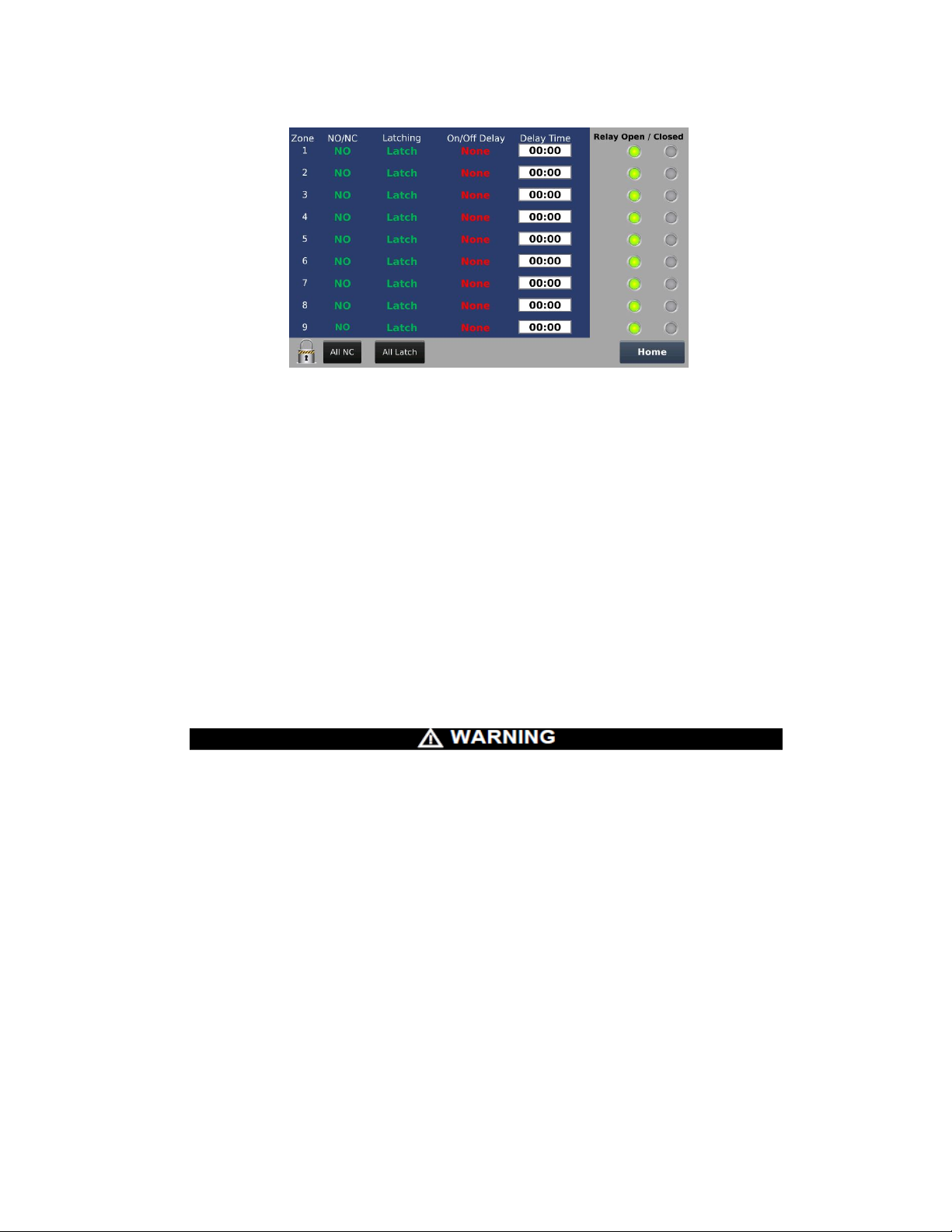
Figure 52. Zone Set points Editor Screen
• If Latch is selected the zone relay contact will remain in the alarmin g state even after
the alarm condition that it is associated with it has cea sed. To change the zone relay
contact back to the non-alarming state the use must press the Unlatch Local Zones
button on the Main Data Screen, see Figure 41. If No Latch is sel ected the zone relay
contact will return to the non-alarming state automaticall y after the alarm condition that
it is associated with has ceased.
• Zone relays can be set to either On Delay or Off Delay onl y if the Latching setting is set
to No Latch.
o On Delay – Zone relay contact will change to the alarm state only when an
associated alarm level is activated, and the set Delay Time has elapsed.
o Off Delay (Typically used for fan control) – Zone relay contact will remain in the
alarming state for the set Delay Time after the associated alarm level has cleared.
NOTE:
o When the Latching setting is set to Latch the On Delay, Off Delay, and Delay Time
are disabled.
• Do not use On Delay for any safety critical function. Us e onl y for Process control.
FAILURE TO FOLLOW THIS WARNI N G CA N RESULT IN SERIOUS PERSONAL
INJURY OR LOSS OF LIFE.
8.6 Network Settings Button:
• Press Network Settings button on the Main Menu screen.
• To modify any settings, verify the password lock/unlock graphic is unlocked.
Review instructions on page 37 to unlock pass word lock/unlock graphic.
• For Ethernet capability, enter IP Address, Subnet M ask and Default Gateway
information.
• Press Date or Time to change settings.
ModCon®75 Touch
54
Page 56

Figure 53. Network & Date/Time Settings
8.7 Active Alarms/Faults Button:
• Press the Active Alarms/Faults button on the Main M enu screen.
• To modify any settings, verify the password lock/unlock graphic is unlocked.
Review instructions on page 38 to unlock password lock/unlock graphic.
• The Active Alarms/Faults screen allows the user to view the following:
o Active Alarms
o Active Faults
o Alarm History
o Fault History
• The Active Alarms/Faults History screen allows the user the save the following to a
Micro SD card.
o Alarm History
o Fault History
• Press the Active Alarms button to change the screen. A nother window will appear
allowing the user to select the Active Alarms, Activ e Faults, Alarm History, and Fault
History as shown in Figure 54.
Figure 54. Active/Fault Screen Selection
55
ModCon®75 Touch
Page 57

• Use the up and down arrows to scroll through and sel ect the desired screen to view.
Press the OK button to change the current screen to the one selected.
• In the Alarm/Fault History screen, the data table can be sav ed to a Micro SD card or
cleared by press the appropriate button as shown in Figure 55
Figure 55. Save/Clear History
• The Active Alarm/Fault History screen will display the following messages when using
a Micro SD card.
o Failed to Write
o No SD Card
o Current Table Written
.
8.8 Password Editor:
• To create a new password press and hold the area indicated in Figure 56 for
approximately 5 seconds until a new window appears, see Figure 57.
• In the new window that appears, touch the Previous Password box. Enter the previous
password (default password is 0 (zero)) from dis played keyboard and press OK. Next,
enter the new password from keyboard and press OK. Finally, press Save to set new
password, see Figure 57.
56
ModCon®75 Touch
Page 58

o
Press
(5Sec)
User can change this password to protect against unauthorized changes.
Here
Figure 56. Password Editor
Figure 57. Enter Password
57
ModCon®75 Touch
Page 59

Chapter 9,
Technical Specifications
Table 5. ModCon75 Touch Specifications
Input Voltage 24VDC
Permissible Voltage Range 22 to 28.8VDC with less than 10% Ripple
Maximum Current Consumption 0.75A @ 24 VDC
LCD Type TFT
Backlight White LED
Resolution 800 x 480 (WVGA)
Back-Up Battery 4 years at 25°C (77°F)
Dimensions Figure 58 thru 60
Environment IP65/66 / Nema 4X (Front Panel)
Operational Temperature -20°C to 55°C (-4°F to 131°F)
Storage Temperature -30°C to 70°C (-22°F to 158°F)
Relative Humidity 5% to 95% (non-condensing)
NOTE:
• See detailed ModCon75 Touch HMI Panel specifications on page 15.
• See detailed ModCon75 Touch CPU Module specif ications on page 20.
• See detailed ModCon75 Touch I/O Module sp ecif ications on page 26.
58
ModCon®75 Touch
Page 60

Dimensions
Figure 58. Dimensions, Front
Figure 59. Dimensions, Side
ModCon®75 Touch
59
Page 61
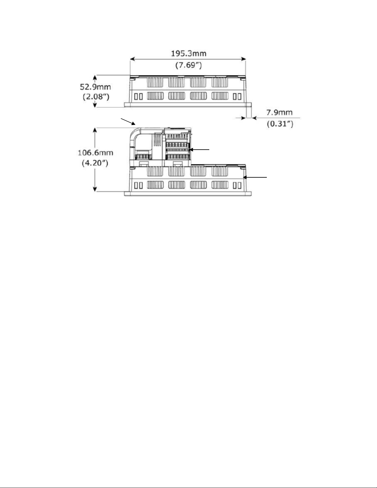
HMI
I/O Module
CPU Module
Figure 60, Dimensions, Top
60
ModCon®75 Touch
Page 62

Appendix A,
Critical Memory Bits
Read Coil function 01 Supported
10
Modbus Comm Failure
261
Sensor 1 Calibration Active
262
Sensor 2 Calibration Active
263
Sensor 3 Calibration Active
670
Zone 1 Alarm
671
Zone 2 Alarm
672
Zone 3 Alarm
673
Zone 4 Alarm
674
Zone 5 Alarm
675
Zone 6 Alarm
676
Zone 7 Alarm
677
Zone 8 Alarm
678
Zone 9 Alarm
Write Coil Function 05 Supported
194
Acknowledge Alarm
Memory Integers
Read Input Register Function 04 Supported
Refer to Table 1 for descriptions
273
Ultima X3 #2 Fault status message
274
Ultima X3 #3 Fault status message
275
Ultima X3 #4 Fault status message
276
Ultima X3 #5 Fault status message
277
Ultima X3 #6 Fault status message
278
Ultima X3 #7 Fault status message
279
Ultima X3 #8 Fault status message
280
Ultima X3 #9 Fault status message
281
Ultima X3 #10 Fault status message
282
Ultima X3 #11 Fault status message
283
Ultima X3 #12 Fault status message
284
Ultima X3 #13 Fault status message
285
Ultima X3 #14 Fault status message
Register Maps
The following register maps are provided for read-only use.
61
ModCon®75 Touch
Page 63

286
Ultima X3 #15 Fault status message
287
Ultima X3 #16 Fault status message
288
Ultima X3 #17 Fault status message
289
Ultima X3 #18 Fault status message
290
Ultima X3 #19 Fault status message
291
Ultima X3 #20 Fault status message
292
Ultima X3 #21 Fault status message
293
Ultima X3 #22 Fault status message
294
Ultima X3 #23 Fault status message
295
Ultima X3 #24 Fault status message
296
Ultima X3 #25 Fault status message
297
Ultima X3 #26 Fault status message
Memory Integers
Read Input Register Function 04 Supported
300
Ultima X3 #2 Gas Value Sensor 1, Left of the Decimal Point
301
Ultima X3 #3 Gas Value Sensor 1, Left of the Decimal Point
302
Ultima X3 #4 Gas Value Sensor 1, Left of the Decimal Point
303
Ultima X3 #5 Gas Value Sensor 1, Left of the Decimal Point
304
Ultima X3 #6 Gas Value Sensor 1, Left of the Decimal Point
305
Ultima X3 #7 Gas Value Sensor 1, Left of the Decimal Point
306
Ultima X3 #8 Gas Value Sensor 1, Left of the Decimal Point
307
Ultima X3 #9 Gas Value Sensor 1, Left of the Decimal Point
308
Ultima X3 #10 Gas Value Sensor 1, Left of the Decimal Point
309
Ultima X3 #11 Gas Value Sensor 1, Left of the Decimal Point
310
Ultima X3 #12 Gas Value Sensor 1, Left of the Decimal Point
311
Ultima X3 #13 Gas Value Sensor 1, Left of the Decimal Point
312
Ultima X3 #14 Gas Value Sensor 1, Left of the Decimal Point
313
Ultima X3 #15 Gas Value Sensor 1, Left of the Decimal Point
314
Ultima X3 #16 Gas Value Sensor 1, Left of the Decimal Point
315
Ultima X3 #17 Gas Value Sensor 1, Left of the Decimal Point
316
Ultima X3 #18 Gas Value Sensor 1, Left of the Decimal Point
317
Ultima X3 #19 Gas Value Sensor 1, Left of the Decimal Point
318
Ultima X3 #20 Gas Value Sensor 1, Left of the Decimal Point
319
Ultima X3 #21 Gas Value Sensor 1, Left of the Decimal Point
320
Ultima X3 #22 Gas Value Sensor 1, Left of the Decimal Point
321
Ultima X3 #23 Gas Value Sensor 1, Left of the Decimal Point
ModCon®75 Touch
62
Page 64

ModCon®75 Touch
322
Ultima X3 #24 Gas Value Sensor 1, Left of the Decimal Point
323
Ultima X3 #25 Gas Value Sensor 1, Left of the Decimal Point
324
Ultima X3 #26 Gas Value Sensor 1, Left of the Decimal Point
325
Ultima X3 #2 Gas Value Sensor 1, Right of the Deci m al P oi nt
326
Ultima X3 #3 Gas Value Sensor 1, Right of the Deci m al P oi nt
327
Ultima X3 #4 Gas Value Sensor 1, Right of the Deci m al P oi nt
328
Ultima X3 #5 Gas Value Sensor 1, Right of the Deci m al P oi nt
329
Ultima X3 #6 Gas Value Sensor 1, Right of the Deci m al P oi nt
330
Ultima X3 #7 Gas Value Sensor 1, Right of the Deci m al Point
331
Ultima X3 #8 Gas Value Sensor 1, Right of the Deci m al P oi nt
332
Ultima X3 #9 Gas Value Sensor 1, Right of the Deci m al P oi nt
333
Ultima X3 #10 Gas Value Sensor 1, Right of the Decimal P oi nt
334
Ultima X3 #11 Gas Value Sensor 1, Right of the Decimal Point
335
Ultima X3 #12 Gas Value Sensor 1, Right of the Decimal P oi nt
336
Ultima X3 #13 Gas Value Sensor 1, Right of the Decimal P oi nt
337
Ultima X3 #14 Gas Value Sensor 1, Right of the Decimal P oi nt
338
Ultima X3 #15 Gas Value Sensor 1, Right of the Decimal Point
339
Ultima X3 #16 Gas Value Sensor 1, Right of the Decimal P oi nt
340
Ultima X3 #17 Gas Value Sensor 1, Right of the Decimal P oi nt
341
Ultima X3 #18 Gas Value Sensor 1, Right of the Decimal P oi nt
342
Ultima X3 #19 Gas Value Sensor 1, Right of the Decimal Point
343
Ultima X3 #20 Gas Value Sensor 1, Right of the Decimal P oi nt
344
Ultima X3 #21 Gas Value Sensor 1, Right of the Decimal P oi nt
345
Ultima X3 #22 Gas Value Sensor 1, Right of the Decimal P oi nt
346
Ultima X3 #23 Gas Value Sensor 1, Right of the Decimal Point
347
Ultima X3 #24 Gas Value Sensor 1, Right of the Decimal P oi nt
348
Ultima X3 #25 Gas Value Sensor 1, Right of the Decimal P oi nt
349
Ultima X3 #26 Gas Value Sensor 1, Right of the Decimal Point
350
Ultima X3 #2 Gas Value Sensor 2, Left of the Decimal Poi nt
351
Ultima X3 #3 Gas Value Sensor 2, Left of the Decimal Poi nt
352
Ultima X3 #4 Gas Value Sensor 2, Left of the Decimal Poi nt
353
Ultima X3 #5 Gas Value Sensor 2, Left of the Decimal P oint
354
Ultima X3 #6 Gas Value Sensor 2, Left of the Decimal Poi nt
355
Ultima X3 #7 Gas Value Sensor 2, Left of the Decimal Poi nt
356
Ultima X3 #8 Gas Value Sensor 2, Left of the Decimal Poi nt
357
Ultima X3 #9 Gas Value Sensor 2, Left of the Decimal Poi nt
63
Page 65

ModCon®75 Touch
358
Ultima X3 #10 Gas Value Sensor 2, Left of the Decimal Point
359
Ultima X3 #11 Gas Value Sensor 2, Left of the Decimal Point
360
Ultima X3 #12 Gas Value Sensor 2, Left of the Decimal Point
361
Ultima X3 #13 Gas Value Sensor 2, Left of the Decim al P oi nt
362
Ultima X3 #14 Gas Value Sensor 2, Left of the Decimal Point
363
Ultima X3 #15 Gas Value Sensor 2, Left of the Decimal Point
364
Ultima X3 #16 Gas Value Sensor 2, Left of the Decimal Point
365
Ultima X3 #17 Gas Value Sensor 2, Left of the Decimal Point
366
Ultima X3 #18 Gas Value Sensor 2, Left of the Decimal Point
367
Ultima X3 #19 Gas Value Sensor 2, Left of the Decimal Point
368
Ultima X3 #20 Gas Value Sensor 2, Left of the Decimal Point
369
Ultima X3 #21 Gas Value Sensor 2, Left of the Decimal Point
370
Ultima X3 #22 Gas Value Sensor 2, Left of the Decimal Point
371
Ultima X3 #23 Gas Value Sensor 2, Left of the Decimal Point
372
Ultima X3 #24 Gas Value Sensor 2, Left of the Decimal Point
373
Ultima X3 #25 Gas Value Sensor 2, Left of the Decimal Point
374
Ultima X3 #26 Gas Value Sensor 2, Left of the Decimal Point
375
Ultima X3 #2 Gas Value Sensor 2, Right of the Deci m al P oi nt
376
Ultima X3 #3 Gas Value Sensor 2, Right of the Decimal Point
377
Ultima X3 #4 Gas Value Sensor 2, Right of the Deci m al P oi nt
378
Ultima X3 #5 Gas Value Sensor 2, Right of the Deci m al P oi nt
379
Ultima X3 #6 Gas Value Sensor 2, Right of the Deci m al P oi nt
380
Ultima X3 #7 Gas Value Sensor 2, Right of the Deci m al Point
381
Ultima X3 #8 Gas Value Sensor 2, Right of the Deci m al P oi nt
382
Ultima X3 #9 Gas Value Sensor 2, Right of the Deci m al P oi nt
383
Ultima X3 #10 Gas Value Sensor 2, Right of the Decimal P oi nt
384
Ultima X3 #11 Gas Value Sensor 2, Right of the Decimal Point
385
Ultima X3 #12 Gas Value Sensor 2, Right of the Decimal P oi nt
386
Ultima X3 #13 Gas Value Sensor 2, Right of the Decimal P oi nt
387
Ultima X3 #14 Gas Value Sensor 2, Right of the Decimal P oi nt
388
Ultima X3 #15 Gas Value Sensor 2, Right of the Decimal Point
389
Ultima X3 #16 Gas Value Sensor 2, Right of the Decimal P oi nt
390
Ultima X3 #17 Gas Value Sensor 2, Right of the Decimal P oi nt
391
Ultima X3 #18 Gas Value Sensor 2, Right of the Decimal P oi nt
392
Ultima X3 #19 Gas Value Sensor 2, Right of the Decimal P oi nt
393
Ultima X3 #20 Gas Value Sensor 2, Right of the Decimal P oi nt
64
Page 66

ModCon®75 Touch
394
Ultima X3 #21 Gas Value Sensor 2, Right of the Decimal P oi nt
395
Ultima X3 #22 Gas Value Sensor 2, Right of the Decimal Point
396
Ultima X3 #23 Gas Value Sensor 2, Right of the Decimal P oi nt
397
Ultima X3 #24 Gas Value Sensor 2, Right of the Decimal P oi nt
398
Ultima X3 #25 Gas Value Sensor 2, Right of the Decimal P oi nt
399
Ultima X3 #26 Gas Value Sensor 2, Right of the Decimal Point
400
Ultima X3 #2 Gas Value Sensor 3, Left of the Decimal Poi nt
401
Ultima X3 #3 Gas Value Sensor 3, Left of the Decimal Poi nt
402
Ultima X3 #4 Gas Value Sensor 3, Left of the Decimal Poi nt
403
Ultima X3 #5 Gas Value Sensor 3, Left of the Decimal Poi nt
404
Ultima X3 #6 Gas Value Sensor 3, Left of the Decimal Poi nt
405
Ultima X3 #7 Gas Value Sensor 3, Left of the Decimal Poi nt
406
Ultima X3 #8 Gas Value Sensor 3, Left of the Decimal Poi nt
407
Ultima X3 #9 Gas Value Sensor 3, Left of the Decimal Poi nt
408
Ultima X3 #10 Gas Value Sensor 3, Left of the Decimal Point
409
Ultima X3 #11 Gas Value Sensor 3, Left of the Decimal Point
410
Ultima X3 #12 Gas Value Sensor 3, Left of the Decimal Point
411
Ultima X3 #13 Gas Value Sensor 3, Left of the Decimal Point
412
Ultima X3 #14 Gas Value Sensor 3, Left of the Decimal Point
413
Ultima X3 #15 Gas Value Sensor 3, Left of the Decimal Point
414
Ultima X3 #16 Gas Value Sensor 3, Left of the Decimal Point
415
Ultima X3 #17 Gas Value Sensor 3, Left of the Decimal Point
416
Ultima X3 #18 Gas Value Sensor 3, Left of the Decimal Point
417
Ultima X3 #19 Gas Value Sensor 3, Left of the Decimal Point
418
Ultima X3 #20 Gas Value Sensor 3, Left of the Decimal Point
419
Ultima X3 #21 Gas Value Sensor 3, Left of the Decimal Point
420
Ultima X3 #22 Gas Value Sensor 3, Left of the Decimal Point
421
Ultima X3 #23 Gas Value Sensor 3, Left of the Decimal Point
422
Ultima X3 #24 Gas Value Sensor 3, Left of the Decimal Point
423
Ultima X3 #25 Gas Value Sensor 3, Left of the Decimal Point
424
Ultima X3 #26 Gas Value Sensor 3, Left of the Decimal Point
425
Ultima X3 #2 Gas Value Sensor 3, Right of the Deci m al P oi nt
426
Ultima X3 #3 Gas Value Sensor 3, Right of the Deci m al Point
427
Ultima X3 #4 Gas Value Sensor 3, Right of the Deci m al P oi nt
428
Ultima X3 #5 Gas Value Sensor 3, Right of the Deci m al P oi nt
429
Ultima X3 #6 Gas Value Sensor 3, Right of the Deci m al P oi nt
65
Page 67

430
Ultima X3 #7 Gas Value Sensor 3, Right of the Deci m al Point
431
Ultima X3 #8 Gas Value Sensor 3, Right of the Deci m al P oi nt
432
Ultima X3 #9 Gas Value Sensor 3, Right of the Deci m al P oi nt
433
Ultima X3 #10 Gas Value Sensor 3, Right of the Decimal P oi nt
434
Ultima X3 #11 Gas Value Sensor 3, Right of the Decimal Point
435
Ultima X3 #12 Gas Value Sensor 3, Right of the Decimal P oi nt
436
Ultima X3 #13 Gas Value Sensor 3, Right of the Decimal P oi nt
437
Ultima X3 #14 Gas Value Sensor 3, Right of the Decimal P oi nt
438
Ultima X3 #15 Gas Value Sensor 3, Right of the Decimal Point
439
Ultima X3 #16 Gas Value Sensor 3, Right of the Decimal P oi nt
440
Ultima X3 #17 Gas Value Sensor 3, Right of the Decimal P oi nt
441
Ultima X3 #18 Gas Value Sensor 3, Right of the Decimal P oi nt
442
Ultima X3 #19 Gas Value Sensor 3, Right of the Decimal P oi nt
443
Ultima X3 #20 Gas Value Sensor 3, Right of the Decimal P oi nt
444
Ultima X3 #21 Gas Value Sensor 3, Right of the Decimal P oi nt
445
Ultima X3 #22 Gas Value Sensor 3, Right of the Decimal Point
446
Ultima X3 #23 Gas Value Sensor 3, Right of the Decimal P oi nt
447
Ultima X3 #24 Gas Value Sensor 3, Right of the Decimal P oi nt
448
Ultima X3 #25 Gas Value Sensor 3, Right of the Decimal P oi nt
449
Ultima X3 #26 Gas Value Sensor 3, Right of the Decimal Point
Memory Integers
Read Input Register Function 04 Supported
Refer to Table 3 for descriptions
450
Ultima X3 #2 Fault Status
451
Ultima X3 #3 Fault Status
452
Ultima X3 #4 Fault Status
453
Ultima X3 #5 Fault Status
454
Ultima X3 #6 Fault Status
455
Ultima X3 #7 Fault Status
456
Ultima X3 #8 Fault Status
457
Ultima X3 #9 Fault Status
458
Ultima X3 #10 Fault Status
459
Ultima X3 #11 Fault Status
460
Ultima X3 #12 Fault Status
461
Ultima X3 #13 Fault Status
462
Ultima X3 #14 Fault Status
ModCon®75 Touch
66
Page 68

463
Ultima X3 #15 Fault Status
464
Ultima X3 #16 Fault Status
465
Ultima X3 #17 Fault Status
466
Ultima X3 #18 Fault Status
467
Ultima X3 #19 Fault Status
468
Ultima X3 #20 Fault Status
469
Ultima X3 #21 Fault Status
470
Ultima X3 #22 Fault Status
471
Ultima X3 #23 Fault Status
472
Ultima X3 #24 Fault Status
473
Ultima X3 #25 Fault Status
474
Ultima X3 #26 Fault Status
Memory Integers
Read Input Register Function 04 Supported
Refer to Table 4 for descriptions
525
Ultima X3 #2 Sensor 1 Current Alarm Status
526
Ultima X3 #3 Sensor 1 Current Alarm Status
527
Ultima X3 #4 Sensor 1 Current Alarm Status
528
Ultima X3 #5 Sensor 1 Current Alarm Status
529
Ultima X3 #6 Sensor 1 Current Alarm Status
530
Ultima X3 #7 Sensor 1 Current Alarm Status
531
Ultima X3 #8 Sensor 1 Current Alarm Status
532
Ultima X3 #9 Sensor 1 Current Alarm Status
533
Ultima X3 #10 Sensor 1 Current Alarm Status
534
Ultima X3 #11 Sensor 1 Current Alarm Status
535
Ultima X3 #12 Sensor 1 Current Alarm Status
536
Ultima X3 #13 Sensor 1 Current Alarm Status
537
Ultima X3 #14 Sensor 1 Current Alarm Status
538
Ultima X3 #15 Sensor 1 Current Alarm Status
539
Ultima X3 #16 Sensor 1 Current Alarm Status
540
Ultima X3 #17 Sensor 1 Current Alarm Status
541
Ultima X3 #18 Sensor 1 Current Alarm Status
542
Ultima X3 #19 Sensor 1 Current Alarm Status
543
Ultima X3 #20 Sensor 1 Current Alarm Status
544
Ultima X3 #21 Sensor 1 Current Alarm Status
545
Ultima X3 #22 Sensor 1 Current Alarm Status
67
ModCon®75 Touch
Page 69

546
Ultima X3 #23 Sensor 1 Current Alarm Status
547
Ultima X3 #24 Sensor 1 Current Alarm Status
548
Ultima X3 #25 Sensor 1 Current Alarm Status
549
Ultima X3 #26 Sensor 1 Current Alarm Status
550
Ultima X3 #2 Sensor 2 Current Alarm Status
551
Ultima X3 #3 Sensor 2 Current Alarm Status
552
Ultima X3 #4 Sensor 2 Current Alarm Status
553
Ultima X3 #5 Sensor 2 Current Alarm Status
554
Ultima X3 #6 Sensor 2 Current Alarm Status
555
Ultima X3 #7 Sensor 2 Current Alarm Status
556
Ultima X3 #8 Sensor 2 Current Alarm Status
557
Ultima X3 #9 Sensor 2 Current Alarm Status
558
Ultima X3 #10 Sensor 2 Current Alarm Status
559
Ultima X3 #11 Sensor 2 Current Alarm Status
560
Ultima X3 #12 Sensor 2 Current Alarm Status
561
Ultima X3 #13 Sensor 2 Current Alarm Status
562
Ultima X3 #14 Sensor 2 Current Alarm Status
563
Ultima X3 #15 Sensor 2 Current Alarm Status
564
Ultima X3 #16 Sensor 2 Current Alarm Status
565
Ultima X3 #17 Sensor 2 Current Alarm Status
566
Ultima X3 #18 Sensor 2 Current Alarm Status
567
Ultima X3 #19 Sensor 2 Current Alarm Status
568
Ultima X3 #20 Sensor 2 Current Alarm Status
569
Ultima X3 #21 Sensor 2 Current Alarm Status
570
Ultima X3 #22 Sensor 2 Current Alarm Status
571
Ultima X3 #23 Sensor 2 Current Alarm Status
572
Ultima X3 #24 Sensor 2 Current Alarm Status
573
Ultima X3 #25 Sensor 2 Current Alarm Status
574
Ultima X3 #26 Sensor 2 Current Alarm Status
575
Ultima X3 #2 Sensor 3 Current Alarm Status
576
Ultima X3 #3 Sensor 3 Current Alarm Status
577
Ultima X3 #4 Sensor 3 Current Alarm Status
578
Ultima X3 #5 Sensor 3 Current Alarm Status
579
Ultima X3 #6 Sensor 3 Current Alarm Status
580
Ultima X3 #7 Sensor 3 Current Alarm Status
581
Ultima X3 #8 Sensor 3 Current Alarm Status
68
ModCon®75 Touch
Page 70

582
Ultima X3 #9 Sensor 3 Current Alarm Status
583
Ultima X3 #10 Sensor 3 Current Alarm Status
584
Ultima X3 #11 Sensor 3 Current Alarm Status
585
Ultima X3 #12 Sensor 3 Current Alarm Status
586
Ultima X3 #13 Sensor 3 Current Alarm Status
587
Ultima X3 #14 Sensor 3 Current Alarm Status
588
Ultima X3 #15 Sensor 3 Current Alarm Status
589
Ultima X3 #16 Sensor 3 Current Alarm Status
590
Ultima X3 #17 Sensor 3 Current Alarm Status
591
Ultima X3 #18 Sensor 3 Current Alarm Status
592
Ultima X3 #19 Sensor 3 Current Alarm Status
593
Ultima X3 #20 Sensor 3 Current Alarm Status
594
Ultima X3 #21 Sensor 3 Current Alarm Status
595
Ultima X3 #22 Sensor 3 Current Alarm Status
596
Ultima X3 #23 Sensor 3 Current Alarm Status
597
Ultima X3 #24 Sensor 3 Current Alarm Status
598
Ultima X3 #25 Sensor 3 Current Alarm Status
599
Ultima X3 #26 Sensor 3 Current Alarm Status
Memory Integers
Read Input Register Function 04 Supported
Refer to Table 2 for description
600
Ultima X3 #2 Fault Status Message
601
Ultima X3 #3 Fault Status Message
602
Ultima X3 #4 Fault Status Message
603
Ultima X3 #5 Fault Status Message
604
Ultima X3 #6 Fault Status Message
605
Ultima X3 #7 Fault Status Message
606
Ultima X3 #8 Fault Status Message
607
Ultima X3 #9 Fault Status Message
608
Ultima X3 #10 Fault Status Message
609
Ultima X3 #11Fault Status Message
610
Ultima X3 #12 Fault Status Message
611
Ultima X3 #13 Fault Status Message
612
Ultima X3 #14 Fault Status Message
613
Ultima X3 #15 Fault Status Message
614
Ultima X3 #16 Fault Status Message
69
ModCon®75 Touch
Page 71

615
Ultima X3 #17 Fault Status Message
616
Ultima X3 #18 Fault Status Message
617
Ultima X3 #19 Fault Status Message
618
Ultima X3 #20 Fault Status Message
619
Ultima X3 #21 Fault Status Message
620
Ultima X3 #22 Fault Status Message
621
Ultima X3 #23 Fault Status Message
622
Ultima X3 #24 Fault Status Message
623
Ultima X3 #25 Fault Status Message
624
Ultima X3 #26 Fault Status Message
Memory Integers
Read Input Register Function 04 Supported
Refer to Table 5 for descriptions
650
Ultima X3 #2 Calibration Status
651
Ultima X3 #3 Calibration Status
652
Ultima X3 #4 Calibration Status
653
Ultima X3 #5 Calibration Status
654
Ultima X3 #6 Calibration Status
655
Ultima X3 #7 Calibration Status
656
Ultima X3 #8 Calibration Status
657
Ultima X3 #9 Calibration Status
658
Ultima X3 #10 Calibration Status
659
Ultima X3 #11 Calibration Status
660
Ultima X3 #12 Calibration Status
661
Ultima X3 #13 Calibration Status
662
Ultima X3 #14 Calibration Status
663
Ultima X3 #15 Calibration Status
664
Ultima X3 #16 Calibration Status
665
Ultima X3 #17 Calibration Status
666
Ultima X3 #18 Calibration Status
667
Ultima X3 #19 Calibration Status
668
Ultima X3 #20 Calibration Status
669
Ultima X3 #21 Calibration Status
670
Ultima X3 #22 Calibration Status
671
Ultima X3 #23 Calibration Status
672
Ultima X3 #24 Calibration Status
70
ModCon®75 Touch
Page 72

673
Ultima X3 #25 Calibration Status
674
Ultima X3 #26 Calibration Status
Bit 0
Fault
Set if True
Bit 1
Sensor 1 Missing
Set if True
Bit 2
Sensor 2 Missing
Set if True
Bit 3
Sensor 3 Missing
Set if True
Bit 4
Sensor 1 Calibration Fault
Set if True
Bit 5
Sensor 2 Calibration Fault
Set if True
Bit 6
Sensor 3 Calibration Fault
Set if True
Bit 7
Sensor 1 Power Fail Fault
Set if True
Bit 8
Sensor 2 Power Fail Fault
Set if True
Bit 9
Sensor 3 Power Fail Fault
Set if True
Bit 10
Power Fault Main Unit +5VDC
Set if True
Bit 11
Sensor 1 End of Life
Set if True
Bit 12
Sensor 2 End of Life
Set if True
Bit 13
Sensor 3 End of Life
Set if True
Bit 14
Configuration Reset
Set if True
Bit 15
Sign
Set if True
Bit 0
Sensor 1 LOC
Set if True
Bit 1
Sensor 2 LOC
Set if True
Bit 2
Sensor 3 LOC
Set if True
Bit 3
Sensor 1 Over Range
Set if True
Bit 4
Sensor 2 Over Range
Set if True
Bit 5
Sensor 3 Over Range
Set if True
Bit 6
Sensor 1 Quick Under Range
Set if True
Table 1
Bit Name Function Description
Table 2
Bit Name Function Description
71
ModCon®75 Touch
Page 73

Bit 7
Sensor 2 Quick Under Range
Set if True
Bit 8
Sensor 3 Quick Under Range
Set if True
Bit 9
Sensor 1 Under Range
Set if True
Bit 10
Sensor 2 Under Range
Set if True
Bit 11
Sensor 3 Under Range
Set if True
Bit 12
Not Used
Bit 13
Not Used
Bit 14
Not Used
Bit 15
Always 1
Bit 0
Device Fault (any fault)
Set for all conditions
Bit 1
Calibration Active - Sensor 1
Set During Calibration
Bit 2
Calibration Active - Sensor 2
Set During Calibration
Bit 3
Calibration Active - Sensor 3
Set During Calibration
Bit 4
Warm Up Mode
Set During Startup
Bit 5
Low Alarm Active
Set While Alarm Relay is Active
Bit 6
Mid Alarm Active
Set While Alarm Relay is Active
Bit 7
High Alarm Active
Set While Alarm Relay is Active
Bit 8
Future
Bit 9
Future
Bit 10
Future
Bit 11
Future
Bit 12
Future
Bit 13
Future
Bit 14
Not Used
Bit 15
Table 3
Bit Name Function Description
72
ModCon®75 Touch
Page 74

Table 4
0 = Normal Operation
1 = Caution
2 = Warming
3 = Alarm
0 = Normal Operation
1 = Sensor 1 In Calibration
2 = Sensor 2 In Calibration
3 = Sensor 3 In Calibration
Table 5
73
ModCon®75 Touch
Page 75

Appendix B,
Optional Remote Relay Modules
• Optional Remote Relay units:
o Five remote relay units may be added to the Modbus network.
o Modbus ID numbers of the remote relay modules must be programmed for ID#30,
31, 32, 33 or 34.
o Relay O0 is the Local Horn relay.
o The Local Horn relay (O0) can only be silenced from the ModCon75 Touch Main
Data Screen Silence button
NOTE:
o If Zone Alarms are programmed as Latch, user can silence the alarm at the
ModCon75 Touch, but the Zone alarm will not clear until the unlatch input is
initiated at the ModCon75 Touch Controller.
Dimensions
.
Figure B-1. Remote Relay Module, Front
Figure B-2. Remote Relay Mod u l e, Side
ModCon®75 Touch
74
Page 76

Power Supply
Input voltage
24VDC
Permissible range
20.4VDC to 28.8VDC with less than 10% ripple
Max. current consumption
93mA @ 24VDC
Relay Outputs
Number of outputs
6 relays (5 in use)
Output type
SPST-NO (form A)
Isolation
By relay
Type of relay
Fujitsu, JY-24H-K or compatible
Output current
5A maximum (resistive load)
Rated voltage
250VAC / 30VDC
Minimum load
10mA, 5VDC
Response time
10ms (typical)
Contact protection
External precautions required (Figure 51, pg. 53)
Graphic Display Screen
LCD Type
STN, LCD display
Illumination backlight
White LED
Display resolution
128x64 pixels
Viewing area
2.4”
Colors
Monochrome
Screen Contrast
Via software
Screen brightness control
Via software
Communication Ports
Port 1
1 channel, RS232/RS485
Galvanic isolation
No
Baud rate
19200 bps
RS232
Input voltage
20VDC absolute maximum
Cable length
15m maximum (50 ft.)
RS485 Input voltage
-7 to +12VDC differential maximum
Cable type
Shielded twisted pair, in compliance with EIA 485
Cable length
1200m maximum (3937 ft.)
Table B-1. Remote Relay Module Specifications
75
ModCon®75 Touch
Page 77

Nodes
Up to 5
Battery Back-up
RTC and system data including variable data.
Battery replacement
Coin type 3V, lithium battery, CR2450
Clock
Real Time Clock (RTC)
Real time clock functions (date and time)
Environment
Operational temperature
0 to 50°C (32 to 122°F)
Storage temperature
-20 to 60°C (-4 to 140°F)
Relative Humidity (RH)
10% to 95% (non-condensing)
DIN-rail mounted (IP20/NEMA 1)
Operating Altitude
2000m (6562 ft.)
Shock
IEC 60068-2-27, 15G, 11ms duration
amplitude, 8.4Hz to 150Hz, 1G acceleration
Battery life 7 year typical 25°C (77°F), battery back-up for
Mounting method Panel mounted (IP65/66/ NE MA 4X)
Vibration IEC 600068-2-6, 5Hz to 8.4Hz, 3.5mm constant
Jumper Settings
• Table B-2 and Figure B-3 indicates how to set a specific jumper to change input
functionality.
• Table B-3 and Figure B-4 indicates how to set a specific jumper to change
communication functionality.
• To open the controller and access the jumpers, see Figures B-3 and B-4.
• Incompatible jumper settings and wiring connections may seriously damage
the controller.
FAILURE TO FOLLOW THIS WA RNING CAN RESULT IN SERIOUS PERSONAL
INJURY OR LOSS OF LIFE.
76
ModCon®75 Touch
Page 78

Digital Inputs
JP1
npn (sink)
A
pnp (source)
B*
Inputs, Digital or Analog
JP5
JP6
Digital
A A Analog
B*
B*
Analog Inputs
JP3
JP4
Voltage
A A Current
B*
B*
*Default Settings
Table B-2. Remote Relay I/O Input Jumper Setti ngs
Figure B-3. Input Jumpers
77
ModCon®75 Touch
Page 79

TERM
OFF
ON*
COMM
232
485*
*Default Settings
Table B-3. Communication Port
Figure B-4. Communication Port Jumpers
Figure B-5. RS485 Pin Layout
• **When a port is adapted to RS485, Pin 1 (DTR) is used for signal A, and Pin 6 (DSR)
signal is used for signal B.
ModCon®75 Touch
78
Page 80

Opening the Remote Relay Module
• Disconnect system power before connecting or disconnecting any modules or
devices.
• Components in this module are electrostatic discharge sensitive (ESDS). Use proper
personal grounding procedures when removing, handling or adjusting the electronic
module.
• Avoid touching the printed circuit board directly. Hold the printed circuit board by its
connectors.
FAILURE TO FOLLOW THESE WARNINGS CAN RESULT IN SERIOUS PERSONAL
INJURY OR LOSS OF LIFE.
1. Turn off the power supply, disconnect, and dism ount the remote relay module.
2. The back cover of the remote relay module comprises 4 screws, located in the corners.
Remove the screws and pull off the back cover.
Changing the IO Jumper Settings
1. The I/O board of the remote relay is now exposed, enabling you to change I/O settings
according to jumpers shown in Table B-2.
Changing Communication Jumper Settings
1. To access the communication jumpers, locate t he screw close to COM port 1 (see
Figure B-6) and remove it.
2. Hold the I/O printed circuit board by its top, bottom connectors, and steadily pull the
board off as shown in Figure B-7.
3. Locate and then change the jumpers as required, see Figure B-3.
ModCon®75 Touch
79
Page 81

Remove
Screw
COM Port 1
Figure B-6. Remote I/O Printed Circuit Board
Figure B-7. Remote I/O Printed Circuit Board Removal
80
ModCon®75 Touch
Page 82

Closing the Remote Relay Module
1. Gently replace the board. Make certain that the pi ns correctly into their matching
receptacle. Do not force the board into place, see Figure B-7. Doing so may damage
the remote relay module.
2. Replace the back cover of the remote relay module and fasten the corner screws.
Figure B-7. Closing the Remote Relay
Remote Relay Module Mounting
Panel Mounting
Note:
o The mounting panel cannot be more than 5 mm thick.
1. Make a panel cutout measuring 92x92 mm (3.622”x3.622”).
2. Slide the remote relay module into the cutout, ensu ring that the rubber seal is in place.
3. Push the 2 mounting brackets into their slots on the si des of the remote relay module
as shown in Figure B-8.
4. Tighten the bracket screws against the panel. Hold t he bracket securely against the
unit while tightening the screw.
5. When properly mounted, the remote relay module is squarely situated in the panel
cutout as shown in Figure B-9.
ModCon®75 Touch
81
Page 83

Figure B-8. Remote Relay Panel Mounting
Figure B-9. Remote Relay Panel Mounted
ModCon®75 Touch
82
Page 84

DIN-rail Mounting
1. Snap the remote relay module onto the DIN rail as shown in F igure B-10.
2. When properly mounted, the remote relay module is squarely situated on the DIN-rail
as shown in Figure B-11.
Figure B-10. Remote Relay DIN-Rail Mounting
Figure B-11. Remote Relay Mounted
ModCon®75 Touch
83
 Loading...