

Page 1
MSA Latchways Freestanding Constant Force
Design Centre: Latchways plc
Hopton Park, Devizes, SN10 2JP
Document No; 65640-98./Issue No. 6
1
MSAsafety.com
65643-00
65640-00
65644-00
Technical Datasheet
®
post
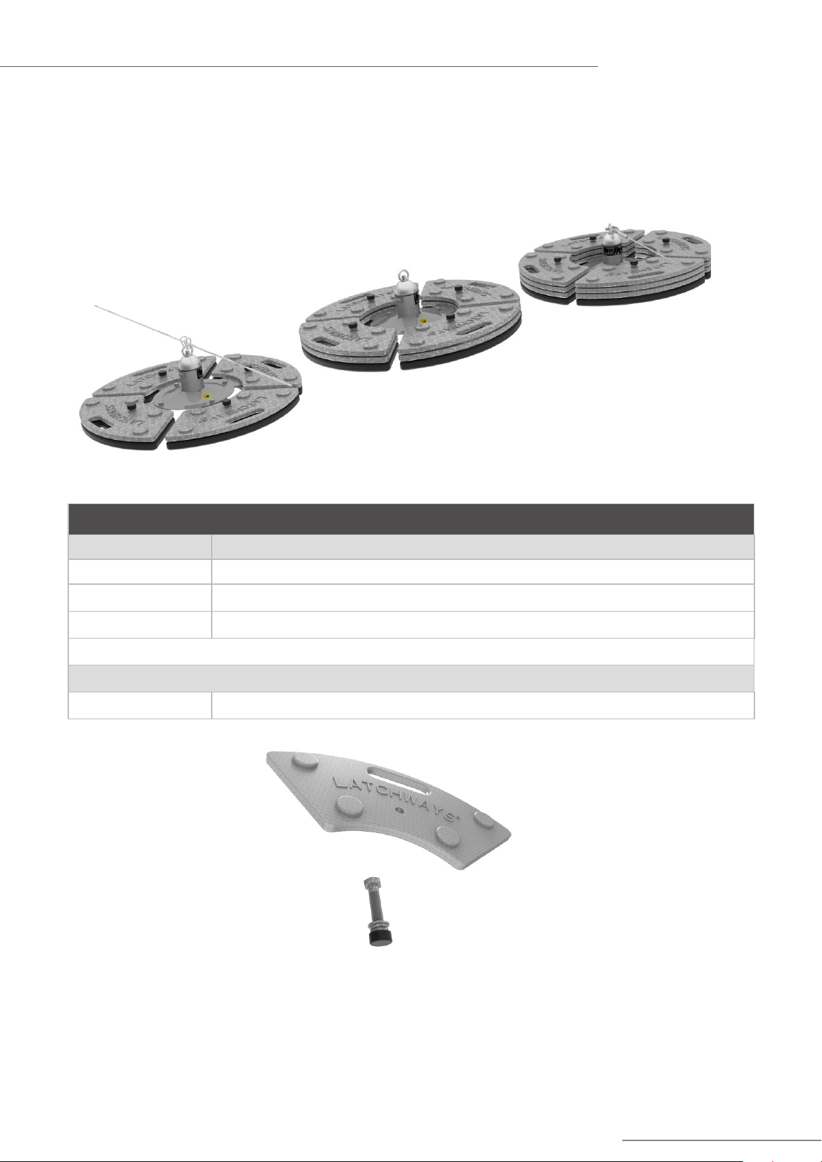
MSA Latchways Freestanding Constant Force post range
Part Number Model name/Model description
65640-00 300 kg Single point anchor for the attachment of one user
65643-00 200 kg intermediate anchor for use as part of a Type C horizontal lifeline
65644-00 400 kg End or corner anchor for use as part of a Type C horizontal lifeline
1
2
Must purchase articulating D-ring assembly pn#85032-00 to complete kit purchase for single point anchor use.
Upgrade kit
65641-00 100 kg Upgrade kit (Upgrade 65640-00 to 65644-00)
Upgrade kit contents
4 x 25 kg weight segment
4 x Nut, bolt, washers & end cap assembly
1
. This Anchor must not be used as a Type A single point anchor.
2
. This anchor may also be used as a Type A single point anchor for the attachment of one user.
Page 2
MSA Latchways Freestanding Constant Force
Design Centre: Latchways plc
Hopton Park, Devizes, SN10 2JP
Document No; 65640-98./Issue No. 6
2
MSAsafety.com
Base Plate
Aluminium, Powder Coated
Insulating Ring
30% Glass Filled Nylon 66
Tube
Aluminium, Thickness, Powder Coated
Dome
316s Stainless Steel, Electro-polished
Coil assembly
316s Stainless Steel
Spreader Plate
316s stainless steel
Nuts & Bolts
Marine Grade A4 Stainless Steel
Static Weight Anchor
Segments
Grey Iron, Hot Dip Galvanized, 85m
Cross straps
6mm Thick Steel Plate, Hot Dip Galvanized, 85m
Bolts, Nuts And Washers
Galvanized
Rubber Coating
Natural Rubber, UV Additives
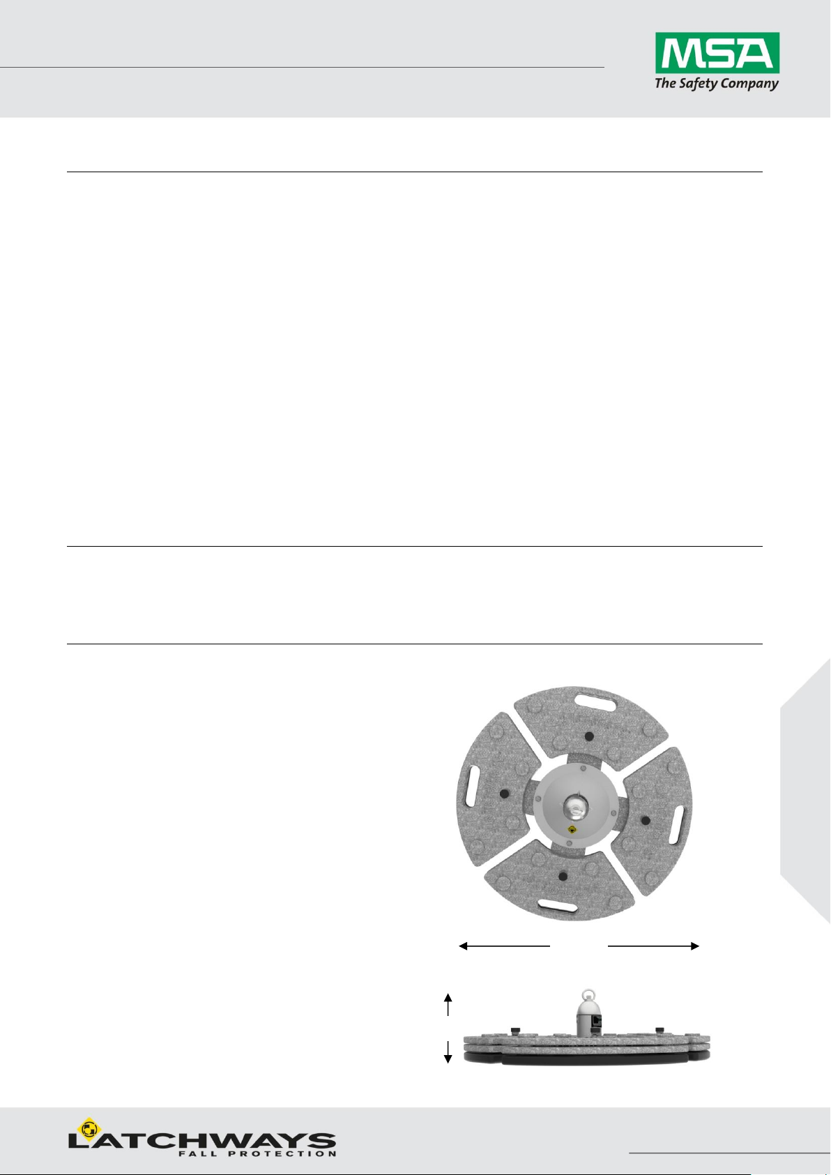
0.3 m
Ø1.0m
Technical Datasheet
Materials
Constant Force Post
®
post
Loadings
Initial yield force 2.7 kN.
Continuous deployment force 10 kN.
Quality control
100% visual inspection on all critical items
100% Inspection Gauging
100% Visual Inspection Of Sub And Final Assemblies
Batch Conformance Tested To Ultimate Strength
Page 3

MSA Latchways Freestanding Constant Force
Design Centre: Latchways plc
Hopton Park, Devizes, SN10 2JP
Document No; 65640-98./Issue No. 6
3
MSAsafety.com
Part number(Weight)
Rubber coated
weights
Galvanised weights
65640-00 (300 kg)
4
8
65643-00 (200 kg)
4
4
65644-00 (400 kg)
4
12
Revision notes
Date
Rev
CR No.
Comments
02-11-16
6
100058
Clarified the defined maximum user status of the different Anchor variants
Karabiner
Snap hook
®
post
Technical Datasheet
Notes
1. The total weight combinations for the anchor devices are;
2. The anchor device is for use where it is impractical to install constant force posts or rigid anchor posts to the
roof or supporting structure below.
3. The anchor device is for use on nominally flat roofs up to a maximum pitch of 5.
4. For situations where the arrest of a fall causes the anchor to move up a slope the maximum pitch of the roof
is 15.
5. The anchor device is supplied with four rubber coated base weights. These must be in contact with the roof
surface when it is fully assembled.
6. When used as part of a Type C horizontal lifeline system the maximum number of users connected to the
system must not exceed two (2).
7. When used as part of a Type C horizontal lifeline system, the maximum intermediate spacing between the
anchor devices is 10 m.
8. When connecting to the cable system always use a full body harness and energy absorbing lanyard to
appropriate national standards.
9. The anchor device must never be used during period when frost, ice or snow are present on the roof surface.
10. The anchor device must never be used if the roof surface is contaminated by grease, oil or any other type of
lubricant.
11. Refer to installation and user instructions 65642_99 for further information for use as an end anchor.
When used as a Type A single point anchor and a karabiner type connector is to be attached to the D-ring,
use D-ring 85030-00 or 85032-00
When used as a Type A single point anchor and a snap hook type connector is to be attached to the D-ring,
use D-ring 85032-00 this will avoid the connector from becoming unintentionally detached which is referred
to as ‘roll-out’
 Loading...