

Page 1
FlameGard® 5
Test Lam
p
The information and technical data disclosed in
this document may be used and disseminated
only for the purposes and to the extent
specifically authorized in writing by MSA.
Instruction Manual
MSA reserves the right to change published
specifications and designs without prior notice.
Part No. MAN5TL-EU
Revision 0
Page 2

ii
FlameGard 5 Test Lamp
EC Declaration of Conformity
MANUFACTURED BY: Mine Safety Appliances Company
1000 Cranberry Woods Drive
Cranberry Township, PA 16066 USA
The manufacturer or the European Authorized Representative
MSA AUER GmbH , Thiemannstraße 1 , D-12059 Berlin
declares that the product : FlameGard 5 Test Lamp
based on the EC-Type Examination Certificate :
Sira 10 ATEX1364
complies with the ATEX directive 94/9/EC, Annex III. Quality Assurance
Notification complying with Annex IV of the ATEX Directive 94/9/EC has been
issued by SIRA Certification Service, Notified Body number: 0518.
The product is in conformance with the directive 2004 / 108/ EC ,(EMC) :
EN 50130-4 : 2002 EN 61000 - 6 - 4 :2007
MSA AUER GmbH
Dr. Axel Schubert
R & D Instruments Berlin , March 2011
Page 3

iii
FlameGard 5 Test Lamp
Warning: Do not leave battery uncharged. It will result in permanent battery damage
Table of Contents
Format Conventions.................................................................................................................. iv
Notes, Cautions, and Warnings ................................................................................................ iv
Contacting Customer Support...................................................................................................iv
1.0 INTRODUCTION ...................................................................................................................... 5
1.1 Notice .........................................................................................................................................5
1.2 Special Warnings .......................................................................................................................5
1.3 Description .................................................................................................................................5
1.4 Upon Receiving..........................................................................................................................5
1.5 Test Lamp Operating Principle ..................................................................................................7
2.0 QUICK START GUIDE ............................................................................................................. 8
3.0 TEST LAMP COMPONENTS .................................................................................................. 9
3.1 Lamp Housing Assembly ...........................................................................................................9
3.2 Microcontroller............................................................................................................................9
3.3 Rotary Switch Setting.................................................................................................................9
3.4 Rechargeable Battery ................................................................................................................9
3.5 Power Jack.................................................................................................................................9
3.6 Push Button..............................................................................................................................10
3.7 Aluminum Case and Cap .........................................................................................................10
3.8 Battery Charge State Indicator.................................................................................................10
4.0 USE AND OPERATION ......................................................................................................... 11
5.0 TEST LAMP MAINTENANCE AND WARRANTY ................................................................ 14
5.1 Maintenance.............................................................................................................................14
5.2 Cleaning the Sapphire Window................................................................................................14
5.3 Recharging the Battery ............................................................................................................15
5.4 Obtaining Service.....................................................................................................................15
5.5 Warranty..................................................................................................................................15
6.0 TROUBLESHOOTING GUIDE............................................................................................... 17
7.0 CUSTOMER SUPPORT......................................................................................................... 18
7.1 MSA Office ......................................................................... Fehler! Textmarke nicht definiert.
7.2 Other Sources for Help ............................................................................................................18
8.0 APPENDIX.............................................................................................................................. 19
8.1 Specifications ...........................................................................................................................19
8.1.2 Regulatory Agencies ...................................................................................................19
8.1.3 Classification Area and Protection Methods ...............................................................20
Page 4
iv
FlameGard 5 Test Lamp
About This Manual
This manual provides instructions for operating, and maintaining the MSA FlameGard 5 Test
Lamp. The intended audience includes installation personnel, field service technicians, and
other technical staff involved in using the Test Lamp.
Format Conventions
Several format conventions are used throughout this manual for Notes, Cautions, and
Warnings. These conventions are described below.
Notes, Cautions, and Warnings
NOTE: Notes provide supplementary details such as exception conditions, alternate methods
for a task, time saving tips, and references to related information.
CAUTION: These notices describe precautions to prevent hazardous conditions that may
damage the equipment.
WARNING: These notices describe precautions to prevent hazardous conditions that may
cause injury to people working with the equipment.
Contacting Customer Support
For additional product information not contained in this manual, please contact MSA Customer
Support. Refer to Section 7.0 for contact information.
Page 5
5
FlameGard 5 Test Lamp
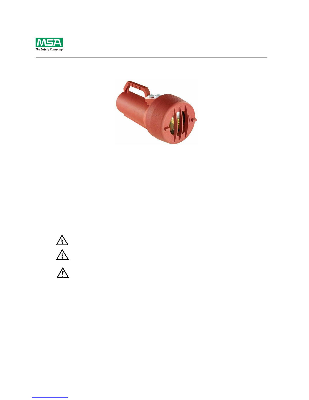
1.0 Introduction
Figure 1: FlameGard 5 Test Lamp
1.1 Notice
All information contained in this instruction manual applies only to the setup and operation of
the FlameGard 5 Test Lamp with flame detectors provided by MSA. The sale of the test lamp
does not license the user to reproduce MSA drawings or to utilize any information contained in
this manual without prior written permission.
The FlameGard 5 Test Lamp is easy to set up and operate. However, this manual should be
read in full, and the information contained herein understood, before attempting to operate the
test lamp in service.
1.2 Special Warnings
Warning: Do not leave battery uncharged. It will result in permanent battery damage.
WARNING: UV light is injurious to one’s vision. Do not stare into functioning lamp. Wear eye
protection of UV blocking glasses to prevent eye injury.
CAUTION: Do not attempt to recharge the FlameGard 5 Test Lamp in areas where
combustible gases or potential explosive gases are located.
1.3 Description
The FlameGard 5 Test Lamp is a battery operated rechargeable test lamp specifically designed
to test MSA’s UV/IR and Multi-Spectral IR Flame Detectors. The test lamp provides a highenergy, broadband radiation source that emits sufficient energy in both the ultraviolet and
infrared spectra to activate UV and/or IR detectors. To simulate the flickering of a fire, the test
lamp automatically flashes at various selectable rates.
1.4 Upon Receiving
FlameGard 5 Test Lamp leaves the factory with the battery disconnected. The customer must
connect and fully charge the battery before use. If you connect the battery and activate the
Page 6

6
FlameGard 5 Test Lamp
push button, the RED LED will stay on for 60 seconds. It will continue to do so until the battery
has been fully charged.
Since the FlameGard 5 Test Lamp goes to fault mode when a charger is plugging in and no
battery is present, you must plug in the battery before the charger.
Make sure to keep the lens and the reflector is kept clean from debris and fingerprints. Grease
on the window will absorb the required energy from reaching the flame detector.
Please follow the steps outlined below to connect the battery:
• Loosen the Set Screw on the Cap.
• Unscrew the Cap counterclockwise and remove it from the Body.
• Remove the two screws holding Reflector on the Body.
• Pull the Reflector off to reveal a 4-Pin Connector on the PC Board.
• Plug the 4 wire Connector coming from the Body into the 4 -Pin Connector on the PC
board. The pins on the connector align one way only.
• Reposition the Reflector on the Body and tighten 2 screws to hold the Reflector on the
Body.
• Reinstall the Cap to the FlameGard 5 Test Lamp Body by screwing it on clockwise.
• Tighten the Set Screw on the Cap.
• Follow Section 5.3 in this Instruction Manual to recharge the battery.
Page 7

7
FlameGard 5 Test Lamp
1 FlameGard 5 Test Lamp body 6 Cap
2 Piezo ON/OFF switch 7 Set screw
3 Charging plug cover 8 Refllector
4 PC board 9 4-pin battery connector
5 Reflector mounting screw
Figure 2: FlameGard 5 Test Lamp Battery Connection
1.5 Test Lamp Operating Principle
A variety of flashing test patterns, selectable through a rotary switch, allows the FlameGard 5
Test Lamp to check the operation of MSA flame detectors. When the specific flashing pattern
for a given type of flame detector is appropriately selected, the test lamp triggers the alarm or
test mode. Please refer to Table 2 for rotary switch settings.
Page 8

8
FlameGard 5 Test Lamp
2.0 Quick Start Guide
Figure 3: Approximate Distance between a FlameGard 5 Test Lamp and a Flame Detector
It is important to begin a series of flame detector checks with a fully charged Test Lamp.
• Stand between 3 and 12 m from a Flame Detector that is to be tested and aim the Test
Lamp directly into the detector window
• Press the ON button and be sure the high intensity pulsing beam strikes the detector
face squarely.
• On some Flame Detectors shaking the lamp from side to side or up and down may
increase the simulation of flame flicker and improve the response of the flame detector
to the lamp.
• When the Flame Detector senses the Test Lamp, the red LED will blink slowly. The
green light may also blink. After a time delay the red LED will start to blink quickly.
This signifies the completion of the test.
NOTE: Please refer to Table 2 for maximum distance to each detector.
NOTE: The FlameGard 5 Test Lamp triggers a Flame Detector into alarm. The system must
be disabled during test if you do not want false trips.
To conserve charge, do not operate the test lamp longer than is necessary to test a Flame
Detector.
When the battery level drops below the level required to maintain the proper intensity of the
lamp, an internal low voltage circuit will shut the lamp off until the battery has been recharged.
Please refer to Section 5.3 for complete recharging instructions.
It is mandatory that the FlameGard 5 Test Lamp be kept on charge when not in use to prevent
excessive battery discharge. The batteries may be charged an average of 500 times before the
battery pack is replaced.
NOTE: Please refer to Section 3.8 for Battery Charge State Indicator details.
NOTE: Please refer to Section 5.3 for detailed information on Recharging the Battery. The
normal recharge time for the rechargeable battery is 3.5 hours.
Page 9

9
FlameGard 5 Test Lamp
3.0 Test Lamp Components
3.1 Lamp Housing Assembly
NOTE: Do not put fingerprints on the reflector or the light bulb, as this will reduce the available
radiation required by the individual detector.
The lamp housing assembly consists of a gold-plated parabolic reflector with the lamp affixed to
its center. A light emitting diode (LED) that serves as a battery charge indicator is also housed
near the edge of the reflector.
3.2 Microcontroller
The FlameGard 5 Test Lamp’s flashing patterns are controlled by a microcontroller. This device
also monitors battery voltage and shuts down the flash lamp output when the battery charge is
low. The microcontroller resides on the functional board.
3.3 Rotary Switch Setting
A rotary switch is used to configure the test lamp to function with FlameGard 5 UV/IR and MSIR
Detectors. Positions of the rotary switch for each of these detectors are noted in Table 2 and
are labeled next to the rotary switch inside the lamp. The rotary switch resides on the functional
board
. (Do not operate the Test Lamp in factory mode. Damage may result to the Test Lamp)
3.4 Rechargeable Battery
The FlameGard 5 Test Lamp is powered by a 12V rechargeable battery. It is mandatory to
keep the test lamp docked with its battery charger when the test lamp is not being used. This
will increase the expected life of the battery and will always keep the test lamp available for
immediate use.
Warning: Do not leave battery uncharged. It will result in permanent battery damage.
NOTE: The normal recharge time for the rechargeable battery is 3.5 hours.
3.5 Power Jack
The power jack is located directly under the aluminum cap and can be accessed when the cap
is removed. The cap must always be in place when operated in a hazardous location. An Allen
wrench is included with the test lamp to unscrew or affix the plug. With the plug removed, the
battery can be recharged by connecting the jack to the FlameGard 5 Test Lamp battery
charger. The battery charger operates from a 110 – 240 VAC power line.
Page 10

10
FlameGard 5 Test Lamp
3.6 Push Button
The push button toggles the lamp ON or OFF. Press the button once to turn the lamp on, and
press it again to turn the instrument off. After flashing for a maximum of 5 minutes, the test
lamp will turn itself off. This is to prevent the battery becoming completely discharged if the
ON / OFF button is accidentally bumped on.
3.7 Aluminum Case and Cap
The FlameGard 5 Test Lamp red aluminum housing is explosion proof for use in hazardous
locations (8.1.3). It can also be used for general-purpose, non-hazardous applications.
3.8 Battery Charge State Indicator
The tri-color LED affixed to the gold parabolic reflector displays the charge state of the battery.
The flashing patterns and colors of the signals are shown in Table 1.
Battery Charge LED Color and Flashing Pattern
Fully charged
Solid green
Charging
Solid yellow
Charging paused
Blinking yellow. This occurs if the battery is too hot (> 60°C)
Fault
Blink red once per second
Discharged
Solid red for one minute after the push button is pressed, then off
Never charged &
switch pushed
Solid red for one minute after the push button is pressed, then off
Battery not connected
Solid red for one minute after the push button is pressed, then off
Wrong charger
connected
Solid red for one minute after the push button is pressed, then off
Table 1: Charge State Indicator
NOTE: The FlameGard 5 Test Lamp attempts to detect improper chargers. However it can not
detect all improper chargers, care must be used to ensure the proper charger is used.
If the improper charger is used, disconnect the charger and wait 1 minute until the red LED goes
out before connecting the proper charger.
Page 11

11
FlameGard 5 Test Lamp
4.0 Use and Operation
Figure 4: Reflector Mounting in Body
1 Set screw (lock) 4 Corresponding holes on FlameGard 5 Test lamp
body
2 Cap assy 5 Charging plug
3 Mounting screws on reflector 6 Piezo ON/OFF switch
Page 12

12
FlameGard 5 Test Lamp
Prior to opening of the test lamp make sure that the set screw located on the cap is loosened
sufficiently to remove the cap.
When closing, make sure that the captive screws (located on the reflector) are matched with
the holes located on the body of the test lamp.
Before beginning a flame detector check, adjust the rotary switch setting in the FlameGard 5
Test Lamp according to the type of MSA flame detector used. Table 2 shows the rotary switch
configurations for MSA flame detectors FlameGard 5 MSIR and FlameGard 5 UV/IR. Using a
fully charged FlameGard 5 Test Lamp, stand up to the distance specified in Table 2 from the
flame detector to be tested and aim the FlameGard 5 Test Lamp 5 directly into the detector
window. Press the ON button and ensure the high intensity intermittent beam strikes the
detector face. If the system is operating normally, the instrument will go into a warning condition
after a few flashes of the test lamp. If the lamp remains on for the period set by the time delay
adjustment, the Flame Detector will go into alarm
1
.
NOTE: Before testing any MSA flame detector, see Table 2 and Figure 5 to ensure the rotary
switch setting is correct for the particular detector.
CAUTION: When operating in conditions involving fog, rain or frost, UV and IR radiation are
(diminished) with increasing levels of moisture. The moisture level will affect the
potential range of the detector. When using the test lamp in conditions of frost,
make sure that the lens is free of frost and ice. A plastic card can be used without
scratching the lens cap to remove frost build-up.
NOTE: Recharging the battery and normal docking of the test lamp when not in use is
mandatory. This will extend the useful life of the battery and also make the test lamp
available for immediate use. Normal recharge time is approximately 3 hours; the
maximum recharge time is 3.5 hours.
1
For test initiation with the FlameGard 5 MSIR Flame Detector, please refer to the FlameGard 5 MSIR Flame
Detector Instruction Manual.
Page 13

13
FlameGard 5 Test Lamp
Figure 5: Location of Functional Board under Lamp Assembly
NOTE: Location of the rotary switch in the FlameGard 5 MSIR Flame Detector control board,
shown in Figure 5.
Detector Test Mode Initiation or Detector Alarm Trigger with FlameGard 5 Test Lamp
Flame Detector
to Test
Rotary Switch
Setting
Maximum Distance
to Detector (ft)
Results
FlameGard 5
UV/IR
20 [6 m]
FlameGard 5 UV/IR triggers into
alarm mode
FlameGard 5
UV/IR-E
20 [6 m]
FlameGard 5 UV/IR-E triggers into
alarm mode
FlameGard 5
MSIR
35 (High Sensitivity)
[11 m]
FlameGard 5 MSIR enters test
mode
FlameGard 5
MSIR
18 (Medium
Sensitivity)
[5.5 m]
FlameGard 5 MSIR enters test
mode
FlameGard 5
MSIR
8 (Low Sensitivity)
[2.5 m]
FlameGard 5 MSIR enters test
mode
Table 2: Detector Test Mode Initiation or/Detector Alarm Trigger with FlameGard 5 Test Lamp
Rotary Switch
shown in position 1
(for testing
FlameGard UV/IR
Flame Detectors)
FlameGard
Rotary Switch Configurations
SWI
FLAMEGARD DETECTOR
0 FACTORY
1 UV/IR
2
3
4 MSIR
Page 14

14
FlameGard 5 Test Lamp
5.0 Test Lamp Maintenance and Warranty
5.1 Maintenance
Routine maintenance for the test lamp is minimal:
• When the test lamp is not being used, it is mandatory
to ensure that the test lamp
is docked on the charger and the charger is connected to a live 110 – 240VAC
power supply adapter. Permanent battery damage will occur if not charged for 60
days.
• Make sure that the test lamp lens is free of frost or large accumulations of moisture
during frosty conditions or inclement weather.
• The battery life will be affected by extreme temperatures. Store and charge the
battery between +5°C and +30°C (+41°F and 86°F) if possible.
There are no user serviceable parts inside the test lamp. After a number of years, the battery
may fail. This will be indicated by a flashing red indicator at the front of the lamp. The unit
should be returned to MSA for a replacement battery. If the test lamp is to be discarded, the
battery must be recycled at this point.
In most countries it is illegal to dispose of the battery with other garbage. MSA has a Recycle
Program in place to recycle the used batteries.
NOTE: The removal of particulate matter and any film buildup on the Sapphire Window is
necessary to ensure proper sensitivity of the system. It is recommended that the
window be cleaned at least every 30 days if the detector is located in a particularly dirty
environment.
5.2 Cleaning the Sapphire Window
A clean, soft, lint-free cloth, tissue or cotton swab should be used to apply the cleaning solution.
The window is not glass; it is made from sapphire. The cleaning solution should be Industrial
Strength Windex
®
with Ammonia D.
Do not touch the window with fingers.
1. Wet the window with the solution.
2. Rub with a dry, unsoiled cloth until the window is clean.
3. Completely dry the window.
CAUTION: Do not use a commercial glass cleaner other than Industrial Strength Windex
®
with
Ammonia D.
Page 15

15
FlameGard 5 Test Lamp
5.3 Recharging the Battery
Before the lamp is used for the first time, or after it has been used to the point where the red
LED at the front has come on solidly, the battery must be recharged. To recharge the battery,
take the test lamp to a non-hazardous area where there is no possibility of an explosive gas or
dust atmosphere being present. The temperature in this area must be between 32°F (0°C) and
104°F (40°C). No damage will occur if the unit is outside the temperature range, but the battery
will not charge.
Use an Allen wrench to remove the charging plug stopper and connect the MSA Switching
Power Supply to the charging socket exposed by removing the charging stopper.
Plug the Switching Power Supply into an electrical outlet between 100 and 240 VAC 50 to
60 Hz rated to provide at least 1.5 A. The charge indicator LED at the front of the test lamp will
change to the color yellow to show that the battery lamp is charging. When the charge is
complete (less than 3.5 hours), the charge indicator will change to green. If the lamp is to be
stored, leave it connected to the Switching Power Supply to keep the battery charged.
Before using the test lamp, unplug the charging connector from the test lamp, carefully insert
the charging plug stopper using an Allen wrench and screw it all the way into the hole. Do not
over-tighten the stopping plug. The lamp can now be safely used in hazardous locations as
specified on the test lamp nameplate and in Section 8.1.3 of this manual.
5.4 Obtaining Service
The FlameGard 5 Test Lamp contains no user serviceable parts. To obtain information
regarding factory service, contact MSA or your MSA representative. Please have the following
information available:
• Instrument model number (on the nameplate)
• Instrument serial number (on the nameplate)
• Description of the problem
5.5 Warranty
Caution: There are no user serviceable parts inside the FlameGard 5 Test Lamp. Work
performed by persons not authorized by MSA will void the warranty.
MSA warrants the FlameGard 5 Test Lamp and the accessory battery charger to be free from
defects in workmanship or material under normal use and service within two (2) years from the
date of shipment.
MSA will repair or replace without charge any equipment found to be defective during the
warranty period. Full determination of the nature of, and responsibility for, defective or
damaged equipment will be made by MSA personnel.
Defective or damaged equipment must be shipped prepaid to MSA or the representative from
which shipment was made. In all cases, this warranty is limited to the cost of the equipment
Page 16

16
FlameGard 5 Test Lamp
supplied by MSA. The customer will assume all liability for the misuse of this equipment by its
employees or other personnel.
All warranties are contingent upon proper use in the application for which the product was
intended and do not cover products which have been modified or repaired without MSA
approval or which have been subjected to neglect, accident, improper installation or application,
or on which the original identification marks have been removed or altered.
EXCEPT FOR THE EXPRESS WARRANTY STATED ABOVE, MSA DISCLAIMS ALL
WARRANTIES WITH REGARD TO THE PRODUCTS SOLD, INCLUDING ALL IMPLIED
WARRANTIES OF MERCHANTABILITY AND FITNESS AND THE EXPRESS WARRANTIES
STATED HEREIN ARE IN LIEU OF ALL OBLIGATIONS OR LIABILITIES ON THE PART OF
MSA FOR DAMAGES INCLUDING, BUT NOT LIMITED TO, CONSEQUENTIAL DAMAGES
ARISING OUT OF / OR IN CONNECTION WITH THE USE OR PERFORMANCE OF THE
PRODUCT.
Page 17

17
FlameGard 5 Test Lamp
6.0 Troubleshooting Guide
The following table lists potential problems that can affect the test lamp circuit. Follow the
individual steps to pinpoint and define circuit ailments.
This section is intended to be a guide in correcting problems, which may arise in the field. MSA
should be contacted for assistance if the corrective action listed does not eliminate the problem.
Condition Possible Solution
Test lamp does not flash Battery may require a recharge
Check Table 2
Test lamp flashes but is unable to trigger
detector
Verify that rotary switch settings are
set as specified in Table 2
Test lamp does not flash, and battery has
been recharged for 4 hours
Lamp filament may be broken. Check
power and lamp connectors
During charging the charge indicator lamp
at the front of the unit flashed red
The test lamp must be returned to
MSA for a replacement battery pack
During charging the charge indicator lamp
flashes yellow. Charging is not complete
after 4 hours.
The unit is too hot. If the battery
temperature is above 60°C (140°F) the
charging pauses until the battery pack
cools. Put the lamp into a cooler
location or wait until the indicator turns
green (this could take more than
10 hours)
Lamp stops flashing after 5 minutes of use
This is an intentional part of the design
to prevent the lamp draining the battery
if the on/off button is knocked. Press
the on/off button again and the lamp
will resume flashing
During operation the lamp stops flashing
and the charge indicator is solid red
The battery has been discharged.
Recharge the battery, in a non-
hazardous location, using the MSA
battery charger
When activating the push button, the RED
LED is on for one minute.
1-The battery needs charging
2-The battery was just plugged in and
has not been fully charged
3- The battery is not connected
4- The wrong charger maybe in used
instead of the test lamp charger
Table 3: Troubleshooting Table
Page 18

18
FlameGard 5 Test Lamp
7.0 Customer Support
7.1 MSA Contact Information
Address Phone/Web/Email
Please, contact your local MSA representative (see last page).
7.2 Other Sources for Help
MSA provides extensive documentation, white papers, and product literature for the company’s
complete line of safety products. Many of these documents are available online at the MSA
website at
http://www.msanet.com.
Page 19

19
FlameGard 5 Test Lamp
8.0 Appendix
8.1 Specifications
Electrical specification
12 VDC 130 W Max
Operating temperature:
5°F to +122°F (-15°C to +50°C)
Storage temperature:
5°F to +122°F (-15°C to +50°C)
Charging temperature
32°F to +104°F (0°C to +40°C)
Humidity range:
0 to 90% ± 3% RH, non-condensing
Weight:
7.9 lb (about 3.5 kg)
Dimensions:
13” L x 5” D (330 mm L x 127 mm D)
Approvals:
CSA, ATEX, and CE Mark
Charging time:
3.5 hours
Output spectra:
Broadband emissions in UV, visible and IR
Charger input:
110 – 240 VAC, 50/60Hz @1.5 A
Output:
24 VDC @ 2.1 A
Detection range:
See Table 2 for maximum distance per flame
detector model
8.1.1.1 Regulatory Agency Approvals
8.1.2 Regulatory Agencies
The FlameGard 5 Test Lamp is certified by the following regulatory agencies:
• ATEX – Hazardous Locations
• Canadian Standards Association (CSA) – Hazardous Locations
Page 20

20
FlameGard 5 Test Lamp
8.1.3 Classification Area and Protection Methods
The FlameGard 5 Test Lamp is certified as follows:
• Protection Method Ex d IIB+H2 T4
• Area Classifications Class I, Division 1 and 2, Groups C and D
• Conforms With Electromagnetic Compatibility Directive (2004/108/EC)
PLEASE NOTE:
The following instructions apply to equipment covered by certificate # Sira 10 ATEX1364
• The equipment may be used with flammable gases and vapors with apparatus
groups IIB+ H
2
and with temperature class T4.
• The equipment is only certified for use in ambient temperatures in the range
-15
o
C to +50oC (5°F to +122°F) and should not be used outside this range.
• Installation shall be carried out by suitably-trained personnel in accordance
with the applicable code of practice e.g. EN 60079-14:1997.
• Inspection and maintenance of this equipment shall be carried out by suitably
trained personnel in accordance with the applicable code of practice e.g.
EN€60079-17.
• Repair of this equipment shall be carried out by suitably trained personnel in
accordance with the applicable code of practice e.g. EN 60079-19.
 Loading...