

Page 1
Operating Manual
FL500 UV/IR, FL500-H2 Flame Detector
Order No.: 10193213/04
CR 800000038336
MSAsafety.com
Page 2

WARNING!
Read this manual carefully before using and maintaining the device. The device will perform as designed
only if it is used and maintained in accordance with the manufacturer's instructions. Otherwise, it can fail to
perform as designed and persons who rely on this device for their safety could sustain serious injury or
death.
The warranties made by General Monitors with respect to the product are voided if the product is not
installed, used and serviced in accordance with the instructions in this manual. Protect yourself and your
employees by following the instructions.
Read and observe the WARNINGS and CAUTIONS inside. For any additional information relative to use or
repair, call 1-949-581-4464 during regular working hours.
26776 Simpatica Circle
Lake Forest, CA 92630
USA
Phone 1-949-581-4464
For your local contacts please go to our website MSAsafety.com
©
General Monitors 2020. All rights reserved
Page 3

Contents
1 Safety Regulations . . . . . . . . . . . . . . . . . . . . . . . . . . . . . . . . . . . . . . . . . . . . . . . . . . . . . . . . . . . . . . . . . . . . 5
1.1 Correct Use . . . . . . . . . . . . . . . . . . . . . . . . . . . . . . . . . . . . . . . . . . . . . . . . . . . . . . . . . . . . . . . . . . . . . . . 5
1.2 Liability Information . . . . . . . . . . . . . . . . . . . . . . . . . . . . . . . . . . . . . . . . . . . . . . . . . . . . . . . . . . . . . . . . . 6
1.3 Warranty. . . . . . . . . . . . . . . . . . . . . . . . . . . . . . . . . . . . . . . . . . . . . . . . . . . . . . . . . . . . . . . . . . . . . . . . . . 6
1.3.1 Limited Express Warranty . . . . . . . . . . . . . . . . . . . . . . . . . . . . . . . . . . . . . . . . . . . . . . . . . . . . . . . . . . . . 6
1.3.2 Sole Remedy . . . . . . . . . . . . . . . . . . . . . . . . . . . . . . . . . . . . . . . . . . . . . . . . . . . . . . . . . . . . . . . . . . . . . . 6
1.3.3 Exclusion of Consequential Damage . . . . . . . . . . . . . . . . . . . . . . . . . . . . . . . . . . . . . . . . . . . . . . . . . . . . 6
2 Description . . . . . . . . . . . . . . . . . . . . . . . . . . . . . . . . . . . . . . . . . . . . . . . . . . . . . . . . . . . . . . . . . . . . . . . . . . . 7
2.1 Overview . . . . . . . . . . . . . . . . . . . . . . . . . . . . . . . . . . . . . . . . . . . . . . . . . . . . . . . . . . . . . . . . . . . . . . . . . 7
2.2 Continuous Optical Path Monitoring (COPM) . . . . . . . . . . . . . . . . . . . . . . . . . . . . . . . . . . . . . . . . . . . . . 8
2.3 LED Operation Mode Definitions . . . . . . . . . . . . . . . . . . . . . . . . . . . . . . . . . . . . . . . . . . . . . . . . . . . . . . . 9
3 Installation . . . . . . . . . . . . . . . . . . . . . . . . . . . . . . . . . . . . . . . . . . . . . . . . . . . . . . . . . . . . . . . . . . . . . . . . . . . 10
3.1 Required Tools. . . . . . . . . . . . . . . . . . . . . . . . . . . . . . . . . . . . . . . . . . . . . . . . . . . . . . . . . . . . . . . . . . . . 10
3.2 Locations . . . . . . . . . . . . . . . . . . . . . . . . . . . . . . . . . . . . . . . . . . . . . . . . . . . . . . . . . . . . . . . . . . . . . . . . 10
3.2.1 Field of View. . . . . . . . . . . . . . . . . . . . . . . . . . . . . . . . . . . . . . . . . . . . . . . . . . . . . . . . . . . . . . . . . . . . . . 11
3.2.2 Environmental Factors . . . . . . . . . . . . . . . . . . . . . . . . . . . . . . . . . . . . . . . . . . . . . . . . . . . . . . . . . . . . . . 18
3.3 Mounting . . . . . . . . . . . . . . . . . . . . . . . . . . . . . . . . . . . . . . . . . . . . . . . . . . . . . . . . . . . . . . . . . . . . . . . . 18
3.4 Wiring. . . . . . . . . . . . . . . . . . . . . . . . . . . . . . . . . . . . . . . . . . . . . . . . . . . . . . . . . . . . . . . . . . . . . . . . . . . 21
3.5 Terminal Connections . . . . . . . . . . . . . . . . . . . . . . . . . . . . . . . . . . . . . . . . . . . . . . . . . . . . . . . . . . . . . . 23
3.5.1 TB2, Alarm High Relay Connection . . . . . . . . . . . . . . . . . . . . . . . . . . . . . . . . . . . . . . . . . . . . . . . . . . . . 23
3.5.2 TB2, Alarm Low Relay Connection . . . . . . . . . . . . . . . . . . . . . . . . . . . . . . . . . . . . . . . . . . . . . . . . . . . . 24
3.5.3 TB1, Fault Relay Connection. . . . . . . . . . . . . . . . . . . . . . . . . . . . . . . . . . . . . . . . . . . . . . . . . . . . . . . . . 24
3.5.4 Alarm Reset Switch . . . . . . . . . . . . . . . . . . . . . . . . . . . . . . . . . . . . . . . . . . . . . . . . . . . . . . . . . . . . . . . . 24
3.5.5 Analog Output, Modbus and HART . . . . . . . . . . . . . . . . . . . . . . . . . . . . . . . . . . . . . . . . . . . . . . . . . . . . 25
3.6 Cable Lengths . . . . . . . . . . . . . . . . . . . . . . . . . . . . . . . . . . . . . . . . . . . . . . . . . . . . . . . . . . . . . . . . . . . . 26
3.7 Power Supply. . . . . . . . . . . . . . . . . . . . . . . . . . . . . . . . . . . . . . . . . . . . . . . . . . . . . . . . . . . . . . . . . . . . . 26
3.8 Chassis Ground . . . . . . . . . . . . . . . . . . . . . . . . . . . . . . . . . . . . . . . . . . . . . . . . . . . . . . . . . . . . . . . . . . . 26
3.9 Fire Cards or Panels . . . . . . . . . . . . . . . . . . . . . . . . . . . . . . . . . . . . . . . . . . . . . . . . . . . . . . . . . . . . . . . 26
3.10 Cable Termination in a Nonhazardous Area . . . . . . . . . . . . . . . . . . . . . . . . . . . . . . . . . . . . . . . . . . . . . 27
US
4 Operation . . . . . . . . . . . . . . . . . . . . . . . . . . . . . . . . . . . . . . . . . . . . . . . . . . . . . . . . . . . . . . . . . . . . . . . . . . . . 28
4.1 Start-Up . . . . . . . . . . . . . . . . . . . . . . . . . . . . . . . . . . . . . . . . . . . . . . . . . . . . . . . . . . . . . . . . . . . . . . . . . 28
4.2 Changing Device Settings . . . . . . . . . . . . . . . . . . . . . . . . . . . . . . . . . . . . . . . . . . . . . . . . . . . . . . . . . . . 28
4.2.1 Using the DIP Switch . . . . . . . . . . . . . . . . . . . . . . . . . . . . . . . . . . . . . . . . . . . . . . . . . . . . . . . . . . . . . . . 28
4.2.2 Using Modbus or HART . . . . . . . . . . . . . . . . . . . . . . . . . . . . . . . . . . . . . . . . . . . . . . . . . . . . . . . . . . . . . 30
4.3 Sensitivity Check . . . . . . . . . . . . . . . . . . . . . . . . . . . . . . . . . . . . . . . . . . . . . . . . . . . . . . . . . . . . . . . . . . 30
4.3.1 TL105 Test Lamp . . . . . . . . . . . . . . . . . . . . . . . . . . . . . . . . . . . . . . . . . . . . . . . . . . . . . . . . . . . . . . . . . . 30
4.3.2 Alarm Test Feature. . . . . . . . . . . . . . . . . . . . . . . . . . . . . . . . . . . . . . . . . . . . . . . . . . . . . . . . . . . . . . . . . 31
5 Maintenance . . . . . . . . . . . . . . . . . . . . . . . . . . . . . . . . . . . . . . . . . . . . . . . . . . . . . . . . . . . . . . . . . . . . . . . . . 32
5.1 Regular Maintenance. . . . . . . . . . . . . . . . . . . . . . . . . . . . . . . . . . . . . . . . . . . . . . . . . . . . . . . . . . . . . . . 32
5.2 Cleaning the Optical Window and Reflectors. . . . . . . . . . . . . . . . . . . . . . . . . . . . . . . . . . . . . . . . . . . . . 32
5.3 Annual Maintenance . . . . . . . . . . . . . . . . . . . . . . . . . . . . . . . . . . . . . . . . . . . . . . . . . . . . . . . . . . . . . . . 33
6 Storage . . . . . . . . . . . . . . . . . . . . . . . . . . . . . . . . . . . . . . . . . . . . . . . . . . . . . . . . . . . . . . . . . . . . . . . . . . . . . . 33
FL500 UV/IR, FL500-H2 Flame Detector
3
Page 4

7 Troubleshooting . . . . . . . . . . . . . . . . . . . . . . . . . . . . . . . . . . . . . . . . . . . . . . . . . . . . . . . . . . . . . . . . . . . . . . 34
7.1 Troubleshooting Table . . . . . . . . . . . . . . . . . . . . . . . . . . . . . . . . . . . . . . . . . . . . . . . . . . . . . . . . . . . . . . 34
7.2 Returning the Device for Repairs. . . . . . . . . . . . . . . . . . . . . . . . . . . . . . . . . . . . . . . . . . . . . . . . . . . . . . 35
7.3 Removing the Device from Service Permanently . . . . . . . . . . . . . . . . . . . . . . . . . . . . . . . . . . . . . . . . . 35
7.4 References and Other Sources of Help . . . . . . . . . . . . . . . . . . . . . . . . . . . . . . . . . . . . . . . . . . . . . . . . . 35
8 Specifications . . . . . . . . . . . . . . . . . . . . . . . . . . . . . . . . . . . . . . . . . . . . . . . . . . . . . . . . . . . . . . . . . . . . . . . . 36
8.1 System Specifications . . . . . . . . . . . . . . . . . . . . . . . . . . . . . . . . . . . . . . . . . . . . . . . . . . . . . . . . . . . . . . 36
8.2 Mechanical Specifications . . . . . . . . . . . . . . . . . . . . . . . . . . . . . . . . . . . . . . . . . . . . . . . . . . . . . . . . . . . 38
8.3 Electrical Specifications . . . . . . . . . . . . . . . . . . . . . . . . . . . . . . . . . . . . . . . . . . . . . . . . . . . . . . . . . . . . . 38
8.4 Environmental Specifications. . . . . . . . . . . . . . . . . . . . . . . . . . . . . . . . . . . . . . . . . . . . . . . . . . . . . . . . . 39
9 Approvals. . . . . . . . . . . . . . . . . . . . . . . . . . . . . . . . . . . . . . . . . . . . . . . . . . . . . . . . . . . . . . . . . . . . . . . . . . . . 39
10 Ordering Information
. . . . . . . . . . . . . . . . . . . . . . . . . . . . . . . . . . . . . . . . . . . . . . . . . . . . . . . . . . . . . . . . . 39
US
FL500 UV/IR, FL500-H2 Flame Detector
4
Page 5

Safety Regulations
1 Safety Regulations
1.1 Correct Use
WARNING!
Do NOT install or operate the device until you read and understand the instructions in this manual.
Only qualified personnel are approved to operate and do maintenance on the device.
Do NOT remove the cover from the device when the device is in operation or in an explosive atmo-
sphere.
Install a conduit seal within 18 in. (46 cm) of the device enclosure.
Repair or alteration of the device beyond the scope of the maintenance instructions in this manual
or by anyone other than General Monitors or General Monitors-approved service personnel can
cause incorrect operation of the device and put persons who use this device for their safety at risk
of serious injury or death.
An approved electrician must do electrical wiring.
All wiring must satisfy the requirements of the applicable National Electrical Code (NEC),
Canadian Electrical Code (CEC), and local electrical safety codes.
Make sure that field connections to the FL500 are applicable for the location and obey the wiring
requirements of the NEC, CEC, and local electrical safety codes.
Do not install or operate a device that is damaged.
Install the device in a location away from conditions (such as high-pressure steam) where electro-
static charge can collect on nonconducting surfaces. This equipment uses an external nonmetallic
coating. If extreme levels of electrostatic charge collect, ignition can occur.
Make sure that there is no physical blockage from permanent objects such as structures and
equipment or temporary objects such as personnel and vehicles in the sensor's field of view.
If there is physical blockage in the sensor's field of view, the device cannot accurately monitor the
area for flame.
Make sure that there is no ice, dirt, or debris on the optical window. Blockage of the optical window
can result in a Fault condition.
During a Fault condition, the device does not monitor the area for flame.
Keep the device safe from vibration and mechanical shock, which can cause damage.
Do NOT connect or disconnect equipment when power is supplied to the device. Doing so can
result in serious damage to the equipment. The warranty does not apply to equipment that is
damaged in this way.
The device has components that can be damaged by electrostatic discharge (ESD). When you do
work with the device wiring, be careful to touch only the connection points. The warranty does not
supply coverage for components that are damaged by ESD.
Use ONLY a damp cloth to clean the device. Otherwise, electrical shock or ignition from ESD can
occur.
Failure to obey these warnings can result in serious injury or death.
US
For dimensional information about the flameproof joints, contact General Monitors.
FL500 UV/IR, FL500-H2 Flame Detector
5
Page 6

Safety Regulations
Specific Conditions of Safe Use
• Potential electrostatic charging hazard; use only a damp cloth for cleaning.
• Contact General Monitors if dimensional information of flameproof joints is needed.
• Field connections to the FL500 shall be appropriately certified for the location and installed in
accordance with wiring method requirements of the local electrical code as applicable.
1.2 Liability Information
General Monitors accepts no liability in cases where the product has been used inappropriately or not
as intended.
The selection and use of this product must be under the direction of a qualified safety professional
who has carefully evaluated the specific hazards of the jobsite where it will be used and who is
completely familiar with the product and its limitations. The selection and use of this product and its
incorporation into the safety scheme of the jobsite is the exclusive responsibility of the employer.
Changes and modifications not expressly approved by the manufacturer will void the user's authority
to operate the equipment.
1.3 Warranty
1.3.1 Limited Express Warranty
General Monitors warrants the product to be free from mechanical defects and faulty workmanship for
a period of two (2) years from the date of sale by General Monitors, provided that the product is maintained and used in accordance with General Monitors' instructions and/or recommendations. General
Monitors makes no warranty concerning components or accessories not manufactured by General
Monitors, but will pass on to the Purchaser all warranties of manufacturer.
This warranty is valid only if the product is maintained and used in accordance with General Monitors'
instructions and/or recommendations. General Monitors shall be released from all obligations under this
warranty in the event that repairs or modifications are made by persons other than its own or authorized
service personnel, or if the warranty claim results from accident, alteration, misuse, or abuse.
No agent, employee or representative of General Monitors has authority to bind General Monitors to
any affirmation, representation or modification of the warranty concerning the product.
THIS WARRANTY IS STRICTLY LIMITED TO THE TERMS HEREOF AND IN LIEU OF ALL OTHER
WARRANTEES, EXPRESSED, IMPLIED, OR STATUTORY INCLUDING, BUT NOT LIMITED TO, ANY
IMPLIED WARRANTY OF MERCHANTABILITY OR FITNESS FOR A PARTICULAR PURPOSE.
US
1.3.2 Sole Remedy
It is expressly agreed that Purchaser's sole and exclusive remedy for breach of the above warranty,
for any tortious conduct of General Monitors, or for any other cause of action, shall be the repair or
replacement, at General Monitors' option, of any equipment or parts thereof, which after examination
by General Monitors is proven to be defective. Replacement equipment and/or parts will be provided
at no cost to Purchaser, F.O.B. Seller's Plant. Failure of General Monitors to successfully replace any
nonconforming equipment or parts shall not cause the remedy established hereby to fail of its essential purpose.
1.3.3 Exclusion of Consequential Damage
Purchaser specifically understands and agrees that under no circumstances will General Monitors be
liable to Purchaser for economic, special, incidental, or consequential damages or losses of any kind
whatsoever, including but not limited to, loss of anticipated profits and any other loss caused by reason
of non-operation of the goods. This exclusion is applicable to claims for breach of warranty, tortious
conduct or any other cause of action against General Monitors.
FL500 UV/IR, FL500-H2 Flame Detector
6
Page 7
2 Description
2.1 Overview
The following two models exist:
• FL500 UV/IR
• FL500 H
The models are not interchangeable.
The FL500 UV/IR is optimized for and to be used for hydrocarbon flame detection, whereas the FL500
H
is optimized for and to be used for hydrogen flame detection.
2
The FL500 ultraviolet/infrared (UV/IR) flame detector, referred to hereafter as the "FL500" or "device,"
uses a UV radiation-sensitive phototube and an IR detector to sense specific wavelengths in the
UV and IR spectral regions. The UV and IR detectors send signals about changes in the intensity of
UV and IR radiation to a microcomputer to activate Alarm Low, Alarm High, and Fault output. A flicker
discrimination circuit in the IR circuitry prevents false alarms caused by lightning, arc-welding, hot
objects, and other sources of radiation. The inherent flickering of a flame supplies the necessary
modulation to activate the IR circuit.
2
Description
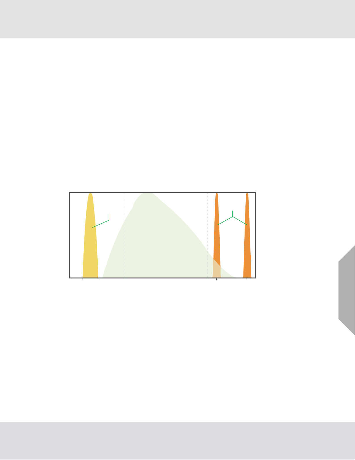
Ultraviolet Region Infrared Region
UV Detector’s
Spectral
Sensitivity
Visible Region
Sun’s Radiation
Reaching Earth
IR Detector’s
Spectral
Sensitivity
Relative Energy
185 nm 260 nm
Fig. 1 Spectral Response of UV and IR Radiation Detectors
Wavelength
2.95 μm
(Hydrogen Detector)
If the device senses only UV radiation (such as arc welding) or only IR radiation (such as a large
modulating hot object), an alarm does not occur. If the device senses both UV and IR radiation in the
correct combination and intensity, as set by an algorithm in the microcomputer, the device identifies a
fire and sends the following output:
• 4 - 20 mA signal
• Immediate Alarm Low output
• Time-delayed Alarm High output
• RS-485 Modbus RTU output
• HART communication
4.35 μm
US
FL500 UV/IR, FL500-H2 Flame Detector
7
Page 8

The FL500 has the following features:
• Compact unitized design
• Wide field of view
• Continuous optical path monitoring (COPM)
• 4 - 20 mA source or sink, alarm relays, and Modbus RTU RS-485 standard
• HART 7 communication
• False alarm prevention
Description
Fig. 2 FL500 UV/IR, FL500-H2 Flame Detector
The FL500 is compatible with the General Monitors TA402A trip amplifier, FL802 controller, and other
equipment that accepts 4 - 20 mA output. The device can be connected directly with alarm and
suppression devices or switched input modules through integral relays. If the HART protocol is used
with the FL802 controller, it is necessary to use the special HART signal (1.25 - 20 mA).
Because the FL802 controller is not CE marked, it cannot be supplied to the European
Union (EU).
2.2 Continuous Optical Path Monitoring (COPM)
COPM does a check of the device's optical path (from the internal UV and IR detectors through an air
gap then the optical window) and related electronic circuitry every 2 minutes. If the optical window is
blocked by unwanted objects such as ice, dirt, or debris for two consecutive checks, the device activates the following Fault output:
• 2.0 mA signal
• Fault relay de-energizes
• Modbus signal
After a COPM Fault occurs, COPM occurs every 30 seconds until the Fault condition is removed.
When the Fault condition is removed, COPM continues every 2 minutes.
Because COPM does a check of the optical path every 2 minutes and two consecutive
checks must fail before a Fault occurs, it can be up to 3 minutes before the device identifies a blockage.
US
Refer to Section 5.2 "Cleaning the Optical Window and Reflectors" for maintenance instructions.
FL500 UV/IR, FL500-H2 Flame Detector
8
Page 9

2.3 LED Operation Mode Definitions
The LEDs show the following modes of operation for the device.
Device Status Alternate Mode Standard Mode
No Power All LEDs OFF
Initial Power On All LEDs blink alternately for 10 s
Green LED = ON
Ready/Normal
Fault - COPM
Fault - Other
Alarm Low
Alarm High
Yellow LED = OFF
Red LED = OFF
Green LED = ON Green LED = OFF
Yellow LED = Blinking slowly (1 Hz)
Red LED = OFF
Green LED = ON Green LED = OFF
Yellow LED = ON
Red LED = OFF
Green LED = ON Green LED = OFF
Yellow LED = OFF
Red LED = Blinking slowly (1 Hz)
Green LED = ON Green LED = OFF
Yellow LED = OFF
Red LED = ON
Description
Green LED = ON with heartbeat
(5 s ON, 0.5 s OFF)
FL500 UV/IR, FL500-H2 Flame Detector
US
9
Page 10

3 Installation
WARNING!
Do not install or operate a device that is damaged.
Install the device in a location away from conditions (such as high-pressure steam) where electro-
static charge can collect on nonconducting surfaces. This equipment uses an external nonmetallic
coating. If extreme levels of electrostatic charge collect, ignition can occur.
Make sure that there is no physical blockage from permanent objects such as structures and
equipment or temporary objects such as personnel and vehicles in the sensor's field of view.
If there is physical blockage in the sensor's field of view, the device cannot accurately monitor the
area for flame.
Keep the device safe from vibration and mechanical shock, which can cause damage.
Failure to obey these warnings can result in serious injury or death.
3.1 Required Tools
• 5 mm Allen wrench (included with the device)
• Flat-blade screwdriver, maximum 1/8 in. width
• No. 2 Philips screwdriver
• 10 mm Allen wrench
• Adjustable wrench
Installation
3.2 Locations
Use the information in Section 3.2.1 "Field of View" and Section 3.2.2 "Environmental Factors" to
select the best location to install the device.
US
FL500 UV/IR, FL500-H2 Flame Detector
10
Page 11
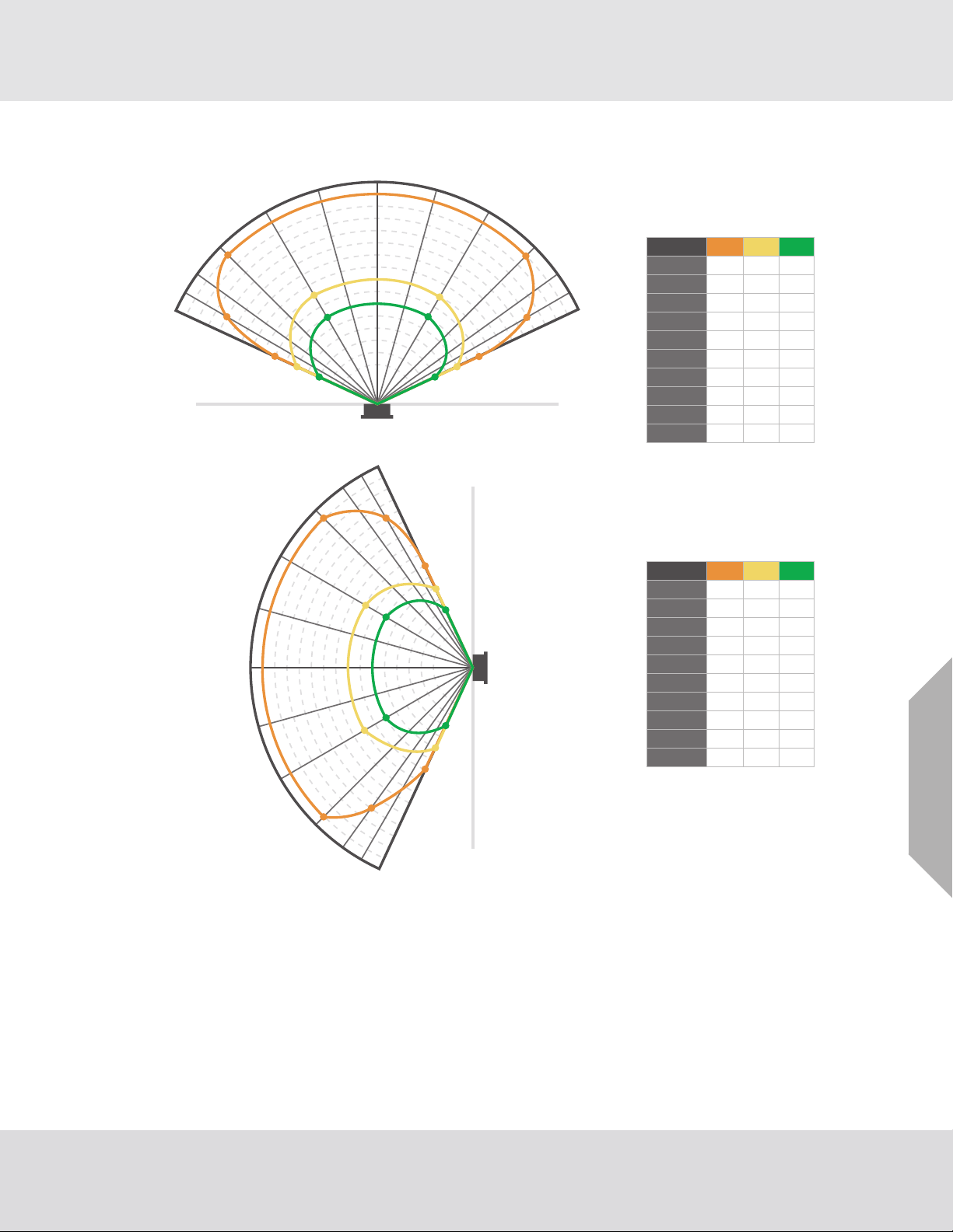
3.2.1 Field of View
Gas Performance:
HEPTANE
65°
60°
55°
45°
30°
15°
0°
20’
25’
30’
35’
40’
45’
50’
55’
60’
65’
70’
75’
80’
85’
90’
15°
30°
45°
55°
60°
65°
65°
60°
55°
45°
30°
15°
0°
20’25’30’35’
40’
45’50’
55’60’
65’70’
75’80’
85’90’
15°
30°
45°
55°
60°
65°
Horizontal High Med Low
Vertical High Med Low
Gas Performance:
HEPTANE
90’ 55’ 45’
55’ 45’
55’ 45’
90’
90’
75’
0°
± 15°
30°
- 30°
45°
75’- 60°
50’ 40’ 30’65°
50’ 40’ 30’- 65°
- 45°
60°
90’ 55’ 45’
55’ 45’
55’ 45’
90’
90’
75’
0°
± 15°
30°
- 30°
45°
60’- 60°
50’ 40’ 30’65°
50’ 40’ 30’- 65°
- 45°
60°
Installation
Fig. 3 Heptane Field of View
US
FL500 UV/IR, FL500-H2 Flame Detector
11
Page 12
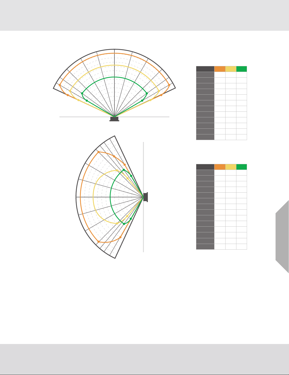
Installation
Gas Performance:
METHANE
65°
60°
55°
45°
30°
15°
0°
20’
25’
30’
35’
40’
45’
50’
55’
60’
65’
70’
75’
80’
15°
30°
45°
55°
60°
65°
65°
60°
55°
50°
45°
30°
15°
0°
20’
25’
30’
35’
40’45’
50’
55’60’
65’
70’75’
80’
15°
30°
45°
55°
50°
60°
65°
HorizontalHigh MedLow
Gas Performance:
METHANE
VerticalHigh MedLow
80’ 60’ 45’
80’
0°
± 15°
30°
- 30°
40°
80’- 45°
65’ 50’ 45’ 55°
65’ 50’ 45’- 55°
40’ 35’60°
35’ 35’- 60°
- 40°
45°
80’ 60’ 45’
80’ 50’
80’ 50’
35’
35’
65’ 45’
65’ 45’
0°
± 15°
30°
− 30°
40°
− 40°
45°
− 45°
50°
− 50°
55°
− 55°
50’ 35’
60°
60’ 35’
− 60°
Fig. 4 Methane Field of View
FL500 UV/IR, FL500-H2 Flame Detector
US
12
Page 13

Installation
15°
30°
55°
50°
45°
40°
30°
15°
25’
0°
30’35’40’
15°
30°
40°
45°
50°
55°
Fig. 5 Methanol Field of View
0°
60°
60°
40’
35’
30’
25’
20’
15’
10’
15°
30°
Gas Performance:
40°40°
45°45°
50°50°
55°55°
60°60°
METHANOL
Horizontal High Med Low
40’ 30’ 25’0°
± 15°
30°
− 30°
± 40°
45°
− 45°
40’ 30’ 25’50°
40’ 30’ 25’− 50°
20’55°
20’− 55°
25’ 20’60°
25’ 20’− 60°
Gas Performance:
METHANOL
Vertical High Med Low
40’ 30’ 25’0°
± 15°
10’
15’20’
30°
− 30°
40°
− 40°
50° 40’ 30’ 25’
− 50° 40’ 30’ 25’
55° 20’
− 55° 20’
60°
30’ 20’
30’ 20’
− 60°
US
FL500 UV/IR, FL500-H2 Flame Detector
13
Page 14

Installation
15°
30°
55°
50°
45°
40°
30°
15°
0°
50’55’60’
15°
30°
40°
45°
50°
55°
Fig. 6 Propane Field of View
0°
60°
30’35’40’45’
60°
60’
55’
50’
45’
40’
35’
30’
25’
20’
15’
10’
15°
30°
Gas Performance:
40°40°
45°45°
50°50°
55°55°
60°60°
PROPANE
Horizontal High Med Low
60’ 45’ 25’0°
± 15°
30°
− 30°
40°
− 40°
− 45°
60’ 45’ 20’
55°
60’ 45’ 20’− 55°
45’ 25’60°
45’ 30’− 60°
25’45°
25’
Gas Performance:
PROPANE
Vertical High Med Low
60’ 45’ 25’0°
25’
10’
15’20’
± 15°
30°
− 30°
40°
− 40°
− 45°
55°
25’
35’
25’
35’
20’45°
25’
20’
25’
60’
60’− 55°
50’60°
50’− 60°
US
FL500 UV/IR, FL500-H2 Flame Detector
14
Page 15

Installation
15°
30°
50°
45°
40°
30°
15°
0°
15°
30°
40°
45°
50°
Fig. 7 Ethane Field of View
55°
55°
0°
60°
60°
60’
55’
50’
45’
40’
35’
30’
25’
20’
15’
10’
15°
30°
Gas Performance:
40°40°
45°45°
50°50°
55°55°
60°60°
ETHANE
Horizontal High Med Low
60’ 40’ 30’0°
± 15°
30°
− 30°
40°
− 40°
45°
− 45°
50°
− 50°
60°
− 60°
40’ 30’
40’ 30’
30’ 25’
30’ 25’
60’
60’
55’
55’
Gas Performance:
ETHANE
Vertical High Med Low
60’ 40’ 30’0°
± 15°
10’15’20’25’30’35’40’45’50’55’60’
30°
− 30°
40°
− 40°
45°
− 45°
50°
− 50°
60°
− 60°
40’ 30’
40’ 30’
30’ 25’
30’ 25’
60’
60’
55’
55’
US
FL500 UV/IR, FL500-H2 Flame Detector
15
Page 16

Installation
15°
30°
50°
45°
40°
30°
15°
0°
15°
30°
40°
45°
50°
Fig. 8 Butane Field of View
55°
55°
0°
60°
60°
55’
50’
45’
40’
35’
30’
25’
20’
15’
10’
15°
30°
Gas Performance:
40°40°
45°45°
50°50°
55°55°
60°60°
BUTANE
Horizontal High Med Low
55’ 35’ 25’0°
± 15°
30°
− 30°
40°
− 40°
45°
− 45°
50°
− 50°
55°
− 55°
60°
− 60°
25’ 20’
25’ 20’
20’
20’
55’
55’
45’
45’
25’
25’
Gas Performance:
BUTANE
Vertical High Med Low
55’ 35’ 25’0°
± 15°
10’15’20’25’30’35’40’45’50’55’
30°
− 30°
40°
− 40°
45°
− 45°
55°
− 55°
60°
− 60°
25’
25’
25’ 20’
25’ 20’
55’
55’
45’
45’
US
FL500 UV/IR, FL500-H2 Flame Detector
16
Page 17

Installation
Gas Performance:
HYDROGEN
Horizontal High Med Low
Gas Performance:
HYDROGEN
Vertical High Med Low
60’ 40’ 30’
40’ 30’
0°
± 15°
± 30°
40°
45°
60’
± 55° 40’
50’
35’
50’ 35’
60°
- 65°
- 45°
± 50°
60’ 25’ 20’
60’ 25’ 20’
60’ 25’ 20’
25’
60’ 20’ 20’
60’ 25’ 20’
20’ 20’
60’
50’
50’ 15’
15’
0°
± 15°
± 30°
40°
45°
- 45°
- 50°
± 55°
60°
- 60°
65°
60’
40’ 30’60’
30’
40’
60’
40’60’ 30’
20’
-65°
-60°
-55°
-50° 50°
-45°
-30°
-15°
0°
5’
10’
15’
20’
25’
30’
35’
40’
45’
50’
55’
60’
15°
30°
45°
40°
55°
60°
65°
-60°
-55°
-50° 50°
-45°
-30°
-15°
0°
5’
10’
15’
20’
25’
30’
35’
40’
45’
50’
55’
60’
15°
30°
45°
40°
55°
60°
65°
Response Times and Field of View data were derived by testing the FL500-H2 flame
detector with a hydrogen flame from a 6 inches square custom burner with
1600 orifices. The flame height was approximately 32 inches. The FL500-H
does not
2
have FM approval.
Fig. 9 Hydrogen Field of View FL500-H2 horizontal
US
FL500 UV/IR, FL500-H2 Flame Detector
17
Page 18

3.2.2 Environmental Factors
WARNING!
Do NOT install the device in an area where temperatures will be more than 185°F (85°C).
Failure to obey this warning can result in serious injury or death.
Make sure that the device is in an area where ice, dirt, or debris cannot collect on the optical window.
If ice, dirt, or debris collects on the optical window, a COPM Fault occurs.
To maintain the device enclosure's IP66/IP67 and Type 6P ingress ratings, use a nonhardening
sealant to install stopping plugs on conduit/cable entries that are not used.
3.3 Mounting
Use the mounting bracket (PN 71370-1) and hardware to install the device on a wall, pole, or other
surface. The design of the mounting bracket lets you adjust optical alignment while keeping the device
in a fixed position.
To attach the mounting bracket to drywall, install at least two fasteners to the stud behind the drywall
to give support for the weight of the device. The recommended fastener is a 3-in. #12 screw.
Use the dimensions shown in Figures 10 through 14 to install the device correctly. Make sure that the
device:
• Is in a location where personnel and objects cannot cause a blockage of the field of view
• Is in a location that is convenient for visual inspection and cleaning
• Is in a location where ice, dirt, or debris cannot collect on the optical window
• Points downward to prevent dust and moisture from collecting on the optical window
Installation
General Monitors does not recommend the use of cable shoes or crimps on any junction
box or housing wiring terminals. Poor crimping can cause a bad connection when
temperature variations occur.
Fig. 10 FL500 Outline Drawing, Front View
US
FL500 UV/IR, FL500-H2 Flame Detector
18
Page 19

Fig. 11 FL500 Outline Drawing, Side View
Installation
Fig. 12 FL500 and Mounting Bracket, Side View
FL500 UV/IR, FL500-H2 Flame Detector
US
19
Page 20

Fig. 13 FL500 and Mounting Bracket, Top View
Installation
Fig. 14 FL500 and Mounting Bracket, Rear View
FL500 UV/IR, FL500-H2 Flame Detector
US
20
Page 21

3.4 Wiring
WARNING!
An approved electrician must do electrical wiring.
All wiring must satisfy the requirements of the applicable NEC, CEC, and local electrical
safety codes.
Install a conduit seal within 18 in. (46 cm) of the device enclosure.
Make sure that all wiring is applicable for use at an ambient temperature of 199.6ºF (93.1°C).
Before installing the wiring for the device, disconnect the power source.
Read all electrical warnings and wiring requirements before connecting power to the device.
In order to maintain the environmental and hazardous area ratings of the detector, install conduit
adapters or plugs in the enclosure per applicable agency requirements.
The device wiring can be damaged by electrostatic discharge (ESD). When you do work with the
device wiring, be careful to touch only the connection points. The warranty does not supply
coverage for components that are damaged by ESD.
Do NOT install wiring in a hazardous atmosphere. Otherwise, electrical shock or ignition can occur.
Failure to obey these warnings can result in serious injury or death.
Installation
Install all wiring connections through the base entries to the terminal block (TB). The terminal block
accepts 14 - 22 AWG (2.1 - 0.3 mm
2
) stranded or solid-core wire.
If conduit is used, to prevent corrosion in the housing due to moisture or condensation, a drain loop
in the conduit is recommended.
For enclosure entry points, a non-hardening sealant should be used on threads.
Fig. 15 FL500 Housing and Base
Remove the insulation from each wire to 0.25 in. (0.64 cm).
Use the correct cables for the ambient temperature where the device is installed.
US
FL500 UV/IR, FL500-H2 Flame Detector
21
Page 22

Installation
Fault 2 Alarm Reset
Fault C
Fault 1
Data −
RS485
Control Device
PLC, DCS, ETC
COM (24 V-return)
+−
Power Supply
Fig. 16 Wiring Diagram
Data +
No Connection
0-20 mA
+ 24 VDC
Chassis Ground
Protection Circuits for Relay Contacts
WARNING!
1234567 8910
11 12 13 14 15 16 17 18 19 20
TB2TB1
No Connection
No Connection
Alarm Test
Alarm High 2
Alarm High 1 Alarm High Relay
Alarm High C
Alarm Low C
Alarm Low 1
Alarm Low 2
Normally
Open Switch
Normally
Open Switch
Alarm Low Relay
Protect relay contacts from transient and over-voltage conditions. Attach a clamp to all inductive loads
(bells, buzzers, relays) on dry relay contacts as shown. Inductive loads that do not have a clamp
attached can cause voltage spikes of more than 1000 Volts. Voltage spikes of this magnitude can
cause false alarms and damage to the contacts.
Failure to obey this warning can result in serious injury or death.
(1) To connect the wire to the terminal block, install the conductor in the connection space as shown.
(2) Use a flat-blade screwdriver to tighten the related screw terminal.
US
FL500 UV/IR, FL500-H2 Flame Detector
22
Page 23

3.5 Terminal Connections
TERM#TERM#
TB2TB1
11 12 13 14 15 16 17 18 19 20
1234567 8910
Chassis
COM (24 V - Return)
+ 24 VDC
0-20 mA
No Connection
Data +
Data −
Fault 1
Fault C
Fault 2
Alarm Low 2
Alarm Low 1
Alarm Low C
Alarm High C
Alarm High 1
Alarm High 2
Alarm Test
No Connection
No Connection
Alarm Reset
There are 20 terminal connections. The following sections give descriptions and specifications for
each connection.
Installation
3.5.1 TB2, Alarm High Relay Connection
Fig. 17 Field Terminations
The output for the SPDT Alarm High relay has a time delay that can be set for 2, 4, 8, or 10 seconds.
Alarm High output can be normally energized or normally de-energized, latching or non-latching.
All options can be set through Modbus, HART, or the DIP switch. Refer to Section 4.2 "Changing
Device Settings" for instructions.
TB2
Position
17 C Common Common
16 1 Normally Closed Normally Open
15 2 Normally Open Normally Closed
Alarm High
Relay
Relay Contact
(De-Energized)
Relay Contact
(Energized)
US
FL500 UV/IR, FL500-H2 Flame Detector
23
Page 24

3.5.2 TB2, Alarm Low Relay Connection
The output for the SPDT Alarm Low relay is immediate. Alarm Low output can be normally energized
or normally de-energized, latching or non-latching.
All options can be set through Modbus, HART, or the DIP switch. Refer to Section 4.2 "Changing
Device Settings" for instructions.
Installation
TB2
Position
18 C Common Common
19 1 Normally Closed Normally Open
20 2 Normally Open Normally Closed
3.5.3 TB1, Fault Relay Connection
The standard configuration for the SPDT Fault relay is normally energized and non-latching. This
configuration cannot be changed.
The Fault relay is activated during the time-out function, a low-power or loss-of-power condition, and
a COPM Fault. For the duration of these conditions, the Fault relay de-energizes and the signal for
analog output decreases to 0 mA (2 mA for a COPM Fault).
TB1
Position
9C C C
8 1 Normally Closed Normally Open
10 2 Normally Open Normally Closed
3.5.4 Alarm Reset Switch
Use the Alarm Reset switch to set latched Alarm High or Alarm Low output that is no longer applicable
back to its initial condition.
Do the following:
Alarm Low
Relay
Fault Relay
Relay Contact
(De-Energized)
Relay Contact
(De-Energized)
Relay Contact
(Energized)
Relay Contact
(Energized)
(1) Connect one contact of a normally open momentary switch to TB2 Terminal 11.
(2) Connect the other contact to COM (device Common).
(3) Push and release the Alarm Reset switch.
Position Function
TB2 POS 11 RESET
TB2 POS 14 TEST
Multiple devices cannot be put in a daisy-chain configuration to use the Alarm Reset
switch. Each latching Alarm Low and Alarm High output must be reset manually.
FL500 UV/IR, FL500-H2 Flame Detector
US
24
Page 25

3.5.5 Analog Output, Modbus and HART
The 0 - 20 mA output is equivalent to the following analog output:
Condition Modbus HART (Normal) HART (Special)
Startup 0 - 0.2 mA 3.5 ±0.2 mA 1.25 ±0.2 mA
Fault 0 - 0.2 mA 3.5 ±0.2 mA 1.25 ±0.2 mA
COPM Fault 2.0 ±0.2 mA 3.5 ±0.2 mA 2.0 ±0.2 mA
Ready 4.05 ±0.2 mA 4.05 ±0.2 mA 4.05 ±0.2 mA
IR 8.0 ±0.2 mA 8.0 ±0.2 mA 8.0 ±0.2 mA
UV 12.0 ±0.2 mA 12.0 ±0.2 mA 12.0 ±0.2 mA
Alarm Low 16.0 ±0.2 mA 16.0 ±0.2 mA 16.0 ±0.2 mA
Alarm High 20.0 ±0.2 mA 20.0 ±0.2 mA 20.0 ±0.2 mA
The maximum analog output load, including wiring, is 600 ohms.
In normal HART mode, the current output does not go below 3.5 mA. Modbus sends 2.0 mA output
for COPM (as if HART was not there) to make a constant Modbus program available. The digital HART
protocol sends the actual current output. When the Alarm High or Alarm Low relays are latched, the
highest output current is also latched. The output current goes back to 4.0 mA when the Alarm Reset
switch relay is activated.
The special HART mode lets the current decrease to 1.25 mA. The HART protocol continues to
operate. Use the special HART mode with products that require 2 mA output for COPM, 1.5 mA output
when the device is offline, and 0 mA output for a Fault condition.
The Modbus protocol is used to configure the device or to find the status of the device.
For information about Modbus, refer to the FL500 Modbus Communication Operating Manual
(PN 10193214).
For information about HART, refer to the FL500 HART Communication Operating Manual
(PN 10193215).
TB1 Position Connection
6DATA +
7DATA -
Installation
US
FL500 UV/IR, FL500-H2 Flame Detector
25
Page 26

3.6 Cable Lengths
Use the following cable lengths (maximum 50-ohm loop) for interfaces with impedance devices that
have 250-ohm input.
Installation
Cable AWG Run (ft) Cable (mm
2
) Run (m)
14 9000 2.50 2750
16 5800 1.50 1770
18 3800 1.00 1160
20 2400 0.75 730
22 1700 0.50 520
Use the following cable lengths (maximum 20-ohm loop) for a 24 Vdc power supply.
Cable AWG Run (ft) Cable (mm
2
) Run (m)
14 6588 2.08 2013
16 4146 1.31 1266
18 2608 0.823 796
20 1642 0.519 501
22 1055 0.33 321
3.7 Power Supply
The voltage range for the power supply is 20 - 36 Vdc at the device. Low voltage occurs at approximately 18.5 Vdc.
TB1 Position Connection
324 Vdc
2COM
3.8 Chassis Ground
Use this connection to ground the device when you do any work with the wiring. General Monitors
recommends that the chassis be grounded at all times.
TB1 Position Connection
1 CHAS GND
3.9 Fire Cards or Panels
General Monitors factory-fits end-of-life (EOL) and Alarm High resistors for devices that are wired
together to do monitoring through standard fire cards.
When the FL500 is used with a General Monitors IN042 card, the Alarm High resistor is set to 470 ohm
and the EOL resistor is set to 5.6K. The EOL resistor is onboard the IN042 card and can be selected
through the DIP switch.
European Union (EU) approved applications: Make sure that interconnecting cables
have an overall screen, or screen and armor. Cables BS5308 Part 2, Type 2, or equivalent are approved for use. To make a positive electrical connection, make sure that the
cable armor connects to an applicable cable gland at the device.
US
FL500 UV/IR, FL500-H2 Flame Detector
26
Page 27

3.10 Cable Termination in a Nonhazardous Area
WARNING!
Do NOT connect or disconnect equipment when power is supplied to the device. Doing so can result
in serious damage to the equipment. The warranty does not supply coverage for equipment that is
damaged in this way.
Failure to obey this warning can result in serious injury or death.
Connect the cable armor to safety earth in a nonhazardous area.
Connect the cable screen (drain wire) to instrument earth in a nonhazardous area.
Connect the power supply OV return to instrument earth in a nonhazardous area.
Keep interconnecting cables isolated from the power cable and other noisy cables, such as cables for
radio transmitters, welders, switch mode power supplies, inverters, battery chargers, ignition systems,
generators, switch gear, arc lights, and other high-frequency or high-power switching process equipment. Keep a separation of at least 3 ft (1 m) between instrument and other cables. An increased
separation is necessary for long, parallel cable runs. Do not put instrument cable trenches close to
lightning conductor earthing pits.
Installation
FL500 UV/IR, FL500-H2 Flame Detector
US
27
Page 28

4 Operation
WARNING!
Make sure that there is no physical blockage from permanent objects such as structures and
equipment or temporary objects such as personnel and vehicles in the sensor's field of view. If
there is physical blockage in the sensor's field of view, the device cannot accurately monitor the
area for flame.
Make sure that there is no ice, dirt, or debris on the optical window. Blockage of the optical window
can result in a Fault condition.
During a Fault condition, the device does not monitor the area for flame.
Failure to obey these warnings can result in serious injury or death.
4.1 Start-Up
Before you supply power to the device, do the following:
• Replace the red dust cap with an approved cable gland.
• Disconnect external devices such as automatic extinguishing fire suppression systems to prevent
activation.
• Make sure that the settings for the DIP switch are in the correct configuration.
Refer to Section 4.2.1 "Using the DIP Switch" for instructions.
• Make sure that the device is mounted and wired correctly.
• Make sure that there is no blockage of the field of view for each device.
• Make sure that the optical window and reflectors are clean.
Refer to Section 5.2 "Cleaning the Optical Window and Reflectors" for cleaning instructions.
• Make sure that the power supply is connected correctly.
Apply power to the device. Each device starts a self-test start-up sequence. For the first 10 seconds,
the device sends 0 mA output, the Fault relay stays de-energized, and the green, yellow, and red
LEDs flash. After this 10-second period, the device sends 4 mA output, the Fault relay is energized,
the red LED goes off, and the green LED comes on and flashes every 5 seconds.
After the start-up sequence is complete, do a sensitivity check.
Refer to Section 4.3 "Sensitivity Check" for instructions.
Operation
US
4.2 Changing Device Settings
All device settings can be changed through Modbus, HART, or the DIP switch. Settings made through
Modbus and HART override settings made through the DIP switch.
4.2.1 Using the DIP Switch
To change device settings through the DIP switch, do the following:
(1) Use a flat-blade screwdriver to remove the screws that attach the detector head to the base
assembly.
(2) Find the DIP switch.
(3) Make the applicable switch assignments.
(4) Cycle power to the device.
FL500 UV/IR, FL500-H2 Flame Detector
28
Page 29

Operation
Fig. 18 DIP Switch Location
On the DIP switch, the nomenclature "ON/CLOSED" is used when the switch is pushed in on the side
labeled "ON" or "CLOSED" (opposite the side labeled "OPEN"). The nomenclature "OFF/OPEN" is
used when the switch is pushed in on the side with the number related to the switch position or the
side labeled "OPEN".
The time delay is the amount of time an Alarm Low condition continues before an Alarm High condition
occurs.
Option
Position 12345678910
High Sensitivity OFFOFF--------
Medium Sensitivity ONOFF--------
Low Sensitivity OFFON--------
2-second Alarm High Time Delay --OFFON------
4-second Alarm High Time Delay --OFFOFF------
8-second Alarm High Time Delay --ONOFF------
10-second Alarm High Time Delay --ONON------
Alarm High Non-Latching ----OFF-----
Alarm High Latching ----ON-----
Alarm Low Non-Latching -----OFF----
Alarm Low Latching -----ON----
Alarm High Normal Energized ------ON---
Alarm High Normal
De-Energized
Alarm Low Normal Energized -------ON--
Alarm Low Normal
De-Energized
Alternate LED ---------ON
HART Enabled --------ON-
------OFF---
-------OFF--
US
FL500 UV/IR, FL500-H2 Flame Detector
29
Page 30

4.2.2 Using Modbus or HART
To use the HART protocol, it is necessary to select the applicable current (1.25 mA or 3.5 mA).
The factory default setting is 3.5 - 20 mA. This setting can only be changed through HART or Modbus.
Settings for Modbus and HART can be changed through the DIP switch.
For information about changing device settings through Modbus, refer to the FL500 Modbus Communication Operating Manual (PN 10193214).
For information about changing device settings through HART, refer to the FL500 HART Communication Operating Manual (PN 10193215).
4.3 Sensitivity Check
Use the TL105 Test Lamp or the Alarm Test feature to make sure that each device operates correctly.
If the device does not operate correctly, refer to Section 7 "Troubleshooting" for instructions.
4.3.1 TL105 Test Lamp
The TL105 test lamp is a battery operated, rechargeable test source used to make sure that operation
of the device is correct. The test lamp has a high-energy broadband radiation source that emits sufficient energy in both the UV and IR spectra to activate the UV and IR detectors. To simulate a fire, the
TL105 test lamp automatically flashes at the correct rate for different models. When fully charged, the
internal batteries operate continuously for 30 minutes. When the battery charge goes below the level
necessary to supply the correct intensity, an internal low-voltage circuit stops operation of the test
lamp until the batteries are recharged. For recharging instructions, refer to the TL105 Instruction
Manual (PN MANTL105).
Operation
Fig. 19 TL105 Test Lamp
(1) Make sure that the batteries are fully charged and the rotary switch is set at position 4
(FL4000 position).
(2) Stand 15 - 20 ft (5 - 6 m) away from the FL500 UV/IR.
Stand up to 30 ft (9 m) away from the FL500 H
.
2
(3) Point the TL105 test lamp directly at the front of the device.
(4) Shake the test lamp from side to side or up and down. Motion increases the simulation of flames
flickering and increases the response of the device to the test lamp.
If device operation is correct, after a few flashes of the test lamp, an Alarm Low condition occurs.
If the test lamp stays pointed at the device for the period of the time-delay setting, an Alarm High
condition occurs.
To conserve the battery charge, operate the test lamp only as long as necessary to do
a test of each device.
FL500 UV/IR, FL500-H2 Flame Detector
US
30
Page 31

4.3.2 Alarm Test Feature
To use the Alarm Test feature, do the following:
(1) Connect one contact of a normally open, momentary switch to TB2 Terminal 14.
(2) Connect the other contact to TB1 Terminal 2 (COM).
(3) Activate the switch for the period set for the time delay (2 - 10 seconds).
• If the device senses the source, it immediately sends Alarm Low output, then the time-delayed
Alarm High ouput.
• If the device does not sense the source, it sends Fault output and does the test again every
10 seconds.
The Alarm Test feature can be used through Modbus and HART.
Multiple devices cannot be put in a daisy-chain configuration to do testing for Alarm High
output.
Operation
FL500 UV/IR, FL500-H2 Flame Detector
US
31
Page 32

5 Maintenance
WARNING!
Repair or alteration of the device beyond the scope of the maintenance instructions in this manual
or by anyone other than General Monitors or General Monitors-approved service personnel can
cause incorrect operation of the device and put persons who use this device for their safety at risk
of serious injury or death.
The device has components that can be damaged by electrostatic discharge (ESD). When you do
work with the device wiring, be careful to touch only the connection points. The warranty does not
supply coverage for components that are damaged by ESD.
Failure to obey these warnings can result in serious injury or death.
General Monitors recommends that maintenance intervals be set through a documented procedure
that includes a maintenance log kept by plant personnel or third-party testing services.
5.1 Regular Maintenance
WARNING!
Maintenance
Use ONLY a damp cloth to clean the device. Otherwise, electrical shock or ignition from ESD can
occur.
Failure to obey this warning can result in serious injury or death.
Clean the optical window every 30 days at a minimum. Refer to Section 5.2 "Cleaning the Optical
Window and Reflectors" for instructions. Do sensitivity checks regularly. Refer to Section 4.3 "Sensitivity Check" for instructions.
Examine, clean the optical window, and do sensitivity checks more frequently for
devices that are installed in dirty areas.
5.2 Cleaning the Optical Window and Reflectors
WARNING!
Use ONLY Industrial Strength Windex® with Ammonia D (General Monitors PN 10272-1) to clean the
optical window. The optical window material is sapphire, not glass. Using any other commercial glass
cleaner will cause damage to the optical window. The warranty does not supply coverage for optical
windows that are damaged in this way.
Failure to obey this warning can result in serious injury or death.
Remove debris and film buildup on the optical window and reflectors regularly to make sure that the
device has the correct sensitivity and to prevent COPM Faults. General Monitors recommends that
you clean the optical window and reflectors every 30 days at a minimum. Clean the optical window
and reflectors more frequently for devices that are installed in dirty areas.
US
(1) Use a clean, soft, lint-free cloth, tissue, or cotton swab soaked with Industrial Strength Windex
with Ammonia D to clean the optical window and UV/IR reflectors.
(2) Use a clean, dry, cloth to rub the optical window until it is clean. Do NOT touch the lens with your
fingers.
(3) Let the optical window and UV/IR reflectors air-dry fully.
FL500 UV/IR, FL500-H2 Flame Detector
32
Page 33

5.3 Annual Maintenance
Make sure that all wiring and terminal connections are connected correctly.
Make sure that the mounting for all integral safety equipment, including but not limited to following
components, is stable:
• Power supplies
• Control modules
• Field detection devices
• Signaling devices
• Accessories connected to field and signaling devices
6Storage
WARNING!
Keep the device safe from vibration and mechanical shock, which can cause damage.
Failure to obey this warning can result in serious injury or death.
Keep the device in a clean area with an ambient temperature of -40°F to 185°F (-40°C to 85°C) and
a humidity range of 0% to 95% RH noncondensing.
For extended storage, do the following:
Storage
(1) If possible, keep the device in the mold as shipped by the manufacturer.
(2) Install the red dust caps in the cable entry holes.
(3) Seal the device and a desiccant in a plastic bag.
(4) Seal the plastic bag inside another plastic bag.
US
FL500 UV/IR, FL500-H2 Flame Detector
33
Page 34

Troubleshooting
7 Troubleshooting
WARNING!
Repair or alteration of the device beyond the scope of the maintenance instructions in this manual or
by anyone other than General Monitors or General Monitors-approved service personnel can cause
incorrect operation of the device and put persons who use this device for their safety at risk of serious
injury or death.
During a Fault condition, the device does not monitor the area for flame.
Failure to obey these warnings can result in serious injury or death.
7.1 Troubleshooting Table
The troubleshooting table gives information about common faults that occur during commissioning
and operation. These common faults can be repaired by a competent operator.
Before you do the following corrective actions, inhibit or disconnect the external alarm wiring to
prevent an accidental Alarm High condition.
Problem Possible Cause Corrective Action
No output signal and all LEDs
are off
2 mA signal, green LED is off,
yellow LED is blinking
0 mA, 1.25 mA, or 3.5 mA
signal, and yellow LED is on
Constant 8 mA signal with no
known radiation to device
Constant 12 mA signal with no
known radiation to device
Constant 16 mA or 20 mA
signal (Alarm Low or Alarm
High) with no known radiation
at device
No dc power to the device
Device is in COPM Fault
Low supply voltage or other
fault
Background IR radiation at
device
Background UV radiation at
device
Background UV radiation at
device
Make sure that 24 Vdc is applied with
the correct polarity.
Clean the optical window and reflectors. Refer to Section 5.2 "Cleaning
the Optical Window and Reflectors" for
instructions.
Make sure that the supply voltage is
≥20 Vdc at the device. If it is, cycle the
power to see if the fault is removed.
Put a cover over the optical window for
10 seconds. If the device senses background IR, and the analog output still
shows 8 mA, contact technical support
for more troubleshooting.
Put a cover over the UV part of the
optical window for 10 seconds. If the
device senses background UV, and
the analog output still shows 12 mA,
contact technical support for more
troubleshooting.
Put a cover over the optical window for
10 seconds. If the analog output still
shows 16 mA or 20 mA, contact technical support for more troubleshooting.
US
If the corrective actions recommended in the troubleshooting table do not correct operation of the
device, return the device to General Monitors for repair.
FL500 UV/IR, FL500-H2 Flame Detector
34
Page 35

7.2 Returning the Device for Repairs
Use the following contact information to return a device to General Monitors for repair. Include a
detailed written description of the problem.
Troubleshooting
UNITED STATES
26776 Simpatica Circle
Lake Forest, CA 92630
IRELAND
Ballybrit Business Park
Galway
H91 H6P2
Republic of Ireland
MIDDLE EAST
P.O. Box 54910
Dubai Airport Freezone
United Arab Emirates
SINGAPORE
35 Marsiling Industrial Estate, Road 3
#04-01
Singapore 739257
Additional locations are available at www.MSAsafety.com.
Phone: +1-949-581-4464
Email: info.gm@msasafety.com
Phone: +353-91-751175
Email: info.gmil@msasafety.com
Phone: +971-4-294-3640
Email: gmdubai.main@msasafety.com
Phone: +65-6350-4500
7.3 Removing the Device from Service Permanently
EU member states must discard devices in accordance with the Waste Electrical and Electronic
Equipment (WEEE) Directive. All other countries or states must discard devices in accordance with
existing federal, state, and local environmental control regulations.
7.4 References and Other Sources of Help
Look for documentation, white papers, and product literature for our complete line of safety products
at http://www.MSAsafety.com/detection.
For more information about the use and performance standards for the device, refer to the following
publications:
• EN 54-10:2002, Fire detection and fire alarm systems - Flame detectors - Point detectors.
British Standards Institute, London, United Kingdom, 2002.
• EN 50130-4, Electromagnetic compatibility. Product family standard: Immunity requirements for
components of fire, intruder, hold up, CCTV, access control and social alarm systems.
British Standards Institute, London, United Kingdom, 2011.
• EN 61000-6-4:2007+A1:2011, Electromagnetic compatibility (EMC). Generic standards. Emission
standard for industrial environments. British Standards Institute, London, United Kingdom, 2007.
US
FL500 UV/IR, FL500-H2 Flame Detector
35
Page 36

8 Specifications
8.1 System Specifications
Product Model FL500 UV/IR
Device location
Environmental ratings Type 6P, IP66/IP67
UV Detector pass band 185 - 260 nanometers
IR Detector center wavelength 4.35 μm
Typical alarm activation
response times
Zeta value
Field of view Refer to Section 3.2.1 "Field of View" for information.
* Applicable to FM approvals only.
Specifications
Class I, Division 1, Groups A*, B, C, and D
Class II, Division 1, Groups E, F, and G
Class III
Ex db IIC T5 Gb
Ex tb IIIC T100°C Db
II 2 G D
-50°C to 85°C under FM, -55°C to 85°C under
CSA/ATEX/IECEx
Fuel Distance (ft) Response Time (s)
n-Heptane
Methane 80 <10
Methanol 40 12
Propane 60 <7
Ethane 60 <3
Butane 55 <3
Zeta = -0.001
The margin of error in the range measurement is estimated at ±5 ft (±1.5 m) due to wind conditions and flame
turbulence.
90
60
6
<3
US
Notes:
Response times and field of view data were derived by testing the device with a 1 ft
cup of heptane on top of a 1-in. layer of water was ignited for each test. These are typical values. The
variation of each fire can cause different results.
The field of view as determined per the requirements of EN 54-10 is limited to ±25 degrees due to the
nature of the test requirements for the Directional Dependence test. This result is based on indoor
bench top testing using a Bunsen burner as the fire source as opposed to outdoor flame testing that
was used to determine the field of view plots in Section 3.2.1 "Field of View".
FL500 UV/IR, FL500-H2 Flame Detector
2
heptane fire. One
36
Page 37

Specifications
Product Model FL500-H
Class I, Division 1, Groups B, C, and D
Class II, Division 1, Groups E, F, and G
Class III
Device location
Environmental ratings Type 6P, IP66/IP67
UV Detector pass band 185 - 260 nanometers
IR Detector center wavelength 2.95 μm
Typical alarm activation
response times
Zeta value
Field of view Refer to Section 3.2.1 "Field of View" for information.
Ex db IIC T5 Gb
Ex tb IIIC T100°C Db
II 2 G D
-55°C to 85°C under CSA/ATEX/IECEx
Fuel Distance (ft) Response Time (s)
Hydrogen 60 <3
Zeta = -0.001
The margin of error in the range measurement is estimated at ±5 ft (±1.5 m) due to wind conditions and flame
turbulence.
2
FL500 UV/IR, FL500-H2 Flame Detector
US
37
Page 38

8.2 Mechanical Specifications
Enclosure material 316 Stainless Steel
Color Red
Finish TGIC polyester powder coat
Height 6.4 in. (16.2 cm)
Width 5.0 in. (12.7 cm)
Depth 4.3 in. (11.0 cm)
Weight 9.4 lb (4.3 kg)
Cable Entry 2 x ¾ in. NPT (M25 adapters included for some configurations)
Earth Terminals
8.3 Electrical Specifications
Nominal supply voltage 24 Vdc
Supply voltage range 20 to 36 Vdc (measured at device)
Maximum operating
supply current
Typical operating
supply current
Peak inrush supply current
Maximum output signal load 600 ohms
Output signal range 0 to 20 mA *
Fault signal 0 to 0.2 mA *
COPM fault signal 2.0 ±0.2 mA *
Ready signal 4.0 ±0.2 mA
IR only signal 8.0 ±0.2 mA
UV only signal 12.0 ±0.2 mA
Alarm Low signal 16.0 ±0.2 mA
Alarm High signal 20.0 ±0.2 mA
Relay contact ratings
RS-485 output
HART
HART impedance RX = 50 K CX = 5 nF
RFI/EMI protection Complies with EN 50130-4 and EN 61000-6-4
Status indicator Three LEDs identify status, fault, and alarm conditions
Specifications
8-32 x 3/8 Philips pan-head screw, stainless steel, zinc-plated, green
dye; external stainless steel tooth lock washer included. Applicable
for connection of 4 mm
200 mA during COPM only
80 to 150 mA
860 mA @ 18.5 VDC, 900 mA @ 24.0 VDC, 964 mA @ 36.0 VDC.
Supply voltages are at the detector
North American Approved Applications:
SPDT, 5A @ 250 Vac, or 5A @ 30 Vdc resistive max.
European Union (EU) Approved Applications:
SPDT, 5A 30V RMS/42.4V Peak, or 5A @ 30 Vdc resistive max.
Modbus RTU
128 devices in series max. (247 devices with repeaters)
Baud rate: 2400, 4800, 9600, or 19200 bps
Fully HART 7 FieldComm compliant. Refer to the FL500 HART
Communication Operating Manual (PN 10193215).
2
or smaller.
US
FL500 UV/IR, FL500-H2 Flame Detector
38
Page 39

8.4 Environmental Specifications
Operating temperature range -67°F to 185°F (-55°C to 85°C)
Storage temperature range -40°F to 185°F (-40°C to 85°C)
Humidity range 0% to 95% RH noncondensing
Approvals
False Alarm Immunity for the FL500 UV/IR and FL500-H
False Alarm Source Distance from FL500 (ft) Trouble / False Alarm
Direct sunlight 3N
Reflected sunlight 3N
Arc weld dc 190A, 7014 rod 15 N
Arc weld ac 90A, 7014 rod 15 N
1500W electrical heater 2N
6000W electrical heater 2N
100W incandescent light 1N
300W incandescent light 1N
Two 34W fluorescent light 1N
500W halogen light 2N
100W UV backlight 3N
250W vapor lamp 3N
Two 25W tungsten incandescent
lamps
3N
2
9 Approvals
FL500 UV/IR is approved for CSA (CSA 18.70180732X), FM, ATEX (Sira 18ATEX1073X),
IECEx (SIR 18.0026X), HART Registered, SIL 3 and EN 54-10.
FL500 H
IECEx (SIR 18.0026X) and HART Registered.
is approved for CSA (CSA 18.70180732X), ATEX (Sira 18ATEX1073X),
2
10 Ordering Information
Standard configuration FL500-3-5-1-2-1-1-1-1
Standard H
See website for all available configuration options.
configuration FL500-3-5-1-2-1-2-1-1
2
FL500 UV/IR, FL500-H2 Flame Detector
US
3.5 mA HART, source current, non-latching relays,
single Modbus, 100% sensitivity, 4 sec delay, stainless steel,
3/4" NPT, mounting bracket
3.5 mA HART, source current, non-latching relays,
single Modbus, 100% sensitivity, 4 sec delay, stainless steel,
hydrogen, 3/4" NPT, mounting bracket
39
Page 40

For local contacts, please visit us at MSAsafety.com
 Loading...