

Page 1
Models FL3100H/FL3101H
UV/IR and UV only
Flame Detectors
The information and technical data disclosed in
this document may be used and disseminated
only for the purposes and to the extent
specifically authorized in writing by General
Monitors.
Instruction Manual DATE 01-16
General Monitors reserves the right to change
published specifications and designs without
prior notice.
MANFL3100H/3101H
Part No. MANFL3100/3101H
Revision H/01-16
Page 2
Models FL3100H/3101H
ii
Page 3

Models FL3100H/3101H
Table of Contents
MODELS FL3100H/FL3101H ........................................................................................................ I
UV/IR AND UV ONLY FLAME DETECTORS ............................................................................... I
TABLE OF FIGURES ................................................................................................................. VII
TABLE OF TABLES .................................................................................................................. VIII
QUICK START GUIDE ................................................................................................................. 1
Mount and Wire the Detector .................................................................................................................. 1
Apply Power to the Detector ................................................................................................................... 4
Testing the Detector Using the TL105 .................................................................................................... 4
1.0INTRODUCTION .................................................................................................................... 5
1.1 Protection for Life ....................................................................................................................... 5
1.2 Special Warnings ....................................................................................................................... 5
1.3 System Integrity Verification ...................................................................................................... 5
2.0PRODUCT DESCRIPTION ..................................................................................................... 7
2.1 General Description ................................................................................................................... 7
3.0INSTALLATION ...................................................................................................................... 8
3.1 Tools Required ........................................................................................................................... 8
3.2 Choosing Product Locations ...................................................................................................... 8
3.2.1 Detector Field of View ................................................................................................... 8
3.2.2 Optical Sensitivity Range .............................................................................................. 8
3.2.3 Environmental Factors .................................................................................................. 8
3.3 Mounting and Wiring ................................................................................................................ 12
3.3.1 Terminal Connections ................................................................................................. 18
3.3.2 Terminal Block TB2 – Alarm Relay Connections ........................................................ 18
3.3.3 Terminal Block TB-2 Warning Relay Connections ...................................................... 19
3.3.4 Fault Relay .................................................................................................................. 19
3.3.5 Alarm Reset Terminal ................................................................................................. 20
3.3.6 Analog Output ............................................................................................................. 20
3.3.7 Cable Requirements ................................................................................................... 21
3.3.8 Power .......................................................................................................................... 21
3.3.9 Modbus Interface ........................................................................................................ 22
3.3.10 Chassis Ground .......................................................................................................... 22
3.3.11 Connection to Fire Cards/Panels ................................................................................ 22
3.3.12 Cable Termination in the Non-Hazardous Area .......................................................... 23
4.0OPERATION ......................................................................................................................... 24
4.1 Checklist ................................................................................................................................... 24
4.2 Start Up .................................................................................................................................... 24
4.3 System Test ............................................................................................................................. 24
4.4 User Selectable Options/Factory Defaults ............................................................................... 24
5.0MODBUS INTERFACE ........................................................................................................ 26
iii
Page 4

Models FL3100H/3101H
Baud Rate ................................................................................................................................ 26
5.1
5.2 Data Format ............................................................................................................................. 26
5.3 Modbus Read Status Protocol (Query/Response) ................................................................... 26
5.3.1 Modbus Read Query Message ................................................................................... 26
5.3.2 Modbus Read Response Message ............................................................................. 27
5.4 Modbus Write Command Protocol (Query/Response) ............................................................ 27
5.4.1 Modbus Write Query Message ................................................................................... 27
5.4.2 Modbus Write Response Message ............................................................................. 28
5.4.3 Function Codes Supported ......................................................................................... 28
5.5 Exception Responses and Exception Codes ........................................................................... 28
5.5.1 Exception Responses ................................................................................................. 29
5.6 Command Register Locations .................................................................................................. 30
5.6.1 Operational Mode Commands .................................................................................... 30
5.7 FL3100H / FL3101H Operational Mode Command Register Details ...................................... 34
5.7.1 Analog (00H) ............................................................................................................... 34
5.7.2 Mode (01H) ................................................................................................................. 34
5.7.3 Status/Error (02H) ....................................................................................................... 34
5.7.4 Faults .......................................................................................................................... 35
5.7.5 UV/IR Only (03H) ........................................................................................................ 35
5.7.6 Model Type (04H) ....................................................................................................... 35
5.7.7 Software Revision (05H) ............................................................................................. 36
5.7.8 COPM Fault (06H) ...................................................................................................... 36
5.7.9 EEPROM Override (07H) ............................................................................................ 36
5.7.10 Options (08H) .............................................................................................................. 36
5.7.11 Comm 1 Address (09H) .............................................................................................. 37
5.7.12 Comm 1 Baud Rate (0BH) .......................................................................................... 37
5.7.13 Comm 1 Data Format (0CH) ....................................................................................... 38
5.7.14 UV Signal Count (0DH) ............................................................................................... 38
5.7.15 IR Signal Count (0EH) ................................................................................................ 38
5.7.16 UV Fault Total (0FH) ................................................................................................... 38
5.7.17 IR Fault Total (10H) ..................................................................................................... 38
5.7.18 Remote Reset (11H) ................................................................................................... 38
5.7.19 Remote Alarm Test (12H) ........................................................................................... 39
5.7.20 Clear COPM Faults (13H) ........................................................................................... 39
5.7.21 Serial Number (15/16H) .............................................................................................. 39
5.7.22 HART Enable (1D) ...................................................................................................... 39
5.7.23 HART Test (1E) ........................................................................................................... 39
5.7.24 Not Used (1F) .............................................................................................................. 40
5.7.25 Comm 1 Total Illegal number of registers Errors (20H) .............................................. 40
5.7.26 Comm 1 Bus Activity Rate % (21H) ............................................................................ 40
5.7.27 Comm 1 Function Code Errors (22H) ......................................................................... 40
5.7.28 Comm 1 Starting Address Errors (23H) ...................................................................... 40
5.7.29 Comm 1 Total Receive Errors (24H) ........................................................................... 40
5.7.30 RXD CRC Errors Hi (25h) ........................................................................................... 40
5.7.31 RXD CRC Errors Lo (Same as Hi) (26h) .................................................................... 40
5.7.32 Comm 1 Overrun Errors (27H) .................................................................................... 40
5.7.33 Comm 1 Parity Errors (28H) ....................................................................................... 40
5.7.34 Comm 1 Framing Errors (29H) ................................................................................... 41
5.7.35 Comm 1 Total UART Receive Errors (2AH) ............................................................... 41
5.7.36 Comm 1 Total Receive Errors (2BH) .......................................................................... 41
5.7.37 Clear Comm 1 UART Errors (2CH) ............................................................................. 41
5.7.38 Clear Comm 1 Modbus Errors (2DH) .......................................................................... 41
5.7.39 HART Current (2E) ...................................................................................................... 41
iv
Page 5

Models FL3100H/3101H
Comm 2 Address (2FH) .............................................................................................. 41
5.7.40
5.7.41 Comm 2 Baud Rate (30H) .......................................................................................... 42
5.7.42 Comm 2 Data Format (31H) ....................................................................................... 42
5.7.43 Not Used (32H) ........................................................................................................... 42
5.7.44 Input Voltage (33H) ..................................................................................................... 42
5.7.45 Alarm Test Voltage (34H) ........................................................................................... 43
5.7.46 Reset Relays Voltage (35H) ....................................................................................... 43
5.7.47 Dip Switch Settings (36H) ........................................................................................... 43
5.7.48 Not Used (37 – 3FH) ................................................................................................... 43
5.7.49 See Event Logging - Section 6.0 (40H – 67H) ............................................................ 43
5.7.50 User Information (68h to 77h) ..................................................................................... 43
5.7.51 Comm 2 Total Illegal Number of Registers Errors (78H) ............................................ 43
5.7.52 Comm 2 Bus Activity Rate % (79H) ............................................................................ 43
5.7.53 Comm 2 Function Code Errors (7AH) ......................................................................... 43
5.7.54 Comm 2 Starting Address Errors (7BH)...................................................................... 43
5.7.55 Comm 2 Total Receive Errors (7CH) .......................................................................... 43
5.7.56 RXD CRC Errors Hi (7DH) .......................................................................................... 44
5.7.57 RXD CRC Errors Lo (Same as Hi) (7EH) ................................................................... 44
5.7.58 Comm 2 Overrun Errors (7FH) ................................................................................... 44
5.7.59 Comm 2 Parity Errors (80H) ....................................................................................... 44
5.7.60 Comm 2 Framing Errors (81H) ................................................................................... 44
5.7.61 Comm 2 Total UART Receive Errors (82H) ................................................................ 44
5.7.62 Not Used (83H) .......................................................................................................... 44
5.7.63 Clear Comm 2 UART Errors (84H) ............................................................................. 44
5.7.64 Clear Comm 2 Modbus Errors (85H) .......................................................................... 44
6.0EVENT LOGGING ................................................................................................................ 45
6.1.1 Faults .......................................................................................................................... 45
6.1.2 Warning ....................................................................................................................... 45
6.1.3 Alarm ........................................................................................................................... 45
6.1.4 Maintenance ................................................................................................................ 45
6.1.5 Setting Clock ............................................................................................................... 45
7.0MAINTENANCE ................................................................................................................... 48
7.1 General Maintenance ............................................................................................................... 48
7.2 Cleaning the Lenses/Light Rods .............................................................................................. 48
7.3 Sensitivity Check ...................................................................................................................... 49
7.3.1 Alarm Test ................................................................................................................... 49
7.3.2 TL105 Test Lamp ........................................................................................................ 50
7.3.3 TL105 Operating Instructions ...................................................................................... 50
7.3.4 TL105 Recharging Instructions ................................................................................... 50
7.4 Storage ..................................................................................................................................... 51
8.0TROUBLESHOOTING ......................................................................................................... 52
8.1 Troubleshooting ....................................................................................................................... 52
8.1.1 Introduction ................................................................................................................. 52
9.0CUSTOMER SUPPORT ....................................................................................................... 53
9.1 Other Sources of Help .............................................................................................................. 53
10.0 APPENDIX ................................................................................................................ 54
v
Page 6

Models FL3100H/3101H
Warranty ................................................................................................................................... 54
10.1
10.2 Principle of Operation ............................................................................................................... 54
10.2.1 UV Detector - FL3100H and FL3101H........................................................................ 54
10.2.2 UV/IR Flame Detector - FL3100H ............................................................................... 55
10.2.3 COPM Circuitry ........................................................................................................... 55
10.2.4 Alarm Test ................................................................................................................... 56
10.2.5 Two-color Visual Indicators ......................................................................................... 56
10.2.6 Three-color Visual Indicators ...................................................................................... 56
10.3 Specifications ........................................................................................................................... 57
10.3.1 System Specifications ................................................................................................. 57
10.3.2 Mechanical Specifications ........................................................................................... 58
10.3.3 Electrical Specifications .............................................................................................. 58
10.3.4 Environmental Specifications ...................................................................................... 59
10.4 Approvals ................................................................................................................................. 59
10.5 Accessories .............................................................................................................................. 59
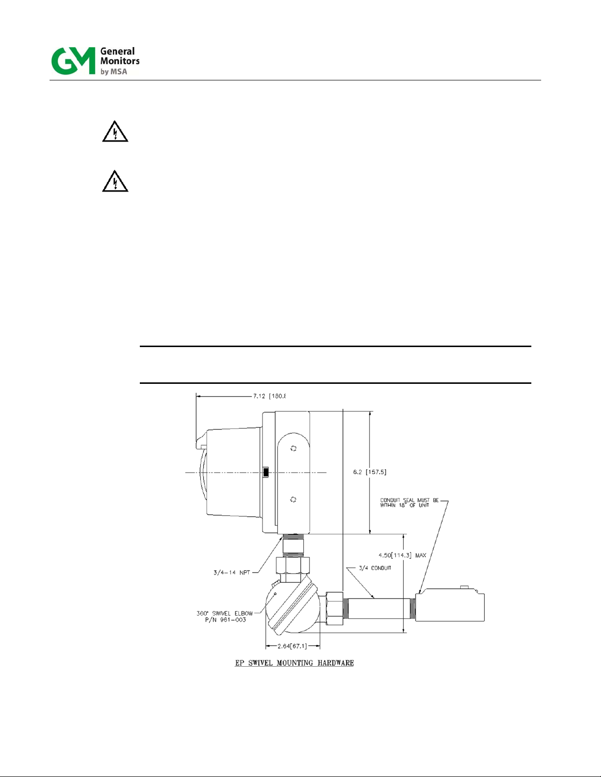
10.5.1 Mounting Swivel/Union ............................................................................................... 59
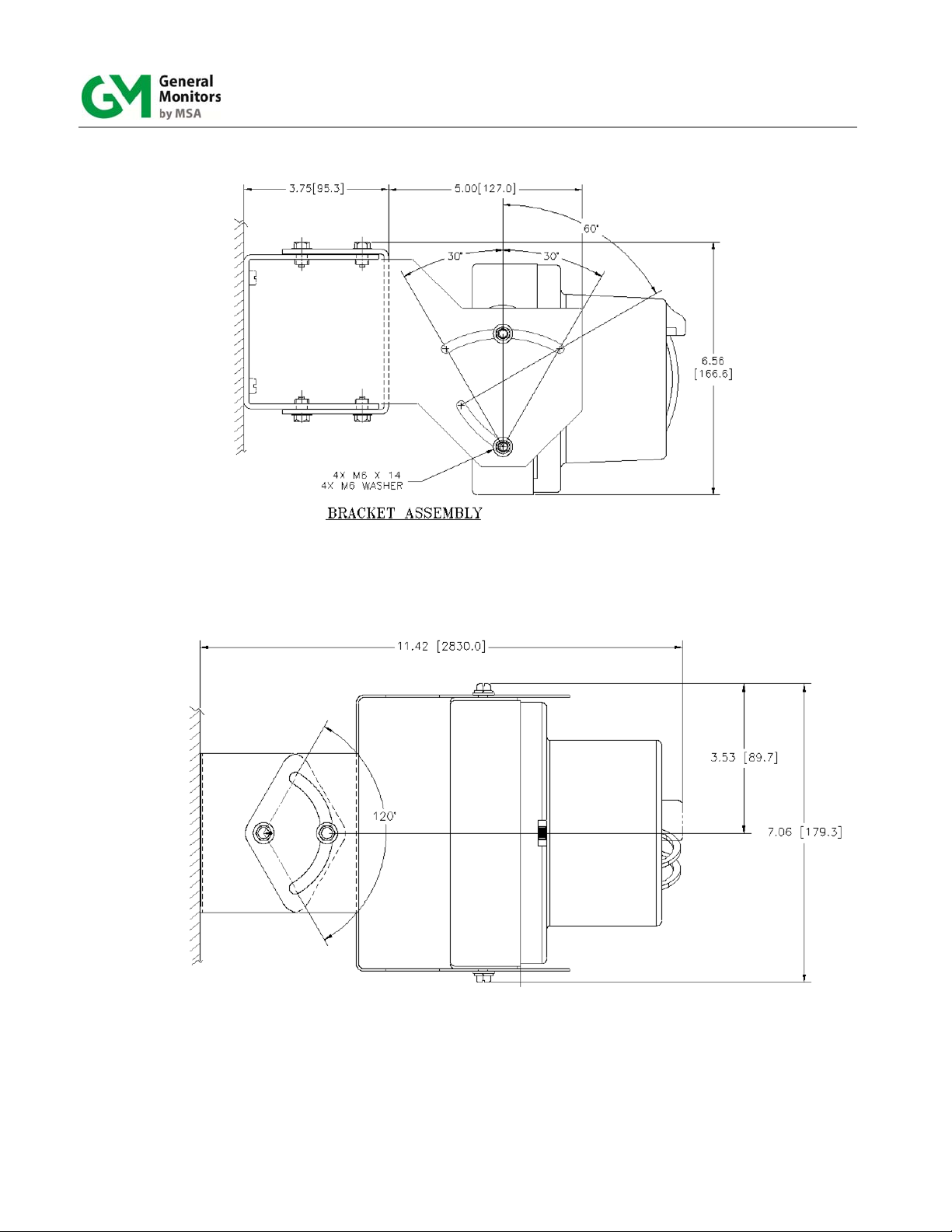
10.5.2 Mounting Bracket ........................................................................................................ 59
10.6 Storage ..................................................................................................................................... 59
10.7 Final Assembly ......................................................................................................................... 60
vi
Page 7

Models FL3100H/3101H
Table of Figures
Figure 1: P/N 961-004 Union Swivel Mounting Hardware ................................................................................. 1
Figure 2: P/N 71172 Side View Bracket Assembly ............................................................................................ 2
Figure 3: P/N 71172 Top View Bracket Assembly ............................................................................................ 2
Figure 4: P/N 71172 Rear View Bracket Assembly ............................................................................................ 3
Figure 5: Field Terminations ............................................................................................................................... 3
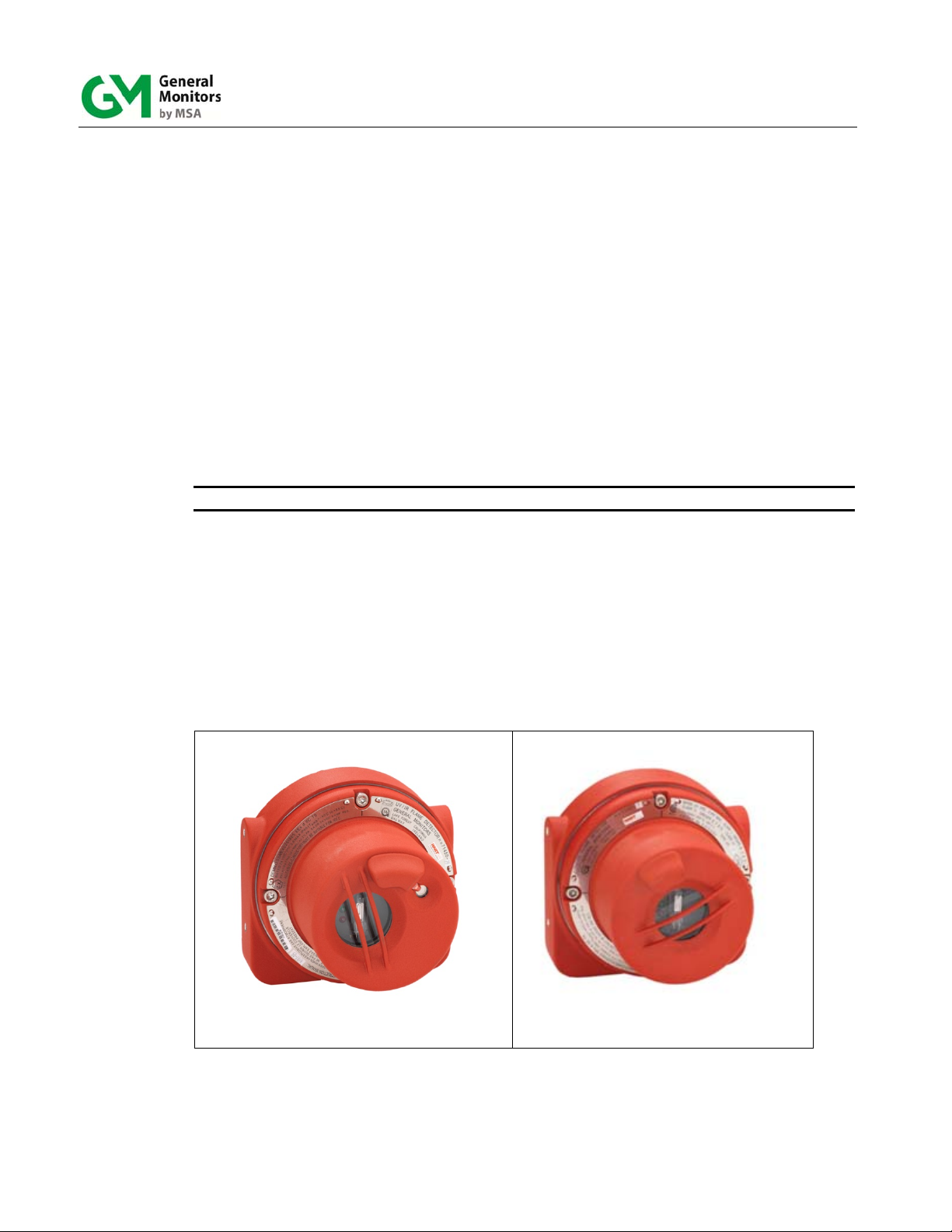
Figure 6: Model FL3100H ..................................................................................................................................... 7
Figure 7: Model FL3101H ..................................................................................................................................... 7
Figure 8: FL3100H (UV/IR) Field of View ............................................................................................................ 9
Figure 9: FL3100H (UV/IR) Hydrogen Flame Detector Field of View ............................................................. 10
Figure 10: FL3101H (UV) Field of View ............................................................................................................. 11
Figure 11: P/N 961-004 Swivel Elbow Drawing ................................................................................................ 12
Figure 12: P/N 71072 Side View Mounting Bracket Drawing .......................................................................... 13
Figure 13: P/N 71072 Top View Mounting Bracket Drawing ........................................................................... 13
Figure 14: P/N 71072 Rear View Mounting Bracket Drawing ......................................................................... 14
Figure 15: FL3100H and FL3101H Outline Drawing ........................................................................................ 15
Figure 16: FL3100H and FL3101H Outline Drawing ........................................................................................ 15
Figure 17: FL3100H and FL3101H Field Terminations .................................................................................... 16
Figure 18: Detector Housing and Base ............................................................................................................ 17
Figure 19: Terminal Block Operation ................................................................................................................ 17
Figure 20: Protection Circuits for Relay Contacts .......................................................................................... 18
Figure 21: DIP switch Location ......................................................................................................................... 25
Figure 22: UV and IR Windows .......................................................................................................................... 49
Figure 23: Spectral Response of UV and IR Detectors ................................................................................... 55
Figure 24: P/N 71450 FL3100H (UV/IR), Final Assembly ................................................................................ 60
Figure 25: P/N 71451 FL3101H (UV), Final Assembly .................................................................................... 61
vii
Page 8

Models FL3100H/3101H
Table of Tables
Table 1: TB2 Alarm Relay Connections ........................................................................................................... 18
Table 2: TB2 Warning Relay Connections ....................................................................................................... 19
Table 3: Fault Relay Connections ..................................................................................................................... 19
Table 4: Alarm Reset Terminal Connections ................................................................................................... 20
Table 5: Maximum Cable Requirements .......................................................................................................... 21
Table 6: Power Connections ............................................................................................................................. 21
Table 7: Maximum Cable Lengths for +24 VDC Supply .................................................................................. 21
Table 8: Connections for the Modbus Interface .............................................................................................. 22
Table 9: Connections for the Second Modbus Interface ................................................................................ 22
Table 10: Chassis Ground Connection ............................................................................................................ 22
Table 11: DIP Switch Options ............................................................................................................................ 25
Table 12: Data Format ........................................................................................................................................ 26
Table 13: Modbus Query Messages .................................................................................................................. 26
Table 14: Modbus Read Response Messages ................................................................................................. 27
Table 15: Modbus Write Query Message.......................................................................................................... 27
Table 16: Modbus Write Response Message ................................................................................................... 28
Table 17: Exception responses ......................................................................................................................... 29
Table 18: Exception Code Field ........................................................................................................................ 29
Table 19: Operational Mode Commands .......................................................................................................... 33
Table 20: Fire Status Mode ................................................................................................................................ 34
Table 21: Status/Error ........................................................................................................................................ 34
Table 22: Model Type ......................................................................................................................................... 35
Table 23: EEPROM Override .............................................................................................................................. 36
Table 24: Setting Options .................................................................................................................................. 37
Table 25: Comm 1 Baud Rate ............................................................................................................................ 37
Table 26: Comm 1 Data Format ......................................................................................................................... 38
Table 27: Remote Reset ..................................................................................................................................... 38
Table 28: Remote Alarm Test ............................................................................................................................ 39
Table 29: Clear COPM Faults Function ............................................................................................................ 39
Table 30: Comm 2 Baud Rate ............................................................................................................................ 42
Table 31: Comm 2 Data Format ......................................................................................................................... 42
Table 32: Event Logging Registry Table ......................................................................................................... 47
Table 33: Troubleshooting Table ...................................................................................................................... 52
Table 34: Locations ............................................................................................................................................ 53
viii
Page 9
Models FL3100H/3101H
Quick Start Guide
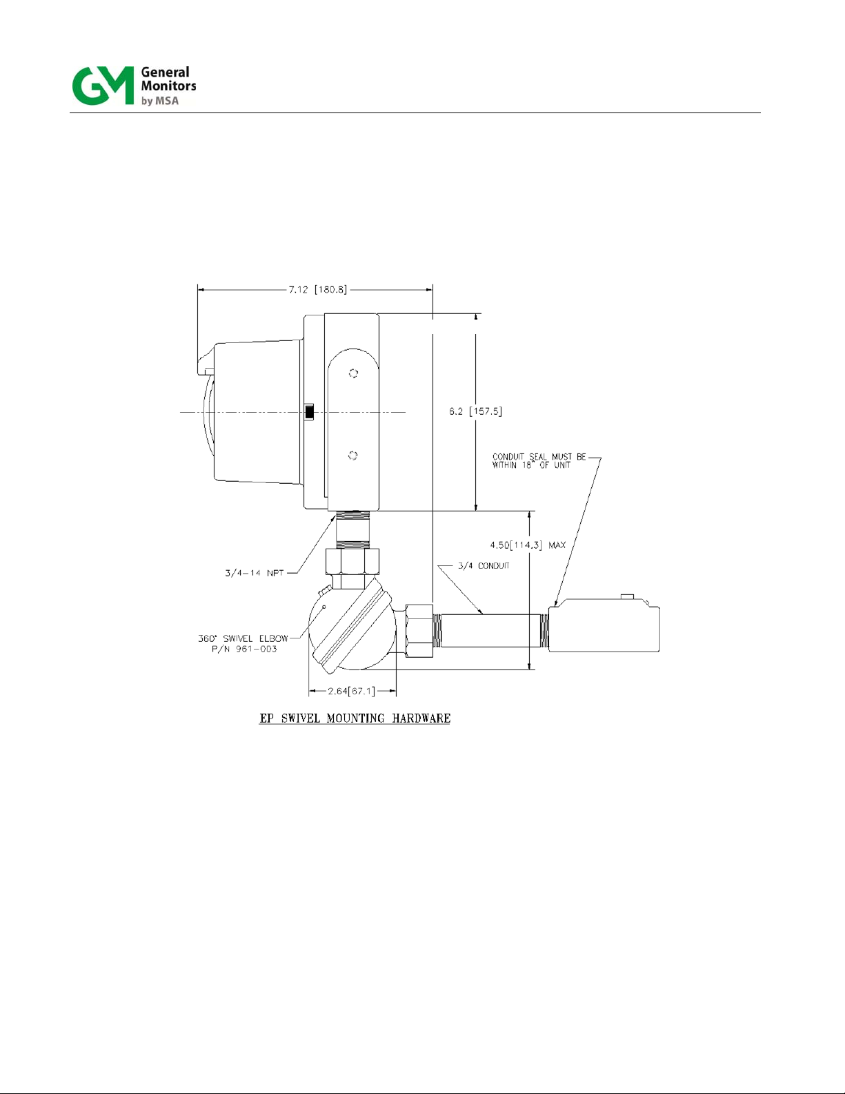
Mount and Wire the Detector
Pay special attention to the conduit seal entry (Canadian Electrical Code Handbook Part 1,
Section 18-154). Also, lithium based grease is applied to the O-ring seal between the backplate and housing, as additional protection to avoid water ingression into the housing. Mount
detector using swivel mount or mounting bracket hardware.
Figure 1: P/N 961-004 Union Swivel Mounting Hardware
1
Page 10
Models FL3100H/3101H
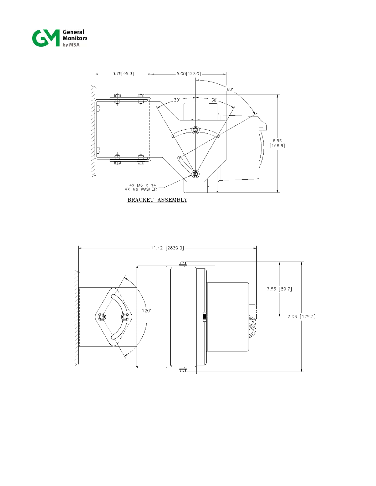
Figure 2: P/N 71172 Side View Bracket Assembly
Figure 3: P/N 71172 Top View Bracket Assembly
2
Page 11
Models FL3100H/3101H
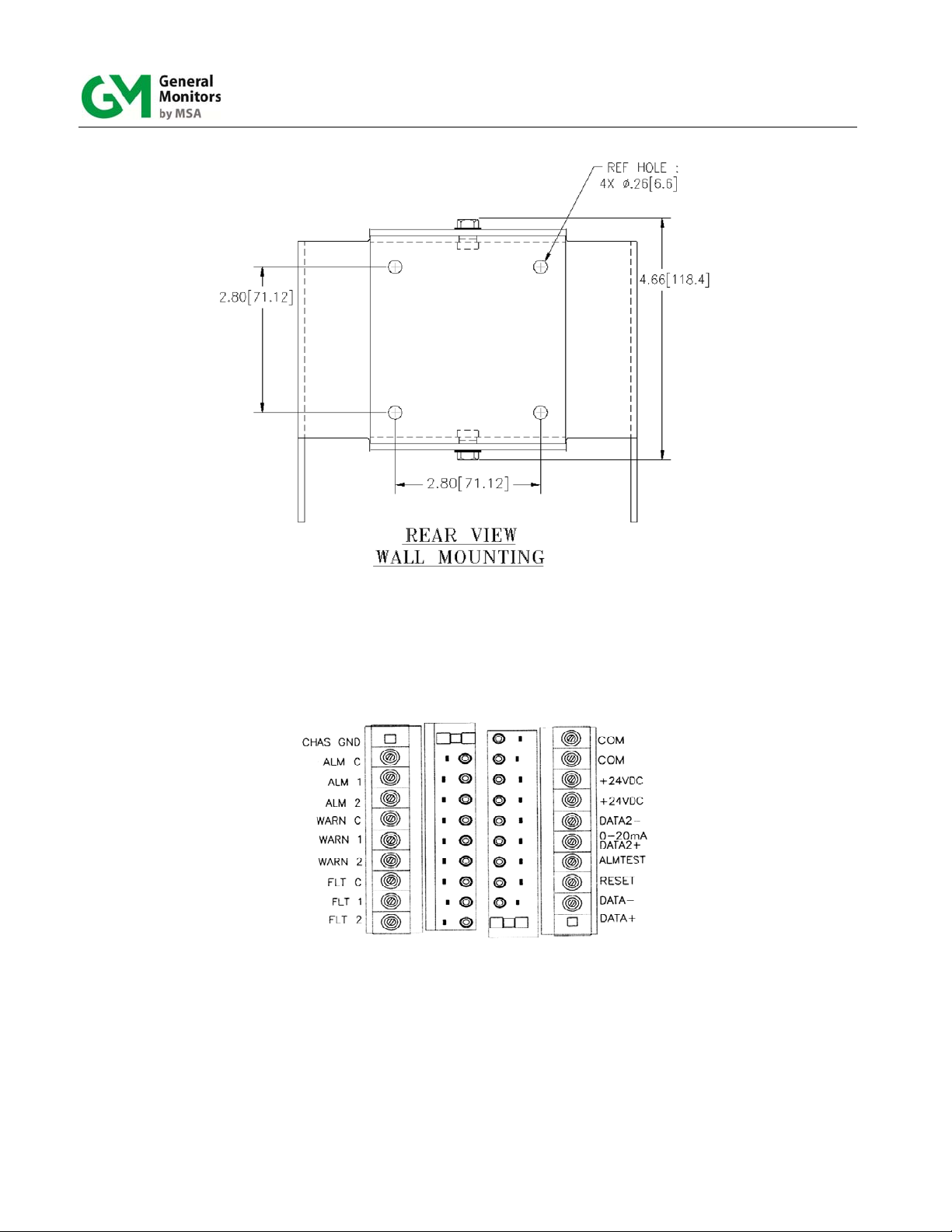
Figure 4: P/N 71172 Rear View Bracket Assembly
Term #
Terminal Block 2 Terminal Block 1
Term #
10
1
2
3
4
5
6
7
8
9
10
9
8
7
6
5
4
3
2
1
Figure 5: Field Terminations
3
Page 12

Models FL3100H/3101H
Apply Power to the Detector
Two light emitting diodes (LEDs) are visible through the UV window (the larger window on
UV/IR units). Immediately upon powering up the detector, the LEDs will start blinking alternately
- green and red in the two-color configuration and green, yellow, and red in the three-color
configuration. The flashing pattern lasts 10 seconds. Upon the detector entering the “Ready”
mode, the green LED will flash off 1 second, every 10 seconds. Section 10.2.6 (Three-color
Visual Indicators) describes the flashing scheme of the product configuration with three LEDs.
Testing the Detector Using the TL105
Test the integrity of your system by using the TL105 test lamp. The original configuration (i.e.
sensitivity and relay options) can be changed by using the “Switch Selectable Options” (Table
11) and then changing the dipswitch settings located on the bottom of the power board (SW1).
The instrument is now ready to operate. Please consult the manual for more information on the
instrument’s many features.
NOTE: If you have any problems in the set-up or testing of the detector, please refer to the
“Troubleshooting Section”, or call the factory direct.
Worldwide service is available by calling:
Lake Forest, California
(24 hr. service)
Houston, Texas
Ireland
Singapore
United Arab Emirates
United Kingdom
Toll Free: +1-800-446-4872
Phone: +1-949-581-4464
Fax: +1-949-581-1151
Phone: +1-281-855-6000
Fax: +1-281-855-3290
Phone: +353-91-751175
Fax: +353-91-751317
Phone: +65-6748-3488
Fax: +65-6748-1911
Phone: +971-4-294-3640
Phone: +44-1625-619583
Fax: +44-1625-619098
4
Page 13

Models FL3100H/3101H
1.0 Introduction
1.1 Protection for Life
General Monitors’ mission is to benefit society by providing solutions through industry leading
safety products, services, and systems that save lives and protect capital resources from the
dangers of hazardous flames, gases, and vapors.
This manual provides instruction for installing and operating General Monitors’ Models
FL3100H and FL3101H for UV/IR and UV Only Flame Detection. While the FL3100H/3101H is
easy to install and operate, this manual should be read in full and the information contained
herein understood before attempting to place the system in service.
The safety products you have purchased should be handled carefully and installed, and
maintained in accordance with the respective product instruction manual. Remember these
products are for your safety.
1.2 Special Warnings
Through engineering design, testing, manufacturing techniques, and rigid quality control,
General Monitors supplies the finest flame detection systems available. The user must
recognize his responsibility for maintaining the flame detection system in operational condition.
Installation and maintenance must be carried out by suitably skilled and competent personnel
only.
The FL3100H UV/IR and FL3101H UV only flame detectors contain components, which can be
damaged by static electricity. Special care must be taken when wiring the system, to ensure
that only the connection points are touched.
Special Conditions For Safe Use
This equipment uses an external non-metallic coating and may therefore generate an
ignition-capable level of electrostatic charge under certain extreme conditions. The
user should ensure that the equipment is not installed in a location where it may be
subjected to external conditions (such as high-pressure steam) which might cause a
build-up of electrostatic charge on non-conducting surfaces. Additionally, cleaning of
the equipment should be done only with a damp cloth.
In accordance with EN 60079-1:2014/ IEC 60079-1:Ed 7 Clause 11.3, the 4 x M6
housing retaining bolts are Class A2-70 304 Stainless Steel.
In accordance with EN 60079-1:2014/ IEC 60079-1:Ed 7 Clause 5.1, the flameproof
joints are not intended to be repaired.
1.3 System Integrity Verification
Commissioning Safety Systems
Before power up, verify wiring, terminal connections and stability of mounting for all integral
safety equipment including, but not limited to:
Power supplies
Control modules
Field detection devices
5
Page 14

Models FL3100H/3101H
Signaling / output devices
Accessories connected to field and signaling devices
After the initial application of power (and any factory specified warm-up period) to the safety
system, verify that all signal outputs, to and from devices and modules, are within the
manufacturers’ specifications. Initial testing should be performed per the manufacturers’
recommendations and instructions.
Proper system operation should be verified by performing a full, functional test of all component
devices of the safety system, ensuring that the proper levels of alarming occur.
Fault/Malfunction circuit operation should be verified.
Periodic Testing of Field Devices
Periodic testing should be performed per the manufacturers’ recommendations and
instructions. Testing procedures should include, but not be limited to:
Verify integrity of all optical surfaces and devices
For flame detectors, use the appropriate test lamp
When testing produces results outside of the manufacturers’ specifications, replacement of the
suspect device(s) should be performed as necessary.
Periodic System Verification
The following system verifications should be performed at least annually:
Verify wiring, terminal connections and stability of mounting for all integral safety equipment
including, but not limited to:
Power supplies
Control modules
Field detection devices
Signaling / output devices
Accessories connected to field and signaling devices
Proper system operation should be verified by performing a full, functional test of all component
devices of the detection system, ensuring that the proper levels of alarming occur.
Fault/Malfunction circuit operation should be verified.
Maintenance intervals should be independently established through a documented procedure,
including a maintenance log maintained by plant personnel or third party testing services.
6
Page 15
Models FL3100H/3101H
2.0 Product Description
2.1 General Description
Fire is usually manifested in heat (IR), smoke, light (visible), and flame (UV). Flame is the
gaseous region of a fire where vigorous combustion chain reactions take place. These
reactions emit radiation covering the Infrared, Ultraviolet and the Visible Spectral Regions.
The General Monitors’ Model FL3100H is an ultraviolet/infrared (UV/IR) flame detector (Figure
6). It detects the ultraviolet and infrared spectral regions of flame to produce a system which is
highly immune to false alarms caused by lightning, arc-welding, hot objects, and other sources
of radiation. The Model FL3101H is an ultraviolet (UV) flame detector (Figure 7). It only
responds to UV and has been optimized for speed of response.
Both units may be used with the General Monitors TA402A trip amplifier, FL802 controller, or
with other equipment, which accepts the 4 to 20 mA output. They may also be interfaced
directly with alarm/suppression devices or with switched input modules using integral relays. If
HART is used with the above controllers, you must use the special 1.25 mA to 20 mA mode.
NOTE: The Model FL802 is not CE Marked and, therefore, cannot be supplied to the EU.
The Models FL3100H and FL3101H features include:
Compact unitized design
Continuous optical path monitoring (COPM)
4-20 mA, alarm relays, and Modbus RTU RS-485 standard (Dual Modbus optional)
(HART optional)
Wide field of view
High false alarm immunity and visual indicators
Figure 6: Model FL3100H
7
Figure 7: Model FL3101H
Page 16

Models FL3100H/3101H
3.0 Installation
WARNING: Suitably skilled and competent personnel must carry out installation and
maintenance.
3.1 Tools Required
“T” Allen head wrench to remove detector head from detector base (included with flame
detector).
Flat head screwdriver maximum 3/16 in (5 mm) width for terminal block connections.
Adjustable wrench for conduit, or cable gland connections.
3.2 Choosing Product Locations
Several variables are involved in selecting the locations to install detectors to ensure proper
flame detection. There are no hard and fast rules defining the optimum location. Following are
some general suggestions that should be considered in regard to particular conditions at the
site where the unit(s) are being installed:
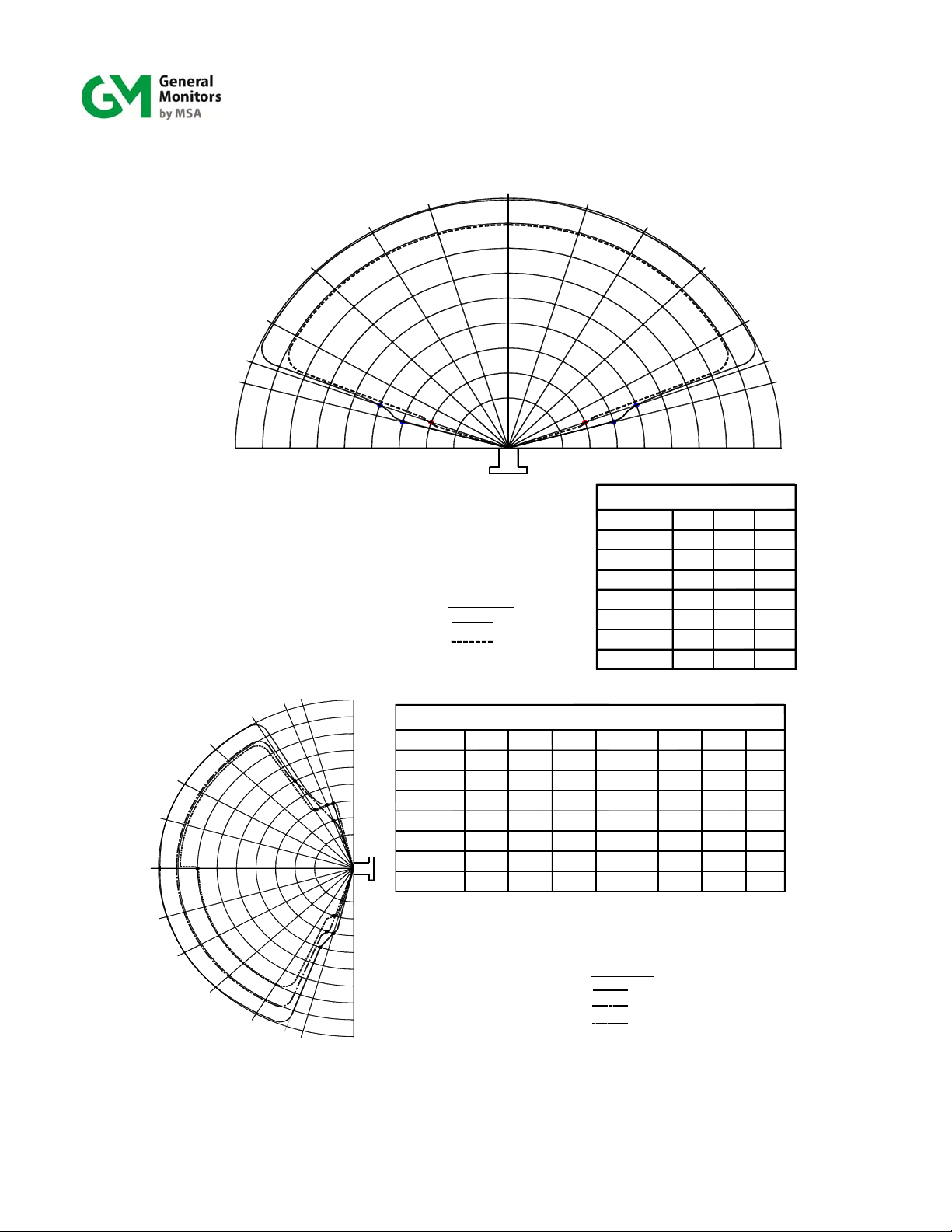
3.2.1 Detector Field of View
The FL3100H and FL3101H flame detectors have a maximum cone of vision of 120 and 140
maximum respectively. This cone has its vertex at the center of the detector (Figure 8 and
Figure 10).
3.2.2 Optical Sensitivity Range
The distance at which the detector will respond to a flame is a function of the intensity of that
flame. The maximum distance is 50ft (15.2m) for a heptane fire with a surface area of 1 sq. ft.
(0.093m2).
3.2.3 Environmental Factors
Mounting should be as free from shock and vibration as possible and convenient for visual
inspection and cleaning.
Detectors mounted in dirty atmospheric conditions will require frequent inspection, cleaning,
and sensitivity checking. Make sure the field-of-view of the detector is not obstructed by the
cover or nearby objects.
Observe the ambient temperature range for the specific model (Section 10.3.4). For outdoor
installations or other areas exposed to intense, direct solar radiation, the detector may reach
temperatures well above specifications. For these installations, a shade or cover may be
required to keep the detector temperature within specifications.
Avoid conditions that would allow ice build-up on the optical detector windows. Complete icing
over of the detector window(s) can result in fault conditions. Mount away from sources of
electrical noise where possible. A constant UV source detected by the unit will cause the
detector to go into FAULT after 9 – 10 minutes of exposure. The source must be removed or
the detector must be repositioned. (UV detectors can pick-up arc welding up to 2–3 miles
away). Users should be aware that any UV detector may be triggered by other sources of EMI,
for instance X-rays, sunlight, reflected sunlight, Gamma rays, lightning, arc welding, industrial
lighting, fluorescent lighting, etc., and due regard should be paid to the possible presence of
such radiation.
8
Page 17
Models FL3100H/3101H
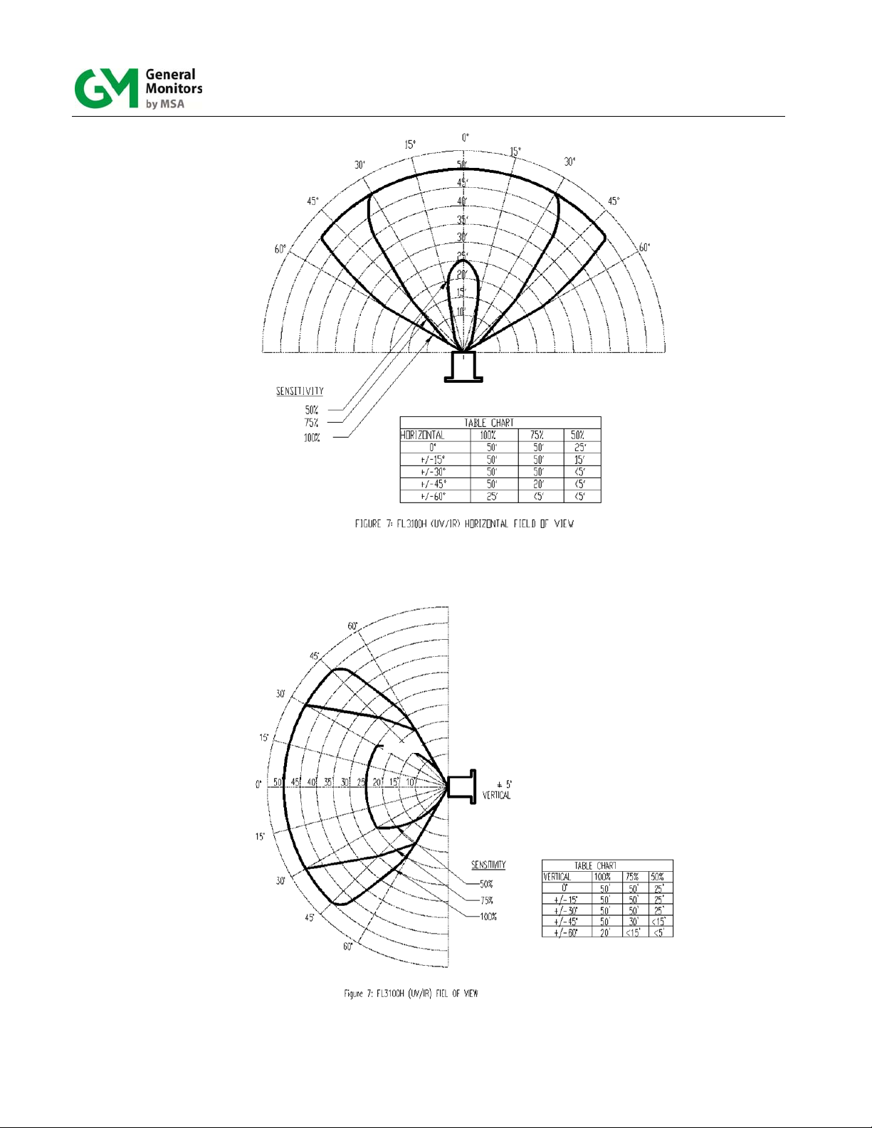
Figure 8: FL3100H (UV/IR) Field of View
9
Page 18
Models FL3100H/3101H
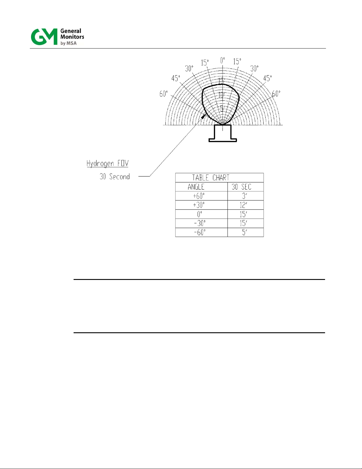
Figure 9: FL3100H (UV/IR) Hydrogen Flame Detector Field of View
NOTE: Response Times and Field of View data have been derived by testing the Model
FL3100H flame detector with a flame from a round 6 inch diameter burner. The
hydrogen gas was supplied from a high pressure tank via a reducing regulator, set to
12 psi. This produces a flame 6 inches in height. The FL3100H-Hydrogen detector can
be tested by the TL105 as far as 40 feet. These are typical values and different results
may occur depending on the variation of each fire.
NOTE: The FL3100H-Hydrogen detector is not FM approved.
10
Page 19
Models FL3100H/3101H
0°
75°
70°
60°
45°
30°
15°
50'
45'
40'
35'
30'
25'
20'
15'
10'
15°
30°
45°
60°
70°
75°
+15°
0°
-15°
+30°
'
0
5
(±5°)
HORIZONTAL
SENSITIVIT Y
100%
75%, 50%
+75°
+70°
+60°
+45°
'
'
'
'
'
'
5
0
0
5
3
3
4
4
'
5
2
'
0
5
0
2
1
1
VERTICAL
0°
- 15°
- 30°
- 45°
- 60°
- 70°
- 75°
100%
50'
50'
50'
50'
50'
25'
<20'
TABLE CHART
50%
75%
40'
45'
40'
45'
40'
45'
45'
40'
45'
<15'
<20'
<15'
<20'
TABLE CHART
0°
100%
50'
50'
50'
50'
50'
25'
20'
100%
50'
50'
50'
50' 30'
<20' <15'
HORIZONTAL
± 15°
± 30°
± 45°
± 60°
± 70°
± 75°
VERTICAL
0°
+ 15°
+ 30°
+ 45°
+ 60°
+ 70°
+ 75°
75%
45'
45'
45'
45'
45'
<15'
75% 50%
45'
45'
45'
45'50'40'
<15'20'
<20'
<20'
50%
45'
45'
45'
45'
45'
<15'
<15'<15'
45'
45'
45'
45'
20'
-30°
-45°
-60°
-70°
(±5°)
VERTICAL
-75°
SENSITIVITY
100%
75%
50%
Figure 10: FL3101H (UV) Field of View
11
Page 20
Models FL3100H/3101H
3.3 Mounting and Wiring
WARNING: The conduit entries should be sealed per the Canadian Electrical Code
Handbook (Part 1, Section 18-154) or NEC 500-3d. An additional benefit of
conduit seals is the prevention of water entering the housing through the
conduit entry.
WARNING: Unused cable entry holes must be sealed with an approved stopping plug.
Red caps supplied by GM are for dust protection only and must not be left
on the unit when installed.
The FL3100H/FL3101H flame detectors should be mounted pointing downward so that
dust/moisture will not accumulate on the optical window(s). The detector(s) should be
mounted in locations which will inhibit people or objects from obscuring the detector’s
cone of vision.
Detectors should be mounted such that the conduit or cable gland entries are
pointed downward. See above warning for conduit entries. For cable glands and
stopping plugs, the threads should be sealed with Castrol EP and boots fitted over
the cable gland to prevent water ingress at the cable-to-gland junction. Mounting
hardware should be used as shown in Figure 12, and Figure 13.The overall
dimensions of the detector and mounting hardware are shown in Figure 15 and
Figure 16.
NOTE: General Monitors does not recommend the use of cable shoes or crimps on any
junction box or housing wiring terminals. Poor crimping can cause a bad
connection when the unit experiences temperature variations.
Figure 11: P/N 961-004 Swivel Elbow Drawing
12
Page 21
Models FL3100H/3101H
Figure 12: P/N 71072 Side View Mounting Bracket Drawing
Figure 13: P/N 71072 Top View Mounting Bracket Drawing
13
Page 22

Models FL3100H/3101H
Figure 14: P/N 71072 Rear View Mounting Bracket Drawing
14
Page 23

Models FL3100H/3101H
Figure 15: FL3100H and FL3101H Outline Drawing
[139.7]
5.0[127.0]
6.2[157.5]
.75[19.1]
2X 3/4 NPT ENTRY
5.5
1.50[38.1]
4X M6 X 1
2.94[74.7]
6.2[157.5]
1.63[41.4]
.75[19.1]
1.67[42.4]
Figure 16: FL3100H and FL3101H Outline Drawing
15
Page 24

Models FL3100H/3101H
Figure 17: FL3100H and FL3101H Field Terminations
16
Page 25

Models FL3100H/3101H
Figure 18: Detector Housing and Base
Term #
10
Terminal Block 2 Terminal Block 1
1
2
3
4
5
6
7
8
9
Term #
10
9
8
7
6
5
4
3
2
1
Figure 19: Terminal Block Operation
The optional HART signal will be on pin TB1- 5
17
Page 26

3.3.1 Terminal Connections
Models FL3100H/3101H
All wire connections are made through the base entries to the terminal block (Figure 19). The
terminal block accepts 14 AWG to 22 AWG (2.1 to 0.3 mm
2
) stranded or solid core wire. Each
wire should be stripped to .25 in (.64 cm). To connect the wire to the terminal block, insert the
conductor into the connection space as shown in Figure 19 and tighten the corresponding
screw terminal. There are twenty terminal connections. The following pages contain
descriptions and specifications for each connection.
WARNING: Relay contacts must be protected against transient and over-voltage conditions
(Figure 20).
H
H
Figure 20: Protection Circuits for Relay Contacts
3.3.2 Terminal Block TB2 – Alarm Relay Connections
TB2
Position
2 C Common Common
3 1 Normally Closed Normally Open
4 2 Normally Open Normally Closed
These connections are for the SPDT ALARM relay. The ALARM output is time delayed for 2, 4,
8 or 10 seconds. This time delay can be set by Modbus, HART, or by Dipswitch. The ALARM
output can be normally energized or normally de-energized, latching or non-latching, and these
options are also set via can be set by Modbus, HART, or by Dipswitch (Section 4.4). For all
relay connections see Figure 20.
North American Approved Applications: The ALARM relay contact ratings are 8A @ 250 VAC
and 8A @ 30 VDC resistive max.
European Union (EU) Approved Applications: The ALARM relay contact ratings are 8A, 30 V
RMS/42.4 V peak or 8A @ 30 VDC resistive max.
Alarm
Relays
Relay Contact
(De-Energized)
Table 1: TB2 Alarm Relay Connections
H
H
Relay Contact
(Energized)
18
Page 27

Models FL3100H/3101H
3.3.3 Terminal Block TB-2 Warning Relay Connections
TB2
Position
5 C Common Common
6 1 Normally Closed Normally Open
7 2 Normally Open Normally Closed
These connections are for the SPDT WARN relay. The WARN output is immediate on the
FL3100H/FL3101H. The WARN output can be normally energized or normally de-energized,
latching or non-latching, and these options are also set via Modbus, HART, or by Dipswitch
(Section 4.4).
The WARN relay contact ratings are 8A @ 250VAC and 8A @ 24VDC.
CAUTION: Inductive loads (bells, buzzers, relays, etc.) on dry relay contacts must be clamped
Warn Relays
Table 2: TB2 Warning Relay Connections
down as shown in Figure 20. Unclamped inductive loads can generate voltage
spikes in excess of 1000 Volts. Spikes of this magnitude may cause false alarms
and contact damage.
Relay Contacts
(De-Energized)
Relay Contacts
(Energized)
North American Approved Applications: The WARN relay contact ratings are 8A @ 250 VAC
and 8A @ 30 VDC resistive max.
European Union (EU) Approved Applications: The WARN relay contact ratings are 8A, 30 V
RMS/42.4 V peak or 8A @ 30 VDC resistive max.
3.3.4 Fault Relay
These connections are for the SPDT FAULT relay. The FAULT output configuration is normally
energized and non-latching. This is the standard configuration and it cannot be changed. The
FAULT circuit will be activated during the time-out function, a low power or loss of power
condition, and during a failed COPM check. During these conditions the FAULT relays will deenergize and the analog output signal will drop to 0 mA (2 mA for COPM faults) for the duration
of the FAULT.
TB2
Position
8 C C C
9 1 Normally Closed Normally Open
10 2 Normally Open Normally Closed
North American Approved Applications: The FAULT relay contact ratings are 8A @ 250 VAC
and 8A @ 30 VDC.
European Union (EU) Approved Applications: The FAULT relay contact ratings are 8A, 30 V
RMS/42.4 V peak or 8A @ 30 VDC resistive max.
Fault
Relays
Relay Contacts
(De-Energized)
Table 3: Fault Relay Connections
Relay Contacts
(Energized)
19
Page 28

Models FL3100H/3101H
3.3.5 Alarm Reset Terminal
The RESET, when activated, returns a latched ALARM and/or WARN output that is no longer
valid, to its original state. For this RESET function, place one contact of a normally open
momentary switch to TB1 Terminal 3 and the other contact to DC COM (the detector’s
common). To activate, just press and release the switch.
TB1
Position
3 RESET
4 TEST
5 0-20 mA
Table 4: Alarm Reset Terminal Connections
By connecting one contact of a normally open, momentary switch, to TB1 Terminal 4 and the
other contact to TB1 Terminals 9 and 10 (DC COM), the user can test the alarm outputs of the
flame detector by activating this switch for two to ten seconds depending on the alarm time
delay setting. The Alarm Test will activate the WARN and ALARM relay outputs as well as the
appropriate analog output. The flame detector will remain in this state until the switch is
released. Note: This function is also available via Modbus and HART.
NOTE: The latching WARN and/or ALARM will have to be RESET manually. The Alarm Test
feature cannot be daisy chained between two or more FL3100H/FL3101H flame
detectors.
Relays
3.3.6 Analog Output
The 0 to 20 mA output is a current signal that corresponds to the following signals:
Condition Current Modbus HART (Normal) HART (Special)
START UP:
0 to 0.2 mA 3.5 ± 0.1 mA 1.25 ± 0.1 mA
FAULT:
COPM Fault:
Ready:
IR (FL3100H only):
UV (FL3100H only):
WARN:
ALARM:
When HART is selected, the output current changes to comply with the HART Foundation
requirements. The HART Foundation does not specify current below 3.5 mA. In normal HART
mode, the actual current does not go below 3.5 mA. Modbus reports the analog output as if
HART was not there, meaning it reports 2.0 mA for COPM. This allows users to use a constant
Modbus program. The digital HART reports the actual current. When the alarm or warning
20
0 to 0.2 mA 3.5 ± 0.1 mA 1.25 ± 0.1 mA
2.0 ± 0.1 mA 3.5 ± 0.1 mA 2.0 ± 0.1 mA
4.05 ± 0.05 mA 4.05 ± 0.05 mA 4.05 ± 0.05 mA
8.0 ± 0.1 mA 8.0 ± 0.1 mA 8.0 ± 0.1 mA
12.0 ± 0.1 mA 12.0 ± 0.1 mA 12.0 ± 0.1 mA
16.0 ± 0.1 mA 16.0 ± 0.1 mA 16.0 ± 0.1 mA
20.0 ± 0.1 mA 20.0 ± 0.1 mA 20.0 ± 0.1 mA
Page 29

Models FL3100H/3101H
relays are latched, the highest output current is also latched. The output current will return to
4.0 mA after the relay reset is activated via Modbus, HART, or remote switch.
The HART special mode allows the current to go down to 1.25 mA. The HART will still function.
This mode must be used with GMI’s products that rely on 2 mA output for COPM and 1.5 for
offline and zero for fault (TA402A).
NOTE: The maximum analog output load is 600 ohms, including wiring.
3.3.7 Cable Requirements
For interfacing with 250 ohm input impedance devices, the following maximum cable lengths
apply (maximum 50-ohm loop):
Cable
AWG
Run
Feet
Cable
2
mm
Run
Meters
14 9000 2.50 2750
16
5800
1.50 1770
18 3800 1.00 1160
20 2400 0.75 730
22 1700 0.50 520
Table 5: Maximum Cable Requirements
3.3.8 Power
The supply voltage range is 20 to 36 VDC at the detector (low voltage is detected at
approximately 18.5 VDC).
TB1
Position
7 +24 VDC
8 +24 VDC
9 COM
10 COM
Table 6: Power Connections
The following maximum cable lengths apply for a +24 VDC supply (maximum 20 ohm loop):
Cable
AWG
Run
Meters
14 1370 2.5 4500
16 715 1.5 2340
18 470 1.00 1540
20 300 0.75 970
22 205 0.50 670
Connection
Cable
2
mm
Run
Feet
Table 7: Maximum Cable Lengths for +24 VDC Supply
21
Page 30

Models FL3100H/3101H
3.3.9 Modbus Interface
The Modbus interface is used to either query the unit’s status or to configure the unit. See
Section 5.0 for detailed information on Modbus RTU Protocol.
TB1
Position
1 DATA +
2 DATA -
Table 8: Connections for the Modbus Interface
NOTE: If Dual Modbus output is ordered, then the 0-20 mA and HART output is not available
and the wiring terminals for the second Modbus channels are as follows:
TB1
Position
5 DATA2 +
6 DATA2 -
Table 9: Connections for the Second Modbus Interface
Connection
Connection
3.3.10 Chassis Ground
This connection is available for use in wiring that requires a connection to chassis ground. It is
recommended the chassis be grounded at all times.
TB2
Position
1 CHAS GND
Connection
Table 10: Chassis Ground Connection
3.3.11 Connection to Fire Cards/Panels
For detectors wired together for monitoring via standard fire cards, GM will factory-fit EOL and
alarm resistors. If this special option is required, please specify at time of order and provide the
following information:
Specify one or two resistors (i.e. alarm only, or alarm resistor and EOL).
Specify value of resistors.
Where detectors are used in conjunction with a GM Model IN042 card, values would be 470ohm alarm resistor and 5.6K EOL. The EOL resistors are onboard the IN042, selectable by
DIP-switches.
NOTE: Contact General Monitors or an authorized representative for further details.
European Union (EU) Approved Applications: Interconnecting cables must have an overall
screen or screen and armor. Cables BS5308 Part 2, Type 2, or equivalents are suitable. Note
that the terms ‘screen’ and ‘shield’ are equivalent for the purpose of this manual. The cable
armor must be terminated in a suitable cable gland at the detector to ensure a positive
electrical connection.
22
Page 31

Models FL3100H/3101H
3.3.12 Cable Termination in the Non-Hazardous Area
The cable armor must be connected to safety earth in the safe area.
The cable screen (drain wire) must be connected to an instrument earth in the safe
area.
The power supply OV return must be connected to an instrument earth in the safe
area.
The interconnecting cables should be segregated from power and other noisy cables.
Avoid proximity to cables associated with radio transmitters, welders, switch mode
power supplies, inverters, battery chargers, ignition systems, generators, switch gear,
arc lights and other high frequency or high power switching process equipment. In
general, maintain separation of at least 1m between instrument and other cables.
Greater separations are required where long parallel cable runs are unavoidable. Avoid
running instrument cable trenches close to lightning conductor earthing pits.
Complete all cable insulation testing before connecting the cable at either end.
WARNING: Under no circumstances should equipment be connected or disconnected when
under power. This is contrary to hazardous area regulations and may lead to
serious damage to the equipment. Equipment damaged in this manner is not
covered under warranty.
23
Page 32

Models FL3100H/3101H
4.0 Operation
4.1 Checklist
Prior to starting the system verify the following:
Inhibit any external devices, such as automatic extinguishing fire suppression systems
or others, which you do not want activated.
Verify that the DIP-switch settings are set for the desired configuration.
Verify that the unit is properly mounted. Ensure the conduit/cable gland entries are
pointed downward.
Verify the field of view for each detector covers the area intended for flame detection.
Verify that the wiring is correct.
Verify that the power supply is connected properly. The detector is powered by +24
VDC (20 to 36 VDC voltage range). The detector will output a low voltage fault at 18.5
VDC or below.
4.2 Start Up
To start up the system, apply power to the flame detectors. Each detector will begin its self-test
start up sequence. For the first 10 seconds, the unit will output 0 mA, the fault relay stays deenergized, and the green and red LED will flash alternately. Each is on for about 300 ms. After
this 10-second period, the unit will output 4 mA, the fault relay will energize, the red LED will
turn off, and the green LED will turn on constant and briefly flash off every 5 seconds. The dual
Modbus version does not have a current output.
NOTE: If you ordered unit with three-color LED option, please refer to section 10.2.6 “Three-
color Visual Indicators” for the LED status.
4.3 System Test
To test the system, use the General Monitors Test Lamp Model TL105 (Section 7.3.2).
4.4 User Selectable Options/Factory Defaults
All settings on the Models FL3100H and FL3101H are done via a DIP switch on the
Power/Relay Board or via Modbus or HART which will override the dipswitch settings. To set
these options, remove the detector head from the base assembly and locate the DIP switch
(Figure 21). On the DIP switch, ON/CLOSED means the switch is pushed in on the side labeled
ON or CLOSED (opposite the OPEN side). OFF/OPEN means the switch is pushed in on the
side with the number corresponding to the switch position or the side labeled OPEN. Refer to
Table 11 for the switch assignments. The settings for the WARN and ALARM outputs have
been covered in Section 3.3. The time delay specifies the amount of time a WARN condition
persists before an ALARM condition will occur. If the HART option is ordered the current you
desire must be selected (1.25 mA or 3.5 mA). Factory default is 3.5 mA to 20 mA. HART
current is only HART or Modbus selectable, not DIP switch selectable.
24
Page 33

Models FL3100H/3101H
Option Off On
1. 100% Sens – 1 ft2@ 50 ft 1, 2
2. 75% Sens – 1 ft2 @ 35 ft 2 1
3. 50% Sens – 1 ft2 @ 25 ft 1 2
4. 2 Second ALARM Time Delay 3 4
5. 4 Second ALARM Time Delay 3, 4
6. 8 Second ALARM Time Delay 4 3
7. 10 Second ALARM Time Delay 3, 4
8. ALARM non-latching 5
9. ALARM latching 5
10. WARN non-latching 6
11. WARN latching 6
12. ALARM normally energized 7
13. ALARM normally de-energized 7
14. WARN normally energized 8
15. WARN normally de-energized 8
Table 11: DIP Switch Options
Figure 21: DIP switch Location
25
Page 34

Models FL3100H/3101H
5.0 Modbus Interface
Standard FL3100H or FL3101H flame detectors include a single Modbus that is referenced as
Comm 1. A dual Modbus feature is optional, which includes two independent communications
channels referenced as Comm 1 and Comm 2.
NOTE: If the dual Comm option is ordered, the analog output and HART will not be available.
5.1 Baud Rate
The Baud Rate is a selectable setting via the Modbus communications interface. The
selectable baud rates are 19.2K, 9600, 4800, or 2400 bits per second.
5.2 Data Format
The Data Format is a selectable setting via the Modbus communications interface. The
selectable data formats are as follows:
Data Bits Parity Stop Bit Format
8 None 1 8-N-1
8 Even 1 8-E-1
8 Odd 1 8-O-1
8 None 2 8-N-2
Table 12: Data Format
5.3 Modbus Read Status Protocol (Query/Response)
5.3.1 Modbus Read Query Message
Byte Modbus Range Referenced to FL3100H / FL3101H
1st Slave
Address
2nd Function
Code
3rd Starting
Address Hi**
4th Starting
Address Lo**
5th No. of
Registers Hi
6th No. of
Registers Lo
7th CRC Lo 00-FF (Hex) CRC Lo Byte
8th CRC Hi 00-FF (Hex) CRC Hi Byte
*: Address 0 is reserved for broadcast mode and will not be supported at this time.
NOTE
1-247 * FL3100H / FL3101H ID (Address)
(X = 0 or 1 Model Type)
03 Read Holding Registers
00 Not Used by FL3100H / FL3101H
00-FF (Hex) FL3100H / FL3101H Commands
00 Not Used by FL3100H / FL3101H
01 No. of 16 Bit Registers
Table 13: Modbus Query Messages
NOTE**: Start Address can be a maximum of 247 Address Locations (0000-0x00F7)
26
Page 35

Models FL3100H/3101H
5.3.2 Modbus Read Response Message
Byte Modbus Range
1st Slave
Address
2nd Function
Code
3rd Byte Count 02 – FF (Hex) No. of Data Bytes
4th Data Hi 00-FF (Hex) FL3100H / FL3101H Hi Byte
5th Data Lo 00-FF (Hex) FL3100H / FL3101H Lo Byte
6th CRC Lo 00-FF (Hex) CRC Lo Byte
7th CRC Hi 00-FF (Hex) CRC Hi Byte
Table 14: Modbus Read Response Messages
NOTE: Address 0 is reserved for broadcast mode and will not be supported at this time.
* (Decimal)
1-247
03 or 04 Read Holding Registers
Referenced to FL3100H,
FL3100H1
FL3100H / FL3101H ID (Address)
Status Data
Status Data
5.4 Modbus Write Command Protocol (Query/Response)
5.4.1 Modbus Write Query Message
Byte Modbus Range
1st Slave Address
2nd Function Code 06 Preset Single Register
3rd Register Address
**
Hi
4th Register Address
Lo**
5th Preset Data Hi 00-FF (Hex) FL3100H / FL3101H Hi Byte
6th Preset Data Lo 00-FF (Hex) FL3100H / FL3101H Lo Byte
th
7
8th CRC Hi 00-FF (Hex) CRC Hi Byte
*: Address 0 is reserved for broadcast mode and will not be supported at this time.
NOTE
NOTE**: Start Address can be a maximum of 247 Address Locations (0000-0x00F7).
CRC Lo 00-FF (Hex) CRC Lo Byte
Table 15: Modbus Write Query Message
*
1-247
(Decimal)
00 Not used by FL3100H /
00-FF (Hex) FL3100H / FL3101H Commands
Referenced to FL3100H /
FL3101H
FL3100H / FL3101H ID
(Address)
FL3101H
Command Data
Command Data
27
Page 36

Models FL3100H/3101H
5.4.2 Modbus Write Response Message
Byte Modbus Range
1st Slave Address 1-247*
(Decimal)
2nd Function Code 06 Preset Single Register
3rd Register Address
Hi**
4th Register Address
Lo**
5th Preset Data Hi 00-FF (Hex) FL3100H / FL3101H Hi Byte
6th Preset Data Lo 00-FF (Hex) FL3100H / FL3101H Lo Byte
7th CRC Lo 00-FF (Hex) CRC Lo Byte
8th CRC Hi 00-FF (Hex) CRC Hi Byte
Table 16: Modbus Write Response Message
NOTE*: Address 0 is reserved for broadcast mode and is not supported at this time.
NOTE**: Start Address can be a maximum of 247 Address Locations (0000-0x00F7).
00 Not used by FL3100H / FL3101H
00-FF (Hex) FL3100H / FL3101H Commands
Referenced to FL3100H /
FL3101H
FL3100H / FL3101H ID (Address)
Command Data
Command Data
5.4.3 Function Codes Supported
Function Code 03 or 04 (Read Holding Registers) is used to read status from the slave unit.
Function Code 06 (Preset Single Register) is used to write a command to the slav e unit.
5.5 Exception Responses and Exception Codes
In a normal exchange, the master device sends a query to the FL3100H / FL3101H. The
FL3100H / FL3101H receives the query and returns a normal response to the master. If a
normal communications error occurs, there are 4 possible responses from the FL3100H /
FL3101H:
1. If the FL3100H / FL3101H does not recognize the query due to a communications
error, then no response is returned from the FL3100H / FL3101H and the master
device will eventually process a timeout condition for the query.
2. If the FL3100H / FL3101H receives the query, but detects a communication error
(CRC, etc.), then no response is returned from the FL3100H / FL3101H and the master
device will eventually process a timeout condition for the query.
3. An exception code is returned when the FL3100H / FL3101H receives the query
without a communications error, but cannot process it due to reading or writing to a
non-existent or illegal Function Code, Illegal Command Starting Address or Register
Address, or Illegal Data Value. The exception response message has two fields that
differentiate it from a normal response. See the next section for more information.
28
Page 37

Models FL3100H/3101H
5.5.1 Exception Responses
Byte Modbus Range
1st Slave Address 1-247* (Decimal) FL3100H / FL3101H ID (Address)
2nd Function Code 83 or 86 (Hex) MSB is set with Function Code
3rd Exception Code 01 - 06 (Hex) Appropriate Exception Code (See
4th CRC Lo 00-FF (Hex) CRC Lo Byte
5th CRC Hi 00-FF (Hex) CRC Hi Byte
Table 17: Exception responses
5.5.1.1 Exception Code Field
In a normal response, the FL3100H / FL3101H returns data and status in the data field,
requested in the query from the master. In an exception response, the FL3100H / FL3101H
returns an exception code in the data field, which describes the condition that caused the
exception. Below is a list of exception codes that are supported by the FL3100H / FL3101H:
Code Name Description
01 Illegal Function The function code received in the query is not an
allowable action for the FL3100H / FL3101H.
02 Illegal Data Address The data address received in the query is not an
allowable address for the FL3100H / FL3101H.
03 Illegal Data Value A value contained in the query data field is not an
allowable value for the FL3100H / FL3101H.
04 Slave Device Failure An unrecoverable error occurred while the
FL3100H / FL3101H was attempting to perform the
requested action.
05 Acknowledge The FL3100H / FL3101H has accepted the request
and is processing it, but a long duration of time will
be required. This response is returned to prevent a
timeout error from occurring in the master.
06 Device Busy The FL3100H / FL3101H is engaged in processing
a long-duration program command. The master
should retransmit the message later when the slave
is free.
Referenced to FL3100H /
FL3101H
below)
Table 18: Exception Code Field
29
Page 38

Models FL3100H/3101H
5.6 Command Register Locations
5.6.1 Operational Mode Commands
See section number listed below and reference Section 5.7 for details of each register.
NOTE: The FL3100H has Modbus error reporting. The optional dual Modbus has error
reporting for each channel. It can also provide simultaneous block mode.
R - indicates Read Only Access R/W - indicates Read/Write Access
Parameter Function Type Scale Access
Analog 0-20 mA Current Output Value 16-Bit R 0000 40001
Mode Indicates Fire Status Mode Value (0-11) R 0001 40002
Status/Error Indicates Error Bit 16-Bit R 0002 40003
UV/IR Only Indicates Detection of UV
Only or IR Only (FL3100H
only)
Model Type Identifies the Model
FL3100H / FL3101H
Software
Rev
COPM Fault UV/IR COPM Fault Bit 2-Bit R 0006 40007
Override Override Dipswitch Settings Bit 1-Bit R/W 0007 40008
Options Indicates Unit Options Bit 8-Bit R/W 0008 40009
Comm 1
Address
Not Used 000A 40011
Comm 1
Baud Rate
Comm 1
Data Format
UV
Sig Count
IR
Sig Count
UV Fault
Total
IR
Fault Total
Remote
Reset
Indicates the Software
Revision
Unit Address Decimal
Baud Rate
(2400, 4800, 9600,19.2K)
Data Format
(8N-1, 8E-1, 8O-1, 8N-2)
Indicates No. of UV Signal
Pulses within 500 ms
Indicates No. of IR Signal
Pulses within 500 ms
Indicates Total No. of UV
COPM Faults
Indicates Total No. of IR
COPM Faults
Remotely Resets the Alarm
and Warn Relays
Bit 2-Bit R 0003 40004
Decimal 310X R 0004 40005
ASCII 2-Char R 0005 40006
(1-247)
Hex
Value (0-3) R/W 000B 40012
Value (0 - 3) R/W 000C 4001 3
Value 16-Bit R 000D 40014
Value 16-Bit R 000E 40015
Value 16-Bit R 000F 40016
Value 16-Bit R 0010 40017
Bit 1-Bit R/W 0011 40018
(01F7)
R/W 0009 40010
REG
Addr
Master
I/O
Addr
Refer to
Section
30
Page 39

Models FL3100H/3101H
Parameter Function Type Scale Access
Remote
Alarm Test
Clear
COPM
Faults
NOT Used 0014 40021
Serial
Number
Serial
Number
NOT Used 0017-
Optional
HART
All “1” or “0” HART Test 0 off 1, 2 Bit 2 Bit R/W 001E 40031
Not Used 001F 40032
Comm 1
Register
errors
Comm 1
Bus Activity
Rate %
Comm 1
Function
Code Errors
Comm 1
Starting
Address
Errors
Comm 1
Total
Receive
Errors
Comm 1
RXD CRC
Errors
Comm 1
RXD CRC
Errors
Comm 1
Overrun
Errors
Remotely Activates Alarm
Test
Clears UV/IR COPM Fault
Counters
Serial Number Upper Value 16 bit R 0015 40022
Serial Number Lower Value 16 bit R 0016 40023
HART Enable Bit 1 bit R/W 001D 40030
Total # of Register Errors
Bus Activity Rate in %
Of this Addressed Node vs.
Other Addressed Nodes
Total # of Function Code
Errors
Total # of Starting
Addresses
Errors
Total # of Comm 1
Receive Errors
Total # of RXD CRC
Errors
Total # of RXD CRC
Errors
Total # of Overrun Errors
Bit 1-Bit R/W 0012 40019
Bit 1-Bit R/W 0013 40020
Value 16-Bit R 0020 40033
Decimal
Hex
Value 16-Bit R 0022 40035
Value 16-Bit R 0023 40036
Value 16-Bit R 0024 40037
Value 16-Bit R 0025 40038
Value 16-Bit R 0026 40039
Value 16-Bit R 0027 40040
(0100%)
(0-64)
R 0021 40034
REG
Addr
1C
Master
I/O
Addr
40024-
40029
Refer to
Section
31
Page 40

Models FL3100H/3101H
Parameter Function Type Scale Access
Comm 1
Parity
Errors
Comm 1
Framing
Errors
Comm 1
UART errors
Comm 1
Total
Receive
Errors
Comm 1
Clear UART
Comm1
Clear Stats
HART
Current
Range
Comm 2
Address
Total # of Parity Errors Value 16-Bit R 0028 40041
Total # of Framing
Errors
Total # of UART errors Value 16 Bit 002A 40043
Total # of Comm 1
Receive Errors
Clear UART errors Bit 1-Bit R/W 002C 40045
Clear Comm Stats Bit 1-Bit R/W 002D 40046
3.5 ma to 20 ma
1.25 ma to 20 ma
Unit Address Decimal
Value 16-Bit R 0029 40042
Value 16-Bit R 002B 40044
Bit 1-Bit R/W 002E 40047
Hex
(1-247)
(01-F7)
R/W 002F 40048
REG
Addr
Master
I/O
Addr
Refer to
Section
Comm 2
Baud
Rate
Comm 2
Data
Format
Not Used 0032 40051
Input
Voltage
Voltage at
the alarm
input
Voltage at
the Reset
input
The position
of the dip
switch
Not used 0037
Indicates present Baud Rate
(2400, 4800, 9600, 19.2K)
Indicates present Data
Format
(8N-1, 8E-1, 8O-1, 8N-2)
Indicates the 24 volts Value 16-Bit R 0033 40052
Indicates alarm test input
voltage
Indicates reset input voltage Value 16-Bit R 0035 40054
Dip Switch Data Bits 16-Bit R 0036 40055
Value (0-3) R/W 0030 40049
Value (0-3) R/W 0031 40050
Value 16-Bit R 0034 40053
40056
003F
40064
32
Page 41

Models FL3100H/3101H
Parameter Function Type Scale Access
EVENT
LOGGING
USER
INFO
Comm 2
Register
errors
Comm 2
Bus Activity
Rate %
Comm 2
Function
Code Errors
Comm 2
Starting
Address
Errors
Comm 2
Total
Receive
Errors
Comm 2
RXD CRC
Errors
Comm 2
RXD CRC
Errors
Comm 2
Overrun
Errors
Comm 2
Parity
Errors
Comm 2
Framing
Errors
Comm 2
UART errors
Not Used 0083 40132
Comm 2
Clear UART
Comm2
Clear Stats
Event logging
See Section 6.0
User Information Value 16-Bit R/W 0068
Total # of Register Errors
Bus Activity Rate in %
Of this Addressed Node vs.
Other Addressed Nodes
Total # of Function Code
Errors
Total # of Starting
Addresses
Errors
Total # of Comm 2
Receive Errors
Total # of RXD CRC
Errors
Total # of RXD CRC
Errors
Total # of Overrun Errors
Total # of Parity Errors Value 16-Bit R 0080 40129
Total # of Framing
Errors
Total # of UART errors Value 16-Bit R 0082 40131
Clear UART errors Bit 1-Bit R/W 0084 40133
Clear Comm Stats Bit 1-Bit R/W 0085 40134
Value 0040
Value 16-Bit R 0078 40121
Decimal
Hex
Value 16-Bit R 007A 40123
Value 16-Bit R 007B 40124
Value 16-Bit R 007C 40125
Value 16-Bit R 007D 40126
Value 16-Bit R 007E 40127
Value 16-Bit R 007F 40128
Value 16-Bit R 0081 40130
16-Bit R 0079 40122
REG
Addr
0067
0077
Master
I/O
Addr
40065
40104
40105
40120
Refer to
Section
Table 19: Operational Mode Commands
33
Page 42

Models FL3100H/3101H
5.7 FL3100H / FL3101H Operational Mode Command Register
Details
5.7.1 Analog (00H)
A read returns a value which is proportional to the 0-20 mA output current. The current is based
on a 16-bit value. The master scaling is 0-65535 decimal, which corresponds to the FL3100H /
FL3101H scaling which is 0-20 mA.
5.7.2 Mode (01H)
A read returns the fire status mode of the FL3100H / FL3101H.
Mode Decimal Value
Power-up Delay 1
Warn Non-latching Only 2
Warn and Alarm Non-Latching 3
Warn Latching Only 4
Alarm Latching Only 5
Warn and Alarm Latching 6
Ready State (No Fire) 7
UV Only Fire (FL3100H Model Only) 8
IR Only Fire (FL3100H Model Only) 9
Alarm Test 10
COPM Fault Detected 11
Table 20: Fire Status Mode
5.7.3 Status/Error (02H)
A read returns the errors that are occurring, which are indicated by bit position.
Byte Function Bit Position Hex
Reset Line Shorted 8 0x8000
UV 10 Minute 7 0x4000
Not Used 6 0x2000
High
Low
Not Used 5 0x1000
Output Current Fault 4 0x0800
Not Used 3 0x0400
Not Used 2 0x0200
Not Used 1 0x0100
Flash Checksum 8 0x0080
EEPROM Checksum 7 0x0040
RAM Test 6 0x0020
Low Line Voltage Check 5 0x0010
UV COPM 4 0x0008
IR COPM 3 0x0004
Not Used 2 0x0002
Internal Voltage 1 0x0001
Table 21: Status/Error
34
Page 43

Models FL3100H/3101H
5.7.4 Faults
Reset Line Shorted: The FL3100H sees a continuous short. Check TB1-3.
UV 10 Minute: The UV detector sees a constant source of UV. Check for welding, arcing, very
bright lights or other sources of UV.
Output Current Fault: There is an error in the current output circuit. Return for service.
Flash Checksum: The main program memory is not functioning properly. Return for service.
EEPROM Checksum: There are two sources of EEPROM error. One is recoverable, the
other must be sent back to the factory. The recoverable error can be reset by turning the
power on and off. The user then must check all the FL3100H options; Latch/Non-latch,
Energized/De-energized, Baud rate etc.
RAM Test: The memory is not functioning. Return for service.
Low Line Voltage Check: The input voltage is low. Check the input voltage with a meter or
via HART or Modbus.
UV COPM: The UV window needs to be cleaned.
IR COPM: The IR window needs to be cleaned.
Internal Voltage: The FL3100H monitors various internal voltages. Return for service.
5.7.5 UV/IR Only (03H)
A read indicates the detection of UV Only or IR only when using the UV/IR Model FL3100H.
UV Only Detected = 01 (Lo Data Byte)
IR Only Detected = 02 (Lo Data Byte)
The High Data Byte is Not Used.
5.7.6 Model Type (04H)
A read returns the Decimal Value 3100 or 3101, which identifies each particular type of unit by
model number.
Model Configuration HART ID Modbus ID
FL3100 Standard UV/IR NA 3100 0x0C1C
FL3100H Standard UV/IR 0x90 3103 0x0C1F
FL3100H Long Range 0x90 3106 0x0C22
FL3100H Hydrogen 0x90 3105 0x0C21
FL3101 Standard UV NA 3101 0x0C1D
FL3101H UV only 0x90 3104 0x0C20
Table 22: Model Type
35
Page 44

Models FL3100H/3101H
5.7.7 Software Revision (05H)
A read returns the software revision of the FL3100H / FL3101H in 2 ASCII characters. (REV “A”
appears as a blank and the letter A).
5.7.8 COPM Fault (06H)
A read returns the type of Continuous Optical Path Monitoring (COPM) Fault which is an UV
COPM Fault or an IR COPM Fault, or both. The UV COPM and/or the IR COPM Faults indicate
that the UV and/or IR windows are dirty and need to be cleaned, or that there is a hardware
problem with the UV and/or IR detection circuitry.
UV COPM Fault = 01 (Lo Data Byte)
IR COPM Fault = 02 (Lo Data Byte)
The High Data Byte is Not Used.
5.7.9 EEPROM Override (07H)
A read indicates the status of the EEPROM Override bit. A write command changes the state of
the EEPROM Override bit. When the EEPROM Override bit is enabled, the options for the
Detector Sensitivity, Relay Delay, Relay Latching/Non-Latching and Relay Energized/NonEnergized features are now controlled by the data stored in the EEPROM and are no longer
controlled by the 8-position DIP switch located on the bottom of the Power/Relay Board. When
the EEPROM Override bit is disabled the options are under the control of the 8-position DIP
switch. The EEPROM Override bit is located in the LSB of the Low Data Byte and the High
Data Byte is not used.
Function Bit (LSB) Access
Enable 1 Read/Write
Disable 0 Read/Write
Table 23: EEPROM Override
NOTE: By grounding the ALARM TEST input during power-up cycle (approximately 10
seconds), the FL3100H / FL3101H will disable the EEPROM Override and set the Bit =
0, thus enabling the 8-position DIP switch.
5.7.10 Options (08H)
A read returns the status of the settings for the Detector Sensitivity, Relay Delay, Relay
Latching/Non-Latching and Relay Energized/Non-Energized features either from the Options
Dipswitch or the EEPROM depending on the setting of the EEPROM Override bit listed above.
A write command changes the settings for the EEPROM only when the EEPROM Override bit
is set.
EXCEPTION - If an attempt to change the EEPROM Options is made while the EEPROM
Override bit is not set, then the unit shall return an Exception Code 01 (Illegal Function).
36
Page 45

Models FL3100H/3101H
These functions are indicated on the Low Data Byte and the High Data Byte is not used.
Function Bit
Position
Warn Energized 8 (MSB)
Alarm Energized 7
Warn Latched 6
Alarm Latched 5
10 8 4 2 Time Delay in Seconds
Alarm Time Delay 2 4 1 0 0 1 Read/Write
Alarm Time Delay 1 3 1 1 0 0 Read/Write
100 75 50 % Sensitivity
Sensitivity 2 2 0 0 1 Read/Write
Sensitivity 1 1 (LSB) 0 1 0 Read/Write
1 = Energized
0= Non-Energized
1 = Energized
0= Non-Energized
1 = Latched
0 = Non-Latched
1 = Latched
0 = Non-Latched
Table 24: Setting Options
Conditions Access
Read/Write
Read/Write
Read/Write
Read/Write
5.7.11 Comm 1 Address (09H)
A read returns the Comm 1 address of the FL3100H / FL3101H. A write changes the address
to the requested address. The range of the address is 1 to 247 (01 to F7 Hex). After the
address has been changed to the slave unit, the Modbus communications will cease because
the address has changed; therefore the master will have to change its query address to the
slave’s new address in order to restart the communications.
EXCEPTION - If an illegal data value is entered (must be between 1, 0x00F7), then the
Exception Code 03 (Illegal Data Value) is returned.
NOTE: By grounding the RESET input during power-up cycle (approximately 10 seconds), the
FL3100H / FL3101H Address will default to 1.
5.7.12 Comm 1 Baud Rate (0BH)
A read returns the Comm 1 baud rate of the FL3100H / FL3101H. A write changes the baud
rate to the requested baud rate. After the baud rate has been changed to the addressed unit,
the Modbus communications will cease because the baud rate has changed; therefore the
master will have to change its baud rate to the slave’s new baud rate in order to restart the
communications.
Baud Rate Low Data Byte Access
19.2K 03 Read/Write
9600 02 Read/Write
4800 01 Read/Write
2400 00 Read/Write
Table 25: Comm 1 Baud Rate
This function is indicated on the Low Data Byte (the High Data Byte is not used).
EXCEPTION - If an illegal data value is entered which is not listed above, then the Exception
Code 03 (Illegal Data Value) is returned.
NOTE: By grounding the RESET input during power-up cycle (approximately 10 seconds), the
FL3100H, and FL3101H Baud Rate will default to 19.2K.
37
Page 46

Models FL3100H/3101H
5.7.13 Comm 1 Data Format (0CH)
A read returns the Comm 1 data format of the FL3100H / FL3101H. A write changes the data
format to the requested data format. After the data format has been changed to the addressed
unit, the Modbus communications may cease or start producing Comm errors because the data
format has changed; therefore the master will have to change its data format to the slave’s new
data format in order to restart or provide proper communications.
Data Parity Stop Format
8 None 1 8-N-1 00 Read/Write
8 Even 1 8-E-1 01 Read/Write
8 Odd 1 8-O-1 02 Read/Write
8 None 2 8-N-2 03 Read/Write
Table 26: Comm 1 Data Format
This function is indicated on the Low Data Byte and the High Data Byte is not used.
EXCEPTION - If an illegal data value is entered which is not listed above, then the Exception
Code 03 (Illegal Data Value) is returned.
NOTE: By grounding the RESET input during power-up cycle (approximately 10 seconds), the
FL3100H, and FL3101H Data Format will default to 8-N-1.
Low Data
Byte
Access
5.7.14 UV Signal Count (0DH)
A read indicates the number of UV Signal Counts that have occurred within 500 ms, which is
the time duration that is required to detect a fire in the UV spectrum.
5.7.15 IR Signal Count (0EH)
A read indicates the number of IR Signal Counts that have occurred within 500 ms which is the
time duration that is required to detect a fire in the IR spectrum.
5.7.16 UV Fault Total (0FH)
A read indicates the total number of UV COPM Faults for an indefinite period of time until the
Clear COPM Fault command is activated. The maximum count is 65535 and then the counter
will rollover to zero and begin counting again.
5.7.17 IR Fault Total (10H)
A read indicates total number of IR COPM Faults for an indefinite period of time until the Clear
COPM Fault command is activated. The maximum count is 65535 and then the counter rolls
back to zero and begins counting again.
5.7.18 Remote Reset (11H)
Writing a 1 to the bit activates the Remote Reset function that resets the Alarm and Warn
Relays. The function is active momentarily and resets automatically after being used.
Function Bit (LSB) Access
Enable 1 Read/Write
Disable 0 Read/Write
Table 27: Remote Reset
EXCEPTION - If an illegal data value is entered which is not listed above, then the Exception
Code 03 (Illegal Data Value) is returned.
38
Page 47

Models FL3100H/3101H
5.7.19 Remote Alarm Test (12H)
Writing a 1 to the bit activates the Remote Alarm Test function, which activates the Warn and
Alarm relay and causes the Analog current to show warn then alarm. Once the Alarm Test is
complete, the Remote Alarm Test function should be disabled by writing a zero to the Remote
Alarm Test and then resetting the Alarm and Warn relays by writing a one to the Remote Reset
(referenced above).
Function Bit (LSB) Access
Enable 1 Read/Write
Disable 0 Read/Write
Table 28: Remote Alarm Test
EXCEPTION - If an illegal data value is entered which is not listed above, then the Exception
Code 03 (Illegal Data Value) is returned.
5.7.20 Clear COPM Faults (13H)
Writing a 1 to the bit activates the Clear COPM Faults function that resets both the UV and IR
COPM faults. The function is active momentarily and resets automatically after being used.
Function Bit (LSB) Access
Enable 1 Read/Write
Disable 0 Read/Write
Table 29: Clear COPM Faults Function
EXCEPTION - If an illegal data value is entered which is not listed above, then the Exception
Code 03 (Illegal Data Value) is returned.
5.7.21 Serial Number (15/16H)
The serial number is a 32-bit word but the value is only 23 bits long. The upper bits are always
zero. This is done to keep the same serial number as the HART serial number. Address 0x16
contains the lower part of the number and address 0X15 contains the upper part.
5.7.22 HART Enable (1D)
This command enables or disables HART. A “0” is HART disabled. A “1” is HART Enabled.
This is an option that must be ordered. If HART is not installed, an exception will be returned.
5.7.23 HART Test (1E)
This command is used to test the HART output. It produces constant zeros or constant ones on
the HART output. This is only available if the HART option was purchased.
Code Results
0 Normal
1 Constant ones
2 Constant zeros
39
Page 48

Models FL3100H/3101H
5.7.24 Not Used (1F)
5.7.25 Comm 1 Total Illegal number of registers Errors (20H)
A read indicates the total illegal number of registers errors on the Modbus. The maximum count
is 65535 and then the counter rolls over to zero and begins counting again.
5.7.26 Comm 1 Bus Activity Rate % (21H)
A read indicates the Comm 1 Bus Activity Rate in percent of this Slave's addressed node
versus other addressed nodes. Range of this value is in hex (0-64), which translates to decimal
(0-100%).
5.7.27 Comm 1 Function Code Errors (22H)
A read indicates the number of Comm Function Code Errors that occurred in the slave device.
The maximum count is 65535 and then the counter rolls over to zero and begins counting
again.
5.7.28 Comm 1 Starting Address Errors (23H)
A read indicates the number of Comm 1 Starting Address Errors that occurred in the slave
device. The maximum count is 65535 and then the counter rolls over to zero and begins
counting again.
5.7.29 Comm 1 Total Receive Errors (24H)
A read indicates the total Modbus Comm 1 Only Receive Errors that occurred in the slave
device. These are address, function, etc. type of errors. The maximum count is 65535 and then
the counter rolls over to zero and begins counting again.
5.7.30 RXD CRC Errors Hi (25h)
A read indicates the number of RXD CRC Errors that occurred in the slave device. The
maximum count is 65535 and then the counter rolls over to zero and begins counting again.
5.7.31 RXD CRC Errors Lo (Same as Hi) (26h)
NOTE: Since the FL3100H has a 16 bit CRC, the Hi and Lo CRC errors are now reported in
the same 16 bit word. A read from either the old high Hi or Lo CRC address will return
the same count.
5.7.32 Comm 1 Overrun Errors (27H)
A read indicates the number of Comm 1 Overrun Errors that occurred in the slave device. The
maximum count is 65535 and then the counter rolls over to zero and begins counting again.
NOTE: An overrun error occurs when the next received byte of data tries to overwrite an
existing received data byte, which has not been processed. Therefore, the next
received byte of data is lost. This can be controlled by implementing the proper DCS or
PLC Error Handling Timing Setting (ex. Reply Timeout Setting, Delay Time, and
Number of Retries) and proper Baud Rate Setting.
5.7.33 Comm 1 Parity Errors (28H)
A read indicates the number of Comm 1 Only Parity Errors that occurred in the slave device.
The maximum count is 65535 and then the counter rolls over to zero and begins counting
again.
40
Page 49

Models FL3100H/3101H
5.7.34 Comm 1 Framing Errors (29H)
A read indicates the number of Comm 1 Framing Errors that occurred in the slave device. The
maximum count is 65535 and then the counter rolls over to zero and begins counting again.
5.7.35 Comm 1 Total UART Receive Errors (2AH)
A read indicates the total Modbus Comm 1 Receive Errors that occurred in the slave device.
The maximum count is 65535 and then the counter rolls over to zero and begins counting
again. The total errors are an accumulation of the individual Comm errors such as Overrun,
CRC, Parity and Framing errors.
5.7.36 Comm 1 Total Receive Errors (2BH)
A read indicates the total Modbus Comm 1 Only Receive Errors that occurred in the slave
device. These are address, function, etc type of errors. The maximum count is 65535 and then
the counter rolls over to zero and begins counting again.
5.7.37 Clear Comm 1 UART Errors (2CH)
Writing a 0 to the bit activates the Clear Comm 1 Errors function, which resets all of the
Modbus UART Comm Error counters to zero. The function is active momentarily and will reset
automatically after being used.
5.7.38 Clear Comm 1 Modbus Errors (2DH)
Writing a 0 to the bit activates the Clear Comm 1 Errors function, which resets all of the
Modbus Comm Error counters to zero. The function is active momentarily and resets
automatically after being used.
5.7.39 HART Current (2E)
Normally in HART mode the low current does not go below 3.5 mA. In order for the current to
distinguish between COPM Fault and Fault there is a HART setting that allows the current to go
as low as 1.25 mA. A read returns “1” or “0”.
Condition Normal HART Current HART Expanded Scale Units
Run
COPM Fault
Fault
4 ,8, 12,16, 20 4 ,8, 12,16, 20 mA
3.5 2.0 mA
3.5 1.25 mA
5.7.40 Comm 2 Address (2FH)
A read returns the Comm 2 address of the FL3100H / FL3101H. A write changes the address
to the requested address. The range of the address is 1 to 247 (01 to F7 Hex). After the
address has been changed to the slave unit, the Modbus communications will cease because
the address has changed. Therefore, the master will have to change its query address to the
slave’s new address in order to restart communications.
EXCEPTION - If an illegal data value is entered which is not listed above, then the Exception
Code 03 (Illegal Data Value) is returned.
NOTE: By grounding the RESET input during power-up cycle (approximately 10 seconds), the
FL3100H / FL3101H Address defaults to 2.
41
Page 50

Models FL3100H/3101H
5.7.41 Comm 2 Baud Rate (30H)
A read returns the Comm 2 baud rate of the FL3100H / FL3101H. A write changes the baud
rate to the requested baud rate. After the baud rate has been changed to the addressed unit,
the Modbus communications ceases because the baud rate has changed. Therefore, the
master will have to change its baud rate to the slave’s new baud rate in order to restart
communications.
Baud
Rate
19.2K 03 Read/Write
9600 02 Read/Write
4800 01 Read/Write
2400 00 Read/Write
Table 30: Comm 2 Baud Rate
This function is indicated on the Low Data Byte (the High Data Byte is not used).
EXCEPTION - If an illegal data value is entered which is not listed above, then the Exception
Code 03 (Illegal Data Value) is returned.
NOTE: By grounding the RESET input during power-up cycle (approximately 10 seconds), the
FL3100H / FL3101H Baud Rate will default to 19.2K.
Low Data
Byte
Access
5.7.42 Comm 2 Data Format (31H)
A read returns the Comm 2 data format of the FL3100H / FL3101H. A write changes the data
format to the requested data format. After the data format has been changed to the addressed
unit, the Modbus communications may cease or start producing Comm errors because the data
format has changed. Therefore, the master will have to change its data format to the slave’s
new data format in order to restart or provide proper communications.
Data Parity Stop Format
8 None 1 8-N-1 00 Read/Write
8 Even 1 8-E-1 01 Read/Write
8 Odd 1 8-O-1 02 Read/Write
8 None 2 8-N-2 03 Read/Write
Low Data
Byte
Access
Table 31: Comm 2 Data Format
This function is indicated on the Low Data Byte (the High Data Byte is not used).
EXCEPTION - If an illegal data value is entered which is not listed above, then the Exception
Code 03 (Illegal Data Value) is returned.
NOTE: By grounding the RESET input during power-up cycle (approximately 10 seconds), the
FL3100H / FL3101H Data Format will default to 8-N-1.
5.7.43 Not Used (32H)
5.7.44 Input Voltage (33H)
A read returns the input voltage. This allows the user to remotely read the actual input voltage
via Modbus. If the measured voltage is below the required 20 volts measures should be taken
or low line faults may occur.
42
Page 51

Models FL3100H/3101H
5.7.45 Alarm Test Voltage (34H)
This is useful if the Alarm test button is located a long distance from the FL3100H or the ground
is not a good ground. A read returns the Alarm input voltage. If the voltage is below 3.5 volts,
the Alarm test is activated.
5.7.46 Reset Relays Voltage (35H)
This is useful if the Reset test button is located a long distance from the FL3100H or the ground
is not a good ground. A read returns the Reset input voltage. If the voltage is below 3.5 volts,
the Reset is activated.
5.7.47 Dip Switch Settings (36H)
A read returns a digital copy of the dip switch. This is useful to check the FL3100H
configuration.
5.7.48 Not Used (37 – 3FH)
5.7.49 See Event Logging - Section 6.0 (40H – 67H)
5.7.50 User Information (68h to 77h)
There is a section in memory that allows the user to store information. This is useful if the
physical location or other user identification is required. The only restriction on the information
is it must be Modbus compatible. Only one word can be written per command. There are a total
of 16 words for the user.
NOTE: The following information only applies if the dual Modbus configuration was purchased.
5.7.51 Comm 2 Total Illegal Number of Registers Errors (78H)
A read indicates the total illegal number of registers errors on the Modbus. The maximum count
is 65535 and then the counter rolls over to zero and begins counting again.
5.7.52 Comm 2 Bus Activity Rate % (79H)
A read indicates the Comm 2 Bus Activity Rate in percent of this slave's addressed node
versus other addressed nodes. Range of this value is in hex (0-64), which translates to decimal
(0-100%).
5.7.53 Comm 2 Function Code Errors (7AH)
A read indicates the number of Comm 2 Function Code Errors that occurred in the slave
device. The maximum count is 65535 and then the counter rolls over to zero and begins
counting again.
5.7.54 Comm 2 Starting Address Errors (7BH)
A read indicates the number of Comm 2 Starting Address Errors that occurred in the slave
device. The maximum count is 65535 and then the counter rolls over to zero and begins
counting again.
5.7.55 Comm 2 Total Receive Errors (7CH)
A read indicates the total Modbus Comm 2 Only Receive Errors that occurred in the slave
device. The maximum count is 65535 and then the counter rolls over to zero and begins
counting again.
43
Page 52

Models FL3100H/3101H
5.7.56 RXD CRC Errors Hi (7DH)
A read indicates the number of RXD CRC Errors that occurred in the slave device. The
maximum count is 65535 and then the counter rolls over to zero and begins counting again.
5.7.57 RXD CRC Errors Lo (Same as Hi) (7EH)
NOTE: Hi and Lo CRC errors are reported in the same word. A read from either Hi or Lo will
return the same count.
5.7.58 Comm 2 Overrun Errors (7FH)
A read indicates the number of Comm 2 Only Overrun Errors that occurred in the slave device.
The maximum count is 65535 and then the counter rolls over to zero and begins counting
again.
NOTE: An overrun error occurs when the next received byte of data tries to overwrite an
existing received data byte, which has not been processed. Therefore, the next
received byte of data is lost. This can be controlled by implementing the proper DCS or
PLC Error Handling Timing Setting (ex. Reply Timeout Setting, Delay Time, and
Number of Retries) and proper Baud Rate Setting.
5.7.59 Comm 2 Parity Errors (80H)
A read indicates the number of Comm 2 Parity Flag Errors that occurred in the slave device.
The maximum count is 65535 and then the counter rolls over to zero and begins counting
again.
5.7.60 Comm 2 Framing Errors (81H)
A read indicates the number of Comm 2 Framing Errors that occurred in the slave device. The
maximum count is 65535 and then the counter rolls over to zero and begins counting again.
5.7.61 Comm 2 Total UART Receive Errors (82H)
A read indicates the total Modbus Comm 2 UART Receive Errors that occurred in the slave
device. The maximum count is 65535 and then the counter rolls over to zero and begins
counting again.
5.7.62 Not Used (83H)
5.7.63 Clear Comm 2 UART Errors (84H)
Writing a 0 to the bit activates the Clear Comm 2 UART Errors function, which resets all of the
Modbus UART Error counters to zero. The function is active momentarily and will reset
automatically after being used.
5.7.64 Clear Comm 2 Modbus Errors (85H)
Writing a 0 to the bit activates the Clear Comm 2 Modbus Errors function, which resets all of
the Modbus Error counters to zero. The function is active momentarily and will reset
automatically after being used.
44
Page 53

Models FL3100H/3101H
6.0 Event Logging
6.1.1 Faults
Whenever the fault word changes, the time will be recorded.
The time of the fault will be saved.
The quantity of faults will be saved in a counter.
When the fault is removed, it is not saved and the counter is not incremented.
A fault event is logged for every 30 seconds recorded.
There are a total of 10 event time stamps stored.
6.1.2 Warning
At the time the fire level reaches the Warning level, the time is recorded. Each time this
happens a counter is incremented and saved. The end of the event is after the fire has
gone away and the latching state has been reset. There are a total of 10 event time
stamps stored.
6.1.3 Alarm
At the time the fire level reaches the Alarm level, the time is recorded. Each time this
happens a counter is incremented and saved. The end of the event is after the fire has
gone away and the latching state has been reset. There are a total of 10 event time
stamps stored.
6.1.4 Maintenance
At the time an alarm test occurs, the time is saved in the maintenance event log. Each
successful test increments and saves the maintenance counters. There are a total of 10
event time stamps stored.
6.1.5 Setting Clock
Please see the table below.
Address
(hex)
40 Seconds Time Hi Seconds Time Hi Numeric value 0 – 65535
41 Seconds Time
42 Real Time Clock
43 Real Time Clock
44 Real Time Clock
Minute, Second
46 Event Index Event index of
Parameter Function Data Type Data range Access
Seconds Time Numeric value 0 – 65535
Low
Year, Month
Day, Hour
Read/Set year and
month of RTC
Read/Set day and
hour of RTC
Read/Set minutes
and seconds of
RTC
Logged Event
2 Numeric
Values
2 Numeric
Values
2 Numeric
Values
Numeric value 0 - 9
0-99 year,
1 – 12 month
1 – 31 day,
0 – 23 hour
0 – 59 minute,
0 – 59 second
Timer Sec
Timer Sec
Timer Struct
Timer Struct
Index
47 Warn
Seconds Time Hi
45
Seconds Time Hi
for warning event
log entries
Numeric value 0 – 65535
Warn
Page 54

Models FL3100H/3101H
Address
(hex)
48 Seconds Time
49 Structure time Hi Hi byte – year, low
4A Structure time
4B Structure time
4C Reserved Reserved Numeric value 0
4D Reserved Reserved Numeric value 0
4E Warn Event
Parameter Function Data Type Data range Access
Low
Mid
Low
Count
Seconds Time Low
for warning event
log entries
byte – month for
warning event log
entries
Hi byte – day, low
byte – hour warning
event log entries
Hi byte – min, low
byte – sec for
warning event log
entries
Warning Event
Count
Numeric value 0 – 65535
Numeric value 0 – 65535
Numeric value 0 – 65535
Numeric value 0 – 65535
Numeric value 0 – 65535
Warn
Warn
Warn
Warn
Warn
4F Alarm Seconds
Time Hi
50 Seconds Time
Low
51
52 Structure time
54 Reserved Reserved Numeric value 0
55 Reserved Reserved Numeric value 0
56 Alarm Event
57 Fault
Structure time Hi Hi byte – year, low
Seconds time Hi
Mid
Count
Seconds Time Hi
for alarm event log
entries
Seconds Time Low
for alarm event log
entries
byte – month for
alarm event log
entries
Hi byte – day, low
byte – hour alarm
event log entries
Alarm Event Count Numeric value 0 – 65535
Seconds Time Hi
for fault event log
entries
Numeric value 0 – 65535
Numeric value 0 – 65535
Numeric value
Numeric value 0 – 65535
Numeric value 0 – 65535
0 – 65535
Alarm
Alarm
Alarm
Alarm
Alarm
Fault
58 Seconds time
Low
46
Seconds Time Low
for fault event log
entries
Numeric value 0 – 65535
Fault
Page 55

Models FL3100H/3101H
Address
(hex)
59 Structure time Hi Hi byte – year, low
5A Structure time
5B Structure time
5C Fault code Fault code. Same
5D Reserved Reserved Numeric value 0
5E Fault Event Count Fault Event Count Numeric value 0 – 65535
5F
Parameter Function Data Type Data range Access
Numeric value 0 – 65535
byte – month for
fault event log
entries
Mid
Low
Maintenance
Seconds time Hi
Hi byte – day, low
byte – hour alarm
event log entries
Hi byte – min, low
byte – sec for fault
event log entries
code as register 2
Seconds Time Hi
for event log entries
Numeric value 0 – 65535
Numeric value 0 – 65535
Numeric value 0 – 65535
Numeric value 0 – 65535
Fault
Fault
Fault
Fault
Fault
Maintenance
60 Seconds time
Low
61 Structure time Hi Hi byte – year, low
62 Structure time
64 Maintenance
65 Reserved Reserved Numeric value 0
66 Maintenance
67 Reset Event
Mid
code
Count
Counters
Seconds Time Low
for event log entries
byte – month for
event log entries
Hi byte – day, low
byte – hour event
log entries
Cal check Numeric value 0
Maintenance Count Numeric value 0 – 65535
Reset Event
Counters
Table 32: Event Logging Registry Table
Numeric value 0 – 65535
Numeric value 0 – 65535
Numeric value 0 – 65535
Numeric value 1
Maintenance
Maintenance
Maintenance
Maintenance
Maintenance
Reset
47
Page 56

Models FL3100H/3101H
7.0 Maintenance
7.1 General Maintenance
Once correctly installed, the unit requires very little maintenance other than regular sensitivity
checks and cleaning of the lenses. General Monitors recommends that a schedule be
established and followed.
WARNING: Disconnect or inhibit external devices, such as automatic extinguishing or fire
suppression systems before performing any maintenance.
NOTE: The removal of particulate matter and any film buildup on the windows and light rods is
necessary to ensure proper sensitivity of the system. It is recommended that the
window and light rods be cleaned at least every 30 days or more often if the detector is
located in a particularly dirty environment.
During routine maintenance of the equipment, if the base plate is removed, the flame path
should be replenished with grease compound.
European Union (EU) Approved Applications: The following grease compound is recommended
for use: High Vacuum Grease (or equivalent), as a jointing compound on flameproof electrical
enclosures. This is available from General Monitors Ireland.
The viton o-ring gasket should also be lubricated with Castrol EP (P/N 916-062) or High
Vacuum (916-078) grease available from General Monitors should it become dry.
The removal of dust and film build-up on the windows is necessary to ensure proper sensitivity
of the system. Windows may be cleaned periodically, to avoid a COPM fault being triggered by
build-up, dirt or debris.
7.2 Cleaning the Lenses/Light Rods
NOTE: DO NOT USE A COMMERCIAL GLASS CLEANER OTHER THAN "INDUSTRIAL
A clean, soft, lint-free cloth, tissue or cotton swab should be used to apply the cleaning
solution. Do not touch the lenses or light rods with fingers.
NOTE: The removal of particulate matter and any film buildup on the lenses and light rods is
STRENGTH WINDEX® with Ammonia D”. The lenses are not glass. The UV lens
material is quartz and the IR lens material is sapphire. The cleaning solution should be
General Monitors’ P/N 10272-1 ("Industrial Strength Windex
1. Wet the window with the cleaning solution.
2. Rub with a dry, unsoiled cloth until the window is clean.
3. Let the window dry completely.
4. Repeat steps 1, 2 and 3 for the light rods (Figure 22). Take care only to clean the noncoated (non - aluminum) areas of the light rods.
necessary to ensure proper sensitivity of the system. It is recommended that the
window and light rods be cleaned at least every 30 days or more often if the detector is
located in a particularly dirty environment.
®
with Ammonia D").
48
Page 57

Models FL3100H/3101H
IR SAPPHIRE WINDOW
LIGHT RODS
UV QUARTZ WINDOW
Figure 22: UV and IR Windows
7.3 Sensitivity Check
To verify that each detector is functioning correctly, the General Monitors TL105 Test Lamp
and/or the ALARM TEST function should be used.
7.3.1 Alarm Test
The Models FL3100H and FL3101H flame detectors have a built-in Alarm Test feature. By
connecting one contact of a SPST momentary switch to TB1 position 4 and the other contact to
DC COM TB1, position 9 or 10 (Section 3.3.1), the user can test the alarm outputs of the flame
detector by activating this switch for two to ten seconds depending on the Alarm Time Delay
Setting.
If the flame detector detects these sources, it will immediately go into WARN and then into the
time delayed ALARM. After two to ten seconds the flame detector will reset the non-latching
WARN and/or ALARM. A latching WARN and/or ALARM will remain latched until manually
reset. If the flame detector does not respond to the sources, it will output a FAULT condition
and will retest every ten seconds, as in the COPM FAULT case.
49
Page 58

Models FL3100H/3101H
7.3.2 TL105 Test Lamp
The General Monitors TL105 Test Lamp is a battery operated, rechargeable test source
specifically designed to test General Monitors’ UV and UV/IR flame detectors.
It consists of a high-energy broadband radiation source, which emits sufficient energy in both
the Ultraviolet and Infrared spectra to activate UV and/or IR detectors. To simulate a fire, the
test lamp automatically flashes at the proper rate for different models. See TL105 instruction
manual.
The Model TL105, rated explosion-proof, is CSA certified for use in Class I, Groups C and D
areas.
The test lamp operates on internal batteries which, when fully charged, will operate
continuously for 30 minutes. An internal circuit will prevent operation when the batteries are
low.
7.3.3 TL105 Operating Instructions
It is always important to start a series of TL105 checks with a fully charged unit. Stand within 20
feet (FL3100H), 40 feet (FL3100H-Hydrogen), or within 35 feet (FL3101H) of the unit to be
tested and aim the TL105 squarely into the detector face. Shaking the lamp from side to side or
up and down will increase the simulation of flame flicker, and improve the response of the flame
detector to the lamp.
If the system is operating normally, the detector will go into a WARN condition after a few
flashes of the test lamp. If the lamp remains ON for the time-delayed period of the DIP switch
setting, the detector will go into ALARM.
To conserve charge, do not operate the test lamp longer than is necessary to test each
detector. When the battery level drops below the level required to maintain the proper intensity
of the lamp, an internal low voltage circuit will shut the lamp off until the batteries have been
recharged.
7.3.4 TL105 Recharging Instructions
Insert the charging plug into the receptacle. Complete recharging takes less than 2 hours. A
schedule of testing should be established and followed.
WARNING: Replace the knurled plug after charging is complete. Charging must be carried
out in a non-hazardous area. The charging receptacle is located inside the
housing adjacent to the ON button. To gain access, it is necessary to unscrew
the gnarled plug from the body of the unit. The plug is secured to the ON button
by a safety strap to keep it from being lost. It is recommended that the TL105 be
kept on charge when not in use to prevent excessive battery discharge. The
batteries may be charged an average of 500 times and the battery pack is
replaceable.
50
Page 59

Models FL3100H/3101H
Additional information can be found in the TL105 operating manual.
7.4 Storage
General Monitors Flame Detectors should be stored in a clean, dry area and within the
temperature and humidity ranges quoted in the Appendix, under Environmental Specifications.
When prolonged storage is anticipated, detectors should be sealed together with a desiccant
into plastic bags and double wrapped for protection. They should not be subjected to shock or
vibration as this may cause damage. Ideally, the detectors should remain packed in the molds
as shipped by General Monitors. Insert red dust caps into vacant cable entry holes.
51
Page 60

Models FL3100H/3101H
8.0 Troubleshooting
8.1 Troubleshooting
CAUTION: Component level repair must be undertaken either by General Monitors’
personnel or by competent authorized service engineers. SMT PCB repair shall
only be performed at a GM facility.
8.1.1 Introduction
Included in this section is a troubleshooting table. The information included is designed to cope
with the more common faults, which occur during commissioning and operation and which are
repairable by a competent operator. Should the various actions suggested in the table fail to
restore normal operation, the unit should be returned to General Monitors for repair. A complete
written description of the problem should be included.
Be sure to inhibit or disconnect external alarm wiring before making any check that might send
the unit into alarm.
NOTE: On no account should repair of the electronic circuit be undertaken by anyone other
than General Monitors’ personnel or authorized representative. Failure to comply with
this requirement will invalidate the warranty.
PROBLEM POSSIBLE CAUSE CORRECTIVE ACTION
No output signal and green LED
in UV window is off.
No output signal and green LED
in UV window is rapidly blinking;
in three-color LED configuration:
in addition to blinking green
LED, yellow LED is on.
2mA signal and green LED in
UV window is slowly blinking; in
three-color LED configuration:
in addition to blinking green
LED, yellow LED is on.
Constant 12 mA signal with no
known radiation to detector
(FL3100H only).
Constant 16 mA or 20 mA signal
(WARN or ALARM) with no
known radiation at detector
(FL3101H only).
No DC Power to the Unit
Low voltage FAULT (voltage at
unit less than +18 VDC).
COPM FAULT, dirty or obscured
optical path (UV or IR window)
Background UV radiation at
detector.
Background UV radiation at
detector.
Table 33: Troubleshooting Table
Be sure the +24 VDC is applied with
the correct polarity.
Be sure that the unit is powered with at
least +20 VDC under load.
Clean UV and IR window and
associated source light rods.
Cover UV portion of FL3100H for ten
seconds to determine if there is
background UV. If there is, remove UV
radiation source or change FL3100H
location. If there is no background UV,
replace UV detector tube in FL3100H.
Cover UV portion of FL3101H for ten
seconds to determine if there is
background UV. If there is, remove UV
radiation source or change FL3101H
location. If there is no background UV,
replace UV detector tube in FL3101H.
52
Page 61

9.0 Customer Support
Area Phone/Email
UNITED STATES
26776 Simpatica Circle
Lake Forest, CA 92630
9776 Whithorn Drive
Houston, TX 77095
UNITED KINGDOM
Heather Close
Lyme Green Business Park
Macclesfield, Cheshire,
United Kingdom, SK11 0LR
IRELAND
Ballybrit Business Park
Galway
Republic of Ireland, H91, H6P2
SINGAPORE
No. 2 Kallang Pudding Rd.
#09-16 Mactech Building
Singapore 349307
MIDDLE EAST
PO Box 54910
Dubai Airport Free Zone
United Arab Emirates
Phone: +1-949-581-4464. 800-446-4872
Email: info.gm@MSAsafety.com
Phone: +1-281-855-6000
Phone: +44-1625-619-583
Phone: +353-91-751175
Phone: +65-6-748-3488
Phone: +971-4294 3640
Models FL3100H/3101H
Table 34: Locations
Additional locations can be found on our web site, www.MSAsafety.com
9.1 Other Sources of Help
Extensive documentation, white papers, and product literature for our complete line of safety
products can be found at http://www.MSAsafety.com/detection
53
Page 62

Models FL3100H/3101H
10.0 Appendix
10.1 Warranty
General Monitors warrants the Models FL3100H and FL3101H to be free from defects in
workmanship or material under normal use and service within two years from the date of
shipment.
General Monitors will repair or replace without charge any such equipment found to be
defective during the warranty period. Full determination of the nature of, and responsibility for,
defective or damaged equipment will be made by General Monitors’ personnel.
Defective or damaged equipment must be shipped to General Monitors’ plant or representative
from which the original shipment was made. In all cases this warranty is limited to the cost of
the equipment supplied by General Monitors. The customer will assume all liability for the
misuse of this equipment by its employees or other personnel.
All warranties are contingent upon proper use in the application for which the product was
intended and does not cover products which have been modified or repaired without General
Monitors’ approval, or which have been subjected to neglect, accident, improper installation or
application, or on which the original identification marks have been removed or altered.
Except for the express warranty stated above, General Monitors disclaims all warranties with
regard to the products sold, including all implied warranties of merchantability and fitness and
the express warranties stated herein are in lieu of all obligations or liabilities on the part of
General Monitors for damages including, but not limited to, consequential damages arising out
of, or in connection with, the performance of the product.
10.2 Principle of Operation
10.2.1 UV Detector - FL3100H and FL3101H
The Model FL3101H is a flame detector, which contains an ultraviolet phototube that responds
to ultraviolet (UV) radiation in the 185 to 260 nanometer region (Figure 23). When radiation
from a flame reaches the cathode plate within the UV detector tube, electrons are ejected from
the cathode plate. These electrons are accelerated towards the positively charged anode of the
tube. They collide with molecules of an ionizable gas, with which the tube is filled. This emits
more electrons and produces an avalanche condition. More electrons are released which
creates a momentary electron flow from the cathode to the anode. This momentary current
(pulse) recurs at a rate proportional to the intensity of the UV radiation.
The Model FL3101H UV Flame Detector processes these UV pulses with a microcomputer and
produces the following outputs:
4 to 20 mA signal
Immediate WARN relay contacts
Time delayed ALARM relay contacts
FAULT relay contacts
RS-485 Modbus RTU output
Optional: HART communication
Optional: Redundant RS-485 Modbus RTU output
54
Page 63

Models FL3100H/3101H
Figure 23: Spectral Response of UV and IR Detectors
(See Sections 3.0 and 5.2 for more information on detector outputs.)
10.2.2 UV/IR Flame Detector - FL3100H
The Model FL3100H is a discriminating UV/IR Detector, which makes use of an ultraviolet
radiation sensitive phototube in addition to an infrared detector. This combination provides a
flame detector which is highly immune to false alarms.
The UV portion of the detector, as described in the previous section, is combined with an
infrared detector, which responds to changes in the intensity of infrared radiation. By sensing
very specific wavelengths in both the UV and IR spectra (Figure 23) and then processing these
signals with a microcomputer, a very high degree of discrimination is achieved.
Incorporated in the IR circuitry is a flicker discrimination circuit. This permits the detector to
ignore steady IR sources such as hot objects. The inherent flickering of a flame provides the
necessary modulation to activate the IR circuit.
Since a flame is a copious source of both ultraviolet and infrared radiation, discrimination is
provided when both UV and IR emissions are detected. If only UV is detected, as in the case of
arc welding, no alarm is given. If only IR is detected, such as a large modulating hot object, no
alarm is given. However, if both conditions are met in the correct combination and intensity, as
determined by an algorithm in the microcomputer, a fire is identified and the alarm outputs are
activated.
10.2.3 COPM Circuitry
A self-testing feature called Continuous Optical Path Monitoring (COPM) checks the optical
path, the detector(s), and the related electronic circuitry once every minute. If foreign material
impairs the optical path of the UV detector tube (both Models FL3100H and FL3101H) or the
infrared detector (Model FL3100H only) for two consecutive checks, the unit will indicate
FAULT. The optical FAULT outputs are a 2.0 mA signal, de-energizing of the FAULT relay, and
RS-485 output signal (Section 3.3.1). After a COPM FAULT, a COPM check is performed every
12 seconds until the fault condition is removed. Then the COPM check will resume a once per
minute check.
55
Page 64

Models FL3100H/3101H
WARNING: Dirty or partially blocked windows can significantly reduce the detector’s field of
view and detection distance.
NOTE: Since the optical path is checked once per minute and it requires two check failures to
produce a FAULT, it may take up to two minutes for the unit to detect an obstruction.
10.2.4 Alarm Test
The Models FL3100H and FL3101H flame detectors have a built-in Alarm Test feature. By
connecting one contact of a SPDT momentary switch to TB1 position 4 and the other contact to
DC COM TB1, position 9 and 10 (Section 3.3.1), the user can test the alarm outputs of the
flame detector by activating this switch for one to eight seconds depending on the Alarm Time
Delay Setting.
If the flame detector detects these sources, it will immediately go into WARN and then into the
time delayed ALARM. After one to eight seconds the flame detector will reset the non-latching
WARN and/or ALARM. A latching WARN and/or ALARM will remain latched until manually
reset. If the flame detector does not respond to the sources, it will output a FAULT condition
and will retest every ten seconds, as in the COPM FAULT case.
10.2.5 Two-color Visual Indicators
Two light emitting diodes (LED’s) are visible through the UV window (the larger window). LED’s
are provided for a visual indication that corresponds with the detectors outputs. The following
blinking sequence indicates the standard operation condition:
Timeout (10 seconds when the unit is first powered) - Green and Red LED’s blinking
alternately
Ready - Green LED that flashes off 1 second, every 5 seconds
WARNING - Slow blinking Red LED with Green LED off
ALARM - Fast blinking Red LED with Green LED off
COPM FAULT - Slow blinking Green LED
Low Voltage FAULT/Shorted Reset Switch - Fast blinking Green LED
10.2.6 Three-color Visual Indicators
For a unit with three color LED’s, the following blinking sequence indicates the operating
condition:
Timeout (10 seconds when the unit is first powered) – Green, Red and Yellow LED’s
blinking alternately
Ready - Green LED on steady with Red and Yellow LED off
WARNING - Fast blinking Red LED with Green LED on steady. Yellow LED is off.
ALARM - Red LED on steady with Green LED on steady. Yellow LED is off.
COPM FAULT - Slow blinking Green LED with Yellow LED on steady. Red LED is off.
Low Voltage FAULT/Shorted Reset Switch - Fast blinking Green LED with Yellow LED
on steady. Red LED is off.
56
Page 65

Models FL3100H/3101H
10.3 Specifications
10.3.1 System Specifications
Application:
Detector Location:
(FL3100H/FL3101H/FL3100HHydrogen)
Environmental Ratings:
UV Detector Pass Band:
IR Detector center wavelength:
Typical Alarm Activation
Response Times
*
:
Minimum Detector Response
Times:
Zeta Value:
Field of View
*
:
*
NOTE
: Response Times and Field of View data have been derived by testing the Models
FL3100H/FL3101H flame detectors with a 1 square foot heptane fire. One cup of
heptane on top of a one-inch layer of water was ignited for each test. These are typical
values and different results may occur depending on the variation of each fire.
FL3100H UV/IR Flame Detection
FL3101H UV Flame Detection
FL3100H-H
UV/IR Hydrogen Flame Detection
2
Class I, Division 1, Groups B, C and D;
Class II, Division 1, Groups E, F and G; Class III
Ex db IIC T5 Gb; Ex tb IIIC T100°C Db
Type 4x, IP66/IP67
185 to 260 nanometers
m, 2.7-3.2 m for Hydrogen
4.35
FL3100H < 3 s for 1 x 1 ft
2
heptane fire when
detector is on axis to fire source and the distance
of the detector to the fire is 15 -50 ft
FL3101H < 1 s @ 50 ft (15.2 m)
FL3100H-H
< 3 s @ 15 ft (4.6 m)
2
FL3100H < 500 ms
FL3101H < 100 ms
Zeta = -0.001 (The margin of error in the range
measurement is estimated at ± 5 feet due to wind
conditions and flame turbulence)
FL3100H 120° maximum conical
FL3101H 140° maximum conical
FL3100H-H
120° maximum conical
2
57
Page 66

Models FL3100H/3101H
10.3.2 Mechanical Specifications
Enclosure Material:
Color:
Finish:
Height:
Width:
Depth:
Weight:
Cable Entry:
Cable Requirements:
Aluminum (AL) A-356 or
Stainless Steel (SS): Natural 316
Aluminum Red
Aluminum: Chemical Film per MIL-C-5541, Epoxy
Powder Coated
6.0 in (15.2cm)
6.0 in (15.2cm)
5.5 in (14.0cm)
5 lbs (2.3 kg) AL
16 lbs (7.3 kg) SS
2 x 25 mm ISO or 2 x PG 13.5 or 2 x 20 mm ISO or
2 x ¾” NPT. Each unit has an Ex d approved
stopping plug installed, plus a Red Dust cap. Dust
caps must be replaced by Ex d IIC approved cable
glands and must not be left on the unit when
powered up.
Screened or screened and armored to BS5308 Part
2, Type 2 or equivalent. Note that terms “Screen”
and “Shield” are used interchangeably.
10.3.3 Electrical Specifications
European Union (EU)
Approved Applications: PSU noise and ripple voltage 1.0Vpp max. The customer
supplied PSU must comply with IEC 61010-1, limiting
current to 8A under Fault conditions, in order to comply
with CE Marking requirements.
Nominal supply voltage:
Supply voltage range:
Maximum supply current:
Typical current:
Maximum output signal load:
Output signal range:
FAULT signal:
COPM fault signal:
Ready signal:
IR only signal (FL3100H only):
UV only signal (FL3100H only):
WARN signal:
ALARM signal:
Relay Contact Ratings: North American Approved Applications:
RS-485 Output:
24 VDC
20 to 36 VDC
400 mA during COPM only
80 to 150 mA Depends on relays ETC
600 ohms
0 to 20 mA *
0 to 0.2 mA *
2.0
0.2 mA *
0.2 mA
4.0
0.2 mA
8.0
0.2 mA
12.0
0.2 mA
16.0
0.2 mA
20.0
SPDT, 8A, @ 250VAC, or 8A @ 30 VDC resistive max.
European Union (EU) Approved Applications:
SPDT, 8A 30V RMS/42.4V Peak, 8A @ 30 VDC,
resistive max.
Modbus RTU
128 units in series max.
(247 units with repeaters)
Baud Rate: 2400, 4800, 9600 or 19200 BPS
Optional: Dual Modbus RTU Communications available
(See Section 3.3 Terminal Connections, for Alarm
Output Connections)
58
Page 67

Models FL3100H/3101H
HART:
HART Impedance:
AMS Aware:
RFI/EMI Protection:
Status Indicator:
* Normal non-HART version. See analog output Section 3.3.6 for other currents.
** Standard configuration has two single-color LED’s, green and red, while three-color LED
configuration offers green, red, and yellow. Red and yellow are from a single bi-color LED.
Fully HART Foundation compliant. See separate
HART manual for use of HART.
= _50 K CX= 5 nF
R
X
Certified by AMS
Complies with EN 50130-4, EN 61000-6-4
Two LED’s indicate status, fault, and alarm conditions**
10.3.4 Environmental Specifications
Operating temperature range:
Storage temperature range:
Humidity range:
-40°F to 185°F (-40°C to 85°C)
-40°F to 185°F (-40°C to 85°C)
0% to 95% RH non-condensing
10.4 Approvals
CSA, FM, ATEX, IECEx, GOST, INMETRO, HART Registered, SIL 3 suitable and AMSAware.
The FL3100H-Hydrogen flame detector is not FM approved.
10.5 Accessories
10.5.1 Mounting Swivel/Union
A mounting swivel and union are available to connect ¾” conduit into the base of the Model
FL3100H/FL3101H. The swivel design allows for optical alignment adjustments for the flame
detectors when using rigid conduit.
NOTE: Swivel is not approved for ATEX requirements.
10.5.2 Mounting Bracket
A mounting bracket is available to mount the FL3100H/FL3101H to a wall, pole, etc. The
mounting bracket design allows for optical alignment adjustments for the flame detectors when
installed to a fixed installation.
10.6 Storage
The flame detectors should be stored in a clean, dry area and within the temperature and
humidity ranges mentioned in Section 10.3.4.
59
Page 68

10.7 Final Assembly
Models FL3100H/3101H
Figure 24: P/N 71450 FL3100H (UV/IR), Final Assembly
60
Page 69

Models FL3100H/3101H
Figure 25: P/N 71451 FL3101H (UV), Final Assembly
61
Page 70

Models FL3100H/3101H
This product may contain hazardous and/or toxic substa nces.
EU Member states shall dispose according to WEEE regulations. For further WEEE disposal
information please visit: www.MSAsafety.com
All other countries or states: please dispos e of in accordance with existing federal, state and local
environmental control regulations.
ADDENDUM
62
 Loading...