

Page 1

Firehawk®
Responder® Second
Stage Regulator
MAINTENANCE AND REPAIR
TAL 016 (L) Rev. 3 © MSA 2010 Prnt. Spec. 10000005389(I) Mat. 10096394
Doc. 10096394
Page 2

FIREHAWK RESPONDER SECOND STAGE REGULATOR
Replacement Kits and Overhaul Kit
P/N Description
Firehawk Responder Second Stage Regulator Replacement Kits
10082527
10093810
10087295
10093809
10091435
10093946
10093950
10094014
10093948
10093947
10018547
10093949
10091436
10091439
10094012
10094013
10091461
Height Gauge Kit
10090457
Firehawk Responder Second Stage Regulator Overhaul Kit
10097667
Firehawk Responder Regulator
10087295 Valve Assembly
10087301 Housing Assembly
10092041 Diaphragm Spring
10037951 O-ring (2)
10023509 O-ring (2)
10087295 Valve Assembly
10087301 Housing Assembly
10037951 O-ring (2)
10023509 O-ring (2)
10047528 Spring Cap
10044026 CBRN Shield
10082481 Bypass Knob
10082486 Nut (Pack of 5)
10082489 Bypass Assembly
10082484 Bypass Insert Assembly
10082482 Bypass Stem (Pack of 5)
10018547 U-Clip
10082485 Bypass Screen (Pack of 5)
10031192 Regulator Outlet O-Ring (Pack of 10)
10018965 Spring, Button (Pack of 10)
10082487 O-Ring (Pack of 10)
10082488 O-Ring (Pack of 10)
634669 O-Ring (Pack of 10)
10090457 Height Gauge for P/N 10087295
10092041 Diaphragm Spring
10047528 Spring Cap
10044026 CBRN Shield
10039172 CBRN Diaphragm
10023509 O-Ring (2 Required)
10037951 O-Ring (2 Required)
10031192 Seal Ring
10082487 O-Ring (2 Required)
697453 O-Ring
10082488 Bypass Stem O-Ring
10082485 Bypass Screen
632736 O-Ring
Parts List
Item P/N Description
1 10047664 Cover
2 10092041 Diaphragm Spring
3 10047528 Spring Cap
4 10044026 Tetraplex CBRN Shield
5 10039172 CBRN Diaphragm
6 10087295 Valve Assembly
7 10047238 Button (2 Required)
8 10023509 O-Ring (2 Required)
9 10037951 O-Ring (2 Required)
10 10018965 Spring, Button (2 Required)
11 10087301 Housing Assembly
12 10031192 Seal Ring
13 10018547 U-Clip
14 10082487 O-Ring (2 Required)
15 697453 O-Ring
16 10111834 Bypass Housing
17 10082484 Bypass Insert
18 10082842 Bypass Stem
19 10082488 Bypass Stem O-Ring
20 10082486 Bypass Nut
21 10082481 Bypass Knob
22 10082485 Bypass Screen
23 632736 O-Ring
24 637945 Nipple
25 813035 Dust Cover
604070 Christo-Lube Lubricant
26 10082489 Bypass Assembly
TAL 016 (L) Rev. 3 - 10096394
2
Page 3

FIREHAWK RESPONDER SECOND STAGE REGULATOR
Christo Lube
Loctite 271
Christo Lube
Christo Lube
Christo Lube
Christo Lube
Christo Lube
1
2
3
4
5
6
7
7
8
9
8
9
10
10
11
12
13
17
15
18
19
2021
22
23
24
25
16
14
26
3
TAL 016 (L) Rev. 3 - 10096394
Page 4
FIREHAWK RESPONDER SECOND STAGE REGULATOR
Table of Contents
Disassembly......................................................................4
Regulator Cover and Spring...........................................4
Diaphragm ......................................................................4
Bypass Assembly ...........................................................5
Bypass Screen................................................................6
Valve Assembly...............................................................6
Regulator Housing Buttons ............................................6
Seal Ring.........................................................................7
Inspection of the Valve Fork for Proper Height ............7
Acceptable Valve Fork Heights ......................................8
Adjusting Valve Fork Height for Proper Performance ....8
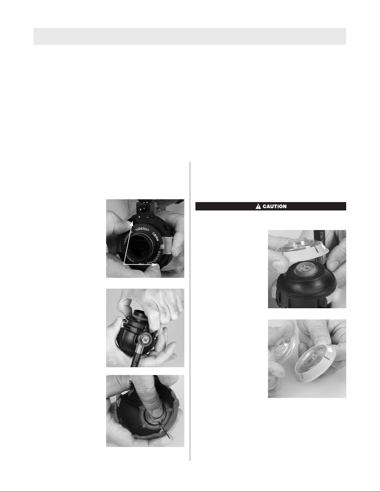
DISASSEMBLY
Removing the Regulator Cover and Spring
1. Remove the regulator cover.
a. Press and hold the
release buttons while
pressing the
regulator housing
retaining latches.
Latches
Adjustment of Valve Fork if Above the Maximum ..........8
Adjustment of Valve Fork if Below the Minimum ...........8
Reassembly.......................................................................9
Seal Ring.........................................................................9
Regulator Housing and Buttons .....................................9
Valve Assembly...............................................................9
Bypass Screen..............................................................10
Bypass Assembly .........................................................10
Diaphragm ....................................................................12
Regulator Cover............................................................12
Removing the Diaphragm
1. Remove the CBRN Shield.
Handle the CBRN shield by the rim only.
a. Lift the CBRN
shield assembly
and spring cap
off of the diaphragm
assembly.
b. Allow the cover to
drop into your palm.
c. Remove the spring
from the regulator
cover.
Note: Do not stretch the spring.
TAL 016 (L) Rev. 3 - 10096394
b. Lift the spring cap
off of the CBRN
shield assembly.
Spring
4
Page 5

FIREHAWK RESPONDER SECOND STAGE REGULATOR
2. Roll the edge of the
diaphragm off the lip of
the regulator housing.
3. Slide the diaphragm away from the bypass to
disengage it from the valve fork.
4. Secure the bypass knob in a vise.
Note: Use rubber pads or electrical tape on the vise to
protect the bypass knob.
a. Use a 7/16” socket
to unscrew the nut.
5. Remove the bypass
knob.
Disassembling the Bypass Assembly
1. Remove the regulator cover and spring. (See
Removing the Regulator Cover and Spring for
instructions.)
2. Remove the U-clip.
3. Unscrew the bypass
assembly and pull the
bypass assembly and
housing from the valve
housing.
6. Gently pull the bypass
assembly from the
bypass housing.
7. Turn the bypass
manifold upside down
and allow the bypass
stem to fall out.
5
TAL 016 (L) Rev. 3 - 10096394
Page 6

FIREHAWK RESPONDER SECOND STAGE REGULATOR
8. Use the o-ring removal
tool to remove the
o-ring. Be careful not
to scratch the bypass
stem. Discard the
o-ring.
9. Use the o-ring removal
tool to remove the
bypass insert assembly
o-rings. Be careful not
to scratch the o-ring
grooves. Discard the
o-rings.
Removing the Bypass Screen
3. Remove the old screen
and discard.
Note: Do not puncture the screen. The o-ring removal tool
can be used to rotate the screen counterclockwise until
it’s loose.
Removing the Valve Assembly
1. Remove the regulator cover, spring, and spring
retainer. (See Removing the Regulator Cover and
Spring for instructions.)
2. Remove the diaphragm. (See Removing the
Diaphragm for instructions.)
3. Remove the bypass insert. (See Disassembling the
Bypass Assembly for instructions.)
1. Use two 3/4”
wrenches to hold the
hose union and
unscrew the nipple.
2. Use the o-ring removal
tool to remove the
o-ring.
Note: Be careful not to scratch the o-ring groove. Discard
the o-ring.
4. Lift the valve assembly
out of the regulator
housing.
Disassembling the Regulator Housing Buttons
1. Use the o-ring removal tool to remove the old o-rings.
a. Be careful not to
scratch the o-ring
grooves. Discard the
o-rings.
TAL 016 (L) Rev. 3 - 10096394
6
Page 7

FIREHAWK RESPONDER SECOND STAGE REGULATOR
Valve Assembly
Height Gauge
P/N 10090457
INSPECTION OF THE VALVE FORK FOR PROPER
HEIGHT
b. Pull firmly on the
buttons to remove
them. Be careful not
to lose the springs.
c. Remove the old
o-rings. Be careful
not to scratch the oring grooves. Discard
the o-rings.
Removing the Seal Ring
Inspect and adjust valve fork height with the valve fork
pointing toward you. The valve fork assembly must move
up and down freely.
Adjustment Wheel
Fork
1. Press the top of the
valve fork to check
movement.
Valve Housing
Valve Locking Tab
Valve
Support
2. Use the Height Gauge to verify the fork height setting.
1. Use the o-ring removal
tool to remove the seal
ring.
a. Discard the seal ring.
Note: See Firehawk Second Stage Regulator
Replacement and Overhaul Kits for ordering
information.
3. Center the gauge in the valve fork.
Note: Ensure that the valve assembly is vertical and can
move freely.
Acceptable
range
7
TAL 016 (L) Rev. 3 - 10096394
Page 8

FIREHAWK RESPONDER SECOND STAGE REGULATOR
Ribs
Locking
Tab
Ribs
Locking
Tab
4. The top of the valve fork must be within the
acceptable range.
Acceptable Valve Fork Heights
Nominal height – Top of
fork level with center of
acceptable range.
Maximum Height – Top of
fork level with top of
acceptable range.
Above maximum height –
Top of fork above top of
acceptable range.
1. Slide the adjustment wheel and valve housing slightly
away from the valve support to allow the adjustment
wheel to rotate.
Note: The adjustment wheel cannot turn unless the ribs
are free from the locking tab.
Minimum Height – Top of
fork level with bottom of
acceptable range.
Note: If the top of the valve fork is above or below the
acceptable range, adjust the valve. Normally the valve
fork will not require adjustment. Do not adjust the valve if
the fork is within the acceptable range.
Adjusting Valve Fork Height for Proper Performance
Adjustment of Valve Fork if Above the Maximum
Inspect and adjust valve fork height with the valve fork
pointing toward you. Turn the Adjustment Wheel
clockwise to lower the fork. Turn the Adjustment Wheel
counterclockwise to raise the fork.
2. Turn the adjustment wheel clockwise to lower the fork.
3. Slide the adjustment wheel and valve housing back
into place.
4. Ensure that the valve lever and fork do not bind. The
fork should move up and down easily.
Adjustment for Valve Fork if Below the Minimum
Below minimum height –
Top of fork is below
acceptable range.
1. Slide the adjustment wheel and valve housing slightly
away from the valve support to allow the adjustment
wheel to rotate.
Note: The adjustment wheel cannot turn unless the ribs
are free from the locking tab.
TAL 016 (L) Rev. 3 - 10096394
8
Page 9

FIREHAWK RESPONDER SECOND STAGE REGULATOR
Ribs
Locking
Tab
Ribs
Locking
Tab
2. Turn the adjustment wheel counterclockwise to raise
the fork.
3. Slide the valve housing back into place. Ensure that
the locking tab engages the adjusting wheel.
4. Ensure that the valve lever and fork do not bind. The
fork should move up and down easily.
REASSEMBLY
Note: Flow test the regulator on the PosiChek3after
reassembly.
Note: Install the thinner
o-ring (P/N 10023509) to
the base of the post.
2. Install the springs and
insert the buttons.
Installing the Seal Ring
Seal Ring P/N 10031192
1. Apply a thin film of Christo-Lube (P/N 604070) to the
new seal.
2. Install the new seal ring
(P/N 10031192) onto
the regulator outlet and
seat it into the seal
groove.
Note: An unseated seal ring can cause an air leak.
Installing the Regulator Housing Buttons
O-Ring P/N 10023509
O-Ring P/N 10037951
1. Install new o-rings on the button posts.
a. Protect the o-rings by covering the post with tape
or thin pieces of paper.
b. Apply a thin film of Christo-Lube (P/N 604070) to
the new o-rings.
c. Install the o-rings.
3. Push firmly on the
buttons and install the
inner o-rings
(P/N 10037951).
Note: Install the thicker
o-ring (P/N 10037951) inside the housing.
Installing the Valve Assembly
Valve Assembly P/N 10087295
Note: Replacement of P/N 10030664-Valve Assembly,
requires P/N 10087301-Housing Assembly, and P/N
10092041-Diaphragm Spring.
1. Insert the valve into the
regulator housing with
the valve fork up and
facing away from the
bypass port.
9
TAL 016 (L) Rev. 3 - 10096394
Page 10

FIREHAWK RESPONDER SECOND STAGE REGULATOR
2. Push the valve into the regulator housing.
Installing the Bypass Screen
Bypass Screen P/N 10082485
O-Ring P/N 632736
1. Insert a new screen
(P/N 10082485).
a. Ensure that the
screen seats all
around the periphery.
5. Remove the protective tape or paper.
6. Carefully screw the
nipple into the hose
union.
7. Use a 3/4” wrench to
hold the hose union
and a 3/4” crowfoot
and inch pound torque
wrench to tighten the
nipple to 75 ± 5 in lbs.
2. Protect the o-ring from
the thread with tape or
thin pieces of paper.
3. Apply a small amount of Christo-Lube (P/N 604070) to
a new o-ring (P/N 632736)
4. Install the o-ring.
Assembling the Bypass Assembly
Bypass Stem P/N 10082482
O-Ring P/N 10082488
1. Install the bypass stem.
a. Apply a small amount of Christo-Lube (P/N 604070)
to the o-ring.
b. Install the o-ring
(P/N 10082488) on
the bypass stem
(P/N 10082482).
c. Insert the bypass stem.
TAL 016 (L) Rev. 3 - 10096394
10
Page 11

FIREHAWK RESPONDER SECOND STAGE REGULATOR
U-Clip
openings
2. Install the bypass insert.
a. Install a new o-ring (P/N 697453).
b. Protect the o-ring
by covering the
thread with tape
or thin pieces of
paper.
c. Slide the silicone
o-ring over the
protective paper or
tape.
3. Carefully install the
bypass assembly.
Note: To prevent damage
to the o-ring, use extra
caution when installing the
bypass assembly. Check
for evidence of o-ring
damage before proceeding.
O-ring damage may be
visible through u-clip
openings. Replace
damaged o-rings.
Note: Use several pieces of tape or paper to protect the
o-rings from all threads and edges.
c. Apply a small amount of Christo-Lube (P/N 604070)
to the o-rings.
d. Install the o-rings (P/N 10082487).
Note: Remove all
protective tape or paper
prior to assembly.
a. Apply a small amount of Loctite 271 to the thread of
the bypass insert assembly.
b. Secure the bypass knob in a vise.
Note: Use rubber pads or electrical tape on the vise
to protect the bypass knob.
c. Use an inch-pound
torque wrench, and
7/16” socket to
tighten the nut to 30
± 5 in lbs.
d. Screw the bypass
assembly into the
valve assembly.
11
TAL 016 (L) Rev. 3 - 10096394
Page 12

FIREHAWK RESPONDER SECOND STAGE REGULATOR
Note: Replace the Spring Cap (P/N 10047528) and
Tetraplex CBRN Shield (P/N 10044026) per overhaul
frequency. (See FireHawk® M7 Air Mask Maintenance
and Repair, Introduction (P/N 10093079) for required
overhaul frequency.)
e. Reinstall the u-clip.
Installing the Diaphragm
Diaphragm P/N 10039172
Spring Cap P/N 10047528
CBRN Shield P/N 10044026
1. Apply a thin coat of Christo-Lube (P/N 604070) to the
top rim of the regulator housing.
2. Slide the diaphragm
knob into the valve
fork slot.
Note: While installing the shield, the valve fork must be in
the UP position. Squeeze the buttons to ensure that the
fork is in the up position.
5. Apply a thin coating of Christo-Lube (P/N 604070) to
the bottom of the shield assembly.
6. Place the CBRN shield
over the diaphragm
assembly. Install the
spring cap over the
CBRN shield and lightly
tap to remove the
trapped air.
Installing the Regulator Cover
Regulator Cover P/N 10047664
Diaphragm Spring P/N 10092041
3. Slide the diaphragm
toward the bypass to
engage the fork.
a. Ensure that the tab
is engaged to the
fork by gently lifting
the diaphragm.
4. Roll the diaphragm
over the regulator
housing rim.
1. Install the spring into
the cover. Ensure that
the last coil is captured
by the regulator cover
tabs.
Double-check proper engagement by gently pulling on
the spring. Visually inspect the spring and tabs to
make sure that both tabs engage the spring. Ensure
that the spring is securely attached to the regulator
cover. Do not stretch the spring. Failure to follow this
warning may result in serious personal injury or death.
TAL 016 (L) Rev. 3 - 10096394
12
Page 13

FIREHAWK RESPONDER SECOND STAGE REGULATOR
2. Push regulator cover
and spring onto
regulator housing
until it locks.
Double-check proper engagement by pulling on the
regulator cover. Ensure that the regulator cover is
securely attached to the regulator housing. Failure to
follow this warning may result in serious personal
injury or death.
13
TAL 016 (L) Rev. 3 - 10096394
 Loading...