

Page 1

EVOLUTION®5200 and
EVOLUTION
®
5200HD
2
Thermal Imaging System
THIS MANUAL MUST BE READ
CAREFULLY BY ALL INDIVIDUALS
WHO HAVE OR WILL HAVE THE
RESPONSIBILITY FOR USING OR
SERVICING THE PRODUCT. Like
any piece of complex equipment,
the unit will perform as designed
only if it is used and maintained in
accordance with the manufacturer’s instructions. OTHERWISE IT
COULD FAIL TO PERFORM AS
DESIGNED AND RESULT IN
SEVERE PERSONAL INJURY OR
DEATH.
The warranties made by Mine Safety
Appliances Company with respect to
the product are voided if the product is
not used and serviced in accordance
with the instructions in this manual.
Please protect yourself and others by
following them. We encourage our customers to write or call regarding this
equipment prior to use or for any additional information relative to use or
repairs. During regular working hours,
cal l 1-877-MSA-FIRE.
By order of the US Department of
Commerce, in conjunction with the US
Department of State and DOD, this
Thermal Imaging Camera may not be
resold, re-exported, transferred, or otherwise disposed of outside of the country named as the location of foreign end
use, either in its original form or after
being incorporated into other end
items, without the prior written
approval of the US Department of
Commerce. Violation of this regulation
may result in fine and/or imprisonment.
© MINE SAFETY APPLIANCES COMPANY 2009 All Rights Reserved
This manual is available on the internet at
www.msanet.com
Manufactured by
MSA NORTH AMERICA
P.O. Box 427, Pittsburgh, Pennsylvania 15230
(L) Rev 1 10075165
OPERATION AND INSTRUCTIONS
"
WARNING
Page 2

i
Table of Contents
BEFORE USE/DESCRIPTION . . . . . . . . . . . . . . . . . . . . . . . . . . . . . . . . .1
Figure 1. The Evolution 5200 TICand Evolution 5200HD2 TIC . . . . . . . . . . . . . . . .1
INTRODUCTION . . . . . . . . . . . . . . . . . . . . . . . . . . . . . . . . . . . . . . . . . . . . . . . . . . . . . .1
FEATURES AND BENEFITS . . . . . . . . . . . . . . . . . . . . . . . . . . . . . . . . . . . . . . . . . . . . .1
DESCRIPTION . . . . . . . . . . . . . . . . . . . . . . . . . . . . . . . . . . . . . . . . . . . . . . . . . . . . . . . .1
ABOUT THE CAMERA . . . . . . . . . . . . . . . . . . . . . . . . . . . . . . . . . . . . . . . . . . . . . . . . .1
Figure 2. . . . . . . . . . . . . . . . . . . . . . . . . . . . . . . . . . . . . . . . . . . . . . . . . . . . . . . . . . .2
Specifications . . . . . . . . . . . . . . . . . . . . . . . . . . . . . . . . . . . . . . . . . . . . . . . . . . . . .2
WARNINGS AND CAUTIONS . . . . . . . . . . . . . . . . . . . . . . . . . . . . . . . . . .3
" WARNING . . . . . . . . . . . . . . . . . . . . . . . . . . . . . . . . . . . . . . . . . . . . . . . . . . . . . .3
" CAUTION . . . . . . . . . . . . . . . . . . . . . . . . . . . . . . . . . . . . . . . . . . . . . . . . . . . . . .3
LIMITATIONS . . . . . . . . . . . . . . . . . . . . . . . . . . . . . . . . . . . . . . . . . . . . . . . . . . . . . .3
OPERATION . . . . . . . . . . . . . . . . . . . . . . . . . . . . . . . . . . . . . . . . . . . . . . .4
OPERATION . . . . . . . . . . . . . . . . . . . . . . . . . . . . . . . . . . . . . . . . . . . . . . . . . . . . . . . . . .4
Getting Started . . . . . . . . . . . . . . . . . . . . . . . . . . . . . . . . . . . . . . . . . . . . . . . . . . . . . . .4
TURNING THE CAMERA ON AND OFF . . . . . . . . . . . . . . . . . . . . . . . . . . . . . . . . . . . .4
Normal Mode . . . . . . . . . . . . . . . . . . . . . . . . . . . . . . . . . . . . . . . . . . . . . . . . . . . . . . . .4
Figure 3. ON/OFF Button . . . . . . . . . . . . . . . . . . . . . . . . . . . . . . . . . . . . . . . . . . . . .4
Standby Mode . . . . . . . . . . . . . . . . . . . . . . . . . . . . . . . . . . . . . . . . . . . . . . . . . . . . . . . .4
Turning the Camera OFF . . . . . . . . . . . . . . . . . . . . . . . . . . . . . . . . . . . . . . . . . . . . . . .4
USER INTERFACE- INDICATORS AND WARNINGS . . . . . . . . . . . . . . . . . . . . . . . . . .4
2X Digital Zoom (Optional Feature on the Evolution 5200HD2TIC) . . . . . . . . . . . . . .4
Figure 4. Evolution 5200 and Evolution 5200HD2 TIC User Interface . . . . . . . . . . .5
On-Screen Indicators . . . . . . . . . . . . . . . . . . . . . . . . . . . . . . . . . . . . . . . . . . . . . . . . . .5
LED Indicators . . . . . . . . . . . . . . . . . . . . . . . . . . . . . . . . . . . . . . . . . . . . . . . . . . . . . . .5
On-Screen Indicators . . . . . . . . . . . . . . . . . . . . . . . . . . . . . . . . . . . . . . . . . . . . . . . . . .5
LED Indicators . . . . . . . . . . . . . . . . . . . . . . . . . . . . . . . . . . . . . . . . . . . . . . . . . . . . . . .5
" WARNING . . . . . . . . . . . . . . . . . . . . . . . . . . . . . . . . . . . . . . . . . . . . . . . . . . . . . .6
Additional Indicators . . . . . . . . . . . . . . . . . . . . . . . . . . . . . . . . . . . . . . . . . . . . . . . . . . .6
Direct Video Connection . . . . . . . . . . . . . . . . . . . . . . . . . . . . . . . . . . . . . . . . . . . . . . . .6
Figure 5. TIC with SMA to BNC Connector . . . . . . . . . . . . . . . . . . . . . . . . . . . . . . .6
BATTERY CARE AND INSTALLATION . . . . . . . . . . . . . . . . . . . . . . . . .7
RECHARGEABLE BATTERIES . . . . . . . . . . . . . . . . . . . . . . . . . . . . . . . . . . . . . . . . . . .7
BATTERY INSTALLATION AND CARE . . . . . . . . . . . . . . . . . . . . . . . . . . . . . . . . . . . .7
BATTERY MAINTENANCE . . . . . . . . . . . . . . . . . . . . . . . . . . . . . . . . . . . . . . . . . . . . . . .7
STAND-ALONE BATTERY CHARGER . . . . . . . . . . . . . . . . . . . . . . . . . . . . . . . . . . . . . .7
" WARNING . . . . . . . . . . . . . . . . . . . . . . . . . . . . . . . . . . . . . . . . . . . . . . . . . . . . . .7
OPERATION . . . . . . . . . . . . . . . . . . . . . . . . . . . . . . . . . . . . . . . . . . . . . . . . . . . . . . . . .7
CHARGING THE BATTERY . . . . . . . . . . . . . . . . . . . . . . . . . . . . . . . . . . . . . . . . . . . . . .7
Figure 6. . . . . . . . . . . . . . . . . . . . . . . . . . . . . . . . . . . . . . . . . . . . . . . . . . . . . . . . . . .7
Page 3

ii
TIC ACCESSORIES . . . . . . . . . . . . . . . . . . . . . . . . . . . . . . . . . . . . . . . . .9
TIC Configurations and Accessories . . . . . . . . . . . . . . . . . . . . . . . . . . . . . . . . . . . . . . . .9
Evolution 5200 and Evolution 5200HD2TIC Standard Components . . . . . . . . . . . . . .9
Other Options . . . . . . . . . . . . . . . . . . . . . . . . . . . . . . . . . . . . . . . . . . . . . . . . . . . . . . . .9
Carrying Attachments . . . . . . . . . . . . . . . . . . . . . . . . . . . . . . . . . . . . . . . . . . . . . . . . . .9
Display Sun Shroud . . . . . . . . . . . . . . . . . . . . . . . . . . . . . . . . . . . . . . . . . . . . . . . . . . .9
Disposable Display Covers . . . . . . . . . . . . . . . . . . . . . . . . . . . . . . . . . . . . . . . . . . . . . .9
Custom Carrying Case . . . . . . . . . . . . . . . . . . . . . . . . . . . . . . . . . . . . . . . . . . . . . . . . .9
Mounting Bracket (FIGURE 7) . . . . . . . . . . . . . . . . . . . . . . . . . . . . . . . . . . . . . . . . . . .9
Tripod Mounting Adapter . . . . . . . . . . . . . . . . . . . . . . . . . . . . . . . . . . . . . . . . . . . . . . .9
Tripod . . . . . . . . . . . . . . . . . . . . . . . . . . . . . . . . . . . . . . . . . . . . . . . . . . . . . . . . . . . . . .9
Reflective ID Label . . . . . . . . . . . . . . . . . . . . . . . . . . . . . . . . . . . . . . . . . . . . . . . . . . . .9
Figure 7. Mounting Bracket . . . . . . . . . . . . . . . . . . . . . . . . . . . . . . . . . . . . . . . . . . .9
EVOLUTION 5000 SERIES UNIVERSAL
TRUCK-MOUNTED CHARGING SYSTEM OPERATION . . . . . . . . . . .10
Power Status LED Indicators . . . . . . . . . . . . . . . . . . . . . . . . . . . . . . . . . . . . . . . .10
Battery LED Indicators . . . . . . . . . . . . . . . . . . . . . . . . . . . . . . . . . . . . . . . . . . . . .10
Figure 8. Universal Charger/Camera Engagement Sequence . . . . . . . . . . . . . . . .10
Figure 9. . . . . . . . . . . . . . . . . . . . . . . . . . . . . . . . . . . . . . . . . . . . . . . . . . . . . . . . . .11
Figure 10. . . . . . . . . . . . . . . . . . . . . . . . . . . . . . . . . . . . . . . . . . . . . . . . . . . . . . . . .11
Figure 11. . . . . . . . . . . . . . . . . . . . . . . . . . . . . . . . . . . . . . . . . . . . . . . . . . . . . . . . .11
EVOLUTION 5000 SERIES UNIVERSAL
TRUCK-MOUNTED CHARGING SYSTEM INSTALLATION . . . . . . . . .12
Operation . . . . . . . . . . . . . . . . . . . . . . . . . . . . . . . . . . . . . . . . . . . . . . . . . . . . . . . . . . . .12
Getting Started . . . . . . . . . . . . . . . . . . . . . . . . . . . . . . . . . . . . . . . . . . . . . . . . . . . . . .12
" WARNING . . . . . . . . . . . . . . . . . . . . . . . . . . . . . . . . . . . . . . . . . . . . . . . . . . . . .12
What you will need: . . . . . . . . . . . . . . . . . . . . . . . . . . . . . . . . . . . . . . . . . . . . . . . . . .12
Installation Guidelines . . . . . . . . . . . . . . . . . . . . . . . . . . . . . . . . . . . . . . . . . . . . . . . . .12
Mounting Hanging Channels . . . . . . . . . . . . . . . . . . . . . . . . . . . . . . . . . . . . . . . . . . .12
Mounting the Universal Truck-Mounted Charger to Channels . . . . . . . . . . . . . . . . . .12
Electrical Connections . . . . . . . . . . . . . . . . . . . . . . . . . . . . . . . . . . . . . . . . . . . . . . . .13
Power Requirements . . . . . . . . . . . . . . . . . . . . . . . . . . . . . . . . . . . . . . . . . . . . . . . . .13
Electrical Specifications . . . . . . . . . . . . . . . . . . . . . . . . . . . . . . . . . . . . . . . . . . . .13
Installation . . . . . . . . . . . . . . . . . . . . . . . . . . . . . . . . . . . . . . . . . . . . . . . . . . . . . . . . .13
THERMAL IMAGING CAMERA WARRANTY . . . . . . . . . . . . . . . . . . . .14
EVOLUTION THERMAL IMAGING CAMERA
EXTENDED SERVICE APPLICATION . . . . . . . . . . . . . . . . . . . . . . . . . .15
Page 4

iii
MAINTENANCE AND ADJUSTMENTS . . . . . . . . . . . . . . . . . . . . . . . . .16
GENERAL MAINTENANCE . . . . . . . . . . . . . . . . . . . . . . . . . . . . . . . . . . . . . . . . . . . . .16
Cleaning . . . . . . . . . . . . . . . . . . . . . . . . . . . . . . . . . . . . . . . . . . . . . . . . . . . . . . . . . . .16
" WARNING . . . . . . . . . . . . . . . . . . . . . . . . . . . . . . . . . . . . . . . . . . . . . . . . . . . . .16
TROUBLESHOOTING THE TRUCK-MOUNTED CHARGING SYSTEM . . . . . . . . . . .16
Troubleshooting Guidelines . . . . . . . . . . . . . . . . . . . . . . . . . . . . . . . . . . . . . . . .16
" WARNING . . . . . . . . . . . . . . . . . . . . . . . . . . . . . . . . . . . . . . . . . . . . . . . . . . . . .16
" CAUTION . . . . . . . . . . . . . . . . . . . . . . . . . . . . . . . . . . . . . . . . . . . . . . . . . . . . .16
SERVICE . . . . . . . . . . . . . . . . . . . . . . . . . . . . . . . . . . . . . . . . . . . . . . . . . . . . . . . . . . . .17
Field Repairs and Maintenance . . . . . . . . . . . . . . . . . . . . . . . . . . . . . . . . . . . . . . . . .17
Internal PCB Fuse Replacement . . . . . . . . . . . . . . . . . . . . . . . . . . . . . . . . . . . . . . . .17
Figure 12. Location of Power Cable, Phoenix Connector, and Internal Fuse . . . .17
MSA FACTORY REPAIR & SERVICE POLICY CARD . . . . . . . . . . . . . . . . . . . . . . . . .18
EVOLUTION 5000 SERIES TIC SPARE PARTS LIST . . . . . . . . . . . . . .19
Page 5

1
INTRODUCTION
Congratulations on the purchase of your new MSA
Evolution 5200 Thermal Imaging System! This
hand-held unit provides advanced thermal imaging
technology backed by years of MSA quality,
dedication, and service.
The Evolution 5200 Series Thermal Imaging
Camera (TIC) is designed to assist firefighters to
see in low visibility conditions of smoke and
darkness. This high definition thermal imaging
camera provides the latest in available thermal
imaging technology for the fire service.
FEATURES AND BENEFITS
The Evolution 5200 Series Thermal Imaging
Camera (TIC) can be used to aid firefighting in
scenarios such as:
• Search and rescue missions
• Initial size-up/Scene assessment
• Locating the seat of the fire
• Locating fire extension
• Identifying potential flashover situations
• Determining entry and ventilation points
• Hazmat situations
• Response vehicle navigation (darkness or
heavy smoke)
• Preplanning/Fire code inspections
• Overhaul
• Assistance for law enforcement
DESCRIPTION
The Evolution 5200 and Evolution 5200HD2TICs
are highly sophisticated pieces of electronic
equipment. The unit was designed to withstand the
firefighting conditions of heat, driving spray, and
frequent impact normally seen by a firefighter.
Extension beyond these demands may damage
the camera and render it inoperable. It is not
recommended that the camera run for extended
periods in high-heat conditions.
The Evolution 5200 Series TICs are intended as
an aid to fire and rescue operations in conditions
of poor visibility created by smoke and darkness,
and are not a replacement for standard firefighting
techniques and precautions. Users must ensure
that the fire department's standard operating
procedures are followed while using the cameras.
ABOUT THE CAMERA
The Evolution 5200 Series TICs are as follows:
• equipped with a state-of-the-art 160 x 120
(Evolution 5200) or a state-of-the-art
320 x 240 (Evolution 5200HD2)
microbolometer thermal detector to provide
the clearest high-definition images available
in fire and non-fire environments
• the Evolution 5200HD2features a 2X digital
zoom feature, providing the user with
magnified image information
• equipped with a large screen, high definition
display to allow for multiple firefighters to view
the action
• ergonomically designed for the firefighting
environment
• available with desk top and truck mounted
charging options
• designed with the most ergonomically correct
balance, with the center of gravity located in
the users hand
• dust and water-resistant to withstand shortterm immersion in up to three feet of water in
accordance with IP67 specifications
• available with multiple carrying and
attachment options to suit user preferences the Evolution 5200 TIC is a tool
Figure 1. The Evolution 5200 TIC
and Evolution 5200HD
2
TIC
BEFORE USE/DESCRIPTION
Page 6

• the Evolution 5200 TIC detects thermal
energy radiated/generated from surrounding
objects and converts this energy into a visual
image.
• Hot objects appear white.
• Cold objects appear black.
Specifications
CONSTRUCTION Flame retardant
(material passes
simulated NFPA
direct flame exposure
test). IP67 [withstands
immersion to 3 feet
(1meter)]
APPROXIMATE HEIGHT 10.8 inches (275 mm)
DIMENSIONS
WIDTH 8.1 inches (205 mm)
LENGTH 4.4 inches (112 mm)
SENSOR Uncooled VOX
microbolometer
ARRAY SIZE EVOLUTION 160 X 120
5200
EVOLUTION 320 X 240
5200HD
2
WEIGHT 2.8 lbs.
POWER Rechargeable
SOURCE LiIon batteries
POWER USAGE AT 72°F (22°C) Less than 6.0 W
nominal
OPERATING 1 Li Ion PACK 2 hours at nominal
TIME 72°F (22°C)
FIELD OF VIEW EVOLUTION 55° H; 44° V
5200
EVOLUTION 36° H; 27° V
5200HD
2
NET HIGH
EQUIVALENT SENSITIVITY .065°C, 65 mK
TEMPERATURE
DIFFERENCE LOW
SENSITIVITY .240°C, 240 mK
VIDEO OUTPUT RS-170
This device complies with part 15 of the FCC
Rules. Operation is subject to the following
two conditions: (1) This device may not cause
harmful interference, and (2) this device must
accept any interference received, including
interference that may cause undesired
operation.
Figure 2.
2
Page 7

1. The user must be trained and thoroughly
familiar with the proper operation and
limitations of the thermal imaging system
prior to use. Use in controlled live-burn
exercises is suggested before using the
equipment in actual emergency situations.
Improper use of the equipment in a hazardous
atmosphere could result in
serious personal injury or death.
2. Do not rely on the thermal imaging system as
the sole means of navigation or deviate from
standard fire-fighting navigational practices
during use. Although the system provides an
image in dark and smoky environments, the
user may become disoriented or lost in such
environments if the system becomes
inoperative.
Most electronic devices will cease to operate
at certain high temperature extremes. Tests
on the Evolution 5200 and Evolution 5200HD
2
TIC indicate that they will provide an
acceptable image when subjected to an
ambient temperature of approximately 120°C
(248°F) for 20 minutes. Exposure to
conditions exceeding these will result in
deterioration and loss of image.
3. Thermal energy is not transmitted through
glass or underwater and may be reflected off
of smooth surfaces. Disorientation may occur
if the user is unaware of these properties.
4. This thermal imaging system is not rated as
"Intrinsically Safe." Do not use the system in
environments or atmospheres where static or
sparks may cause an explosion.
5. Before entering a hostile environment, test
the thermal imaging system as specified in
the instructions to ensure that it is functional.
After each use, inspect the system to
determine if servicing is required.
6. Exposure to high temperature environments
for an extended period of time may cause
degradation or loss of thermal image. Avoid
heat saturation or over exposure of the
equipment. If degradation of the thermal
image is observed, immediately remove the
equipment from the high heat environment
and allow it to cool until the thermal image
returns to normal; otherwise, the system may
become inoperative.
7. Replacement batteries must exactly match the
ratings and configuration of those supplied
with the equipment. Use of unapproved
batteries may render the system inoperative.
8. Do not remove the thermal imaging camera
cover or casing as the system operates on
high voltage. Only authorized personnel may
service the unit.
FAILURE TO FOLLOW THE ABOVE WARNINGS
CAN RESULT IN SERIOUS PERSONAL INJURY
OR DEATH.
1. Ensure battery is fully charged before use. If
not fully charged, the system will not operate
for the specified amount of time. Monitor
battery level during use and immediately exit
the hazardous area when a low battery
warning is observed.
2. Electromagnetic radiation (radio transmissions)
may cause interference. Minimize nearby radio
transmissions if excessive interference occurs.
3. To avoid lens fogging, the user may coat the
lenses and view finder with MSA anti-fog
material (MSA P/N 13016).
4. Do not point the thermal imaging camera
directly at the sun; otherwise, damage to the
detector may occur.
5. Do not drop the thermal imaging camera.
Although the camera is designed to withstand
normal impacts that occur in fire service, such
impacts may alter the focus or damage the
unit.
FAILURE TO FOLLOW THE ABOVE CAUTIONS
CAN RESULT IN PERSONAL INJURY OR
EQUIPMENT DAMAGE.
1. Although the Evolution 5200 and Evolution
5200HD
2
TICs are IP67 waterproof, these
systems do not provide underwater thermal
images.
2. The Evolution 5200 and Evolution 5200HD
2
TICs do not provide images through glass,
water, or shiny objects; these surfaces act like
mirrors to the system.
3. The Evolution 5200 and Evolution 5200HD
2
TICs do not improve impaired vision. Users
with impaired vision should continue to use
ophthalmic devices while using the systems.
LIMITATIONS
"
CAUTION
"
WARNING
3
WARNINGS AND CAUTIONS
Page 8

4
OPERATION
Getting Started
The rechargeable batteries supplied with the
Evolution 5200 and Evolution 5200HD2TICs must
be fully charged before use. Also, periodically
check and replace the battery in an actively-used
imager.
• See "Battery Care and Installation" later in
this manual.
TURNING THE CAMERA ON AND OFF
Normal Mode
1. To turn the camera ON, press the POWER
(green) button on the TIC handle (see
FIGURE 3) and hold for approximately one
second.
2. Wait approximately five seconds for the
infrared sensor electronics to self-test.
• The green POWER LED (located near
the display) lights.
• After several seconds, the thermal image
appears on the screen.
3. Verify the camera is functioning by aiming at
an object or person until the thermal image
appears in the camera viewer.
• The thermal imaging camera is now
ready for use.
NOTE: The Evolution 5200 or Evolution
5200HD2 POWER button has a
momentary pushbutton switch that
requires deliberate, one-second
activation to activate. Rapid repeated
depression of the POWER button
may cause the TIC start-up software
to lock, and a picture will not display
(LEDs may still activate). If this
condition occurs, simply turn the TIC
OFF and back ON using slow,
deliberate button presses.
Standby Mode
To conserve battery consumption, the camera is
equipped with a Standby Mode feature.
4. To activate, press the POWER button until:
• The display shuts OFF.
• The system STATUS LED begins
to flash green.
5. To return to Normal Mode from Standby
Mode, press the POWER (green) button until:
• The display immediately reactivates
without warm-up time.
• The system STATUS LED turns
to solid green.
Turning the Camera OFF
6. To turn the camera OFF, press and hold the
green POWER button for four seconds.
• As a safety feature to avoid inadvertent
power-OFFs, the green POWER button must
be held for four seconds to turn OFF the
camera.
• The green STATUS LED flashes during the
power-off countdown to confirm effective
button press.
• When all LED indicators shut OFF, the user
may release the green POWER button.
• The camera is now OFF.
USER INTERFACEINDICATORS AND WARNINGS
2X Digital Zoom (Optional Feature on the
Evolution 5200HD2TIC)
To activate, press the POWER button until:
• The 2X indicator appears on the camera's
display (above the green system status LED).
To return to Normal Mode from 2X Digital Zoom
Figure 3. ON/OFF Button
OPERATION
Page 9

Mode, press the POWER (green) button until:
• The display immediately returns to the
standard view and the 2X indicator is no
longer present.
NOTE: The 2X Digital feature replaces the
Standby-Mode feature on the
Evolution 5200HD2 TIC.
The Evolution 5200 and Evolution 5200HD2 TIC
come standard with five LED Indicators for System
Status, Battery Life and Overtemp status. When
the TIC is turned ON, all LEDs "flash" for two to
three seconds; then, the thermal picture appears.
When the TIC is turned OFF, all LEDs are
darkened. Also, the TIC has on-screen indicators
for low sensitivity, shutter and optional quick-temp
(FIGURE 4).
On-Screen Indicators
A Low sensitivity firefighting mode indicator
B Shutter indicator
C Optional Quick - Temp Indicator and Digital
Temperature Measurement
LED Indicators
D Over - Temperature Warning
E System Status Indicator
F Battery Status Indicators.
On-Screen Indicators
A - Low Sensitivity Mode Indicator -
An on-screen sensitivity indicator ("L") informs
the user when the camera is in the low
sensitivity mode.
• This mode occurs when the thermal imager
senses an environment above 160°C or
320°F.
• Dynamic Range is extended while in this
mode to provide greater image details of the
surroundings.
In high-heat conditions, the TIC will automatically
enter the Low Sensitivity mode. While in Low
Sensitivity mode, the TIC's dynamic range is
extended, thereby allowing the user to make better
distinction of objects and people within a higher
temperature range. When the Evolution 5200 TIC
is in Low Sensitivity mode, the letter "L" appears in
the lower left corner of the display.
B - Shutter Indicator -
An on-screen indicator that tells the user when the
TIC is shuttering appears as a green square in the
upper left corner of the display.
While the TIC is in operation, it is periodically
necessary for the TIC to refresh the focal plane in
order to operate properly. This occurs via an
internal shutter mechanism. When the TIC
shutters, the image on the display temporarily
freezes for about one second. Shuttering can
occur more frequently in higher heat conditions.
This is normal for all microbolometer - based TICs.
C - Optional Quick-Temp Indicator -
On-screen operating Quick Temp spotter and
vertical bar gauge spans temperatures from 0°F
(0°C) to 300°F (150°C) in High Sensitivity mode
and 0°F (0°C) to 1000°F (500°C) in Low Sensitivity
mode for objects located in the spotter. The digital
temperature feature displays the approximate
numeric value of the temperature of objects
located in the spotter.
G - Optional 2X Digital Zoom Indicator
on the Evolution 5200 TIC -
An on-screen indicator that tells the user when the
TIC display is in the Zoom mode, appears as
[ 2X ] in the lower center of the display.
LED Indicators
D - Over Temperature Warning -
Warning activates when the system electronics
approach maximum recommended operating
temperature limits.
• Not lit indicates system is within operational
thermal limits
• Flashing Red indicates the TIC has exceeded
recommended operational thermal limits.
Figure 4. Evolution 5200 and
Evolution 5200HD2 TIC User Interface
5
Page 10

Most electronic devices will cease to
operate at certain high temperature
extremes. Tests on the Evolution 5200
and
Evolution 5200HD
2
TICs indicate that they will provide an acceptable image when subjected to an
ambient temperature of approximately 120°C (248°F) for about ten minutes. Exposure to conditions exceeding these will result in deterioration
and loss of image.
E - System Status Indicator -
A single LED shows the operational status of
the TIC.
• Green indicates the TIC is ON and fully
operational
• Flashing Green indicates the TIC is ON and
in power-saving Standby mode.
F - Battery Status Indicator -
Battery capacity is shown by a row of three LEDs:
one green, one yellow, and one red. Only one of
the three battery status indicators will be
illuminated at any one time.
• Green indicates full or nearly full battery
capacity
• Yellow indicates marginal battery capacity
• Red indicates battery warning and nominally
15 minutes of battery life remaining
• Flashing Red indicates battery shutdown is
imminent (about one minute of warning time).
Additional Indicators
Optional Heat Seeker Plus Indicator -
The optional Heat Seeker Plus indicator adds
shades of color to objects in the scene reaching
high temperatures in both High and Low Sense
mode. The shades of color allow for some details
of the object to be seen for easier identification.
In High Sensitivity mode:
• The color of objects reaching 275°F (135°C)
will be yellow, starting with light shades
changing to darker shades, and then moving
to light and dark shades of orange as the
temperature increases.
• Once objects reach a temperature of297°F
(147°C), they become red starting with light
shades changing to darker shades up to a
temperature of 320°F (160°C).
In Low Sensitivity mode:
• The color of objects reaching 842°F (450°C)
will be yellow, starting with light shades
changing to darker shades, and then moving
to light and dark shades of orange as the
temperature increases.
• Once objects reach a temperature of 914°F
(490°C), they become red, starting with light
shades changing to darker shades up to a
temperature of 1040°F (560°C).
System Fault Indicator -
All five LEDs will flash if a system fault is detected.
The TIC's internal computer runs a self-diagnostic
program. If a problem with the internal component
is detected, a fault will be signaled and the LEDs
will flash.
Direct Video Connection
If you plan to use the TIC for viewing or recording
direct video, the Evolution 5200 and Evolution
5200HD2TICs are equipped with an SMA-type
video out connector located below the display,
next to the handle. Also included is an adapter
cable to a BNC connection (FIGURE 5).
If you plan to use the video out capability, attach
the SMA connector end and rout the adapter cable
to and through the front handle. The unit can then
be quickly attached to a video display using a BNC
connection.
"
WARNING
Figure 5. TIC with
SMA to BNC Connector
6
Page 11

RECHARGEABLE BATTERIES
The Evolution 5200 and Evolution 5200HD2TICs
run on one Lithium Ion battery; one battery is
required for TIC operation.
BATTERY
INSTALLATION AND CARE
1. Place the unit on a clean, non-abrasive
surface and lean the unit forward.
2. Unhook the battery latch and open the
battery compartment.
3. Place the battery inside the battery
compartment with the battery logo and arrow
facing right and pointing toward the top of
the TIC.
4. Close and latch the battery compartment.
BATTERY MAINTENANCE
After each use, inspect:
• battery contacts for damage
• batteries for damage or leakage
• to ensure battery charger is functioning
properly by:
• placing battery into the charger
• checking that the battery charger LEDs
react accordingly.
NOTE: Batteries not passing this inspection must
be removed from service until the proper
repairs are made.
STAND-ALONE
BATTERY CHARGER
This charging system is not rated as
"intrinsically safe." Do not use the
system in environments or atmospheres where static or spark may
cause an explosion.
Do not remove the outer housing of
the Charger. Only authorized personnel may service the unit.
The Charger must only be used for
charging Evolution rechargeable
Lithium Ion Battery Packs.
Do not use damaged chargers.
Do not attempt to charge damaged
packs.
Do not use the charger outdoors.
FAILURE TO FOLLOW THE ABOVE
WARNING CAN RESULT IN SERIOUS
PERSONAL INJURY OR DEATH.
OPERATION
Choose the proper adapter cord power source to
be used.
1. For standard AC operation: Plug the DC
plug of the AC/DC Adapter into the charger
and plug the AC Adapter into any standard
110-VAC outlet.
2. For DC Power Adapter operation: Plug the
DC Power Adapter Cord into the charger and
plug the other end into any DC 12-V power
source that offers a cigarette-lighter type
socket.
CHARGING THE BATTERY
1. Connect the unit with either AC/DC Power
Adapter or DC Car Power Adapter.
2. Place the battery into the unit.
• StandBy Mode:
• Without any battery installed, the
charger will flash the LED marked
MED, indicating that the charger is
standing by and waiting for a battery
to be connected.
• Phase 1 - Initial Charge:
• All three LEDs flash in sequence from
MED (left) to MAX (right)
• If the battery is low, this will be the
first charge phase
Figure 6.
"
WARNING
7
BATTERY CARE AND INSTALLATION
Page 12

8
• With high capacity batteries, this
phase can sometimes be the longest
of the three phases
• With some low capacity batteries and
batteries reaching the end of their life,
this phase can be very short.
NOTE: When a battery is first connected, the
LEDs may instantly indicate MED, HI
and MAX charge, depending on the
charge status of the battery. The
process will continue normally from
that point forward.
NOTE: It is normal for the charger, AC
adapter, or the battery to become
warm during charging.
• Phase 2 - MED Charge:
• MED LED is ON continuously and
other LEDs are flashing in sequence
• At this point, the battery is typically
about 50% charged.
• Phase 3 - HI Charge:
• The MED and HI LEDs are ON and
the MAX LED is flashing
• At this point, the battery is typically
about 70% charged.
• Phase 4 - MAX Charge:
• All three LEDs are ON at the
same time
• Charging is complete and the battery
is fully charged
• It is recommended to remove the
battery at this time.
3. Remove the battery from the unit.
• The battery is now ready for use.
NOTE: Error Condition - Charge Terminated -
If the If the battery is removed before a
complete charge is reached, the charger
continues indicating the last complete
charging phase for up to one minute. After
that time, an "Error" indication appears on
the LEDs (shown by the MED and MAX
LEDs coming ON together while the HI
LED is OFF).
The Error Condition is also indicated if
the charger senses any problem with the
battery being charged. To reset the Error
Condition, unplug the charger from the
power adapter for a few seconds; then,
reconnect the charger to the power
adapter. If the Error occurs again,
there may be a defect in the battery that
prevents safe charging.
Page 13
9
TIC Configurations and Accessories
The Evolution 5200 or the Evolution 5200HD2 TIC
can be purchased as a complete kit with
accessories or can be custom configured to your
requirements under the Assemble to Order (ATO)
System. There are several part numbered kits to
choose from. Please see the Evolution 5200 or
Evolution 5200HD
2
Brochure for complete
ordering information.
Evolution 5200 and Evolution 5200HD2TIC
Standard Components
All Evolution TICs come standard with the
following items:
• Thermal Imaging Camera
• One Rechargeable Lithium Ion Battery
• Caribiner Attachment
• Standard Universal Charger Kit with Cigarette
Lighter Adapter or Truck Mounted charger
• Care and Use Video
• SMA Video Out Connector
• Instruction Manual.
The Evolution 5200 and Evolution 5200HD
2
TIC
can be ordered as standard kit part numbers or as
Assemble to Order. See ordering information.
Other Options
Carrying Attachments
The Evolution 5200 and 5200HD
2
Thermal
Imaging Cameras (TICs) come standard with a
caribiner attachment. Additionally, users can
choose to purchase any one of three optional
carrying attachments:
Wrist Strap/Bunker Clip - Attaches to the TIC
and includes a clip for securing the TIC to bunker
gear while not in use.
Shoulder strap - Attaches to the TIC to allow for
easy carriage of the camera while not in use.
Retractable Lanyard - Attaches to the TIC to
allow for easy carriage and quick use of the
camera while attached to the user's belt or gear.
Lanyard easily retracts the camera back into place
when not in use.
Display Sun Shroud
Display Shroud allows for crisp/clear viewing of
the LCD screen while in bright sunlight.
NOTE: It is NOT recommended that reflective trim
pieces be placed on the main camera
housing if the TIC is used with a truckmounted charger, as it may interfere with
making adequate contact.
Disposable Display Covers
A package of three Disposable Display Covers
provides replaceable protection of the 3.5" LCD.
Custom Carrying Case
The Durable Carrying Case allows for storage and
transport of the TIC, batteries, charger, and
carrying attachments.
Mounting Bracket (FIGURE 7)
The Non-Charging Mounting Bracket enables
convenient storage of the Evolution 5200 TIC.
Tripod Mounting Adapter
The Tripod Mounting Adapter allows for mounting
of the TIC onto any standard tripod.
Tripod
The Tripod allows for stationary viewing of the
thermal imaging camera. The Tripod must be used
with the Tripod Adapter.
Reflective ID Label
The Reflective ID Label Kit includes one sheet of
colored accent labels designed to personalize the
TIC. Labels fit on the top and sides of the TIC and
may be written on to further assist in TIC
identification.
Figure 7. Mounting Bracket
TIC ACCESSORIES
Page 14

10
To charge the TIC and spare batteries using the
Evolution 5000 Series Truck-Mounted Charging
System make sure the TIC charging pins and
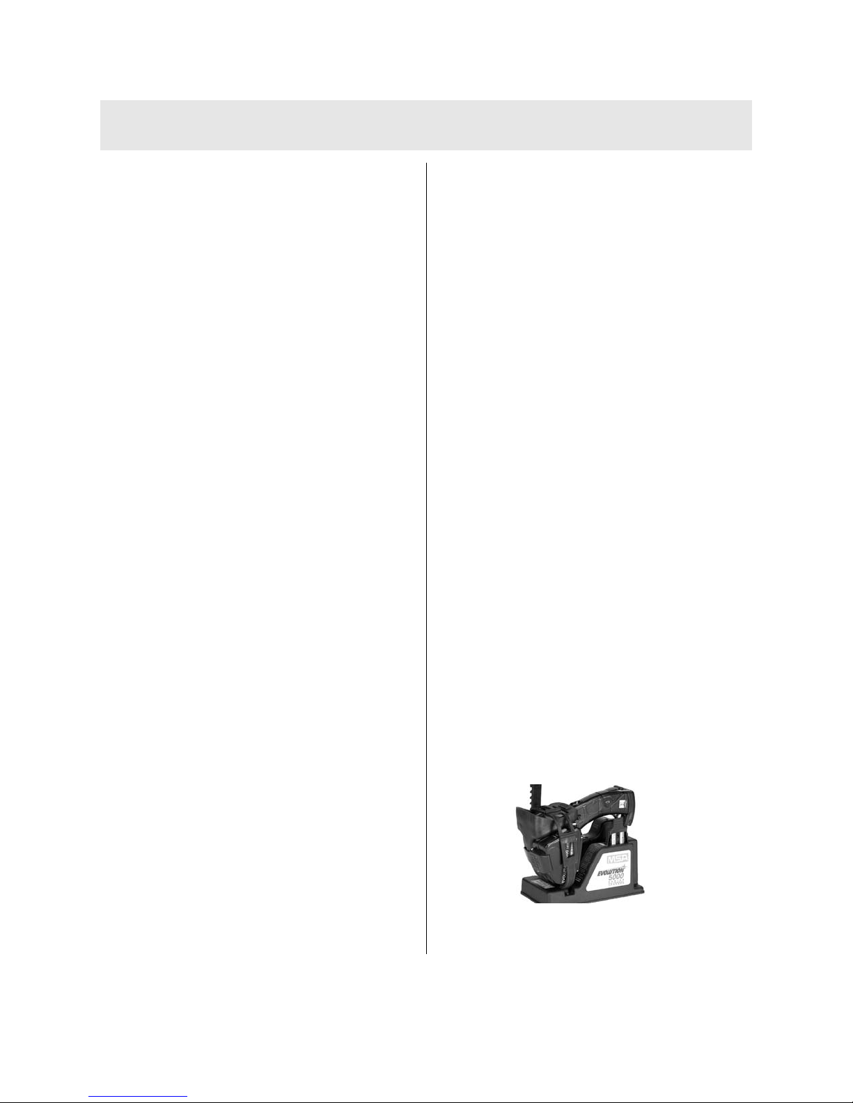
cradle are clean and free from debris (FIGURE 8).
1. Place the handle of the TIC on the alignment
pin, with the display facing inward. Pivot the
camera down until the charging connections
make contact; secure the unit with the straps
on the charging cradle.
2. If charging a spare battery, place the battery
into the slot provided and secure it with the
rubber retainer.
The power LED indicator should always remain
green when the power source is ON and properly
connected. When the Truck-Mounted Charging
System is correctly installed, the status indicators
will light as follows:
Power Status LED Indicators
OFF System Fault
GREEN Power On/ System Operational
Any LED indication other than those listed indicates faulty
operation and the unit must be returned to MSA for service.
Battery LED Indicators
OFF No Battery Installed
GREEN Charge Completed
FAST BLINKING
GREEN Charging
SLOW BLINKING
GREEN Charge Pending
RED Fault
Any LED indication other than those listed indicates faulty
operation and the unit must be returned to MSA for service.
Figure 8.
Universal Charger/Camera
Engagement Sequence
EVOLUTION 5000 SERIES UNIVERSAL TRUCK-
MOUNTED CHARGING SYSTEM OPERATION
Page 15

NOTE: For optimal performance, the battery
charger should be operated at temperatures between 50 to 85° F (10 to 29° C).
Charging batteries outside this temperature range may result in a charging error
and/or premature battery degradation.
Charging batteries in environments greater
than 100° F (38° C) may result in premature termination of charge.
The charging cycle takes approximately 2-1/2
hours to completely charge a single battery or
five hours when charging two completely
discharged batteries.
Figure 11.
Figure 10.
Figure 9.
11
Page 16

Operation
Getting Started
The Evolution 5000 Series Universal TruckMounted Charging System must be correctly
installed before use. Read all installation
instructions thoroughly before starting actual
installation.
Carefully follow all instructions provided with this charger. This charger
will perform as designed only if
installed, used, and maintained properly; otherwise, it may fail to operate
properly and result in serious personal injury or death.
Use eyewear or face protection to
avoid eye injury during installation;
failure to do so may result in serious
personal injury.
What you will need:
• Electric drill
• #7 (.201) drill bit, 9/32 (0.281) drill bit
• 1/4-20 tap
• #2 Phillips head screwdriver
• Stainless steel 1/4- 20 bolts (4)
• 5-amp in-line fuse
• Master ON/OFF switch
• Strain relief bushing for power supply cable
• Installation hardware kit (provided).
Installation Guidelines
Select a large flat surface area for mounting that
allows easy access for Evolution 5200 TIC storage
and adequate cable length for electrical
connections. Take care to install the charger in an
area protected from direct water spray and
extreme temperature conditions.
Mounting Hanging Channels
1. Drill two holes in both Unistrut channels (A in
FIGURE 8), using a 9/32 (.281) drill.
• Drill mounting holes, 1-1/2 inches in
from outside edges of channels.
2. Place top channel on the cab wall,
approximately four inches away from
overhead obstructions.
3. Using a Unistrut channel as a template, drill
two holes into cab wall with a #7 (.201) drill.
4. Tap both holes for 1/4-20 mounting bolts.
5. Position bottom channel on cab wall, 6-1/2
inches away from center of top channel.
6. Repeat steps 3 and 4 to mount bottom
channel.
7. Bolt both channels in-place with stainless
steel 1/4-20 bolts.
Mounting the Universal Truck-Mounted
Charger to Channels
1. Slide Unistrut spring nut (B in FIGURE 8) into
channel and rotate 90° to seat nut in channel
V-groove. One nut is required for the top
channel and two for the bottom channel.
2. Place the stainless steel bolts (C in
FIGURE8) through the mounting holes
molded into the charger.
3. Place the neoprene rubber washer (D in
FIGURE 8) over the bolt, align bolt with
spring nut and tighten.
NOTE: If mounting the charger vertically, use
the two longer stainless steel bolts on
the bottom and add a second
neoprene washer to each of the
bottom two bolts.
"
WARNING
12
EVOLUTION 5000 SERIES UNIVERSAL TRUCK-
MOUNTED CHARGING SYSTEM INSTALLATION
Page 17

13
Electrical Connections
Power Requirements
The Truck-Mounted Charging System can
consume enough current to eventually fully drain
the vehicle's battery, if the vehicle stands for
longer than a 12-hour period without supplemental
battery charging.
Therefore, it is recommended that the charger be
installed using any master ON/OFF switch where
power comes directly from the battery,
supplemental charger or connected to AC power
via a shoreline when the vehicle is stored.
Electrical Specifications
INPUT VOLTAGE
12.5 to 26.0 VDC (Fused at source)
RANGE
INPUT CURRENT
Less than 2.0 Amps DC
NORMAL BATTERY
2.5 Hours
CHARGE TIME
.
Installation
1. Connect the positive lead (red) on the
prepared wire end of the power supply line to
a fused, in-line connection with a master
switch. Connect to the switched side of
ignition or power source.
2. Connect the negative lead (black) of power
supply line to a confirmed ground.
3. With power source ON, confirm that the
power LED light is GREEN. If any other result
occurs, see "Troubleshooting Guidelines" in
the "Maintenance, Troubleshooting and
Service" section of this manual.
Page 18

14
Thermal Imaging Camera Warranty
Component Warranty Period Maintenance
Product Description Warranty Period Routine Air Mask Maintenance
1. Express Warranty
MSA warrants that this product and its accessories are free from mechanical defects or faulty workmanship as prescribed in the chart below,
provided they have been installed, used, and maintained in accordance with the instructions and/or recommendations contained in the
instructions delivered with the equipment. MSA shall be released from all obligations under this warranty in the event repairs or modifications
are made by persons other than its own or authorized service personnel. No agent, employee or representative of MSA has any authority to
bind MSA to any affirmation, representation or warranty concerning the goods sold, and unless an affirmation, representation or warranty made
by an agent, employee or representative is specifically included within the written agreement for the goods sold it shall not be enforceable by
the original end-user. MSA makes no warranty concerning components or accessories not manufactured by MSA, but will pass on to the
original end-user all warranties of manufacturers of such components. THIS WARRANTY IS IN LIEU OF ALL OTHER WARRANTIES, EXPRESS,
IMPLIED OR STATUTORY, AND IS STRICTLY LIMITED TO THE TERMS HEREOF. MSA SPECIFICALLY DISCLAIMS ANY WARRANTY OF
MERCHANTABILITY OR OF FITNESS FOR A PARTICULAR PURPOSE.
Products covered by this Express Warranty include the Evolution 5200, Evolution 5200HD, Evolution 5600, Evolution 5800 and ThermalTrac
Thermal Imaging Cameras (TICs). All warranty periods referenced below are from the date of sale to the original end-user unless otherwise
noted.
Camera Core 2 years
Housing and all non-camera
core components
Truck/Wall/Desktop Chargers, External
Receivers and Transmission Equipment
Replacement Parts / Repairs (non-warranty) 90 Days from date of repair
Factory Upgrades
2. Extended Service
MSA offers an Extended Service contract for TICs at the customer’s request. Details are listed on the reverse of this page.
Contact MSA Fire Service Customer Service (1-800-MSA-2222) for additional information and arrangements.
3. Loaner Cameras
MSA does support a loaner camera program for customers when deemed necessary (extended repair time, critical equipment
replacement, etc.). The loaner camera will not necessarily be the exact model that it is replacing. Contact MSA Fire Service Customer
Service (1-800-MSA-2222) for additional information and arrangements.
4. Exclusive Remedy—It is expressly agreed that the Original end-user’s sole and exclusive remedy for breach of the above warranty, for
any tortious conduct of MSA, or for any other cause of action, shall be the repair and/or replacement, at MSA’s option, of any equipment or
parts thereof, that after examination by MSA are proven to be defective. Replacement equipment and/or parts will be provided at no cost to
the Original end-user, F.O.B. Original end-user’s named place of destination. Failure of MSA to successfully repair any nonconforming
product shall not cause the remedy established hereby to fail of its essential purpose.
5. Exclusion of Consequential Damages—Original end-user specifically understands and agrees that under no circumstances will MSA be
liable to Original end-user for economic, special, incidental, or consequential damages or losses of any kind whatsoever, including but not
limited to, loss of anticipated profits and any other loss caused by reason of the non-operation of the goods. This exclusion is applicable to
claims for breach of warranty, tortious conduct or any other cause of action against MSA
Note: This Bulletin contains only a general
description of the products shown. While uses
and performance capabilities are described,
under no circumstances shall the products
be used by untrained or unqualified individuals
and not until the product structions
including any warnings or cautions
provided have been thoroughly
read and understood. Only they
contain the complete and detailed
information concerning proper use
and care of these products.
10048052, Rev 8
ID 3400-41-MC / July 2008
© MSA 2008 Printed in U.S.A.
Corporate Headquarters
P.O. Box 426, Pittsburgh, PA 15230 USA
Phone 412-967-3000
www.MSAFire.com
Fire Service Customer Service
Phone 1-877-MSA-FIRE
Fax 1-800-967-0398
MSA Canada
Phone 1-800-MSA-2222
Fax 905-238-4151
MSA Mexico
Phone (52) 55 2122 5770
Fax (52) 55 5359 4330
MSA International
Phone 412-967-3354
Fax 412-967-3451
1 year
1 year
90 Days or remainder of existing
warranty, whichever is longer
Offices and representatives worldwide
For further information:
MSA requires that the TIC and accessories be
installed, used, and/or maintained as specified in
the product instructions. All TICs and accessories
sent in for warranty repair will be inspected for
signs of excessive rough handling and operation
significantly beyond specifications in the
instructions. The warranty coverage is for
material defects and/or faulty workmanship only.
Repair and labor required fo r normal wear and
tear are not covered under the warranty and are
the responsibility of the original end-user.
Page 19

15
Evolution®Thermal Imaging Camera
Extended Service Application
Submit this completed form to:
Attention: Fire Service Customer Service Center
Evolution TIC Extended Service Program
Pittsburgh, PA 15230-0426
One application must be submitted for EACH Evolution TIC. Phone 1-800-MSA-2222 for assistance in completing this form.
1. Extended warranty requests MUST be exercised within the first 6 months from the date of manufacture. The last three characters
(MYY, or “month-year-year”) of the TIC’s serial number (located in the battery compartment of the TIC) will dictate this time-frame
(XX-XXXX-MYY).
2. Extended warranty will lengthen warranty coverage up to 12 months after the standard warranty would expire.
(Total coverage for the camera core would be 36 months; total coverage for the rest of the camera would be 24 months.)
3. Extended warranty and standard warranty both begin from the date of purchase by the end user.
4. This Extended Warranty program applies only to MSA Evolution Thermal Imaging Cameras. Consumables, battery chargers
and accessories are not covered.
Please print legibly
Company/Department Name
Contact Name Title
Phone Fax Email
MSA
PO Box 426
(or Fax 1-412-967-3053)
MAILING ADDRESS:
Street/PO Box
City
State/Province Zip/PC
Please extend the service on the following MSA Evolution Thermal Imaging Camera:
Evolution 5200 TIC Evolution 5200HD2/ThermalTrac TIC Evolution 5600 TIC Evolution 5800
Serial # (located in TIC battery compartment)
This TIC was purchased from (insert MSA distributor company name) on our
Purchase Order # dated Distributor Invoice # dated
Purchase Order # enclosed
Print Name
Authorized Signature
1 year extended service - US $1000
SHIPPING ADDRESS:
Street/PO Box
City
State/Province Zip/PC
Page 20

16
GENERAL MAINTENANCE
After each use, inspect:
• the Evolution 5200 TIC for structural, heat
and/or chemical damage
• the mechanical hardware to ensure no
screws are loose
• all lenses for heat damage, chemical
damage, cracks and breaks
• to ensure that all warning labels are intact
• battery - see "Battery Care and Installation"
NOTE: Thermal Imaging Cameras not meeting
the above inspection must be removed
from service until the proper repairs are
made by MSA.
• charger and TIC LEDs for proper indication
that the system is operating properly.
Cleaning
After each use, clean all external surfaces (case,
base, visor, lens, window and straps) by wiping
with a solution of mild detergent and warm water.
Dry with a soft, lint-free cloth, to avoid scratching
the optical surfaces.
Periodically check connector terminals, video
socket, ON/OFF switch, locking latch and hinge
for contamination. Clean with a soft, lint-free cloth.
Do not remove the thermal imaging
camera cover or casing as the system
operates on high voltage. Only
authorized personnel may service the
unit.
FAILURE TO FOLLOW THE ABOVE
WARNING CAN RESULT IN SERIOUS
PERSONAL INJURY OR DEATH.
TROUBLESHOOTING THE TRUCKMOUNTED CHARGING SYSTEM
Troubleshooting Guidelines
SYMPTOM PROBLEM/SOLUTION
NO LEDs LIT
Check power connections.
Is power available?
Is the positive power lead connected
to the positive terminal?
External in-line fuse blown.
Replace fuse
Internal fuse blown. Replace fuse.
POWER LED STATUS
No batteries installed in the camera.
IS GREEN & CAMERA
Verify that there are good batteries in
BATTERY LED DOES
the camera
NOT LIGHT WHEN
Bad connection to the camera.
CAMERA IS PLACED
Make sure charger contacts are clean
IN CHARGER
and unbent. A small amount of contact
cleaner, such as WD-40, can be used
to clean charger and camera charging
contacts. Reseat firmly to
ensure connection .
POWER LED STATUS
Inspect battery contacts for dirt,
IS GREEN AND
corrosion or damage. Clean contacts
EXTERNAL BATTERY
or replace battery. Inspect the
LED DOES NOT LIGHT
contacts of the battery charger.
WHEN BATTERY IS
Verify they are clean, unbent, and
PLACED IN CHARGER
move down and spring back.
BATTERIES DO NOT
Out of operating temperature range.
FULLY CHARGE
Check that temperature of
environment and /or batteries is within
recommended operating range
Power source is noisy. Ensure power
hookup cable is connected to a clean
source without excessive voltage
spikes.
It is possible that charge can be terminated abnormally. While this condition is rare, it can occur because of
external in-band noise that may reach
the charger electronics. In the unlikely event that charge is falsely terminated because of noise, the battery
may not fully charge. Always use the
camera battery gauge as an indicator
of battery condition.
Do not use solvents or paint thinners
to clean the Thermal Imager; otherwise, the protective case may become
degraded.
"
CAUTION
"
WARNING
"
WARNING
MAINTENANCE AND ADJUSTMENTS
Page 21

17
SERVICE
If your Evolution 5200 Thermal Imaging Camera
(TIC) is in need of service or repair, please contact
the MSA Service Center at 1-877-MSA-FIRE.
Describe the problem to the Representative as
completely as possible.
1. Verify with your Representative that the
product should be returned to MSA.
2. Before returning the product, decontaminate
and clean your Thermal Imaging Camera to
remove any hazardous materials that may
have settled on the product during use.
• Laws and/or shipping regulations prohibit the
shipment of hazardous or contaminated
materials.
• Products suspected of contamination will be
professionally decontaminated at the
customer's expense before servicing.
• Ship returned products (including those under
warranty) with pre-paid transportation
charges; MSA cannot accept returned goods
on a freight-collect basis.
Field Repairs and Maintenance
NOTE: Only remove the Truck-Mounted Charging
System's back cover in an ESD-protected
area with personal grounding system
(e.g., grounded wrist strap).
Internal PCB Fuse Replacement
Power LED will not light and other
troubleshooting guidelines do not resolve
the problem.
1. Remove charger from mounting brackets.
Using a screwdriver, remove the three
retaining clips from the plastic bosses and
remove the back cover.
2. Disconnect the power hookup cable by
disconnecting the Phoenix connector from the
plug-in receptacle on the upper right side of
the printed circuit board panel.
3. The internal printed circuit board fuse is
located next to the Phoenix connector on the
circuit board. Remove the fuse using the
plastic, nonconductive tweezers and replace
it with a new fuse (P/N 10041101, package
of five)
4. Reconnect the power hook-up cable to
the Phoenix connector and replace the
back cover. Secure the cover with the
retaining clips and bolt it back to the
mounting brackets.
Figure 12. Location of Power Cable, Phoenix Connector, and Internal Fuse
Page 22

18
Page 23

19
PART SPARE PART
NUMBER
10041100 Charger 110 VAC with Cigarette Lighter Adapter
10038412 Lithium Ion Battery
10067565 Evolution 5000 Series Universal Truck-Mounted Charging System
10039516 Wrist Strap
10039515 Shoulder Strap
10040226 Retractable Lanyard
10040005 Caribiner
10039603 Sun Shroud
10038970 Disposable Display Covers
10067707 Non-Charging Mounting Bracket
10040223 Carrying Case
10040229 Tripod Mount
10018996 Tripod Kit
10040004 Video Out Cable SMA to BNC
10020290 10 Foot Auxiliary BNC Cable
10059512 Instruction Manual
10041101 Fuses, Truck-Mounted Charger (package of five)
10040222 Evolution 5000 Series Mounting Kit
10062184 Label Kit, Reflective ID
EVOLUTION 5000 SERIES TIC SPARE PARTS LIST
 Loading...