

Page 1

User Instructions
Dyna-Glide™
Climbing Protection Systems
Model/Modelo/Modèle
Order No.: R621501/03
Print Spec.: 10000005389 (E)
CR 800000031315
MSAsafety.com
Page 2
WARNING
PLEASE READ THESE INSTRUCTIONS CAREFULLY AND COMPLETELY BEFORE USING THIS
PRODUCT. WHEN USED AS INSTRUCTED THE GLIDELOC RAIL SYSTEM WILL REDUCE THE
USER’S RISK OF INJURY FROM POTENTIALLY HAZARDOUS FALLS. USE OF THIS PRODUCT
WITHOUT READING AND FOLLOWING THE INSTRUCTIONS MAY RESULT IN SERIOUS OR
FATAL INJURY.
IT IS THE RESPONSIBILITY OF THE USER AND THE USER’S MANAGEMENT TO BE CERTAIN
THE USER IS THOROUGHLY TRAINED IN AND COMPLIES WITH THE PROPER INSTALLATION,
OPERATION AND LIMITATIONS OF THIS PRODUCT AS WELL AS CAREFUL INSPECTION,
MAINTENANCE AND STORAGE OF THE PRODUCT BEFORE AND AFTER USE. TRAINING AND
INSTRUCTION REVIEW SHOULD BE REPEATED AT REGULAR INTERVALS BY THE USER AND
THE USER’S MANAGEMENT. THE BUYERS AND USERS OF THIS PRODUCT ASSUME ALL
RESPONSIBILITIES FOR SAFETY AND USE NOT IN ACCORDANCE WITH THESE INSTRUCTIONS. IT MAY BE A VIOLATION OF FEDERAL, STATE OR LOCAL LAWS TO USE THIS
PRODUCT IN A MANNER INCONSISTENT WITH ITS LABELING AND INSTRUCTION.
1000 Cranberry Woods Drive
Cranberry Township, PA 16066
USA
Phone 1-800-MSA-2222
Fax 1-800-967-0398
For your local MSA contacts please go to our website www.MSAsafety.com
©
MSA 2019. All rights reserved
Page 3

Contents
1 Description of the Dyna-Glide™Climbing Protection Systems ............................................. 4
1.1 Rail Sections ..................................................................................................................................... 5
1.2 Rail Connector Assemblies ............................................................................................................... 5
1.3 Mounting Assemblies ........................................................................................................................ 8
1.4 Dyna-Glide™ Fall Arrester .............................................................................................................. 12
1.5 End Stop Assemblies ...................................................................................................................... 13
1.6 Body Supports ................................................................................................................................. 15
1.7 Accessories ..................................................................................................................................... 15
2 Planning the Installation ......................................................................................................... 18
3 Making the Installation ............................................................................................................ 18
3.1 Equipment Required ........................................................................................................................ 18
3.2 Personnel Required ......................................................................................................................... 18
3.3 Installers’ Personal Safety Equipment ............................................................................................. 19
3.4 Preparation of Materials at the Installation Site ............................................................................... 20
3.5 Assembly Sequence ........................................................................................................................ 21
3.6 Torque Range for Tightening Nuts .................................................................................................. 21
3.7 Coupling Rails and Mounting to Ladder Rungs ............................................................................... 22
3.8 End Stop Installation ....................................................................................................................... 23
3.9 Folding Footrest Installation ............................................................................................................ 23
3.10 Final Inspection of Rail Assembly ................................................................................................... 24
Contents
4 Use of Dyna-Glide System ......................................................................................................25
4.1 Body Support ................................................................................................................................... 25
4.2 Carabiner and Fall Arrester ............................................................................................................. 25
5 Inspection and maintenance .................................................................................................. 27
5.1 Inspection Prior to Use .................................................................................................................... 27
5.2 Rail Inspection Checklist ................................................................................................................. 27
5.3 Inspection of Rail Connectors and Mounting Assemblies ............................................................... 27
5.4 Inspection of End Stops .................................................................................................................. 27
5.5 Inspection of Fall Arrester ............................................................................................................... 28
5.6 Inspection of Folding Footrest ......................................................................................................... 28
5.7 Inspection of Body Support and Carabiner ..................................................................................... 28
6 Parts List for Assemblies ....................................................................................................... 29
7 Warranty ................................................................................................................................... 31
US
Dyna-Glide™
3
Page 4

Description of the Dyna-Glide™Climbing Protection Systems
1 Description of the Dyna-Glide™Climbing Protection Systems
MSA Dyna-Glide™ Climbing Protection Systems are used to prevent and/or arrest falls from heights and
facilitate the climber’s performance of work. The systems are used for mounting to already-installed
ladders, to corners of lattice towers, and to other suitably strong structures which must be climbed.
This manual deals only with systems, which are center-mounted to the rungs of vertical fixed ladders. This
is the most prevalent type of system. However, by substitution of different mounting assemblies, DynaGlide systems may be attached to almost any structure that is permissible to climb. Systems may also be
constructed to continuously protect the climber when traveling horizontally, and around curves, corners
and obstacles in the climb path.
A properly installed, used and maintained Dyna-Glide system will help to stabilize a climber at a work
position, will permit restricted travel of the climber along the rail, and will automatically stop an accidental
fall within inches. The Dyna-Glide system may be used by more than one person at a time.
A complete system consists of:
a) standard joinable straight rail sections of length 7 feet 4-3/16 inches (2240 mm);
b) if needed, custom (built to special specification) curved rail sections of the concave, convex or
compound type;
c) Standard rail connector assemblies used to couple rail sections together;
d) Standard mounting assemblies for attachment of rail sections to fixed ladders and other structures;
e) If needed, custom (built to special specification) mounting assemblies for attachment of rail sections
to structural members of unusual configuration;
f) A Dyna-Glide fall arrester which engages the rail sections, permits the climber to work position,
permits travel along the rail, and stops against a rail notch in case the climber falls;
g) End stops to prevent the fall arrester from slipping out of the bottom or top end of a string of rail
sections;
h) A full body harness; and
i) If needed, a variety of accessories which enhance mobility and provide continuous protection, conve-
nience and comfort.
US
4
Dyna-Glide™
Page 5

Description of the Dyna-Glide™Climbing Protection Systems
1.1 Rail Sections
The rail sections are made of either hot galvanized steel or stainless steel. They have a C-profile cross
section with rectangular cut outs (slots) at 5.51 inch (140 mm) intervals for coupling adjacent rail sections
together and for connection of the rail sections to mounting assemblies. Notches are located at 5.51 inch
(140 mm) intervals to serve as stops for the fall arrester. The standard length of a rail section is 7 feet 4-3/
16 inches (2240 mm) See Figure 1.
3
2
Fig. 1 Notched straight rail section (P/N 506270. GALV.)
Front View Top View
2 Slot 1 Rail Section
3 Notch
Rail sections may be curved to go around objects in the climb path or to bridge between two straight runs
of rail that form an angle with each other. Curved rail sections may have concave, convex or compound
curvature.
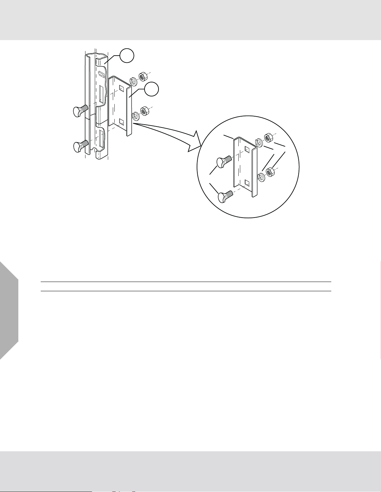
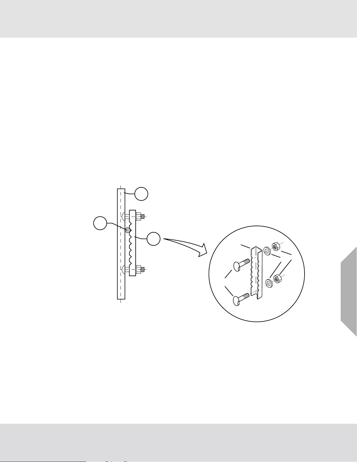
1.2 Rail Connector Assemblies
Rail connectors are used to fasten the rail sections together. These units may be made of stainless steel or
hot galvanized steel. One rail connector assembly is required to fasten together one pair of adjacent rail
sections. The assembly consists of a connector plate and two each bolts, nuts, and lock washers. See
Figure 2. During the installation of the rail system it is critically important that the butt joint between
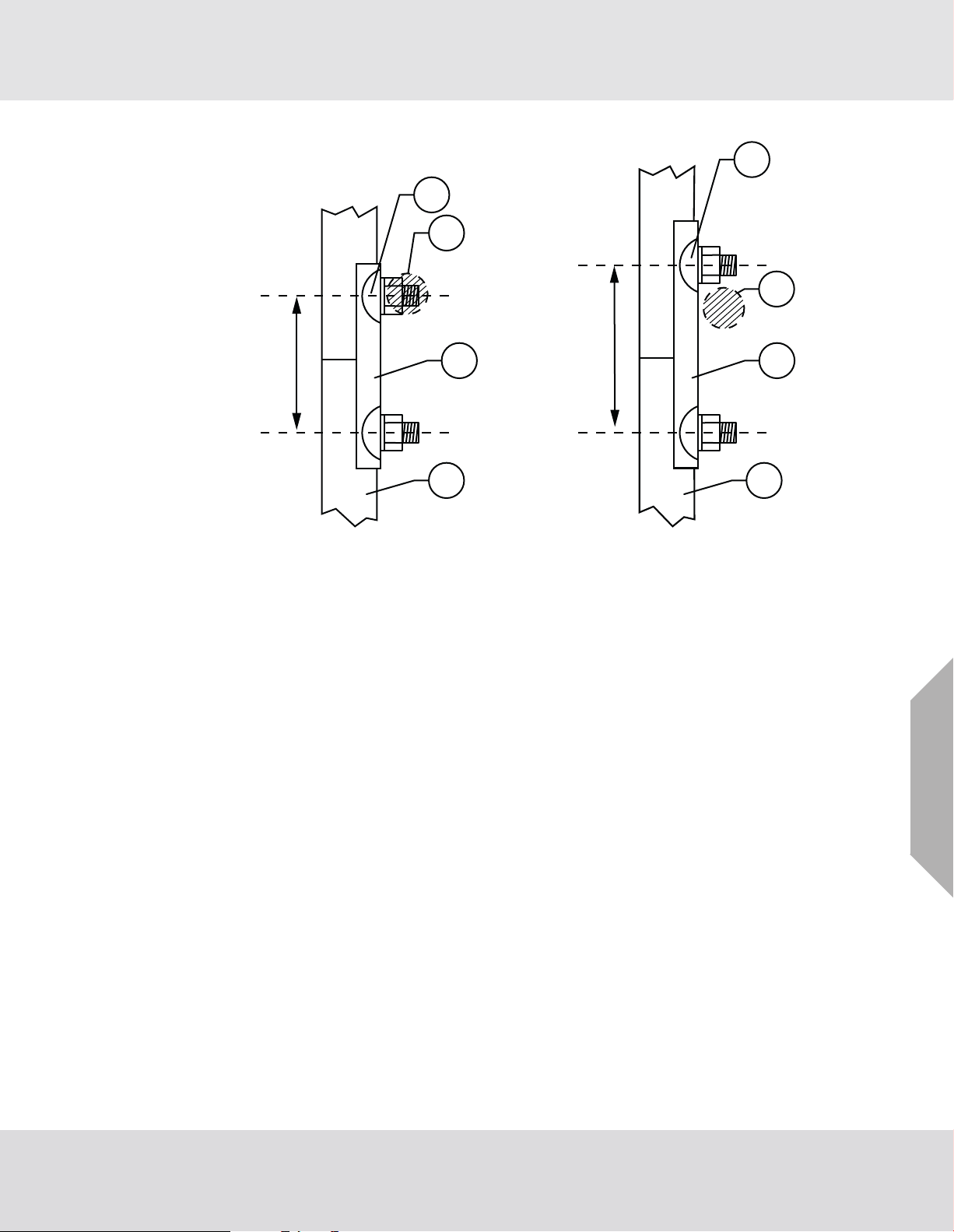
adjacent rail sections is very tight and secured by the rail connector assembly. In case an interference
occurs between the connector plate bolt and a ladder rung (as shown in Figure 3, Rail connector
assembly), then a special rail connector assembly (P/N 506329) is used. This special assembly has a
longer connector plate (P/N 621496) which allows shifting the bolt locations to eliminate the interference.
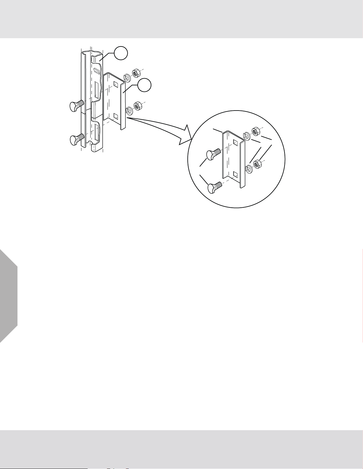
See Figure 3, Special rail connector assembly and Figure 4.
1
US
Dyna-Glide™
5
Page 6
Description of the Dyna-Glide™Climbing Protection Systems
1
2
a
b
c
d
US
Fig. 2 Rail connector assembly (P/N 506271. GALV.)
Installation diagram Rail connector assembly
1 Rail section (P/N 506270) a Connector plate (P/N 621270)
2 Rail connector assembly (P/N 506271) b Bolts (P/N 621267)
c Lock washers (P/N 621268)
d Nuts (P/N 621266)
Note: See Section 6.0 for complete parts list for all assemblies.
6
Dyna-Glide™
Page 7
Description of the Dyna-Glide™Climbing Protection Systems
1
2
4
3
A
5
2
4
6
B
Fig. 3 Rail connector plate bolt - rung interference
Rail connector assembly Special rail connector assembly
1 Connector plate bolt 4 Rail section
2 Ladder rung (Note interference) 5 Connector plate bolt (shifted to avoid rung)
3 Connector plate (P/N 621270 GALV.) 6 Connector plate (P/N 621496 GALV.)
A 4.25 in. B 5.50 in.
US
Dyna-Glide™
7
Page 8
Description of the Dyna-Glide™Climbing Protection Systems
1
2
a
b
c
d
US
Fig. 4 Special rail connector assembly (P/N 506329. GALV.)
Installation diagram Special rail connector assembly (P/N 506329,
1 Rail section (P/N 506270) a Special connector plate (P/N 621496)
2 Rail connector assembly (P/N 506329) b Bolts (P/N 621267)
1.3 Mounting Assemblies
A variety of standard mounting assemblies are available to attach rail sections to the structure which is to
be climbed. In general, all mounting assemblies have a bracket that is shaped and sized to mate with
certain common structural members. The mounting interface with the rail section is always a standard bolt
connection. However, structural members can take on a variety of shapes, sizes and orientations.
Therefore, a variety of mounting brackets is necessary. Custom mounting assemblies may be ordered built
to special specification. At least two mounting assemblies are always required for each rail section and
these must be spaced apart by no more that 66.14 inches (1680 mm) Although this manual deals only with
rung mounting of rails to fixed ladders, several types of mounting assemblies are described below in order
for the user to plan for future installations.
GALV.)
c Lock washers (P/N 621268)
d Nuts (P/N 621266)
8
Dyna-Glide™
Page 9
Description of the Dyna-Glide™Climbing Protection Systems
a
b
c
d
3
2
1
1.3.1 Rung Mounting Assemblies
Fixed ladders are the most common of all structures to which rail systems are mounted. Fixed ladders are
rigidly anchored to other structures. The ladder normally has rungs with diameter up to 1 1/4 inches (32 mm)
and width between side rails of 12-18 inches (305 mm - 457 mm)
To comply with USA Federal OSHA requirements, rungs must be a minimum of 16 inches wide. The DynaGlide rail sections are normally mounted in the center of the rungs - provided this leaves enough space on
each side to easily place the foot on the rungs even when winter work boots are being worn. The DynaGlide rail is 1.96 inches (50 mm) wide. Assuming a winter boot width to be 5 inches, the rung width must be
at least 14 inches.
Rungs are usually of circular cross-section, although some are angle, rectangular bar or channel. The
standard rung mounting assembly is suitable for rungs of circular cross-section and right angle. The main
part of the standard assembly is an alligator clamp (rung mounting assembly) which is bolted to the rail with
two each bolts, nuts and lock washers as shown in Figure 5.
For instances in which the ladder rung is less than 14 inches in width, the standoff rung mounting assembly
can be used to improve climbing ease. This assembly provides means for attachment of the rail section to
the ladder rungs while spacing the rail section 2.25 inches (57.2 mm), forward of the rungs thereby providing
a wider space for the foot. See Figure 6.
Fig. 5 Rung mounting assembly (P/N 506273. GALV.)
Installation diagram Rung mounting assembly
1 Ladder rung a Rung clamp (P/N 621271)
2 Rail section (P/N 506270) b Bolts (P/N 621267)
3 Rung mounting assembly (P/N 506273) c Lock washers (P/N 621268)
d Nuts (P/N 621266)
Dyna-Glide™
US
9
Page 10
Description of the Dyna-Glide™Climbing Protection Systems
2
3 1
b
a
d
g
f
c
e
f
g
US
Fig. 6 Rung mounting assembly - Standoff (P/N 506325. GALV.)
Installation diagram Rung mounting assembly - Standoff (P/N 506325)
1 Ladder rung a Angel Bracket - Standoff (P/N 621497)
2 Rail section (P/N 506270) b Bolts (P/N 621267)
3 Rung mounting assembly (P/N 506273) c Flat washer (P/N 621465)
d Rung clamp - Standoff (P/N 621484)
e Bolts (P/N 621269)
f Lock washers (P/N 621268)
g Nuts (P/N 621266)
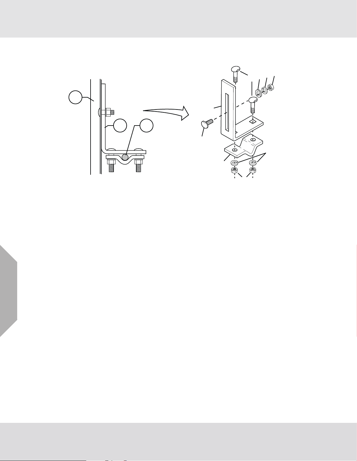
For installation using standoff rung mounting brackets, one base support bracket must be mounted at the
beginning of each vertical run of rail to add additional stiffness. See Figure 7.
10
Dyna-Glide™
Page 11

Description of the Dyna-Glide™Climbing Protection Systems
d
a
b
f
e
f
e
c
e
f
g
d
a
d
b
2
1
3
1
Fig. 7 Base support assembly - Standoff (P/N 506326. GALV.)
Installation diagram Base support assembly - Standoff (P/N 506326)
1 Ladder rung a Angel Bracket - Base Support (P/N 621498)
2 Rail section (P/N 506270) b Rung clamp - Standoff (P/N 621484)
3 Base support assembly - Standoff (P/N
506326)
1.3.2 Angle Corner Mounting Assembly
This assembly provides means for attachment of a rail section to the corner of angle iron structural
members. It consists of a bracket, two clamps for attachment to the edges of the angle, and three each
bolts, lock washers and nuts.
1.3.3 Angle Edge Mounting Assembly
This assembly provides means for attachment of a rail section to the edge of angle iron structural
members. It consists of an edge clamp and one each bolt, lock washer and nut.
1.3.4 Flat Mounting Assembly
This assembly provides means for attachment of a rail section to flat-surfaced structural members. It
consists of a bracket and two each bolts, lock washers, flat washers and nuts.
1.3.5 Column Mounting Assembly
c Stiffening Bar - Base support (P/N 621486)
d Bolts 2 1/2 Inch (P/N 621269)
e Nuts (P/N 621266)
f Lock washers (P/N 621268)
g Flat washer (P/N 621465)
This assembly provides means for attachment of a rail section to poles and pipes. It consists of an
adjustable bracket and five each bolts, lock washers and nuts plus eight each flat washers. Various
bracket adaptations are available, built to special specification, for different column sizes and crosssectional shapes.
US
Dyna-Glide™
11
Page 12

Description of the Dyna-Glide™Climbing Protection Systems
2
4
3
1
1.4 Dyna-Glide™ Fall Arrester
The fall arrester is a glide that engages and travels in the channel of all rail sections. It will allow hands-free
work positioning, restricted travel along the rail, and will arrest a fall within inches by interference of it’s cam
with one of the notches in the rail section. The Dyna-Glide fall arrester can be used on rail, which is installed
either vertically or horizontally and it will travel along curved rail sections provided the rail curve radius is not
too small. It permits ascent without resistance and descent by leaning slightly backward. The Dyna-Glide
fall arrester consists of an aluminum body with a forged steel cam and ring in the vertical plane. See Figure
8. Connection to the body support is accomplished by means of a locking carabiner. See Figure 19.
US
12
Fig. 8 Dyna-Glide™ Fall Arrester (P/N 10183914. GALV.)
Arrow must point up Top View
3 Connection Ring 1 Dyna-Glide Aluminum Body
2 Steel Cam
4 Security Pin
Dyna-Glide™
Page 13

Description of the Dyna-Glide™Climbing Protection Systems
1
2
2
1
1.5 End Stop Assemblies
End stops prevent the Dyna-Glide fall arrester from accidentally slipping out of the top or bottom end of a
string of rail sections. The end stops are available in either gated or ungated models. The gated models
have a pivotable gate, which permits the climber to remove the fall arrester from the rail in a controlled way.
See Figure 9 to 13. The gated models also prevent the climber from inserting the fall arrester in the wrong
direction (upside down).
The ungated model of end stop is rigidly mounted to the rail end and completely prevents the fall arrester
from being taken off the rail system. Obviously, therefore, when the ungated end stop is used at one end of
the rail system, a gated end stop must be used at the other end in order to permit the insertion and removal
of the fall arrester. Alternatively, if an ungated end stop is used on both ends, the fall arrester must be
permanently left on the rail system. This is not recommended unless the system is located in a place, which
is secured from the weather and from unauthorized users.
Fig. 9 End Stop Assemblies (Stainless) - Top End Stop (Gated) (P/N 506274)
1 Rail section
2 End stop assembly
Fig. 10 End Stop Assemblies (Stainless) - Bottom End Stop (Gated) (P/N 506275)
1 Rail section
2 End stop assembly
US
Dyna-Glide™
13
Page 14

Description of the Dyna-Glide™Climbing Protection Systems
2
1
2
1
2
1
Fig. 11 End Stop Assemblies (Stainless) - Top End Stop (Gated) (P/N 506274)
1 Rail section
2 End stop assembly
US
Fig. 12 End Stop Assemblies (Stainless) - Bottom End Stop (Gated) (P/N 506275)
1 Rail section
2 End stop assembly
Fig. 13 End Stop Assemblies (Stainless) - Ungated End Stop (P/N 506312)
1 Rail section
2 End stop assembly
14
Dyna-Glide™
Page 15

Description of the Dyna-Glide™Climbing Protection Systems
2
1
2
12
1.6 Body Supports
The Dyna-Glide Climbing Protection System is designed to be used with a Full Body Harness which
attaches to the fall arrester at chest level.
This full body harness has the benefit of serving a wide range of climber needs in addition to attachment to
the fall arrester. A variety of full body harnesses may be suitable for use in the Dyna-Glide system provided
they have a compatible means of frontal connection to the fall arrester which is located between the waist
and sternum of the climber.
The MSA Dyna-Glide is designed to be used with other MSA-approved products. Use of the Dyna-Glide
with products that are not approved in writing by MSA may adversely affect the functional capability between
system components and reliability of the complete system.
1.7 Accessories
Beyond the basic components described above, several optional accessories are available. These accessories can enhance the climber’s mobility, extend the range of continuous protection, and provide added
convenience and comfort.
1.7.1 Folding Footrest
This is a pedestal, just large enough for both feet, which attaches to a rail section with a hinged bracket that
enables the footrest to be pivoted up, out of the way of the climber, or down to stand on. See Figure 14. The
travel of the fall arrester is not interfered with. The footrest is normally installed at fixed points where there
may be a need to rest or perform work or inspections. It can be mounted at any point on a rail section except
the very ends where a rail connector assembly is installed. It is made from either hot galvanized steel or
stainless steel and is attached to the rail using two each bolts, lock washers and nuts.
Fig. 14 Folding Footrest Assembly (P/N 506384. GALV.)
1 Rail section
2 Footrest assembly
Dyna-Glide™
US
15
Page 16

Description of the Dyna-Glide™Climbing Protection Systems
3
1
2
1.7.2 Ice Scraper
In climates where the rail system may be covered with ice; an ice scraper is recommended to clear ice off
the rail and enable the fall arrester to travel properly. The ice scraper is a lightweight glide with aluminum
body, stainless steel ice chisel and stainless steel grip. See Figure 15. Unlike the fall arrester, it has no
locking mechanism. It is manually pushed up the rail ahead of the fall arrester, cracking off ice on the rail
surface. The following fall arrester can then travel on the rail.
CAUTION
In extreme cases where ice cannot - be adequately removed. the system must not be used
US
Fig. 15 Ice Scraper (P/N 506405)
1 Ice Scraper Body
2 Ice Chisel
3 Grip
1.7.3 Turntable Assembly
This is a stainless steel rotating device that enables the climber to transfer between vertical and horizontal
runs of rail sections without disconnection of the fall arrester. The turntable abuts as many as four rail
sections. The fall arrester may therefore pass through it in as many as four directions (up, down, left and
right). The turntable receives the fall arrester when it enters from any of the adjacent rail sections. By
rotating the turntable receptacle, the fall arrester may then be moved away from the intersection in a
different direction. The turntable receptacle can rotate 90 degrees, enabling the four-way intersection.
CAUTION
When more than one turntable is installed in a Dyna-Glide Rail System, extreme care must be taken to be
sure that the fall arrester cannot be rotated so as to have it re-enter a vertical rail section in the wrong direction and thereby not be able to block a fall.
The turntable can be mounted at the intersection of curved rail sections provided, however, the radius of
curvature of such rail sections is not less than 19.7 inches (500 mm). This feature permits the climber to
negotiate about obstacles.
16
Dyna-Glide™
Page 17

Description of the Dyna-Glide™Climbing Protection Systems
1.7.4 Roundabout Assembly
The roundabout is a device consisting of a trolley that runs on two parallel horizontal rods. The trolley is
vertically mounted and abuts two adjacent vertical rail sections. The trolley has spring - loaded pins, which
permit the fall arrester to be slipped into it and captured until intentionally removed. When the fall arrester
is engaged within the trolley, the trolley and fall arrester may travel together along the horizontal rods and
thereby move in an arc around obstacles without disconnection of the fall arrester. A hand rail and a foot
rail assist the climber in traversing about the obstacle. The parallel horizontal rods may have a stop to align
the trolley with another rail section apart from the one used to enter the trolley with the fall arrester. The
roundabout assembly is used where the radius of movement about obstacles is less than 19.7 inches
(500 mm).
Dyna-Glide™
US
17
Page 18

Planning the Installation
2 Planning the Installation
In the preceding section of this manual we described the many components of the Dyna-Glide system.
Before these can be assembled into a system the requirements which the system must satisfy have to be
determined. This starts by identifying the places, which must be accessed, tbe climbing path, the footing
and band holds for the climber, and the structure to which the rail system will be attached.
Special attention must be paid to the workplace geometry and required mobility of the user. The objective
of the system design is to provide protection throughout the user’s ascent, descent and work. Consideration
must be given to environmental factors and the location and nature of hazards before a plan can be developed which eliminates or effectively controls the user’s exposure to these hazards.
Avoid installation where objects falling from above can strike the climber or damage the rail system. Follow
all utility company rules when installations are made near electrically energized lines. Always have a plan
for rescue of personnel using the rail system.
3 Making the Installation
3.1 Equipment Required
The only equipment, which is normally necessary to make an installation of a rail system to a fixed ladder is:
a) Wrenches, eight inches long open and box ends of 3/4 inches.
b) A bolt bag and rope for conveying the clamps, brackets, bolts, nuts and washers from the ground to
the installer.
c) A pulley and rope for raising rail sections and the bolt bag to the installer.
d) A clamp or lash to temporarily bold a rail section in place until attachment to the rail connector is
made.
e) A full body harness.
f) A work positioning lanyard.
g) A suitable temporary fall arrester/lifeline with anchorage means.
h) A tool belt with separate bags for bolts, nuts and washers.
i) A tape measure.
j) Two-way radios (2) (optional)
k) If required, a miter box for cutting steel rail.
US
3.2 Personnel Required
Two persons are required to make an installation to a fixed vertical ladder. One person (the “climbing
installer”) climbs and installs the rail sections one at a time. The second person is on the ground (the “ground
person”) and deploys materials to the climber.
The climbing installer and the ground person should both be trained and experienced climbers versed in
safety at heights - including rescue procedures. Unless there are other personnel at ground level who are
trained and equipped for rescue, the ground person must be prepared to immediately effect a rescue operation. This includes wearing the proper equipment at all times and having means of calling others for emergency assistance. If the climbing installer and ground person switch roles to spell each other off, then both
must be equipped, trained and fit to assume the duties and responsibilities of both roles.
18
Dyna-Glide™
Page 19

Making the Installation
4
1
2
3
3.3 Installers’ Personal Safety Equipment
The first thing the installers must do is don and put in place their personal protective equipment. This
consists primarily of the climber’s personal fall arrest system but also includes hard hat, gloves, protective
eyewear, safety shoes and other special equipment called for in the circumstances. When anchoring the
temporary personal fall arrest system, the climbing installer should also anchor the pulley and handline for
raising the rails and installation hardware.
Carefully follow the manufacturer’s instructions for anchoring and use of the personal fall arrest system and
materials pulley/handline. The pulley/handline should be rigged so as to permit lifting components to the
climbing installer so they are easily within his reach and can be stabilized by the ground person until
mounted to the structure. See Figure 16.
Fig. 16 Use of Personal Fall Arrest System
1 Pulley/Handline
2 Climbing Installer
3 Personal Fall Arrest System
4 Ground Person
Dyna-Glide™
US
19
Page 20

Making the Installation
3.4 Preparation of Materials at the Installation Site
Locate all rail sections and installation hardware in a dry place outside the zone of any possible trajectory
of tools or materials, which could fall from overhead during the installation. If this is not possible, install
protective netting of proper strength and mesh above where the ground worker may be while assisting the
climbing installer.
Note: In some installations, such as confined spaces underground, the materials must be moved down-
ward. If materials are outside or where they can be contaminated, protect them with tarp and
keep them off the ground with pallets.
Before mounting, clean all parts of any residual foreign matter - especially at the connecting areas. Avoid
contact with mortar, concrete or other materials, which may adhere to surfaces. Remove any such contaminants immediately. The running surfaces for the fall arrester are particularly important to check for foreign
matter. Check all parts for deformations, improper surface finish, alterations and manufacturing defects
which could affect performance or fit.
Segregate all parts and orient rail sections to facilitate connection at the end which is to be uppermost (notch
opening “up”) when being moved for mounting.
CAUTION
US
Always check to be sure the rail notches are up or the fall arrester will otherwise not lock.
Place installation hardware into a bolt bag and/or climber - borne pouches to ease removal for installation
aloft. Consult the installation plan and lay out special rails (e.g. curved sections) in the sequence they will
be installed. Two-way radio contact is very helpful on long runs of rail to coordinate when things such as
special sections are needed next in the installation sequence. Radio contact is also important to keep the
two installers aware of their respective needs or problems and to provide means of communicating safety
hazards or emergencies.
To assist the climbing installer, it is sometimes preferred to pre-assemble some parts on the ground. For
example, the rail connector assembly can be attached (not tightly) to the bottom of a rail section before it is
moved to the mounting point. (Care must be taken to assure the parts do not come loose and fall during
movement.) The climbing installer is thus saved some time and motion in making the first coupling of that
rail section. It is usually not advisable to pre-assemble parts of mounting assemblies on the ground as their
precise location must be decided by the climbing installer.
As an extra precaution, the ground person may install a piece of heavy wire at the top of each rail section
before moving it to the mounting place with the handline. The wire goes through the top slot in the rail, then
around one side of the rail, and is secured by twisting the wire ends together. The wire must not be removed
until the next rail section is properly connected. This helps to remind the climbing installer which end is “up”.
It also prevents the Dyna-Glide fall arrester from slipping out of the top rail and falling to the ground.
Note: During rail installation it is suggested that a fall arrester be mounted on the rail by the climbing
installer and moved upward with each rail section installation to check for misfit rail abutments
and unsatisfactory fall arrester-to-rail interfacing which may require remedy before the installation
is complete.
20
WARNING
The climber must never connect himself to this fall arrester until the entire system installation is completed
and inspected.
Dyna-Glide™
Page 21

Making the Installation
3.5 Assembly Sequence
Assembly of the Dyna-Glide system must start at the bottom of the run and be built upward toward the top.
The first rail section installed should be the one that contains the bottom end stop. Be certain the notches
on the rail point upward (see Figure 1, Item 3) and that the bottom end stop is installed in its proper orientation. See Figure 10 and Section 3.8. Positioning the bottom end stop close to waist level will ease attachment of the Dyna-Glide fall arrester when preparing to climb.
If the first rail section is located near enough to the ground, no climbing or use of the pulley/handline will be
necessary to mount it. However, when mounting the first rail section in an elevated location the worker must
be positioned correctly and securely attached to a fixed anchorage. Install the rail section according to the
procedure in Section 3.7. When changes in direction of the ladder are encountered, and bent rail sections
must be installed, it may be necessary to cut a rail section to shorter than its 88-3/16 inch (2240 mm) length.
When rail sections must be shortened, the proper location of the cut must be determined. The Dyna-Glide
rail sections are made with tabs and slots located on 5-1/2 inch centers. Any cut on a rail section is best
made in 5-1/2 inch increments through the top of the notch closest to the desired length. (See Figure 1,
Item 3) This provides the proper distance of the slot from the end of the rail, which allows a standard
connector plate (Figure 2, Item 2) to fit. This may require shifting the bent rail section up or down a few
inches for proper abutment.
Whenever galvanized rail sections are cut, it is necessary to cover the cut end with a protective coating such
as a 90% zinc galvanizing paint. Cuts should be made with a miter box to assure squareness of ends. The
lead - in edges on the short legs of the C shape should be chamfered 1/16 inch with a file to allow easy
passage of the Dyna-Glide fall arrester through the joint.
For proper installation the Dyna-Glide rung mounting assemblies should be located symmetrically, 11.12
inches to 18 inches (282 mm to 457 mm) from each end of a rail section. The maximum permissible distance
between rung mounting assemblies is 66.14 inches (1680 mm). On rail sections that must be shortened,
the minimum permissible cut length is 44.09 inches (1120 mm). This allows sufficient length to enable the
shortened rail section to be supported by a minimum of two rung mounting assemblies while holding the
mounting assemblies the correct distance from each end.
Once the first rail is mounted, the climbing installer connects to his temporary independent fall arrest system
(not the Dyna-Glide system) and climbs to the upper end of the next installed rail and connects his work
positioning lanyard to the ladder and/or structural member (again. not the just-installed rail). The ground
person connects the handline to the next rail section and raises it to the place where the climbing installer
can make the attachment of the rail connector assembly between the two rail sections. See section 3.7. The
ground person steadies the suspended rail with the handline while the connection is made. Once done, the
climber can disconnect the handline and send the handline end back to the ground person. The climber then
proceeds to attach the mounting assemblies to the rail and ladder in the manner described in section 3.7,
making sure the rail alignment and abutment is correct before tightening the nuts.
US
3.6 Torque Range for Tightening Nuts
The following torque range must be adhered to in order to secure the various fasteners:
a) Rung Mounting Assembly 15-20 lb.-ft.
b) End Stops 20-25 lb.-ft.
c) Rail Connector Assembly 20-25 lb.-ft.
Dyna-Glide™
21
Page 22

Making the Installation
2
3
1
4
5
3.7 Coupling Rails and Mounting to Ladder Rungs
The first step for installing a rail section is to stabilize the rail and install the rail connector assembly shown
in Figure 2. Do not yet tighten the nuts. Next, install the rail mounting assemblies from the lowest to highest
end of the rail section. Do not yet tighten the nuts. Most rail systems will have the rail sections attached to
the ladder rungs by “alligator” rung clamps. However, rails may occasionally need a unique mounting
assembly. In such instances, contact MSA. Special mounting assemblies are not included in this manual.
When attaching a rung (alligator) clamp, hold the rail against the front of ladder rungs and align the clamp
on the back of the rung with teeth engaging the rung. See Figure 5. Insert bolts through the rail slots and
rung clamp holes. Secure with lock washers and nuts. Before tightening nuts, shift the rail into correct alignment with the adjacent rail. See Figures 12,13.
Note: Rung mounting assemblies must be spaced apart by no more than 66 inches (1680 mm) in order
to securely stabilize the rail section.
The second rung clamp is secured in the same way. A final check is made to assure the butt joint between
rails is tight and that the rail alignment is correct. See Figures 17 and 18. Then torque all nuts in accordance
with torque limits in section 3.6.
US
22
Fig. 17 Improper aligment and abutment of adjacent rail sections
Front view Side view
1 Angulation 4 Offset
2 Gap 5 Gap due to Angulation
3 Shift
Dyna-Glide™
Page 23

Making the Installation
1
Fig. 18 Proper aligment and abutment of adjacent rail sections
Front view Side view
1 No Gap, Shift, Offset or Angulation
3.8 End Stop Installation
End stops are installed at the very bottom of the first (lowest) rail section and the very top of the last
(highest) rail section. The bottom end stop is installed at the time the first rail section is installed. The end
stops are marked “Bottom” and “Top”. Be sure they are used in the correct places. See Figure 9 to 13. Use
the bolt, lock washer, flat washer and nut provided in order to secure the end stops in the manner shown.
The lock washer is placed nearest the nut. When finished, the end stop lever must be at the right when
facing the rail. Check to be sure the end stop functions correctly when the fall arrester comes against it.
Rotating the end stop gate should permit the fall arrester to be removed from the rail.
3.9 Folding Footrest Installation
The footrest is attached to the back of the rail by use of two bolts and associated nuts and lock washers. It
is mounted between ladder rungs.
There is a square slot and a rectangular slot in the mounting bracket of the footrest. The square slot is
placed at the lower end. Adjust the elevation of the footrest until there is clearance between the pedestal
and the rung above when the pedestal is pivoted upward. Then fix the footrest in place with the bolts,
lockwashers and nuts. Torque the nuts per section 3.6. Make a final check to be sure the pedestal properly
folds upward and has sufficient clearances. See Figure 14.
US
Dyna-Glide™
23
Page 24

Making the Installation
3.10 Final Inspection of Rail Assembly
After finishing assembly of the rail in accordance with the above, make a final check as follows.
Take a bearing on the vertical alignment of all rail sections. If the alignment is not straight, adjustment must
be made. All abutments of rail sections must be tight. See Figure 17 and 18. If there is misalignment or
gaps between rail sections the fall arrester will not run smoothly and excessive wear of the fall arrester will
result. If one rail section is moved downward to close a gap, all rail sections above it must also be moved
accordingly.
All bolts/nuts must be checked for tightness to the torque ranges in section 3.6. Be sure the lock washers
are in place.
Pass the fall arrester over the entire rail string to be sure it travels smoothly. In particular, check to be sure
it passes the joints of rail sections without hanging up. Be sure all rail sections have the notch opening up.
Otherwise the fall arrester will not stop a fall.
US
24
Dyna-Glide™
Page 25

Use of Dyna-Glide System
4
5
3
8
6
7
2
1
4 Use of Dyna-Glide System
4.1 Body Support
Use the system with the proper body support. We recommend the use of the MSA harness with connection
to the chest D-ring. However, the system may be used with another suitable harness with a D-ring between
waist and sternum level. Special configurations are possible, such as a linkage between two hip D-rings with
an adjustable connector in between for attachment to the fall arrester. Always consult the manufacturer’s
instructions and MSA before using a nonstandard body support and linkage to the fall arrester.
The linkage to the fall arrester must be kept as short as possible. Otherwise, the climber will have to lean
outward too far in order to disengage the fall arrester cam for descent. Keep the body support snug to
prevent slack from increasing this distance.
4.2 Carabiner and Fall Arrester
The carabiner provided is used to link the fall arrester to the frontal D-ring on the body support.
See Figure 19.
Fig. 19 Carabiner
1 Snap Body
2 Engagement with ring on Dyna-Line Fall
Arrester
3 Nose
4 Label
5 Gate
6 Inner Gate
7 Hinge
8 D-Ring Seat
{
{
US
Dyna-Glide™
25
Page 26

Use of Dyna-Glide System
To Unlock and Open Gate
A. Rotate gate 90 degrees about its axis (unlock)
B. Depress gate until it pivots about hinge (open)
To Close and Lock Gate
C.Release gate and it should swing back and contact nose (close)
D. Gate should rotate 90 degrees and engage nose (lock)
CAUTION
Gate should not open under pressure from any direction unless unlocked. If this condition is not met or if
any steps A, B, C, or D cannot be performed properly, remove carabiner from use.
Note: Lubricate area about binge and inner sleeve (on both sides of snap).
Insert the fall arrester into the rail section by opening the end stop gate. Be sure the engraved arrow on the
fall arrester points up in the direction of the arrow and that the security pin is to the right. See Figure 8. Attach
the carabiner to the body support frontal D-ring and then to the ring on the fall arrester.
The climber can now ascend without any resistance. In order to descend, the climber must lean away from
the rail to release the cam on the fall arrester so it will pass the notches in the rail.
If the climber intends to work position during the climb, he should carry a work positioning lanyard of proper
length with him. If he intends to dismount from the rail at any point he must have auxilliary fall arrest equipment for doing so (e.g. a shock absorbing lanyard or a rope grab and installed lifeline). Always anchor and
connect the body support to such equipment before attempting to disconnect from the Dyna-Glide system.
Remove the fall arrester from the rail when all work is complete. It should not be left in the weather or for
someone else to use without proper instruction or authorization.
US
26
Dyna-Glide™
Page 27

Inspection and maintenance
5 Inspection and maintenance
5.1 Inspection Prior to Use
Before each use, inspect the fall arrester, carabiner, body support and end stops. During ascent/descent,
check the rails, rail connectors, and mounting assemblies to be sure they are intact and tight. Look for
excessive wear, damage, alteration, missing parts, corrosion and foreign matter that may impair proper
function. The rail sections and their connections must be formally inspected by a competent person or qualified engineer at least every six months and immediately after experiencing any impact loading. Inspections
should be logged, records preserved and made available for examination upon request.
5.2 Rail Inspection Checklist
a) Check for smooth travel of the fall arrester. If it sticks, remove the rail section where this occurs or
make the needed adjustments at joints.
b) Check tightness and alignment of butt joints between rail sections. See Figure 17 and 18. Make the
necessary adjustment. This may necessitate adjusting several rail sections after the first joint is
corrected. Be sure alignment of rails is preserved.
CAUTION
Use an auxiliary fall arrest system and work positioning lanyard when loosening rail sections for adjust-
ment. Do not rely on the Dyna-Glide fall arrester during such operations.
c) Check for corrosion. If excessive corrosion is evident, replace the rail section.
d) Remove any foreign matter from the rail surface.
e) Check for build up of zinc on the bottom end of rail sections that will cause excessive gap in rail joints.
Remove buildup with hand file as necessary but do not cut fully through protective zinc layer.
5.3 Inspection of Rail Connectors and Mounting Assemblies
a) Check for tightness of all nuts/bolts. Torque requirements are in section 3.6. Replace bolts and nuts
with fouled threads.
b) Check for presence and proper placement of lock washers.
c) Check for damage to any plates, brackets or clamps and replace damaged units. Two mounting
assemblies must be present for every rail section longer than 48 inches.
d) Check for corrosion and replace if corrosion is excessive.
5.4 Inspection of End Stops
a) Check to be sure the proper end stops are mounted at top and bottom of the system. They are marked
“Top” and “Bottom”.
b) Check to see that the end stop gate is situated at the right when facing the rail. Be sure it functions
correctly, is not damaged, and that it automatically returns to the closed position after being intentionally opened.
c) Check for proper tightness of bolts/nuts and replace units with damaged threads.
d) Remove any foreign matter that impairs operation.
e) Be sure lock washers are present and properly placed.
US
Dyna-Glide™
27
Page 28

Inspection and maintenance
5.5 Inspection of Fall Arrester
a) Check all parts for alteration, damage or missing parts. If any evidence of this exists, remove the fall
arrester from use and return it to MSA for service.
b) Check the cam for complete freedom of movement under the spring force. It must snap back into posi-
tion under spring force when the cam ring is pulled out and released. If the spring is weak or inoperative, remove the fall arrester from use and return to MSA for service.
c) Check the steel wheels for damage, wear and freedom of rotation. If foreign matter impedes rotation,
clean the unit and recheck. If the wheels do not function or are damaged or excessively worn, remove
the unit from use and return to MSA for service.
d) Check the wheel dowel pins (8 in all). If any are missing, damaged, or not flush with the side of the
body, remove the fall arrester from use and return it for service.
e) Check the security pin, which projects from the right side of the body. It must be straight and tight.
f) Check the spring pin and cam stop pin (inside the body) and the cam pivot pin. If damaged, altered
or missing, remove the fall arrester from use and return to MSA for service.
g) Check for excessive corrosion and remove from use if evident.
h) The fall arrester requires no lubrication.
i) Store the fall arrester in a clean, dry place and not where it can come into contact with corrosives.
US
5.6 Inspection of Folding Footrest
a) Check all parts for excessive corrosion, damage, distortion or alteration and replace if any of these
conditions are evident.
b) Check for complete freedom of movement. Be sure it will, remain folded up until the pedestal is inten-
tionally lowered for use. Clean away any foreign matter that impedes freedom. If the pedestal does
not clear the rungs when folding, adjust to function properly. Replace if rung spacing does not allow
it to completely fold out of the way.
c) Check the welded joints. Be sure the pedestal locks securely when down.
d) Check all bolts/nuts for proper tightness to torque settings in section 3.6. Replace if threads are
damaged or stripped. Be sure lock washers are present and properly placed. Check the hinge pin and
be sure that it is properly retained with a cotter pin.
5.7 Inspection of Body Support and Carabiner
Inspect and maintain in accordance with manufacturer’s instructions.
28
Dyna-Glide™
Page 29

6 Parts List for Assemblies
Parts List for Assemblies
Assembly
P/N
506271
506329
506273
506325
506326
506274
506275
Assembly
Component P/N
621270
621267
621266
621268
621496
621267
621266
621268
621271
621269
621266
621268
621497
621484
621267
621266
621268
621269
621265
621498
621484
621486
621266
621268
621269
621265
621407
621267
621266
621268
621409
621267
621266
621268
Quantity per
each Assembly
1
1
2
2
2
1
2
2
2
1
2
2
2
1
1
1
3
3
2
1
2
2
1
6
6
6
2
1
1
1
1
1
1
1
1
Description
Rail Connector Assembly Galv.
Rail Connector Plate
Bolt (1/2 - 13 unc. x 1-1/4)
Nut, Galv., Hex (1/2 - 13 unc.)
Lock Washer (1/2 nom.)
Special Rail Connector Assembly Galv.
Special Rail Connector Plate
Bolt (1/2 - 13 unc. x 1-1/4)
Nut, Galv., Hex (1/2 - 13 unc.)
Lock Washer (1/2 nom.)
Rung Mounting Assembly Galv.
Rung Clamp
Bolt (1/2 - 13 unc. x 2-1/2)
Nut, Galv., Hex (1/2 - 13 unc.)
Lock Washer (1/2 nor.)
Rung Mounting Assembly- Standoff Galv.
Angle Bracket
Rung Clamp
Bolt (1/2 - 13 unc. x 1 1/4)
Nut, Galv., Hex (1/2 - 13 unc.)
Lock Washer (1/2 nom,.)
Bolt (1/2 - 13 unc. x 2 -1/2)
Flat Washer (1/2 nor.)
Base Supportassembly - Standoff Galv.
Angle Bracket
Rung Clamp
Stiffening Bar
Nut, Galv., Hex (1/2 - 13 unc.)
Lock Washer (1/2 nom.)
Bolt (1/2 - 13 unc. x 2-1/2)
Flat Washer (1/2 nom.)
Top End Stop Assembly (Gated) - S.S.
Top End Stop Housing
Bolt (1/2 - 13 unc. x 1 1/4)
Nut, Galv., Hex (1/2 - 13 unc.)
Lock Washer (1/2 nom.)
Bottom End Stop Assembly (Gated) - S.S.
Bottom End Stop Housing
Bolt (1/2 - 13 unc. x 1-1/4)
Nut, Galv., Hex (1/2 x 13 unc.)
Lock Washer (1/2 nom.)
US
Dyna-Glide™
29
Page 30

Parts List for Assemblies
506312
506276
621477
621500
621429
621430
621272
621267
621266
621268
End Stop Assembly (Ungated) - S.S.
1
1
1
1
1
2
2
2
End Stop Housing
Bolt - (Carriage) (5/16 - 18 x 2 3/4 S.S.)
Nut, Hex 5/16 - 18 Nyloc S.S.)
Flat Washer (5/16 nom. S.S.)
Folding Footrest Assembly Galv.
Hinged Footrest Bracket
Bolt (1/2 - 13 unc. x 1-1/4)
Nut, Galv., Hex (1/2 - 13 unc.)
Lock Washer (1/2 nom.)
US
30
Dyna-Glide™
Page 31

7 Warranty
Express Warranty – MSA warrants that the product furnished under this order is free from mechanical
defects or faulty workmanship for a period of one (1) year from first use or eighteen (18) months from date
of shipment, whichever occurs first, provided it is maintained and used in accordance with MSA’s instructions and/or recommendations. Replacement parts and repairs are warranted for ninety (90) days from the
date of repair of the product or sale of the replacement part, whichever occurs first. MSA shall be released
from all obligations under this warranty in the event repairs or modifications are made by persons other
than its own authorized service personnel or if the warranty claim results from misuse of the product.
No agent, employee or representative of MSA may bind MSA to any affirmation, representation or
modification of the warranty concerning the goods sold under this contract. MSA makes no warranty
concerning components or accessories not manufactured by MSA, but will pass on to the Purchaser all
warranties of manufacturers of such components. THIS WARRANTY IS IN LIEU OF ALL OTHER
WARRANTIES, EXPRESS, IMPLIED OR STATUTORY, AND IS STRICTLY LIMITED TO THE TERMS
HEREOF. MSA SPECIFICALLY DISCLAIMS ANY WARRANTY OF MERCHANTABILITY OR FITNESS
FOR A PARTICULAR PURPOSE. For additional information please contact the Customer Service Department at 1-800-MSA-2222 (1-800-672-2222).
Warranty
Dyna-Glide™
US
31
Page 32

For local MSA contacts, please visit us at MSAsafety.com
Because every life has a purpose...
 Loading...