

Page 1
User Instructions
MSA D-Plate™
Anchorage Connector Assembly
Model Number / Numero de modelo /
Numero de modele
Order No.: R622898/08
Print Spec.: 10000005389 (F)
CR 800000037743
MSAsafety.com
Page 2
WARNING!
National standards and state, provincial and federal laws require the user to be trained before
using this product. Use this manual as part of a user safety training program that is appropriate
for the user's occupation. These instructions must be provided to users before use of the
product and retained for ready reference by the user. The user must read, and understand
(or have explained), and heed all instructions, labels, markings and warnings supplied with this
product and with those products intended for use in association with it.
FAILURE TO DO SO MAY RESULT IN SERIOUS INJURY OR DEATH.
1000 Cranberry Woods Drive
Cranberry Township, PA 16066
USA
Phone 1-800-MSA-2222
Fax 1-800-967-0398
For your local MSA contacts please go to our website www.MSAsafety.com
©
MSA 2019. All rights reserved
Page 3

Safety Regulations
1 Safety Regulations
1.1 Correct Use
The D-Plate Anchorage Connector Assembly is primarily a component of a personal fall arrest system,
serving as an anchorage connector. It may also be used for work positioning, travel restriction, rescue,
retrieval, evacuation and confined space entry/exit operations, depending on the associated system
components used together with the D-Plate Anchorage Connector Assembly.
Use of the D-Plate Anchorage Connector Assembly must comply with these User Instructions and,
further, is subject to approval under the user’s safety rules and regulations and by the user's safety
director, supervisor, or a qualified safety engineer. Be certain the selection of a D-Plate Anchorage
Connector Assembly is suited for the intended use and work environment. If there is any conflict
between these User Instructions and other directives or procedures of the user’s organization, do not
use the D-Plate Anchorage Connector Assembly until such conflicts are resolved. Consult all local,
state, and federal Occupational Health and Safety Administration (OSHA) requirements for personal
safety equipment. Also refer to the latest revision of ANSI Z359.18 standard for more information on
Anchorage Connectors and associated system components. In Canada, refer to provincial and federal
regulations.
See instruction labels on each fall protection subsystem component for the limiting capacity of that
system. All systems are designed for a single person, with only one person on the lifeline at any time.
The MSA D-Plate™ Anchorage Connector Assembly is intended for use by trained and qualified
personnel.
It is imperative that this manual be read and observed when using the product. In particular, the safety
instructions, as well as the information for the use and operation of the product, must be carefully read
and observed. Furthermore, the national regulations applicable in the user's country must be taken into
account for a safe use.
Alternative use, or use outside this specification will be considered as non-compliance. This also
applies especially to unauthorized alterations to the product and to commissioning work that has not
been carried out by MSA or authorized persons.
1.2 Compliance
The product may comply with:
• ANSI Z359.18, Type A and / or;
• OSHA requirements
See product label for specific compliance notifications.
Anchorage connectors labeled with ANSI Z359.18 have been tested in compliance with the require-
ments of ANSI/ASSE Z359.7.
US
NOTICE
ANSI compliance and testing covers only the hardware and does not extend to the anchorage and
substrate to which the anchorage connector is attached.
1.3 Usage Specifications
• The D-Plate Anchorage Connector Assembly has a minimum breaking strength of 5,000 lbf
(22.2 kN).
• The mounting plate is constructed of either galvanized steel or anodized aluminum. The D-Ring
is forged alloy steel, zinc plated, or stainless steel. D-Rings are 100% proof tested to 3,600 lbf
(16 kN).
• The D-Plate Anchorage Connector Assembly is designed for the attachment of a single personal
fall arrest system.
• When used as part of a personal fall arrest system, fall arresting forces must not exceed 1,800 lbf
(8 kN).
MSA D-Plate™ Anchorage Connector Assembly
3
Page 4
Safety Regulations
1.4 Usage Limitations
The following applications limitations must be considered and planned for before using the MSA
D-Plate Anchorage Connector Assembly:
1.4.1 Physical Limitations
Persons with muscular, skeletal, or other physical disorders should consult a physician before using.
Pregnant women and minors must never use the anchorage connectors. Increasing age and lowered
physical fitness may reduce a person's ability to withstand shock loads during fall arrest or prolonged
suspension. Consult a physician if there is any question about physical ability to safely use this product
to arrest a fall or suspend.
1.4.2 Chemical Hazards
Acidic, alkaline, or other environments with harsh substances may damage the hardware elements of
the D-Plate Anchorage Connector Assembly. If working in a chemically aggressive environment,
consult MSA to determine which D-Plate Anchorage Connector Assembly material is better for your
specific conditions. When working in the presence of chemicals, more frequent inspection of the
D-Plate Anchorage Connector Assembly is required.
1.4.3 Corrosion
Do not expose the D-Plate Anchorage Connector Assembly to corrosive environments for prolonged
periods. Organic substances and salt water are particularly corrosive to metal parts. When working in
corrosive environments, more frequent inspection, cleaning and drying of the D-Plate Anchorage
Connector Assembly is required. See sections 4 and 5 for cleaning and inspection details.
1.4.4 Electrical Hazards
Use extreme caution when working near energized electrical sources. Metal hardware will conduct
electric current. Maintain a safe working distance {preferably at least 10 ft (3 m)} from electrical
hazards.
1.4.5 Impact Forces
Any D-Plate Anchorage Connector Assembly which has been subjected to the forces of arresting a fall
must be immediately removed from service and marked as “UNUSABLE” until destroyed.
1.4.6 Hazards Identification, Evaluation and Control
WARNING!
DO NOT use the MSA D-Plate Anchorage Connector Assembly unless a qualified person has
inspected the workplace and determined that identified hazards can either be eliminated or exposures
to them prevented.
Failure to follow this warning can result in serious personal injury or death.
Prior to selecting personal protective equipment, the user must make a workplace assessment of
hazards and conditions where the equipment is required. Such assessment must, at a minimum,
identify the presence of:
• Hot objects • Chemicals • Abrasive surfaces
• Climatic factors • Weather factors • Sharp objects
• Sparks • Electrical hazards • Moving equipment
• Moving materials • Confined space hazards • Slippery surfaces
• Flames • Heat-producing operations • Environmental
• Unstable/uneven surfaces • Unguarded openings
Foreseeable changes in any of these conditions, taken individually or collectively, must be identified.
The materials and construction of the equipment must be considered in the selection process such that
these workplace conditions are suitably addressed and responded to. The equipment must match the
work situation and workplace environmental factors.
MSA D-Plate™ Anchorage Connector Assembly
contaminants
US
4
Page 5

Safety Regulations
The workplace assessment must identify all paths of intended user movement and all hazards along
such paths. The user must identify the required range of mobility in each hazard zone and note the
location and distance to all obstructions in potential fall paths. Lateral obstructions which could be
contacted in a pendular fall arrest must be noted. An assembly connecting a harness to an anchorage
must be selected which will satisfactorily limit total fall distance and allow for dynamic elongation and
activation distance of the assembly. If the D-Plate Anchorage Connector Assembly is to be used for
confined space entry operations, the workplace assessment must comply with the requirements of
OSHA regulation 29 CFR 1910.146 and ANSI Z117.1.
1.5 Safety and Precautionary Measures to be Adopted
WARNING!
DO NOT exceed the allowable free fall distance or exceed the maximum fall arrest forces as spec-
ified by governing standards or subsystem components.
The anchorage to which the MSA D-Plate Anchorage Connector Assembly is attached must be
rated in the direction of intended use. See sections 2.4.3 "Anchorages and Anchorage Connectors" and 3 "Use" for details on anchorage strength and loading details.
When installing or removing the MSA D-Plate Anchorage Connector Assembly, limit exposure to
fall hazards. A separate independent fall arrest system may be required.
Ensure that fall clearance is sufficient to meet governing standards or subsystem component
requirements.
Prevent swing falls and impact with objects in or adjacent to the fall path. Always remove obstruc-
tions below the work area to ensure a clear fall path. Keep work area free from debris, obstructions, trip hazards, spills or other hazard which could impair the safe operation of the fall protection
system. DO NOT use the MSA D-Plate Anchorage Connector Assembly unless a qualified person
has inspected the workplace and determined that identified hazards can neither be eliminated nor
exposures to them prevented.
Work directly under the anchorage/anchorage connector at all times. A full body harness is the
only acceptable body holding device that can be used in a fall arrest system.
DO NOT rely on feel or sound to verify proper snaphook or carabiner engagement. Ensure that
gate and keeper are closed before use.
If the MSA D-Plate Anchorage Connector Assembly is damaged or is subjected to fall arrest forces
or impact forces, it must be immediately removed from service and marked as “UNUSABLE” until
it has been destroyed.
DO NOT leave the MSA D-Plate Anchorage Connector Assembly installed in environments which
could cause damage or deterioration to the product. Refer to sections 4 "Cleaning, Maintenance
and Storage" and 5 "Inspection" for care and inspection details. Do not leave unattended loads on
the MSA D-Plate Anchorage Connector Assembly.
DO NOT use where lanyard or shock absorber may be exposed to sharp or abrasive edges or
sheared, expanded metal, or frame cut steel. Sharp edges may cut a lanyard or shock absorber
during a fall. Cover all sharp or abrasive edges with padding or sheathing before working above
edge.
Chemical hazards, heat and corrosion may damage the MSA D-Plate Anchorage Connector
Assembly. More frequent inspections are required in these environments.
DO NOT use MSA D-Plate Anchorage Connector Assembly adjacent to moving machinery,
electrical hazards, or in the presence of excessive heat, open flame or molten metal.
DO NOT use fall arrest or rescue equipment in environments with temperatures greater than
130°F (34°C) or temperatures lower than -30°F (-34°C).
DO NOT use the MSA D-Plate Anchorage Connector Assembly near energized equipment or
where contact with high voltage power lines may occur. The metal components may provide a path
for electrical current to flow, resulting in an electrical shock or electrocution.
US
MSA D-Plate™ Anchorage Connector Assembly
5
Page 6

Safety Regulations
Remove any surface contamination such as, but not limited to, concrete, stucco, roofing material,
etc that could accelerate cutting or abrading of attached components.
MSA D-Plate Anchorage Connector Assemblies are to be designated and used solely for
approved applications.
Unauthorized alterations, relocations, or additions to the MSA D-Plate Anchorage Connector
Assembly are not permitted.
DO NOT alter this equipment or intentionally misuse it. DO NOT use fall protection equipment for
purposes other than those for which it was designed. DO NOT use fall protection equipment for
towing, hoisting or material handling.
If PPE is resold, it is essential that instructions for use, maintenance, and periodic examination are
provided in the language of destination.
DO NOT use MSA Fall Protection products if under the influence of drugs or alcohol.
MSA or persons or entities authorized in writing by the manufacturer, shall make all repairs to the
equipment. No unauthorized repairs and/or modifications are permitted.
RESCUE AND EVACUATION: The user must have a rescue plan and the means at hand to imple-
ment it. The plan must take into account the equipment and special training necessary to effect
prompt rescue under all foreseeable conditions. If the rescue be from a confined space, the provisions of OSHA regulation 1910.146 and ANSI Z 117.1 must be taken into account. Although a
rescue plan and the means to implement it must always be in place, it is a good idea to provide
means for user evacuation without assistance of others. This will usually reduce the time to get to
a safe place and reduce or prevent the risk to rescuers.
Failure to follow these warnings can result in serious personal injury or death.
1.6 Liability Information
MSA accepts no liability in cases where the device has been use inappropriately or not as intended.
The selection and use of the device are the exclusive responsibility of the individual operator.
Product liability claims, warranties and guarantees made by MSA with respect to the device are voided,
if not used, serviced or maintained in accordance with the instructions in this manual.
MSA D-Plate™ Anchorage Connector Assembly
US
6
Page 7

1.7 Warranty
Express Warranty – MSA warrants that the product furnished is free from mechanical defects or
faulty workmanship for a period of one (1) year from first use or eighteen (18) months from date of
shipment, whichever occurs first, provided it is maintained and used in accordance with MSA’s
instructions and/or recommendations. Replacement parts and repairs are warranted for ninety (90)
days from the date of repair of the product or sale of the replacement part, whichever occurs first.
MSA shall be released from all obligations under this warranty in the event repairs or modifications
are made by persons other than its own authorized service personnel or if the warranty claim results
from misuse of the product. No agent, employee or representative of MSA may bind MSA to any affirmation, representation or modification of the warranty concerning the goods sold under this contract.
MSA makes no warranty concerning components or accessories not manufactured by MSA, but will
pass on to the Purchaser all warranties of manufacturers of such components. THIS WARRANTY IS
IN LIEU OF ALL OTHER WARRANTIES, EXPRESS, IMPLIED OR STATUTORY, AND IS STRICTLY
LIMITED TO THE TERMS HEREOF. MSA SPECIFICALLY DISCLAIMS ANY WARRANTY OF
MERCHANTABILITY OR FITNESS FOR A PARTICULAR PURPOSE.
Exclusive Remedy - It is expressly agreed that the Purchaser’s sole and exclusive remedy for
breach of the above warranty, for any tortious conduct of MSA, or for any other cause of action, shall
be the repair and/or replacement, at MSA’s option, of any equipment or parts thereof, that after examination by MSA are proven to be defective. Replacement equipment and/or parts will be provided at
no cost to the Purchaser, F.O.B. Purchaser’s named place of destination. Failure of MSA to successfully repair any nonconforming product shall not cause the remedy established hereby to fail of its
essential purpose.
Exclusion of Consequential Damages - Purchaser specifically understands and agrees that under
no circumstances will MSA be liable to Purchaser for economic, special, incidental, or consequential
damages or losses of any kind whatsoever, including but not limited to, loss of anticipated profits and
any other loss caused by reason of the non-operation of the goods. This exclusion is applicable to
claims for breach of warranty, tortious conduct or any other cause of action against MSA.
For additional information please contact the Customer Service Department at 1-800-MSA-2222
(1-800-672-2222).
Safety Regulations
1.8 Training
Purchasers of MSA D-Plate Anchorage Connector Assembly must ensure that users are familiar with
the User Instructions and are trained by a competent person in:
• workplace hazard identification, evaluation and control
• selection, inspection, use, storage and maintenance
• usage planning including calculation of free and total fall distance; maximum arresting force
compatibility and selection of anchorage/anchorage connectors including connection to help
prevent accidental disengagement (rollout)
• proper lanyard/harness connection locations
• evacuation and rescue planning and implementation
• consequences of improper use
For Confined Space applications:
– See OSHA 29 CFR 1910.146 and ANSI Z117.1.
Periodically (at least annually) assess effectiveness of training and determine the need for retraining
or additional training. Contact MSA for training information.
MSA D-Plate™ Anchorage Connector Assembly
US
7
Page 8
2 Description
The MSA D-Plate Anchorage Connector Assembly is a component designed specifically for coupling
a single personal fall arrest system to an anchorage. The MSA D-Plate Anchorage Connector
Assembly is a permanent, overhead anchorage connector intended for use on such anchorages as
beams or girders.
Description
With
Mounting Plate
Without
Mounting Plate
Model
Number
506669
506672
506632 Zinc Plated Steel Hardware 5.75 15 1.3 0.6
506633 Stainless Steel Hardware 6.25 16 1.3 0.6
Galvanized Mounting Plate & Zinc
Plated Steel Hardware
Anodized Aluminum Mounting Plate &
Zinc Plated Steel Hardware
Material Length
in cm lbs kg
8.0 20 5.9 2.7
8.0 20 3.9 1.8
Approximate
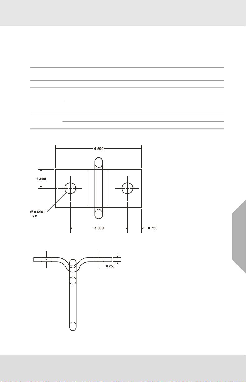
2.1 D-Plate Anchorage Connector Assembly with Mounting Plate Components
Fig. 1 Plate
Weight
US
Fig. 2 D-ring
MSA D-Plate™ Anchorage Connector Assembly
8
Page 9
Description
Fig. 3 Labels
2.1.1 D-Ring
The MSA D-ring is a connection element that is compatible with MSA snaphooks and carabiners.
The D-ring is attached to the anchorage beam or girder by use of the mounting plate. When installed
the D-ring will swivel freely in one axis to accommodate user movements.
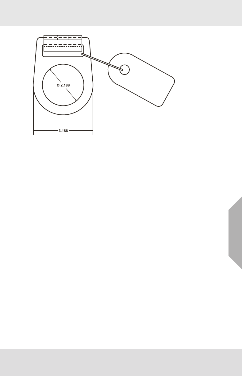
2.1.2 D-Plate
The D-Plate is a steel plate that is formed to accept the MSA D-ring and has been drilled to allow the
user to install the plate and D-ring to a pre-drilled beam or girder with user-supplied fasteners. Refer
to section 3.3.3 for a list of user-supplied fasteners required for installation.
2.1.3 Mounting Plate
The Mounting Plate is steel or aluminum designed to attach to the D-Plate to a predrilled wall or
column. Refer to section 3.3.3 "User Supplied Fasteners" for a list of user-supplied fasteners required
for installation.
MSA D-Plate™ Anchorage Connector Assembly
US
9
Page 10
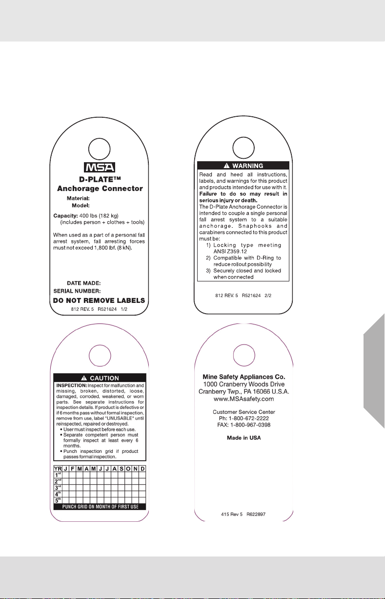
2.2 Markings and Labels
The following labels must be present, legible and securely attached to the D-Plate Anchorage
Connector Assembly. The formal inspection grid must be punched with a date (month/year) within the
last six months. If not, remove the D-Plate Anchorage Connector Assembly from use and mark it as
"UNUSABLE" until a Formal Inspection is performed in accordance with section 5.6. See section 2.1
for location of labels.
Description
MSA D-Plate™ Anchorage Connector Assembly
US
10
Page 11

2.3 System Requirements
The D-Plate Anchorage Connector Assembly is one component of multi-component systems. Without
the other necessary components, the D-Plate Anchorage Connector Assembly serves no useful
purpose. There are several different types of systems for use at heights and in confined spaces.
2.3.1 System Types
Systems are classified according to their intended purposes. There are six classifications of systems
which may be used individually or in combinations. The six basic systems classifications are:
Fall Arrest Personnel-riding Evacuation
Climbing protection Restraint Rescue
2.3.2 Fall Arrest Systems
A fall arrest system is an assembly of components and subsystems, including the necessary connectors, used to arrest the user in a fall from a working height and suspend the user until rescue can be
effected. A fall arrest system must always include a harness and connecting means between the
harness and an anchorage or anchorage connector. Such connecting means may consist of a lanyard,
energy (shock) absorber, fall arrester (rope grab), lifeline, self-retracting lanyard or suitable combinations of these.
Lanyard Connecting Subsystem is the term applied to an assembly, including the necessary connectors, which is comprised of a lanyard and a shock absorber. The lanyard and shock absorber are
usually permanently coupled together along with self-locking snaphooks at each end. The subsystem
is attached between the fall arrest attachment (back D-ring) of the harness and an anchorage or
anchorage connector. The MSA D-Plate Anchorage Connector Assembly identified in section 2 are
compatible for use with fall arrest lanyard connecting subsystems equipped with locking snaphooks up
to 0.75 in (20 mm) gate opening size.
Fall Arrester Connecting Subsystem is the term applied to an assembly, including the necessary
connectors, which is comprised of a fall arrester (rope grab) and a vertical lifeline. Sometimes a lanyard
or lanyard with integral shock absorber, including the necessary connectors, is connected to the rope
grab. The vertical lifeline must have a lifeline tensioner (counterweight), a connector for anchoring it,
and may have a shock absorber. The subsystem is attached between the fall arrest attachment (back
D-ring) of the harness and an anchorage or anchorage connector. Fall arrester connecting subsystems
are sometimes suitable for use in climbing protection systems. See section 2.3.3. MSA D-Plate
Anchorage Connector Assembly identified in section 2 are suitable for use in fall arrester connecting
subsystems.
Self-Retracting Lanyard Connecting Subsystem is the term applied to an assembly, including the
necessary connectors, comprised of a self-retracting lanyard only or a self-retracting lanyard and
added shock absorber at the point of attachment to the user’s harness. The subsystem is attached
between the fall arrest attachment (back D-ring) of the harness and an anchorage or anchorage
connector. These subsystems are sometimes suitable for use in climbing protection systems. See
section 2.3.3. The MSA D-Plate Anchorage Connector Assembly identified in section 2 are suitable for
use with self-retracting lanyard connecting subsystems.
Description
US
MSA D-Plate™ Anchorage Connector Assembly
11
Page 12

Description
Anchorage Connector
Fig. 4 Lanyard Connecting Subsystem
2.3.3 Climbing Protection Systems
A climbing protection system is an assembly of components and subsystems, including the necessary
connectors, used to arrest the user in a fall from a working height and suspend the user until rescue
can be effected. Such systems are used for climbing ladders and structures that are designed for
climbing. They may either be temporary (portable) or permanent. Temporary climbing protection
systems are described in section 2.3.2. Permanent climbing protection systems are ones of the rigid
rail type such as the MSA Dyna-Glide
to the structure to be climbed. A fall arrester device is attached to and glides on the rail to permit ascent
and descent. It quickly locks in case of a fall. The Dyna-Glide fall arrester is attached between the front
attachment (chest D-ring) of a MSA Pullover harness and the fall arrester by use of a carabiner.
Contact MSA for more information about Dyna-Glide climbing protection systems. The MSA D-Plate
Anchorage Connector Assembly identified in section 2 are suitable for use in temporary climbing
protection systems.
MSA D-Plate™ Anchorage Connector Assembly
TM
systems. In those systems, a rigid rail is permanently attached
US
12
Page 13

Description
2.3.4 Restraint Systems
A restraint system is an assembly of components and subsystems, including the necessary connectors, used to:
(a) stabilize and partially support the user at an elevated work location and allow free use of both
hands. This type of restraint system is referred to as a work positioning system or, simply, a positioning
system.
(b) restrict the user’s motion so as to prevent reaching a location where a fall hazard exists. This type
of system is referred to as a travel restriction system.
A positioning system includes a harness and connecting means between the harness and an
anchorage or anchorage connector. Such connecting means usually consists of a positioning lanyard
which is connected to both hip D-rings and wraps around or connects to an anchorage or anchorage
connector. A positioning system must always be backed up by a fall arrest system. A travel restriction
system consists of a harness and a fixed-length or adjustable-length lanyard connected between any
one of the harness D-rings and an anchorage or anchorage connector. The MSA D-Plate Anchorage
Connector Assembly described by these instructions are suitable for use in restraint systems.
2.3.5 Personnel-Riding Systems
A personnel-riding system is an assembly of components and subsystems, including the necessary
connectors, used for lifting and lowering a worker to and from a work station which is not accessible by
other preferred means, and potentially for positioning the worker while at that work station. Personnelriding systems are of two general types, namely: (a) the mobile supported aerial platform type (e.g.
manually- and self-propelled platforms and vehicle-mounted platforms), and (b) suspended personnel
hoisting type (e.g. suspended scaffolds, suspension seats, and suspension harnesses). A harness
must be used in both of these different systems; however, the way it is used will differ. When working
on mobile supported aerial platforms, the user should use a restraint system (see section 2.3.4)
anchored to the platform to provide restraint against falling from the platform. When working with the
suspended personnel hoisting type of system, the user must employ a fall arrest system of either the
self-retracting lanyard type or the fall arrester (rope grab) type. It is permissible to use a harness as a
suspension harness for making access to the work station if the access time is of very short duration
and the use of a suspension seat is not possible. The MSA D-Plate Anchorage Connector Assembly
identified in section 2 are suitable for use in personnel-riding systems. Do not use a harness for fully
suspended work positioning. Contact MSA for separate instructions on the associated equipment used
in personnel-riding systems.
2.3.6 Rescue Systems
A rescue system is an assembly of components and subsystems, including the necessary connectors,
used for moving an incapacitated or isolated person from a hazardous place to a safe place under alert
or emergency conditions. An isolated person is one who has no available means of access to a safe
place or is physically stranded or trapped. Rescue systems require actions of specially trained rescuers
to effect the rescue of the incapacitated or isolated person. When rescuing a person who is wearing a
harness, it is generally best to connect the rescue line to the chest D-ring. Alternatively, it is acceptable
(but less desirable) to connect the rescue line to both of the shoulder D-rings using a “Y” retrieval
lanyard. If the harness being used by the person being rescued has neither a chest D-ring nor shoulder
D-rings, the back D-ring may be used as a last resort to connect the rescue line. MSA strongly recommends that the user select a harness with a chest D-ring to provide for rescue. The MSA D-Plate
Anchorage Connector Assembly identified in section 2 may be used in certain rescue applications.
2.3.7 Evacuation Systems
An evacuation system is an assembly of components and subsystems, including the necessary
connectors, employed by the user to move, unassisted by others, from a hazardous place to a safe
place under alert or emergency conditions. An evacuation system consists of a harness and
connecting means between the harness and an anchorage or anchorage connector. See the separate
instructions for this equipment. The MSA D-Plate Anchorage Connector Assembly identified in
section 2 are suitable for use in evacuation systems.
US
MSA D-Plate™ Anchorage Connector Assembly
13
Page 14

2.3.8 Combinations of Systems
Systems for fall arrest, restraint, climbing protection, personnel-riding, rescue and evacuation are often
used in combination. For example, positioning type restraint systems must be backed up by a separate
and independent fall arrest system. Hands-on training is required to obtain the necessary information
and skills needed to work with combinations of systems. Refer to the separate instructions accompanying the several components and subsystems necessary to make up these systems.
2.4 Compatibility of System Parts
2.4.1 Compatibility of Components and Subsystems
MSA D-Plate Anchorage Connector Assembly are designed to be used with MSA approved components and connecting subsystems. Use of the D-Plate Anchorage Connector Assembly with products
made by others that are not approved in writing by MSA may adversely affect the functional compatibility between system parts and the safety and reliability of the complete system. Connecting subsystems must be suitable for use in the application (e.g. fall arrest, climbing protection, restraint, rescue
or evacuation). MSA produces a complete line of connecting subsystems for each application. Contact
MSA for further information. Refer to the manufacturer’s instructions supplied with the component or
connecting subsystem to determine suitability. For fall arrest applications using MSA D-Plate
Anchorage Connector Assembly, the maximum fall arrest force must not exceed 1,800 lbf (8 kN).
Contact MSA with any questions regarding compatibility of equipment used with the MSA D-Plate
Anchorage Connector Assembly.
2.4.2 Compatibility of Connectors
Connectors, such as D-rings, snaphooks, and carabiners, must be rated at 5,000 lbf (22 kN) minimum
breaking strength. MSA connectors meet this requirement. Connecting hardware must be compatible
in size, shape, and strength. Non-compatible connectors may accidentally disengage ("rollout").
Always verify that the connecting snaphook or carabiner and the D-ring on the harness or anchorage
connector are compatible. Use only self-closing, self-locking snaphooks and carabiners (as defined
and required by ANSI Z359.12).
2.4.3 Anchorages and Anchorage Connectors
Anchorages for personal fall arrest systems must either: (a) have a strength capable of supporting and
withstanding at least 5,000 pounds (22.2 kN) in the directions permitted by the system without failure,
or (b), must be certified by a professional engineer as having the required strength for fall arrest or
travel restraint, as applicable. See ANSI Z359.18 for definition of certification. When more than one
personal fall arrest system is attached to an anchorage, the anchorage strengths set forth in (a) and
(b) must be multiplied by the number of systems attached to the anchorage. This requirement is consistent with OSHA requirements under 20 CFR 1910, Subpart F, Section 1910.66, Appendix C.
Do not proceed with installation and use of the anchorage connector if an assessment of strength
cannot be made.
Description
US
MSA D-Plate™ Anchorage Connector Assembly
14
Page 15

3 Use
3.1 Planning the Use of Systems
Perform the hazard identification and evaluation described in section 1.4.6 of these instructions. Then
plan the system(s) before starting work. Consider all possible paths of user movement and all factors
that could affect the user’s safety before, during, and after a fall anywhere along these paths. A qualified person must select the components, materials, anchorage and anchorage connectors to match
the system application, the work, workplace hazards, and the environment. Consider the following
points when planning the system(s).
3.1.1 Anchorage and Anchorage Connector Selection
Determine the necessary locations of anchorages to assure that the user will be continuously
connected when exposed to hazards of falling. Select anchorages that are stable and have the
strength required by section 2.4.3 of these instructions. Carefully select the locations of the anchorages to: (a) reduce possible free fall distance, (b) prevent swing fall hazards, and (c) provide clear
space in the potential fall paths to avoid striking an object. Do not select anchorage locations that will
require the user to work above them as this will increase the potential free fall and total fall distances.
Plan the types of anchorage connectors that will need to be selected and refer to these instructions.
Use
MSA D-Plate™ Anchorage Connector Assembly
US
15
Page 16

Free Fall Distance
WARNING!
DO NOT climb above anchorage.
Failure to follow this warning can result in serious personal injury or death.
BEFORE FALL
Lanyard
Use
Working Surface
Deceleration
(shock absorber
activation)
FREE FALL
SUSPENSION
AFTER FALL
ARREST
Clearance
Fig. 5 Free Fall Distance
(1) Free fall distance.
(2) Total fall distance. The sum of the free fall distance and deceleration distance.
(3) Deceleration distance. Must not exceed 3.5 ft (1.1 m).
MSA D-Plate™ Anchorage Connector Assembly
Closest Object in Fall Path
US
16
Page 17

Swing Fall Hazard
WARNING!
Prevent swing falls and impact with object in or adjacent to the fall path. Work directly under the
anchorage/anchorage connector at all times.
Failure to follow this warning can result in serious personal injury or death.
Anchorages
Use
Incorrect
Fig. 6 Swing Fall Hazard
Correct
3.1.2 Free Fall Distance, total Fall Distance, and System Elongation
See separate instructions for connecting subsystems to determine allowable free fall, as well as the
deceleration distance and dynamic elongation which must be allowed for in the space of potential fall
paths. Total fall distance is the sum of free fall distance and deceleration distance. Dynamic elongation
of the system (temporary elastic stretch of connecting components and subsystems) must be added
to total fall distance and clearance allowed.
3.1.3 User Movements
Identify all necessary movements of the user and the materials and equipment needed to perform the
planned work. Plan for avoidance of the crossing or tangling of connecting subsystems of two or more
workers. Anticipate user movements that might introduce hazards of the connecting subsystem
passing under, about or between body parts or invite the user to clamp, knot or otherwise prevent the
connecting subsystem from functioning properly. Establish controls to prevent these occurrences.
3.1.4 Pendulum (swing) Falls
Swing falls can occur when the system is not anchored directly above the user. The force of striking an
object in a pendular motion can cause serious injury. Always minimize swing falls by working as directly
below the anchorage point as possible.
MSA D-Plate™ Anchorage Connector Assembly
US
17
Page 18

Use
3.1.5 Anchorage Loading
The specific application will determine potential directions of loading. Perform a workplace assessment
in accordance with section 1.4.6 and limit exposure to swing falls in accordance with section 3.1.4 to
avoid side loading situations.
WARNING!
The D-Plate Anchorage Connector Assembly is not suited for supporting side loads. Installation must
be planned so that potential fall arrest loads are applied vertically and directly below the anchorage
connector.
Failure to follow this warning can result in serious personal injury or death.
Correct
Fig. 7 Loading direction
Fall Arrest
In fall arrest applications, the D-Plate Anchorage Connector Assembly should be mounted to the
underside of a horizontal beam or girder with the D-ring hanging straight down when properly assembled to the anchorage. In this position the D-ring is free to swing from side to side about the long axis
of the D-ring slot. Care should be taken to mount the D-Plate Anchorage Connector Assembly so that
user movement does not cause loading other than straight down from the point of attachment.
Restraint
In restraint applications, the D-Plate Anchorage Connector Assembly may be mounted on a vertical
surface such as a vertical column of sufficient strength as defined in section 3.1.1.
Incorrect
US
MSA D-Plate™ Anchorage Connector Assembly
18
Page 19

3.1.6 Clear Space in Fall Path
Make certain that enough clearance is available in all potential fall paths to prevent striking an object.
The amount of clearance needed depends upon the type of connecting subsystem used, and the location of the anchorage. Consult the manufacturer’s instructions for the particular connecting subsystem
or component for clearance needed.
3.1.7 Hazards Identified in Workplace Assessment
All hazards of the type set forth in section 1.4.6 of these instructions must be addressed and suitable
controls planned and implemented. For example, if work must be performed near unavoidable sharp
edges, plan to protect against cutting by use of heavy padding or other means of covering the sharp
edge.
3.1.8 Rescue and Evacuation
The user must have a rescue plan and the means at hand to implement it. The plan must take into
account the equipment and special training necessary to effect prompt rescue under all foreseeable
conditions. If the rescue be from a confined space, the provisions of OSHA regulation 1910.146 and
ANSI Z117.1 must be taken into account. Although a rescue plan and the means to implement it must
always be in place, it is a good idea to provide means for evacuation without assistance of others. This
will usually reduce the time to get to a safe place and reduce or prevent the risk to rescuers.
3.2 D-Plate Anchorage Connector Assembly Inspection Before Each Use
Inspect the D-Plate Anchorage Connector Assembly to verify that it is in serviceable condition. See
section 5 for inspection details. Do not use D-Plate Anchorage Connector Assembly if inspection
reveals an unsafe condition.
3.3 Installation of the D-Plate Anchorage Connector Assembly
3.3.1 Anchorage Preparation
Begin by preparing the anchorage (e.g. beam, girder, etc.). The anchorage should be clean and dry
before installing the D-Plate Anchorage Connector Assembly. Holes must be drilled into the flange of
the anchorage that match the pattern of the D-plate or mounting plate and the diameter of the mounting
plate holes and the size of the user-supplied bolts. See sections 1.4.6 and 3.1 for considerations in
locating the anchorage connectors for the work to be performed. See section 2.1 for the mounting plate
hole pattern.
Use
MSA D-Plate™ Anchorage Connector Assembly
US
19
Page 20

3.3.2 Installation Diagram
8
5
6
7
3
2
4
1
2
4
3
1
6
5
9
WARNING!
When installing or removing the D-Plate Anchorage Connector Assembly, limit exposure to fall
hazards. A separate independent fall arrest system may be required.
Failure to follow this warning can result in serious personal injury or death.
Use
US
Fig. 8 S-beam Installation
1 D-Plate 6 Flat Washer (4)
2 D-Ring 7 Tampered Washer
3 Bolt 8 S-beam Anchorage
4 Labels (2) 9 W-beam Anchorage
5 Lock Nut
MSA D-Plate™ Anchorage Connector Assembly
20
Page 21

Use
3.3.3 User Supplied Fasteners
The user must select and obtain the appropriate fasteners to attach the D-Plate Anchorage Connector
Assembly. Refer to the illustrations in section 3.3.2.
For W-beams For S-beams
Two (2) Grade-5 bolts, 0.5 in (13 mm) diameter, of
length sufficient to reach through the plate, beam
flange and lock washer.
Four (4) SAE-type flat washers, 0.5 in (13 mm)
nominal inside diameter.
Two (2) lock nuts, 0.5 in (13 mm) with threads to
match the Grade-5 bolts.
3.3.4 Installation Sequence
(1) Hold the mounting plate (when provided) and D-ring assembly in position and aligned to the pre-
drilled holes in the vertical anchorage.
(2) Assemble a bolt up through the D-plate, mounting plate (when provided), flange, angle washer
(when needed for S-beam installations), lock washer and nut. Hand tighten the nut onto the bolt.
Repeat this process for the other bolt. Be sure there is a bolt, washers and nut for every hole in
the mounting plate.
(3) Tighten each nut to 7 ft lb (9 Nm) torque.
(4) Inspect the installation. Verify that all components are present and correctly mounted. The D-ring
must move freely on the mounting plate.
WARNING!
DO NOT leave the MSA D-Plate Anchorage Connector Assembly installed in environments which
could cause damage or deterioration to the product. Refer to sections 4 "Cleaning, Maintenance
and Storage" and 5 "Inspection" for care and inspection details.
DO NOT leave unattended loads on the D-Plate Anchorage Connector Assembly.
DO NOT use on cinder block walls
DO NOT use unless a qualified person has designed and inspected the system.
Failure to follow these warnings may result in serious injury or death.
Two (2) Grade-5 bolts, 0.5 in (13 mm) diameter, of
length sufficient to reach through the plate, beam
flange, tapered washer and lock washer.
Two (2) tapered (angle) washers, 0.5 in (13 mm)
nominal inside diameter.
Four (4) SAE-type flat washers, 0.5 in (13 mm)
nominal inside diameter.
Two (2) lock nuts, 0.5 in (13 mm) with threads to
match the Grade-5 bolts.
US
3.3.5 Installation of Mounting Plate to Concrete
MSA requires that the mounting plate be attached to 3,000 psi (20.7 MPa) solid concrete, to a minimum
depth of 4.5 inches, at least 6 inches from any edge using the Hilti product described below. Users
must follow installation instructions provided by Hilti.
Approved anchors: Hilti HY-150 injection adhesive anchor including:
• 1/2 inch diameter x 6.5 inch long stainless steel (SST) ANSI 316 anchor rods
• 1/2 inch SST nuts, washers, and lock washers
Inspect the installation to verify each bolt is in the correct position and properly tightened, and verify
the mounting plate is fully seated before continuing onto operation of the system.
MSA D-Plate™ Anchorage Connector Assembly
21
Page 22

Care, Maintenance and Storage
3.4 Making Connections
When using a snaphook or carabiner to connect to an anchorage or when coupling components of the
system together, be certain accidental disengagement ("rollout") cannot occur. Rollout is possible
when interference between a carabiner and the mating connector causes the carabiner's gate or
keeper to accidentally open and release. Rollout occurs when a carabiner is snapped into an undersized ring such as an eye bolt or other non-compatibly shaped connector. Only self closing, self-locking
snaphooks and carabiners should be used to reduce the possibility of rollout when making connections. Do not use snaphooks or connectors that will not completely close over the attachment object.
Do not make knots in a lanyard. Do not hook a lanyard back onto itself. Snaphooks and carabiners
must not be connected to each other. Do not attach two snaphooks or carabiners into one D-ring.
Do not attach snaphooks or carabiners directly to a horizontal lifeline. Always follow the manufacturer’s
instructions supplied with each system component.
3.5 Removal of the D-Plate Anchorage Connector Assembly
Before attempting removal of the D-Plate Anchorage Connector Assembly, disconnect all loads and
attachment elements from the Anchorage Connector D-ring. Return the D-Plate Anchorage Connector
Assembly to the appropriate person in the user's organization for cleaning, inspection and storage.
4 Care, Maintenance and Storage
4.1 Cleaning Instructions
Clean the D-Plate Anchorage Connector Assembly with a solution of water and mild laundry detergent.
Dry hardware with a clean cloth and hang to air dry. Do not speed dry with heat. Excessive accumulation of dirt, paint or other foreign matter may prevent proper function of the D-Plate Anchorage
Connector Assembly. Questions concerning D-Plate Anchorage Connector Assembly conditions and
cleaning should be directed to MSA.
4.2 Maintenance and Service
Equipment which is damaged or in need of scheduled maintenance must be tagged as “UNUSABLE”
and removed from service. Corrective maintenance (other than cleaning) and repair, such as replacement of elements, must be performed by MSA. Do not attempt repairs.
4.3 Storage
Store the D-Plate Anchorage Connector Assembly in a cool, dry and clean place out of direct sunlight.
Avoid areas where heat, moisture, light, oil, and chemicals or their vapors or other degrading elements
may be present. Equipment which is damaged or in need of scheduled maintenance should not be
stored in the same area as usable equipment. Heavily soiled, wet, or otherwise contaminated equipment should be properly maintained (e.g. dried and cleaned) prior to storage. Prior to using equipment
which has been stored for long periods of time, a Formal Inspection should be performed by a competent person.
US
MSA D-Plate™ Anchorage Connector Assembly
22
Page 23

5 Inspection
5.1 Inspection Frequency
The D-Plate Anchorage Connector Assembly must be inspected by the user before each use and,
additionally, by a competent person other than the user at intervals of no more than six months.
The competent person inspection is referred to as Formal Inspection. See section 5.6 for Formal
Inspection procedures.
The program administrator shall maintain documentation of equipment inspections. This documentation shall include, at a minimum, the identify of the equipment, inspection date, name of the competent
or qualified person conducting the inspection and the result of that inspection.
The program administrator shall set inspection criteria for the equipment. Such criteria shall equal or
exceed the most restrictive of the criteria established by the ANSI Z359.18 standard or the manufacturer’s user instructions. Keep inspection criteria current in relationship to changing patterns or conditions of use.
5.2 Procedure for Inspection
(1) Inspect the D-Plate Anchorage Connector Assembly labels to verify that they are present and
legible. See section 2.1 for location of labels for each model. See section 2.2 for the specific
labels that should be present and the information contained on those for the model number
shown on page one (1) of these instructions. Check the Formal Inspection Grid to be sure a
Formal Inspection has been performed within the last six months. If the Grid does not indicate
that a Formal Inspection has been performed within the last six months (by being punched), or
if any labels are missing or illegible, remove the D-Plate Anchorage Connector Assembly from
use and mark it as "UNUSABLE" until a Formal Inspection is performed by a competent person.
(2) Inspect the D-ring, D-plate, Mounting Plate and user supplied fasteners (bolts, washers,
angle washers, and nuts) for deformation, damage, fractures, cracks, corrosion, deep pitting,
sharp edges, cuts, deep nicks, evidence of excessive heat or chemical exposures and inadequate maintenance of equipment, alteration, excessive wear, or any condition that calls to question the suitability of the equipment for its intended purpose.
(3) Inspect the anchorage wall or column for evidence of cracking, fracturing, breakdown of
concrete structure.
(4) Inspect the plastic labels for their presence and legibility.
(5) Inspect each component and subsystem of the complete system in accordance with the associ-
ated manufacturer's instructions. See section 2.3 for a description of the make-up of the different
types of subsystems and systems.
5.3 Corrective Action
When inspection in accordance with section 5 "Inspection" reveals any of the identified conditions, the
MSA D-Plate Anchorage Connector Assembly must be immediately removed from service and marked
as "UNUSABLE" until destroyed or subjected to corrective maintenance by the user's organization in
accordance with this user instruction. Damage, excessive wear, malfunction, and aging are generally
not repairable. If detected, immediately remove the D-Plate Anchorage Connector Assembly from use
and mark it as "UNUSABLE' until destroyed. For final disposition, submit the Bolt D-Ring Anchorage
Connector to a competent person who is authorized to perform Formal Inspection. If there is any question as to repairability, contact MSA or a service center authorized in writing by MSA before further use
of the product.
Inspection
US
WARNING!
Unauthorized alterations, relocations, or additions to the anchorage connector are not permitted.
MSA or persons or entities authorized in writing by the manufacturer, shall make all repairs to the
equipment. No unauthorized repairs and/or modifications are permitted.
Failure to follow these warning can result in serious personal injury or death.
MSA D-Plate™ Anchorage Connector Assembly
23
Page 24

5.4 Formal Inspection Frequency
The D-Plate Anchorage Connector Assembly must be formally inspected by a competent person other
than the user at intervals of no more than six months. (The qualifications of a competent person are
established by OSHA.) If the product is exposed to severe working conditions, more frequent formal
inspections may be required. The frequency of inspection by a competent person should be established by the user’s organization based on such factors as the nature and severity of workplace conditions, modes of use, and exposure time of the equipment. The competent person should perform a
methodical and thorough visual and tactile inspection by following the inspection procedure in
section 5.6. The inspection results should be recorded in the Formal Inspection Log and retained for
reference. In addition, if the D-Plate Anchorage Connector Assembly passes Formal Inspection, the
competent person, using a ballpoint pen, should punch the date (month and year) of Formal Inspection
on the grid supplied with the labels on each product. The user should never punch this grid; however,
the user should check it before each use to be sure a Formal Inspection has been performed within
the last six months.
5.5 Control of Equipment
The user’s organization should establish and enforce a policy and procedure whereby any D-Plate
Anchorage Connector Assembly that is found to be defective, damaged, or in need of maintenance be
immediately removed from use, marked as “UNUSABLE” and immediately thereafter submitted to
custody of the competent person responsible for Formal Inspection.
This has the benefits that:
1) defective equipment is secured from further use until proper action is taken;
2) uniform standards are applied for determining whether the equipment is acceptable or not acceptable for further use;
3) uniform methods of cleaning and other maintenance are applied; and
4) there is a central point for evaluation of conditions that may be recurring and require preventive
measures such as coordination with the equipment manufacturer, selection of alternate equipment, additional training of equipment users, or changes to the workplace conditions.
Inspection
MSA D-Plate™ Anchorage Connector Assembly
US
24
Page 25

5.6 Formal Inspection Procedure
The Formal Inspection Procedure is similar to the user’s inspection before each use described in
section 5. However, it differs in three important respects, namely:
1) it is performed by a competent person other than the user who is trained and authorized to perform
Formal Inspection for the user’s organization;
2) it is more detailed and is methodically recorded on a Formal Inspection Log that is kept on file for
future reference; and
3) it results in final disposition of the equipment as either “acceptable” or as “not acceptable” followed
by destruction of the product.
There are three forms that are important to the Formal Inspection Procedure. They are the
Formal Inspection Diagram ("DIAGRAM"), the Formal Inspection Log ("LOG"), and the Formal Inspection Checklist and Codes ("CHECKLIST"). These forms relate and refer to each other so it is necessary
to understand their purposes and uses before discussing the inspection procedure.
5.6.1 Diagram
This is a set of line drawings of the D-Plate Anchorage Connector Assembly. Each has numbered callouts of the parts. The numbers called out in the DIAGRAM correspond to those shown on the column
titled "INSP. POINT" (inspection point) on the LOG.
5.6.2 Log
This is the form to be used to record observations made during the Formal Inspection. The Model No.,
Serial No. and Date Made are recorded by the inspector from the label set. The formal inspector’s
name and the inspection date are entered by the inspector. The "Disposition" entry is the last entry
made on this form after all observations have been recorded. The entry is either "Acceptable" ("PASS")
or "Not Acceptable" ("FAIL"). The columns on the LOG are as follows:
• Insp. Point - Inspection point. The D-Plate Anchorage Connector Assembly part designated in the
callouts on the DIAGRAM.
• Description - Name of the D-Plate Anchorage Connector Assembly inspection point.
• QTY/DP - Quantity per D-Plate Anchorage Connector Assembly. The quantity of each D-Plate
Anchorage Connector Assembly inspection point that must be inspected.
• Cond. - Condition. The condition of the D-Plate Anchorage Connector Assembly part is indicated
here by entry of the appropriate Condition Code shown on the CHECKLIST (e.g. M0, P2, etc.).
Alternatively, the inspector may simply enter "FAIL" if a defective condition exists and make no
entry if no defect exists.
• Overall Assess. - Overall assessment. The inspector’s evaluation of the overall acceptability or
non-acceptability of the part category (e.g. webbing, stitching, metallic, plastic). The appropriate
Overall Assessment Code defined on the CHECKLIST is entered here (e.g. MA, PN, etc.). Alternatively, the inspector may simply enter "FAIL" if a defective condition exists and make no entry if
no defect exists.
• Comments - Indicate pertinent inspector observations here.
5.6.3 Checklist and Codes
This is a table which categorizes the different types of D-Plate Anchorage Connector Assembly parts.
For each of these categories that are applicable to a specific product, the formal inspector checks the
D-Plate Anchorage Connector Assembly parts for each of the associated conditions (e.g. deformation,
corrosion, etc.). The codes for the detected conditions are entered in the Condition column on the LOG
(e.g. M1, P0, etc.). Overall assessment codes are given, along with the criteria for assigning them, so
the inspector can decide if the D-Plate Anchorage Connector Assembly is acceptable or not acceptable
for further use (e.g. MA, MN, PA, PN). Alternatively, instead of using these codes, the inspector may
simply enter "FAIL" if a defective condition exists and make no entry if no defect exists.
Inspection
US
MSA D-Plate™ Anchorage Connector Assembly
25
Page 26

Inspection
5.6.4 Formal Inspection Procedural Steps
(1) Record on the LOG the Model No., Serial No. and Date Made information shown on the product
label set. Record the inspector’s name and inspection date.
(2) Arrange the D-Plate Anchorage Connector Assembly so the parts to be inspected are readily
visible.
(3) Starting with the parts shown on the LOG, inspect each part (inspection point) one at a time.
Refer to the DIAGRAM for identification of each inspection point. Each part must be inspected
for the possible presence of the conditions shown on the CHECKLIST. Enter in the Condition
column on the LOG the proper Condition Code (listed on the CHECKLIST) or "FAIL" if a defect
exists. If there is any question whether the product condition has materially changed since the
last Formal Inspection, retrieve and review the prior Formal Inspection records for the specific
product.
(4) Determine whether the part (inspection point) is acceptable or not acceptable. If an inspection
point has a defective condition, enter in the Overall Assessment column of the LOG the proper
code taken from the CHECKLIST or simply "FAIL."
(5) Determine disposition of the D-Plate Anchorage Connector Assembly. If in step 4 it has been
determined that the D-Plate Anchorage Connector Assembly is not acceptable, enter "N" or
"FAIL" in the Disposition space on the LOG. In addition, a notation should be made in this space
as to whether the D-Plate Anchorage Connector Assembly is to be destroyed, returned to manufacturer/distributor, etc.
(6) If in step 4 it has been determined that the D-Plate Anchorage Connector Assembly is accept-
able for further use, enter "A" or "PASS" in the Disposition space on the LOG.
(7) File the LOG for future reference.
MSA D-Plate™ Anchorage Connector Assembly
US
26
Page 27

5.7 Formal Inspection Checklist and Codes
Inspection
Type of
Part
Inspected
Metallic
Structure
Plastic
Condition
Deformed/fractured M1
Corroded/deep pits M2
Missing/loose M3
Heat exposure M4
Chemical exposure M5
Burrs/sharp edges M6
Cuts/deep nicks M7
Malfunction M8
Other M9
No visible change M0
Chips S1
Cracks/fracture S2
Missing/Loose S3
Burns/heat exposure S4
No visible change S0
Cut/broken/deformed P1
Wear damage P2
Missing/loose P3
Burns/heat exposure P4
Chemical Exposure P5
Other P6
No visible change P0
Cond.
Code
Overall Assessment Code
MA - (Metallic acceptable)
MN - (Metallic not acceptable)
SA - (Structure acceptable)
SN - (Structure not acceptable)
PA - (Plastic acceptable)
PN - (Plastic not acceptable)
Legend
Disposition:
A - (Acceptable) N - (Not acceptable)
Enter "A" (or "PASS") or "N" (or "FAIL") in Disposition blank on Formal Inspection Log.
Criteria for disposition of "N" (Not acceptable):
If there is one or more Overall Assessment Code of "N" type (e.g. WN, SN, MN, PN).
MSA D-Plate™ Anchorage Connector Assembly
US
27
Page 28

5.8 Inspection Log
Example:
Model No.: 506632 Inspector: J.W.Doe
Serial No.: 12345
Date Made: 1/12 Disposition:
Inspection
Date:
Inspection
6/4/12
N - See item 1, Destroy D-Plate Anchorage
Connector Assembly.
INSP.
DESCRIPTION QTY/DP
POINT
METALLIC PARTS
1 D-ring 1 M1 MN
2 D-Plate 1 M0 MA
3 Mounting Plate 1 M0 MA
4 Anchor-Screw (user supplied) 4 M0 MA
Flat Head Screws (user
5
supplied)
6 Nut 6 M0 MA
7 Washer 6 M0 MA
STRUCTURED PARTS
8 Anchorage Structure NA S0 SA
PLASTIC PARTS
9 Labels 2 P0 PA
2 M0 MA
COND
. (a)
OVERALL
ASSESS. (a)
COMMENTS
D-ring is elongated,
has experienced load
US
MSA D-Plate™ Anchorage Connector Assembly
28
Page 29

Blank
Model No.: Inspector:
Serial No.:
Inspection
Date:
Date Made: Disposition:
Inspection
INSP.
DESCRIPTION QTY/DP
POINT
COND.
(a)
OVERALL
ASSESS. (a)
COMMENTS
METALLIC PARTS
1 D-ring 1
2 D-Plate 1
3 Mounting Plate 1
4 Anchor-Screw (user supplied) 4
Flat Head Screws
5
(user supplied)
2
6 Nut 6
7 Washer 6 M0 MA
STRUCTURED PARTS
8 Anchorage Structure NA S0 SA
PLASTIC PARTS
9 Labels 2 P0 PA
(a)
Optional simplified PASS/FAIL inspection format: Whenever an acceptable condition is found, the entry in the
COND. and OVERALL ASSESS. columns may be left blank. Whenever a defective condition is found, enter "FAIL."
The inspection may end upon detection of a single defective condition.
Blank copies of this LOG, with associated CHECKLIST and DIAGRAM, are available from MSA.
(b)
Call Toll Free 1-800-672-2222.
US
MSA D-Plate™ Anchorage Connector Assembly
29
Page 30

US
MSA D-Plate™ Anchorage Connector Assembly
30
Page 31

US
MSA D-Plate™ Anchorage Connector Assembly
31
Page 32

For local MSA contacts, please visit us at MSAsafety.com
 Loading...