

Page 1
Locate the detector:
• indoors in a room area where air circulates freely
• indoors in an area near fittings where refrigerant leaks may occur
• on a flat, interior surface
• approximately 12-18 inches (30-45 cm) from floor
Do not locate the detector:
• near heat sources, such as appliances, direct sunlight or concealed pipes or chimneys
• on walls or structures subject to excessive vibration
• in areas where air does not circulate freely, such as behind doors or in corners.
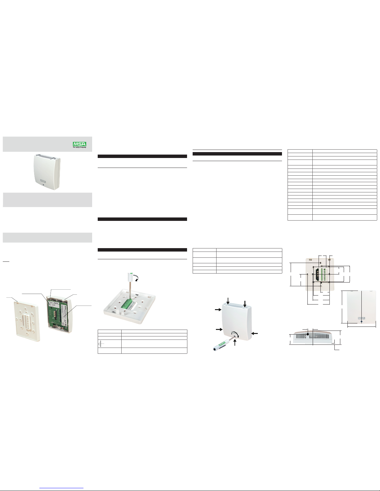
3.2 Mounting the detector
The detector consists of two basic parts, the base and the cover (Figure 1). The cover
incorporates the electronics with the sensing elements.
1. Fasten the base to a junction box or other support.
• The base has a number of openings to allow for mounting to various junction boxes.
CONFIGURATION LABEL
TOP
APPROVAL LABEL
BASE
SERIAL NUMBER LABEL
Figure 1: Base and Cover
2. Feed the power and signal wires through the rectangular opening in the base.
1 SAFETY REGULATIONS
1.1 Correct Use
MSA’s CHILLGARD® VRF Refrigerant Detector – hereafter referred to as detector – is
designed to detect the presence of the most common halogenated refrigerants, and
specifically calibrated to detect R410a.
WARNING
This manual must be carefully read by all individuals who have or will have the responsibility for
installing, using, or servicing the product. This product is supporting life and health. Incorrect use,
maintenance, or servicing may affect the function of the device and persons who rely on this product for
their safety could sustain loss of life or serious personal injury.
Furthermore, the national regulations applicable to the user’s country must be taken into
account for safe use of this product. Alternative use, or use outside of this specification will
be considered as non-compliance. This also applies especially to unauthorized alterations to
the product and to commissioning work that has not been carried out by MSA or authorized
persons.
1.2 Liability Information
MSA accepts no liability in cases where the product has been used inappropriately or not
as intended. The selection and use of this product must be under the direction of a qualified
safety professional who has carefully evaluated the specific hazards of the site where it will
be used and who is completely familiar with the product and its limitations. The selection and
use of this product and its incorporation into the safety scheme of the site is the exclusive
responsibility of the employer.
Warranties, also known as guarantees, made by MSA with respect to the product are voided
if the product is not used, serviced, or maintained in accordance with the instructions in this
manual.
1.3 Safety and Precautionary Measures
WARNING
Carefully review the following safety limitations and precautions before placing this device in service.
Incorrect use can cause loss of life or serious personal injury.
• Install, operate, and maintain this instrument in strict accordance with its labels, cautions, warnings,
instructions, and within the limitations stated.
• Do not install this detector in outdoor areas or locations where explosive concentrations of
combustible gases or vapors might occur in the atmosphere. Do not paint this detector. Painting will
interfere with the sampling process of the detector. If painting is being done in an area where the
detector is located, exercise care to ensure that paint is not put or splashed on the detector.
WARNING
The unit must always be powered by either a suitable UL/CSA/IEC 60950 Certified power supply which is
isolated from line voltage by double insulation, or an appropriately rated UL Listed/CSA Certified Class 2
transformer. Failure to follow the above can result in serious personal injury or loss of life.
3. Connect the wires to the terminal connector located in the base, as indicated in Figure 2. The
terminal block on the base includes a label to identify the connections. Figure 3 shows the
wiring connection definitions. All units come with an analog and a digital output. The analog
output will be either current (mA) or voltage (V) and the digital output will be either BACnet
or Modbus. The choice is made based on the part number ordered.
Figure 2: Connecting Wires to Terminal Connector
Terminal Label Description
24V+ 24 V DC+ or AC Line
24V- 24 V DC- or AC Neutral
Circuit common/analog signal reference
GAS OUT
(mA or V)
For (mA) – Gas reading as current (4 - 20 mA = 0 - 1000 ppm)
For (V) – Gas reading as voltage (2 - 10 V = 0 - 1000 ppm)
• Protect this detector from vibration and heat; otherwise improper operation may result.
• Verify product operability. Do not use the detector if the function test is unsuccessful or the detector
is damaged.
• Ensure that all servicing is performed by MSA authorized technicians, using genuine MSA
replacement parts
CAUTION
Install this detector in as clean and dry area as possible and install splash shields to keep water and
other contaminants away from the detector; otherwise, damage can occur.
1.4 Warranty
1. Seller warrants that this product will be free from mechanical defect or faulty workmanship
for a period of 18 months from date of shipment, provided it is maintained and used in
accordance with Seller’s instructions and/or recommendations. This warranty does not apply
to expendable or consumable parts whose normal life expectancy is less than one (1) year
such as, but not limited to, non-rechargeable batteries, filament units, filter, lamps, fuses etc.
The Seller shall be released from all obligations under this warranty in the event repairs or
modifications are made by persons other than its own or authorized service personnel or if the
warranty claim results from physical abuse or misuse of the product. No agent, employee or
representative of the Seller has any authority to bind the Seller to any affirmation, representation
or warranty concerning the goods sold under this contract. Seller makes no warranty
concerning components or accessories not manufactured by the Seller, but, to the extent
possible, will pass on to the Purchaser all warranties of manufacturers of such components.
THIS WARRANTY IS IN LIEU OF ALL OTHER WARRANTIES, EXPRESSED, IMPLIED
OR STATUTORY, AND IS STRICTLY LIMITED TO THE TERMS HEREOF. SELLER
SPECIFICALLY DISCLAIMS ANY WARRANTY OF MERCHANT ABILITY OR OF FITNESS
FOR A PARTICULAR PURPOSE.
2. Exclusive Remedy - It is expressly agreed that Purchaser‘s sole and exclusive remedy for
breach of the above warranty, for any tortious conduct of Seller, or for any other cause of
action, shall be the repair and/or replacement at Seller‘s option, of any equipment or parts
thereof, which after examination by Seller is proven to be defective. Replacement equipment
and/or parts will be provided at no cost to Purchaser, F.O.B. Seller‘s Plant. Failure of Seller to
successfully repair any non-conforming product shall not cause the remedy established hereby
to fail of its essential purpose.
3. Exclusion of Consequential Damage - Purchaser specifically understands and agrees that
under no circumstances will seller be liable to purchaser for economic, special, incidental or
consequential damages or losses of any kind whatsoever, including but not limited to, loss of
anticipated profits and any other loss caused by reason of non-operation of the goods. This
exclusion is applicable to claims for breach of warranty, tortious conduct or any other cause
of action against seller.
4. This detector has no user-replaceable parts. Modification of the unit will void the warranty.
Terminal Label Description
DATA a
(BACnet or Modbus)
For BACnet – RS485 BACnet MSTP (a) connection
For Modbus – RS485 Modbus RTU (a) connection
DATA b
(BACnet or Modus)
For BACnet – RS485 BACnet MSTP (b) connection
For Modbus – RS485 Modbus RTU (b) connection
NO Relay – normally open (de-energized)
C Relay – common
NC Relay – normally closed (de-energized)
Figure 3: Wiring Connections
4. Align the top side tabs of the cover with the base and snap the cover onto the base, and
fasten the screw.
Note: Verify cover is securely attached to base by pulling on the top and bottom of
the cover as shown in Figure 4.
5. To remove the cover, remove the screw and pull the enclosure away from the base as show
in Figure 4.
Screw on
Grasp here and
pull to release
Snap on (2 places)
Pull on top
to verify
the attachment
Grasp here and
pull to release
Figure 4: Attaching or Removing the Cover
2 SPECIFICATIONS
This detector detects R410a with a number of output options. This includes analog output
(current or voltage) and RS-485 digital output (Modbus or BACnet). Check label provided on
the printed circuit board (Figure 1- shows the label).
Power Requirements 24 VDC ±20 %, 24 VAC ±20 %, 50/60 Hz, Class 2
Wiring 14 AWG max (up to 2.5 mm
2
), Class 2 copper wiring
Power Consumption Less than 5 watts
Output Options 4 to 20 mA sourcing, ≤500 Ohm load, 2-10 V, 10 K Ohm load,
RS-485: Modbus RTU, BACnet MS/TP
Operating Temp. 0 °C to 60 °C
Humidity 0 to 99 % non-condensing
Size 4.7” x 4.1” x 1.7” (11.9 cm x 10.4 cm x 4.3 cm)
Weight 0.51 lbs. (230 g)
Pressure Operating 10.2 to 15.7 PSIA (70 to 108 kPa)
Altitude 0-2000 m
Warm-up time 30 Minutes
Pollution Degree 2
Installation Category II
Range 0 to 1000 ppm
Minimum Detection 25 ppm
Response Time t50 less than 240 seconds
Repeatability ±10 ppm at 50 ppm
Linearity ±10 ppm from 25-50 ppm,
±20 % of reading from 50 to 1000 ppm
Relay Rated load: 1 A at 30 VDC, Max. operating current: 1 A,
Max. switching capacity: 30 W
3 INSTALLATION GUIDELINES
3.1 Locating the detector
Proper detector location is necessary to ensure accurate measurement of representative air
samples.
3.3 Dimensions in mm [inch]
26.4
[1.040]
54.4
[2.140]
60.3
[2.373]
32
[1.260]
79.9
[3.147]
58.2
[2.290]
59.9
[2.360]
12.6
[0.496]
25.9
[1.020]
83.9
[3.304]
42.7
[1.680]
24.5
[0.964]
5
[0.197]
42.7
[1.681]
13.3
[0.523]
105
[4.132]
120
[4.723]
Figure 5: Installation Dimensions
MSAsafety.com
Operating Manual
Chillgard VRF
Order No.: 10176317/00
Page 2
4 OUTPUT ACTION
This detector is factory calibrated and ready for immediate use. Once power is applied, the
Red LEDs located at the top and bottom of the unit indicate status.
START-UP NORMAL
STATE
ALARM CALIBRATION
CHECK
FAULT
LED
STATE
Flash at
1 Hz
Flash every
60 seconds
Flash
fast at
3 Hz
Flash slow at 0.5Hz
(>=50 ppm fixed)
SOLID ON
Relay function:
Relay is normally energized, non-latching. It changes state upon alarm or fault condition.
During a sensor fault, the:
• current output is set to 2 mA or
• voltage output is set to 1 V
• digital output is defined in Register Map.
5 CONFIGURATION
All network communication uses serial framing (8 data bits, no parity, 1 stop bit) regardless of
protocol or Baud Rate. The serial framing cannot be changed.
Configuration Switches:
Switches Function
S300,S301,S302 Modbus address (Range = 1~255)
or
BACnet MAC address (Range = 0~127)
S303-1,S303-2,S303-3 Baud Rate
S303-4 Alarm level (ON (H) - default 50 ppm, OFF (L) - default 750 ppm)
S303-5 BACnet Instance Number setting
(OFF-(L) User’s setting, ON (H) factory setting)
S303-6 RS485 Termination match resistor (120 ohms).
ON position adds the resistor
Property Object Type
Device Analog Input Analog Values
Max APDU Length R
Segmentation
Support
R
APDU Timeout W(10~65535,65.535s)
Number APDU
Retries
W(0~10)
Max Master W(1~127)
Max Info Frames R
Device Address
Binding
R
Database Revision R
Active COV
Subscriptions
R
Present Value R R/W
Status Flags R R
Event State R R
Reliability R R
Out-Of-Service R R
Units R R
Priority Array R
Relinquish Default R
COV Increment W W
Modbus address
S300, S301and S302 are used to represent a value using the decimal number system for
Modbus address (Range = 1~255). S300 is hundreds number, S301 is tens digit number and
S302 is units digit number. The changes will only be valid after power reset. Invalid address
will cause an address fault.
BACnet MAC address
S300, S301 and S302 are used to represent a value using the decimal number system
for BACnet MAC address (Range = 0~127). S300 is hundreds number, S301 is tens digit
number, and S302 is units digit number. The changes will only be valid after power reset.
Invalid address will cause an address fault.
Baud Rate
S303-1, S303-2 and S303-3 are used to represent the Baud Rate configuration.
S303-1 S303-2 S303-3 Baud Rate
BACnet Modbus
OFF OFF OFF 9600
OFF OFF ON 19200
OFF ON OFF 38400
OFF ON ON 57600
ON OFF OFF 76800
ON OFF ON 115200
Alarm Level
There is one alarm whose value can be switched between two different levels. The factory
programmed alarm levels are: 50ppm when switch is in the ON (H) position, and 750ppm
when switch is in the OFF (L) position. The alarm values can be edited using a controller.
Any changes are valid immediately.
S303-4 Alarm Level
ON (H) Default 50 ppm
OFF (L) Default 750 ppm
BACnet Instance Number
Refer to the serial number label (Figure 1) for the default Instance Number (also Serial
Number). If switch S303-5 is ON (H) then the factory default is used and is unchangeable.
If S303-5 is OFF (L) then a user programmable Instance Number is used, although it is
initialized to the factory default.
5.2 Modbus RTU Connection
When connected to a Modbus network the following parameters must be set properly in
order to communicate with the Modbus controller:
• Modbus address
• Baud Rate
The following registers are available for exchange with the Modbus controller.
Modbus Objects:
REGISTER
NAME
PDU
ADDRESS
LOGICAL
ADDRESS
Property RANGE
Gas
Concentration
0x0000 1 Read 0 to 1000 (ppm)
Gas Number 0x0001 2 Read R-410A=34
Active Alarm
Level
0x0002 3 Read ( ppm )
Fault and Device
State
0x0003 4 Read Device Fault 80 (MSB)
Address Fault 8 (MSB)
Concentration
Alarm
10 (LSB)
Warm Up
Complete
0 (LSB)
High Alarm Level 0x0004 5 Read/Write 750 default
range = 25-1000
Low Alarm Level 0x0005 6 Read/Write 50 default
range = 25-1000
Room TEMP. (°C) 0x0008 9 Read
6 CALIBRATION CHECK
This detector with Photoacoustic infrared technology is designed to operate with a stable
baseline for years of operation. However, a unit must be checked periodically to verify
that it detects refrigerant gas. The calibration check can be done with the following MSA
equipment:
• (P/N 603806) Polyurethane Tubing
• (P/N 467895) 0.25 LPM regulator
• (P/N 10077766) Gas cylinder, 100ppm R410A in Nitrogen
5.1 BACnet Connection
When connected to a BACnet network, the following parameters must be set properly in
order to communicate with the BACnet controller:
• MAC address
• Instance Number
• Baud Rate
This monitor is configured for and connected to a BACnet network and has the following
BACnet Objects available for exchange with the BACnet controller.
BACnet Objects:
Object Name Instance Number Property RANGE
Gas Concentration 1 ( default ) Read 0 to 1000 (ppm)
Gas Number 2 ( default ) Read R-410A=34
Active Alarm Level 3 ( default ) Read ( ppm )
Fault and Device
State
4 ( default ) Read Device Fault 80 (MSB)
Address Fault 8 (MSB)
Concentration
Alarm
10 (LSB)
Warm Up
Complete
0 (LSB)
High Alarm Level 5 ( default ) Read/Write 750 default
range = 25-1000
Low Alarm Level 6 ( default ) Read/Write 50 default
range = 25-1000
Instance Number 7 ( default ) Read/Write Default value:
Serial Number Label (Figure 1)
Range: 0~4194302
Room TEMP. (°C) 8 ( default ) Read
BACnet Protocol Implementation Conformance Statement (PICS):
Device Profile BACnet Application Specific Controller (B-ASC)
Data Sharing Read Property-B (DS-RP-B)
Read Property Multiple-B (DS-RPM-B)
Write Property-B (DS-WP-B)
Write Property Multiple-B (DS-WPM-B)
COV-B(DS-COV-B)
A calibration check of the sensor requires a supply of:
• ZERO GAS (air or nitrogen). It may be possible to use ambient air if user is certain it does
not contain refrigerant gas or an interfering component
• SPAN GAS Cylinder comprised of refrigerant gas of appropriate concentration
6.1 Calibration Check Procedure
To verify proper sensor operation:
1. If the active alarm level is lower than the concentration of calibration gas, please be aware
that the relay may activate. You may modify the active alarm level via Modbus or BACnet
or you may switch to the alternate alarm level using switch S303-4 (refer to Alarm Level
section above).
2. If appropriate, deactivate any equipment connected to the outputs, or disconnect the wiring
of the outputs.
CAUTION
If any control instruments connected to this detector are wired to external devices (e.g., horns, exhaust
fans, and fire suppression systems), these devices may activate during the following procedures.
To prevent activating these devices while adjusting this monitor, disconnect the wiring to the control
device. Return all wiring to the control device when the calibration procedure is completed.
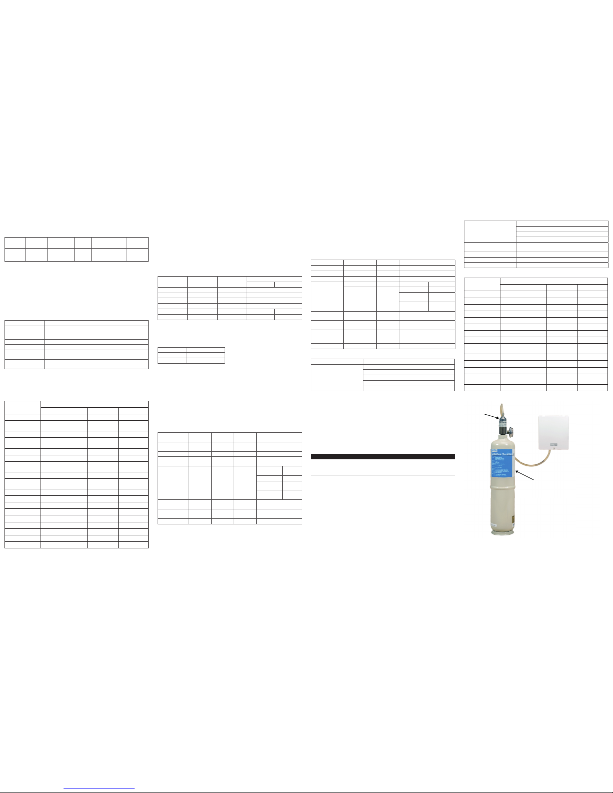
3. With the tubing connected to the regulator and cylinder, place tubing in the opening at the
bottom of this unit (see Figure 6).
4. Open the regulator and apply gas. This process may take up to five minutes.
5. If the unit is operating properly:
• The Red LED:
• illuminates when concentration level > Calibration Check level or Active Alarm level
• is visible through the upper and lower enclosure vents.
• the relay will activate if the Active Alarm level is exceeded.
6. Turn off regulator and remove tubing from opening.
7. Allow gas level to return to normal.
8. Reactivate any equipment connected to the outputs or reconnect the wiring to the outputs.
9. Remember to restore any alarm level settings that may have been changed for the Calibration
Check.
Device Management Dynamic Device Binding-B (DM-DDB-B)
Dynamic Object Binding-B (DM-DOB-B)
Device Communication Control-B (DM-DCC-B)
Reinitialize Device-B (DM-RD-B)
Data Link Layer Options MS/TP Master (Clause 9),
Baud Rates: 9600, 19200, 38400, 57600, 76800, 115200
Static device binding Supported NO
Character Sets Supported ISO 10646 (UTF-8)
Segmentation Capability NO
BACnet Standard Object Types supported:
Property Object Type
Device Analog Input Analog Values
Object Identifier R R R
Object Name R R R
Object Type R R R
System Status R
Vendor Name R
Vendor Identifier R
Model Name R
Firmware Revision R
App Software
Revision
R
Protocol Version R
Protocol Revision R
Services Supported R
Object Type
Supported
R
Object List R
.25 LPM
REGULATOR
467895
SPAN OR ZERO
GAS CYLINDER
Figure 6: Applying Calibration Gas
 Loading...