

Page 1
CHILLGARD® M-100
Refrigerant Sensor
Operating Manual
Order No.: 10086391/02
GB
Page 2

For the Declaration of Conformity, please visit the product page on MSAsafety.com.
MSA Europe GmbH
Schlüsselstrasse 12
8645 Rapperswil-Jona
Switzerland
© MSA 2017. All rights reserved
Page 3

MSA CONTENTS
Contents
1. Safety Regulations ................................................................................................................................................ 4
1.1. Correct Use .................................................................................................................................................. 4
1.2. Liability Information ....................................................................................................................................... 4
2. Description ............................................................................................................................................................. 5
2.1. Locating the Sensor ...................................................................................................................................... 6
2.2. Mounting the Sensor ..................................................................................................................................... 6
3. Calibration ............................................................................................................................................................ 11
3.1. Calibration Check ....................................................................................................................................... 11
3.2. Calibration Gases ....................................................................................................................................... 11
3.3. Calibration Procedure ................................................................................................................................. 12
4. Operation ............................................................................................................................................................. 13
4.1. Optical Indication ........................................................................................................................................ 13
4.2. Control Modules .......................................................................................................................................... 13
4.3. RS-485 Output Specifications ..................................................................................................................... 14
4.4. RS-485 Addressing (if applicable) ............................................................................................................... 15
4.5. Gas Selection Jumpers ............................................................................................................................... 15
5. Technical Specifications ..................................................................................................................................... 16
6. Ordering Information ........................................................................................................................................... 18
GB
Chillgard M-100 3
Page 4
SAFETY REGULATIONS MSA
1. Safety Regulations
1.1. Correct Use
MSA’s CHILLGARD
present of the most common halogenated refrigerants in cold storage facilities, mechanical equipment rooms and
other refrigerant applications.
It is imperative that this operating manual be read and observed when using the sensor. In particular, the safety
instructions, as well as the information for the use and operation of the apparatus, must be carefully read and
observed. Furthermore, the national regulations applicable in the user's country must be taken into account for a
safe use.
Danger!
This product is supporting life and health. Inappropriate use, maintenance or servicing may affect the
function of the device and thereby seriously compromise the user’s life.
Before use, the product operability must be verified. The product must not be used if the function test is
unsuccessful, it is damaged, a competent servicing/maintenance has not been made, genuine MSA spare
parts have not been used.
Alternative use, or use outside this specification will be considered as non-compliance. This also applies especially
to unauthorised alterations to the apparatus and to commissioning work that has not been carried out by MSA or
authorised persons.
1.2. Liability Informatio n
MSA accepts no liability in cases where the product has been used inappropriately or not as intended. The
selection and use of the product are the exclusive responsibility of the individual operator.
Product liability claims, warranties also as guarantees made by MSA with respect to the product are voided, if it is
not used, serviced or maintained in accordance with the instructions in this manual.
®
M-100 Refrigerant Sensor – hereinafter referred to as sensor – is designed to detect the
4 Chillgard M-100
GB
Page 5
MSA DESCRIPTION
2. Description
2
1
3
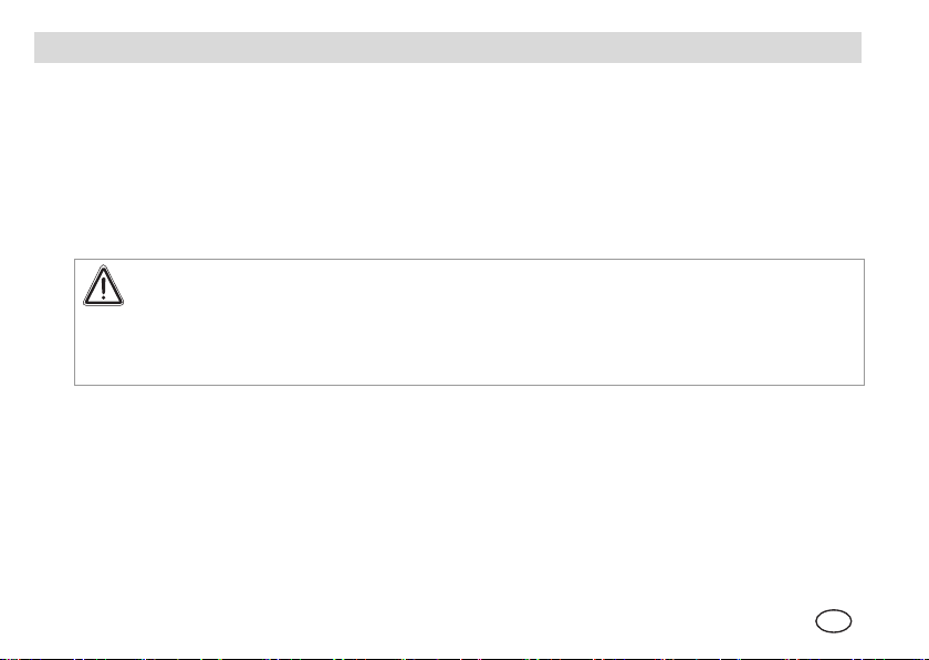
Fig. 1 Sensor Base and Cover
Check the label provided on the printed circuit board ( Fig. 1) to identify the assemble to order (ATO) code.
ATTENTION!
The sensor is set at the factory to detect only one defined type of gases ( ATO code).
This setting can not be changed during use.
The sensor is available with a number of options including:
Refrigerant gas detected
Temperature and Relative Humidity sensors
Output – current or voltage analogue output or RS-485 ModBUS digital output
De-icer option – for low temperature applications.
GB
Chillgard M-100 5
1 Base
2 ATO Code
3 Cover
Page 6
DESCRIPTION MSA
2.1. Locating the Sensor
Proper sensor location is necessary to ensure accurate measurement of representative air samples.
Locate the sensor:
Indoors in a room area where air circulates freely
On a flat, interior surface
Approximately 30 - 45 cm from floor.
Do not locate the sensor:
Near heat sources, such as appliances, direct sunlight or concealed pipes or chimneys
On walls or structures subject to excessive vibration
In areas where air does not circulate freely, such as behind doors or in corners.
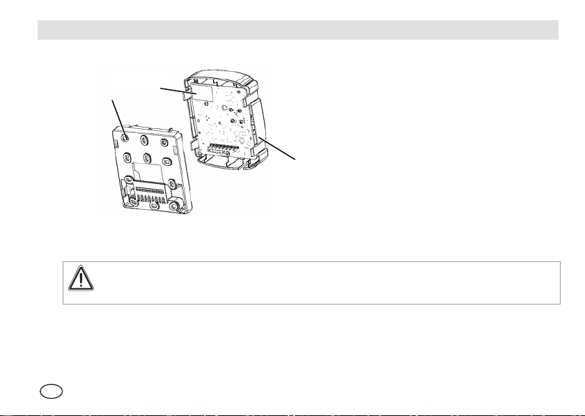
2.2. Mounting the Sensor
60.3
58.2
59.9
80.6
55.9
Fig. 2 Installation Dimensions
6 Chillgard M-100
GB
Page 7

MSA DESCRIPTION
WARNING!
The unit must always be powered by either a suitable UL 60950/CSA Certified power supply which is
isolated from line voltage by double insulation, or an appropriately rated UL listed/CSA Certified Class 2
transformer. Failure to follow the above can result in serious injury or loss of life.
The sensor consists of two basic parts, the base and the cover ( Fig. 1). The cover incorporates the electronics
with the sensing elements.
(1) Mark four holes as shown in Fig. 2.
(2) Drill holes of appropriate diameter for wall plugs.
(3) Remove the cover from the base and
(4) Attach base with screws of appropriate diameter.
(5) Fasten the base to a junction box or other support.
The base has a number of openings to allow for mounting to various junction boxes.
(6) Feed the power and signal wires through the rectangular opening in the base.
(7) Connect the wires to the terminal connector located in the base, as indicated in Fig. 3.
See also Wiring Connections in Fig. 5.
(8) If RS-485 sensors are being tied into a control device, insert a two-position jumper into J6 on the sensor board
that is wired farthest from the controller. This enables the RS-485 termination resistor.
(9) Align the two side tabs of the cover with the base and snap the cover onto the base.
(10) Verify cover is securely attached to base by pulling on the top and bottom of the cover as shown in Fig. 4.
To remove the cover, grasp it along the recesses and pull it away from the base ( Fig. 4).
Alternatively, place a screwdriver into the slots indicated in Fig. 4 and twist.
GB
Chillgard M-100 7
Page 8

DESCRIPTION MSA
2
1
1
OR
4
3
Fig. 3 Connecting Wires to Terminal
Fig. 4 Attaching or Removing the Cover
Connector
(1) Grasp here to release (4 places)
(2) Pull on top to verify attachment
(3) Pull on bottom to verify attachment
8 Chillgard M-100
(4) Twist to release (4 places)
GB
Page 9

MSA DESCRIPTION
----- Current Output -----
Fig. 5 Wiring Connections
GB
Chillgard M-100 9
----- Voltage Output -----
MSA
ModBUS
Label
Page 10

DESCRIPTION MSA
24 VAC 24 V AC line or 24 V DC+
ACN 24 V AC Neutral 24 V DC-
Gas out (mA) Gas reading as current (4 – 20 mA = 0 – 1000 ppm)
Gas (+) out (V) Gas reading as voltage (2 – 10 V = 0 – 1000 ppm)
RH out (mA) Relative humidity as current (4 – 20 mA = 0 – 100 % RH)
RH (+) out (V) Relative humidity as voltage (2 – 10 V = 0 – 100 % RH)
Temp out (mA) Temperature as current (4 – 20 mA = -30 °C to +70 °C)
Temp (+) out (v) Temperature as voltage (2 – 10 V = -30 °C to +70 °C)
RS-485 out b RS-485 ModBUS (b)
RS-485 out a RS-485 ModBUS (a)
Circuit common/analog signal reference (internally tied to ACN)
Earth ground (tie to user earth connection)
10 Chillgard M-100
GB
Page 11

MSA CALIBRATION
3. Calibration
3.1. Calibration Check
The sensor is designed to operate for long periods of time with no zero drift. However, the sensor should be
checked periodically to verify that the unit detects refrigerant gas. The calibration check can be done with the use
of the following MSA equipment:
(P/N 603806) Polyurethane Tubing
(P/N 467896) 1.5 LPM regulator.
A calibration check of the sensor requires a supply of:
ZERO GAS (air or nitrogen) - Ambient air may be used if it does not contain refrigerant gas or an interfering
component
SPAN GAS Cylinder comprised of 100 ppm of the refrigerant gas of interest.
3.2. Calibration Gases
Description Concentration
R-123 in Nitrogen 100 ppm
R-134a in Nitrogen 100 ppm
R-22 in Nitrogen 100 ppm
R-404a in Nitrogen 100 ppm
GB
Chillgard M-100 11
Page 12

CALIBRATION MSA
3.3. Calibration Procedure
CAUTION!
If any control instruments connected sensor are wired to external devices (e.g., horns, exhaust fans, and
fire suppression systems), these devices may activate during the following procedures. To prevent
activating these devices while adjusting the sensor, disconnect the wiring to the control device. Return all
wiring to the control device when the calibration procedure is completed.
To verify that the sensor is operating properly:
(1) Deactivate any equipment connected to the outputs, or
1
disconnect the wiring of the outputs.
(2) With the tubing connected to the regulator and cylinder,
place tubing in the opening at the bottom of the sensor
( Fig. 6).
(3) Open the regulator and apply gas for a minimum of five
2
minutes.
(4) If the unit is operating properly, the red LED:
illuminates when concentration level is > 50 ppm
is visible through the calibration check opening.
(5) Turn OFF regulator and remove tubing from opening.
(6) Allow gas level to return to normal.
(7) Reactivate any equipment connected to the outputs or
reconnect the wiring to the outputs.
Fig. 6 Applying Calibration Gas
1 Regulator 1.5 LPM (P/N 467896)
2 Span Or Zero Gas Cylinder
12 Chillgard M-100
GB
Page 13

MSA OPERATION
4. Operation
4.1. Optical Indication
The sensor has three LEDs located at the bottom-left for quick unit status indication:
LED Indication
Green Lights during normal operation
Red Flashes at 0.5 Hz during start-up.
Turns ON solid when concentration reading exceeds 50 ppm
Yellow Flashes at 0.5 Hz when power supplied is outside limits.
4.2. Control Modules
The sensor output can be connected with a control module providing a complete monitoring system ( Operating
Manual of the control module).
During a fault, the:
current output drops to 2 mA or
voltage output drops to 1 V.
GB
Chillgard M-100 13
Turns ON solid during other fault condition
Page 14

OPERATION MSA
4.3. RS-485 Output Specifications
Register Name PDU Address LOGICAL Address Range
Fault and Module State 0x0000 1 Under Range 2 (msb)
Under Voltage 8 (msb)
Temperature 10 (msb)
Lamp Fail 40 (msb)
Test Mode 80 (msb)
Warm Up Complete 0 (lsb)
Cal/Setup 2 (lsb)
Factory Mode 4 (lsb)
Trouble Mode 8 (lsb)
Gas Number 0x0001 2 0 to 40 (see below)
Gas Concentration 0x0002 3 -20 to 1050 (ppm)
Temperature 0x002C 45 -300 to +650 (°C * 10)
Humidity 0x002D 46 0 to 100 (%RH)
Gas Numbers R-22 = 6,
R-123 = 12
Baud rate: 19,200; each byte is eight bits with no parity and two stop bits.
R-404a = 27
R-134a = 15
14 Chillgard M-100
GB
Page 15

MSA OPERATION
4.4. RS-485 Addressing (if applicable)
In Fig. 7 are shown the jumper settings for the 12 user configurable RS-485 addresses.
MODBUS ADDRESS JUMPER SETTINGS
J5 J4 J3 J5 J4 J3 J5 J4 J3
100
101
102
103
Fig. 7 Jumper Settings for the RS-485-Addresses
4.5. Gas Selection Jumpers
On R-22, R-404A and R-134A the gas of interest can be changed by altering the Position of jumpers J1 and J2 as
shown in Fig. 8.
Fig. 8 Gas Selection Jumper Settings
GB
Chillgard M-100 15
104
105
106
107
108
109
110
111
Page 16

TECHNICAL SPECIFICATIONS MSA
5. Technical Specifications
Size 115.06 mm x 90,93 mm x 36.07 mm
Weight 160 g
Power Requirements 24 V DC, +20%, 24 V AC +20%, 50/60 Hz, Class 2, UL 60950/CSA certified
Power Consumption < 2.7 watts
Wiring up to 2,5 mm², Class 2 copper wiring
Output Options 4 to 20 mA sourcing, <500 Ohm load
Operating Temperature 0 to 65°C (-30 degrees lower temp specification with de-icer option)
Relative Humidity (RH) 0 to 99% non-condensing
Pressure Operating 700 -1080 hPa
Warm-up time 30 minutes
Pollution Degree 2
Installation Category II
Operating Range 0 to 1000 ppm
Limit of Detection 20 ppm
Minimum Alarm 50 ppm
2 - 10 V, 10 kOhm load RS-485 ModBUS RTU
16 Chillgard M-100
GB
Page 17

MSA TECHNICAL SPECIFICATIONS
Response Time t50 < 270 seconds
Repeatability ±10 ppm at 50 ppm
Linearity ±10 ppm from 25-50 ppm, +20% of reading from 50 to 1000 ppm
Temperature Sensor ±0.4°C at 25°C
Humidity Sensor ±3% RH at 50% RH and 25°C
Standard Gases *) R22, R123, R134a, R404a
Approvals
CE approval, complies with the applicable LVD and EMC directives
(see also Declaration of Conformity)
Certified to UL Std 61010-1 and CSA 61010
Complies with ASHRAE 15-2004
*) Other gases are available. Please check with factory for availability.
GB
Chillgard M-100 17
Page 18

ORDERING INFORMATION MSA
6. Ordering Information
Description Part No.
R-22 in Nitrogen 10086542
R-123 in Nitrogen 10086543
R-134a in Nitrogen 10086544
R-404A in Nitrogen 10086545
18 Chillgard M-100
GB
Page 19

MSA ORDERING INFORMATION
GB
Chillgard M-100 19
Page 20

For local MSA
contacts, please visit us at MSAsafety.com
 Loading...