

Page 1

Chillgard® LS
Refrigerant Monitor
Instruction Manual
THIS MANUAL MUST BE CAREFULLY READ BY ALL INDIVIDUALS WHO HAVE OR WILL
HAVE THE RESPONSIBILITY FOR USING OR SERVICING THE PRODUCT. Like any piece
of complex equipment, this instrument will perform as designed only if it is used and
serviced in accordance with the manufacturer’s instructions. OTHERWISE, IT COULD
FAIL TO PERFORM AS DESIGNED AND PERSONS WHO RELY ON THIS PRODUCT FOR
THEIR SAFETY COULD SUSTAIN SEVERE PERSONAL INJURY OR DEATH.
The warranties made by Mine Safety Appliances Company with respect to the product
are voided if the product is not used and serviced in accordance with the instructions in
this manual. Please protect yourself and others by following them. We encourage our
customers to write or call regarding this equipment prior to use or for any additional
information relative to use or repairs.
IN NORTH AMERICA: 1-800-MSA-INST. or FAX (724) 776-9783
IN CANADA: 1-800-267-0672 or FAX (416) 663-5908
MSA INTERNATIONAL (412) 967-3354 or FAX (412) 967-3373
© MINE SAFETY APPLIANCES COMPANY 2009 - All Rights Reserved
This manual is available on the internet at www.msanet.com
Manufactured by
MSA NORTH AMERICA
P.O. Box 427, Pittsburgh, Pennsylvania 15230
(L) Rev 7 10035164
"
WARNING
Page 2
i
Chillgard LS Diffusion Refrigerant Monitor
Chillgard LS Pumped Refrigerant Monitor
Page 3

MSA Permanent Instrument Warranty
1. Warranty- Seller warrants that this product will be free from
mechanical defect or faulty workmanship for a period of two years
from date of shipment, provided it is maintained and used in
accordance with Seller's instructions and/or recommendations. This
warranty does not apply to expendable or consumable parts whose
normal life expectancy is less than one (1) year such as, but not
limited to, non-rechargeable batteries, filament units, filter, lamps,
fuses etc. The Seller shall be released from all obligations under
this warranty in the event repairs or modifications are made by
persons other than its own or authorized service personnel or if the
warranty claim results from physical abuse or misuse of the
product. No agent, employee or representative of the Seller has
any authority to bind the Seller to any affirmation, representation or
warranty concerning the goods sold under this contract. Seller
makes no warranty concerning components or accessories not
manufactured by the Seller, but will pass on to the Purchaser all
warranties of manufacturers of such components.
THIS WARRANTY IS IN LIEU OF ALL OTHER WARRANTIES,
EXPRESSED, IMPLIED OR STATUTORY, AND IS STRICTLY
LIMITED TO THE TERMS HEREOF. SELLER SPECIFICALLY
DISCLAIMS ANY WARRANTY OF MERCHANT ABILITY OR OF
FITNESS FOR A PARTICULAR PURPOSE.
2. Exclusive Remedy- It is expressly agreed that Purchaser's sole
and exclusive remedy for breach of the above warranty, for any
tortious conduct of Seller, or for any other cause of action, shall be
the repair and/or replacement at Seller's option, of any equipment
or parts thereof, which after examination by Seller is proven to be
defective. Replacement equipment and/or parts will be provided at
no cost to Purchaser, F.O.B. Seller's Plant. Failure of Seller to
successfully repair any non-conforming product shall not cause the
remedy established hereby to fail of its essential purpose.
3. Exclusion of Consequential Damage- Purchaser specifically
understands and agrees that under no circumstances will seller be
liable to purchaser for economic, special, incidental or
consequential damages or losses of any kind whatsoever, including
but not limited to, loss of anticipated profits and any other loss
caused by reason of non-operation of the goods. This exclusion is
applicable to claims for breach of warranty, tortious conduct or any
other cause of action against seller.
ii
Page 4

1. Each instrument described in this manual must be installed,
operated, and maintained in strict accordance with its labels,
cautions, warnings, instructions, and within the limitations stated.
2. These monitors must not be installed in outdoor areas or in areas
or locations where explosive concentrations of combustible gases
or vapors might occur in the atmosphere: Class 1, Group A, B, C,
and D areas as defined by the NEC. Because the monitors are not
explosion-proof, they must be located in non-hazardous areas.
3. The Chillgard LS Refrigerant Monitor is designed to detect
refrigerant gases in the air. It cannot measure the concentration of
these gases in a steam type atmosphere.
4. As with all gas detection instruments of this type, high levels of or
long exposure to certain compounds in the tested atmosphere
contaminate the sensor. In atmospheres where the monitor may be
exposed to such materials, calibration must be performed
frequently to ensure that system operation is dependable and its
indications accurate.
5. The Chillgard LS Refrigerant Monitor must not be painted.
Painting will interfere with the sampling process of the instrument.
If painting is being done in an area where the instrument is located,
care must be exercised to insure that paint is not put or splashed
on the instrument.
6. The only absolute method to assure the proper overall operation
of a gas detection instrument is to check it with a known
concentration of the gas for which it has been calibrated.
Consequently, a calibration check must be included as part of
the routine inspection of the system.
7. The sensor is a sealed unit. Do not attempt to modify or adjust the
sensing cell.
8. Use only genuine MSA replacement parts when performing any
maintenance procedures provided in this manual. Failure to do so
may seriously impair instrument performance. Repair or alteration
of the Chillgard LS Refrigerant Monitor, beyond the scope of these
maintenance instructions or by anyone other then an authorized
MSA service person, could cause the product to fail to perform as
designed, and persons who rely on this product for their safety
could sustain serious personal injury or death.
9. Ensure that the Chillgard LS Refrigerant Monitor is installed in a
clean and dry area as possible.Install splash or rain shields on the
instrument to keep water and other contaminants away from the
instrument. If you fail to follow this warning, equipment damage
can occur.
iii
"!
WARNINGS
Page 5

10.Ensure that the Chillgard LS Refrigerant Monitor and the area the
instrument is monitoring is at the same temperature before
operation of the instrument; otherwise, condensation will form and
possibly clog or fill the gas sensor in the instrument rendering the
instrument inoperable.
11. Protect the Monitor from vibration and heating; otherwise, improper
operation may result, which can result in personal injury or death.
FAILURE TO FOLLOW THE ABOVE WARNINGS CAN RESULT IN SERIOUS
PERSONAL INJURY OR DEATH.
iv
Page 6

v
Table of Contents
Chapter 1
General Information . . . . . . . . . . . . . . . . . . . .1-1
Figure 1-1. Identification Label Location . . . . . . . . .1-1
Terminology Used in this Manual . . . . . . . . . . . . . . . . . .1-2
General Description . . . . . . . . . . . . . . . . . . . . . . . . . . . .1-3
Applications . . . . . . . . . . . . . . . . . . . . . . . . . . . . . . . . . .1-3
Table 1-1. General Operating Specifications
for all Models . . . . . . . . . . . . . . . . . . . . . . . . .1-4
Table 1-2. Typical Chillgard LS / R-11
Cross-Sensitivity Response Data . . . . . . . . . .1-5
Table 1-3. Typical Chillgard LS / R-12
Cross-Sensitivity Response Data . . . . . . . . . .1-5
Table 1-4. Typical Chillgard LS / R-22
Cross-Sensitivity Response Data . . . . . . . . . .1-6
Table 1-5. Typical Chillgard LS / R-123
Cross-Sensitivity Response Data . . . . . . . . . .1-6
Table 1-6. Typical Chillgard LS / R-134 A
Cross-Sensitivity Response Data . . . . . . . . . .1-7
Chapter 2
Installation and Set-up . . . . . . . . . . . . . . . . . .2-1
Unpacking the System . . . . . . . . . . . . . . . . . . . . . . . . . .2-1
Initial Inspection . . . . . . . . . . . . . . . . . . . . . . . . . . . . . . .2-1
Sensor Location . . . . . . . . . . . . . . . . . . . . . . . . . . . . . .2-1
Pumped Units . . . . . . . . . . . . . . . . . . . . . . . . . . . . . . .2-1
Diffusion Units . . . . . . . . . . . . . . . . . . . . . . . . . . . . . . .2-2
" CAUTION . . . . . . . . . . . . . . . . . . . . . . . . . . . . . .2-2
Mounting the Unit . . . . . . . . . . . . . . . . . . . . . . . . . . . . . .2-3
Five rules for proper mounting . . . . . . . . . . . . . . . . . . .2-3
Mounting . . . . . . . . . . . . . . . . . . . . . . . . . . . . . . . . . . .2-3
" WARNING . . . . . . . . . . . . . . . . . . . . . . . . . . . . .2-3
Figure 2-1. Diffusion Style Mounting Dimensions . .2-4
Figure 2-2. Four-Point Pumped Style
Mounting Dimensions . . . . . . . . . . . . . . . . . . .2-5
Page 7

Wiring Connections . . . . . . . . . . . . . . . . . . . . . . . . . . . .2-6
Opening the Unit . . . . . . . . . . . . . . . . . . . . . . . . . . . . .2-6
Wiring . . . . . . . . . . . . . . . . . . . . . . . . . . . . . . . . . . . . . .2-6
" CAUTION . . . . . . . . . . . . . . . . . . . . . . . . . . . . . .2-6
" CAUTION . . . . . . . . . . . . . . . . . . . . . . . . . . . . . .2-6
Figure 2-3. Diffusion Style Electrical Connections . .2-7
Figure 2-4. Four-Point Pumped Style
Electrical Connections . . . . . . . . . . . . . . . . . .2-7
For 24 V DC or AC Wiring . . . . . . . . . . . . . . . . . . . . . .2-8
For 110/220 VAC Wiring . . . . . . . . . . . . . . . . . . . . . . .2-8
Figure 2-5. Sensor Board Connections . . . . . . . . . .2-8
Analog Signal Output Wiring . . . . . . . . . . . . . . . . . . . .2-9
Chapter 3
Start-up and Initial Adjustments . . . . . . . . . .3-1
Operation . . . . . . . . . . . . . . . . . . . . . . . . . . . . . . . . . . . .3-1
Start-Up . . . . . . . . . . . . . . . . . . . . . . . . . . . . . . . . . . . .3-1
General Calibration (All Models) . . . . . . . . . . . . . . . . .3-1
Introduction . . . . . . . . . . . . . . . . . . . . . . . . . . . . . . . . .3-1
Chapter 4
Calibration . . . . . . . . . . . . . . . . . . . . . . . . . . . .4-1
Figure 4-1. Calibration Equipment . . . . . . . . . . . . . .4-1
" WARNING . . . . . . . . . . . . . . . . . . . . . . . . . . . . .4-1
Diffusion Version Calibration . . . . . . . . . . . . . . . . . . . . .4-1
Calibration Equipment - (FIGURE 4-1) . . . . . . . . . . . .4-1
Initial Calibration Procedures . . . . . . . . . . . . . . . . . . . .4-2
Preparation for Calibration . . . . . . . . . . . . . . . . . . . . . .4-2
Initial Calibration . . . . . . . . . . . . . . . . . . . . . . . . . . . . .4-2
" CAUTION . . . . . . . . . . . . . . . . . . . . . . . . . . . . . .4-2
" CAUTION . . . . . . . . . . . . . . . . . . . . . . . . . . . . . .4-2
Figure 4-2. Applying Calibration Gas
to the Chillgard LS Refrigerant Monitor . . . . .4-3
Calibration Guidelines . . . . . . . . . . . . . . . . . . . . . . . . .4-4
Calibration Equipment . . . . . . . . . . . . . . . . . . . . . . . . .4-4
Calibration Check Procedure . . . . . . . . . . . . . . . . . . . .4-5
Applying Calibration Gases to the Instrument . . . . . . .4-5
vi
Page 8

" CAUTION . . . . . . . . . . . . . . . . . . . . . . . . . . . . . .4-5
Four-Point Pumped Version Calibration . . . . . . . . . . . . .4-6
Introduction . . . . . . . . . . . . . . . . . . . . . . . . . . . . . . . . .4-6
Calibration Equipment . . . . . . . . . . . . . . . . . . . . . . . . .4-6
" CAUTION . . . . . . . . . . . . . . . . . . . . . . . . . . . . . .4-6
Figure 4-3. Kit Components . . . . . . . . . . . . . . . . . . .4-7
" CAUTION . . . . . . . . . . . . . . . . . . . . . . . . . . . . . .4-7
Table 4-1. RP Calibration Gases . . . . . . . . . . . . . .4-8
Calibration Procedures . . . . . . . . . . . . . . . . . . . . . . . .4-8
Preparation for Calibration . . . . . . . . . . . . . . . . . . . . . .4-8
" CAUTION . . . . . . . . . . . . . . . . . . . . . . . . . . . . . .4-8
" WARNING . . . . . . . . . . . . . . . . . . . . . . . . . . . . .4-8
" CAUTION . . . . . . . . . . . . . . . . . . . . . . . . . . . . . .4-8
Initial Calibration . . . . . . . . . . . . . . . . . . . . . . . . . . . . .4-9
Calibration Guidelines . . . . . . . . . . . . . . . . . . . . . . . . .4-9
Calibration Equipment . . . . . . . . . . . . . . . . . . . . . . . .4-10
Calibration Check Procedure . . . . . . . . . . . . . . . . . . .4-10
Zeroing the Monitor . . . . . . . . . . . . . . . . . . . . . . . . . .4-10
" WARNING . . . . . . . . . . . . . . . . . . . . . . . . . . . .4-10
Figure 4-4. Using Zero Scrubber
for Zero Calibration . . . . . . . . . . . . . . . . . . . .4-11
Figure 4-5. Using Zero Gas Cylinder
for Zero Calibration . . . . . . . . . . . . . . . . . . . .4-11
Figure 4-6. Span Calibration . . . . . . . . . . . . . . . . .4-12
" CAUTION . . . . . . . . . . . . . . . . . . . . . . . . . . . . .4-12
" CAUTION . . . . . . . . . . . . . . . . . . . . . . . . . . . . .4-13
Chapter 5
Service and Replacement Parts . . . . . . . . . .5-1
Troubleshooting Guidelines . . . . . . . . . . . . . . . . . . . . . .5-1
Table 5-1.Troubleshooting Guidelines . . . . . . . . . .5-1
Table 5-2. Calibration Accessories Parts List . . . . .5-2
Table 5-3. Replacement Parts List . . . . . . . . . . . . .5-3
Service and Assistance . . . . . . . . . . . . . . . . . . . . . . . . .5-4
vii
Page 9

Appendix A
Installation Outline Drawings . . . . . . . . . . . .A-1
Figure A-1. Diffusion Style Chillgard LS
Installation Drawing . . . . . . . . . . . . . . . . . . . .A-1
Appendix B
RS-485 Output . . . . . . . . . . . . . . . . . . . . . . . .B-1
Table B-1. Dip Switch Positions . . . . . . . . . . . . . . .B-1
Table B-2. Sensor Unit Register Addresses . . . . .B-2
viii
Page 10
1-1
Chapter 1
General Information
The Chillgard LS Refrigerant Monitor provides a continuous indication of
a refrigerant concentration in air. It is capable of monitoring a refrigerant
from 0 to 1000 parts per million (ppm). Each instrument is factorycalibrated to a certain full-scale value of a specific refrigerant.
All Chillgard LS Refrigerant Monitors use infrared photo-acoustic
sensors. These sensors give an indication of refrigerant levels without
requiring oxygen to be present. Also, the sensors are not poisoned or
degraded in the presence of most silicon or sulfur compounds.
Each Chillgard LS Refrigerant Monitor is placed in an area where a
refrigerant is anticipated or must be controlled. The Monitor operates in
either the Diffusion style (gas diffuses into the sensor through the
opening located at the bottom of the unit) or the Pumped style (an
internal pump draws the sample into the sensor from a remote location).
The gas sensor determines the refrigerant concentration and outputs an
electrical analog signal proportionate to the concentration.
The Chillgard LS Refrigerant Monitor contains all components
necessary to properly sample an area or duct for a refrigerant.
This manual describes all of the various Chillgard LS Refrigerant
Monitors, although your monitor may not be equipped with all of the
options available.
To help determine what options are on your unit, see the identification
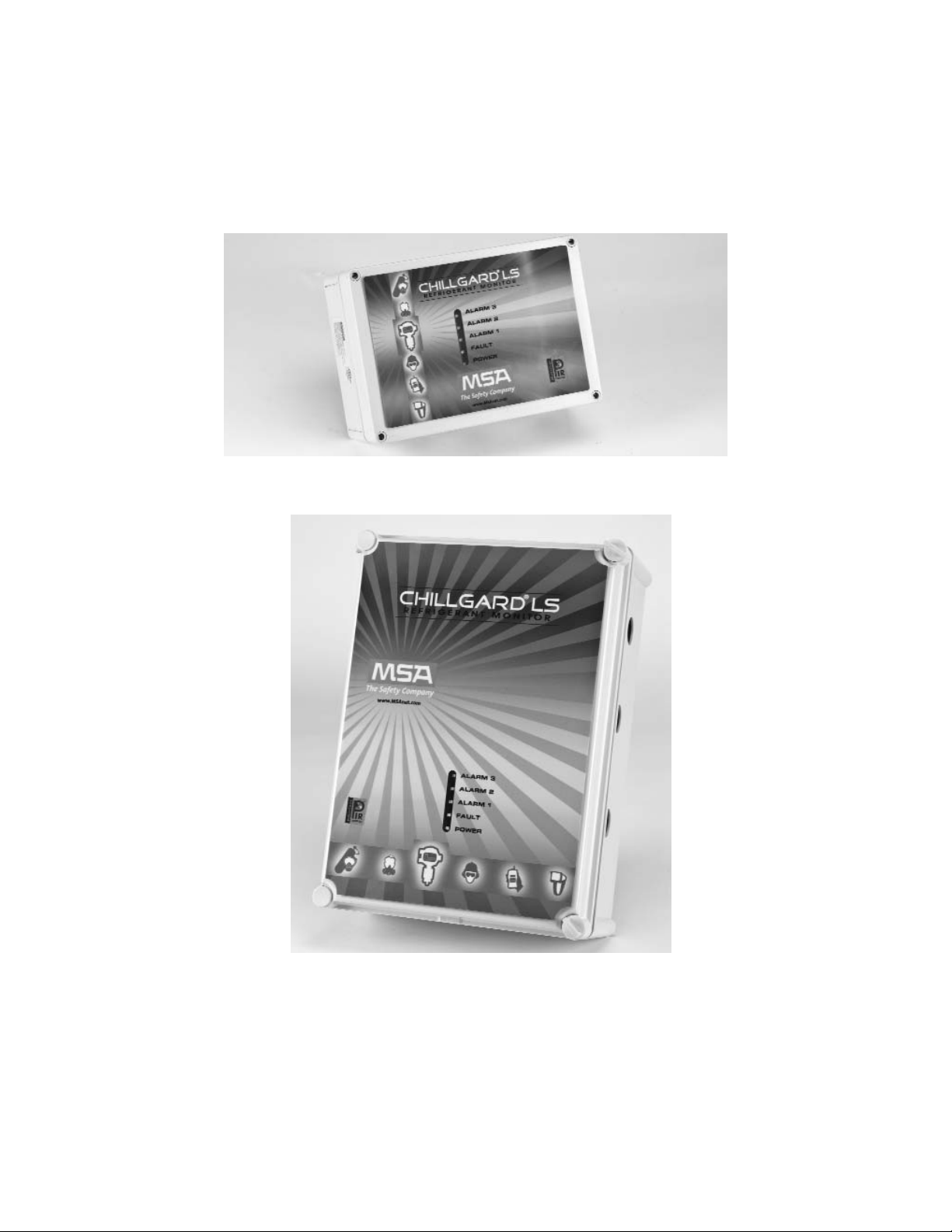
label on the side of the instrument (FIGURE1-1).
Figure 1-1. Identification Label Location
Page 11

1-2
This label contains:
• model number
• the refrigerant that the unit will detect
• information concerning proper voltages and frequency
required to power the unit
Terminology Used in this Manual
FLOW RATE:
Volume of gas drawn through the sample line per minute.
EXHAUST GAS:
Sample gas after it passes through the sensor.
FRESH AIR:
Air that has no possibility of containing refrigerant gas. Contamination
with refrigerant gas would interfere with the calibration and the flushing
of the instrument.
ZERO:
A zero (0) output usually indicates ambient air present or no refrigerant
gases present.
SCRUBBER:
An activated carbon filter which removes and cleans the span gas in the
calibration operation prior to exhausting excess gas to ambient air.
ZEROING:
The process of placing a zero indication on the output of the instrument.
SPAN:
A full-scale or up-scale reading on the output of the instrument.
SPANNING:
The process of placing a full-scale or up-scale output of the instrument.
Page 12

SPAN GAS VALUE:
The gas “concentration” that gives the instrument a full-scale or upscale output; this value is usually printed on the gas cylinder.
General Description
The Chillgard LS Refrigerant Monitor:
• provides a continuous indication of a refrigerant
gas concentration
• operates on the photo acoustic principle, and measures the
concentration of a refrigerant in a complex mixture of
background gases.
In the photo acoustic principle, sample gas is delivered to an
enclosed chamber which is periodically bombarded with infrared
(IR) radiation. If the target gas is present, it absorbs IR with each
pulse of light. These pulses are miniature sound waves which are
picked up by a microphone. The sound level is directly proportional
to the target gas concentration present in the gas chamber.
• is capable of measuring a refrigerant 0 to 1000 ppm full scale
• is housed in a rugged plastic enclosure
• has a standard 4 to 20 mA and RS-485 output
• has five LEDs to indicate power, fault and alarm conditions
• is highly selective to enable operation in areas with varying
humidity or in areas containing other contaminants. It may be used
for applications requiring long-term stability and low maintenance.
Applications
The Chillgard LS Refrigerant Monitor is factory-calibrated for a
refrigerant and can be used for applications such as:
• ventilation control
• ambient air monitoring for health and safety purposes.
1-3
Page 13

Table 1-1. General Operating Specifications for all Models
PERFORMANCE SPECIFICATIONS
LINEARITY 20 to 100 ppm +5 ppm
100 to 1000 ppm +6% of reading
REPEATABILITY +8 ppm
WARM-UP TIME 10 minutes
RESPONSE TIME 50% of a step-change in < 70 seconds
OPERATING TEMP. 0 to 40oC (32 to 104oF)
TEMP. EFFECT < 4% / 10oC
RELATIVE HUMIDITY 0 to 95%, RH non-condensing
RH EFFECT R11: less than 3% full scale
Other refrigerants: less than 1.5% full scale
OPERATING SPECIFICATIONS
POWER REQUIREMENTS 24 VDC, +10%, -0%, .85A
24 VAC, +10%, 50/60 Hz, .80A
100 to 240 VAC, 50/60, Hz, .3A
ANALOG OUTPUT 4 to 20 mA, non-isolated, sourcing
DEFAULT ALARM VALUES R123: 50, 150, 300 ppm
Other applications: 50, 150, 1000 ppm
MAX. OUTPUT SIGNAL LOAD 500 ohms
DIMENSIONS 7.1" high x 10" wide x 4.25" deep
DIFFUSION VERSION (188 mm high x 110 mm wide x 70 mm deep)
DIMENSIONS 14.7" high x 11.2" wide x 5" deep
PUMPED VERSION (373 mm high x 284 mm wide x 127 mm deep)
WEIGHT DIFFUSION VERSION 3.7 pounds (1.678 kg.)
WEIGHT PUMPED VERSION 9.5 pounds (4.308 kg.)
SAMPLE FLOW RATE Typically 1.5 LPM; .
PUMPED VERSION .75 LPM with maximum tubing length
MAX. SAMPLE TUBING LENGTH PUMPED VERSION 300 feet with 1/8" ID tubing
MAX. EXHAUST TUBING LENGTH PUMPED VERSION 30 feet with 1/4" ID tubing
TRANSPORT AND STORAGE CONDITIONS
TEMP. -40 to 60oCentigrade (-40 to 140oF)
HUMIDITY 0 to 99% relative humidity
POLLUTION DEGREE AND INSTALLATION CATEGORY 2
ALTITUDE 2000 meters maximum
1-4
Page 14

Table 1-2. Typical Chillgard LS / R-11 Cross-Sensitivity Response Data
GAS CONCENTRATION (PPM) EQUIVALENT PPM R-11
Acetone 100 14
Methyl Ethyl Ketone 100 32
Methanol 1000 130
iso-Propanol 500 400
Methylene Chloride 100 0
Xylene 100 0
Ammonia 50 0
R-113 100 25
R-11 100 100
R-22 100 30
R-12 983 490
R-134 A 100 20
R-123 100 3
Propane 0.6% 18
Ethylene 500 20
TEST CONDITIONS: Calibrated 0-1000 PPM R-11 in N
2;
Temperature: 25OC
Table 1-3. Typical Chillgard LS / R-12 Cross-Sensitivity Response Data
GAS CONCENTRATION (PPM) EQUIVALENT PPM R-12
Acetone 100 3
Methyl Ethyl Ketone 1000 25
Methanol 1000 2
Methylene Chloride 1000 14
Trichloroethylene 1000 167
Ethyl Acetate 1000 22
Xylene (ortho-Xylene) 1000 5
R-113 100 35
R-11 100 5
R-22 100 1
R-12 100 100
R-134 A 100 2
R-114 100 45
TEST CONDITIONS: Calibrated 0-1000 PPM R-12 in N2; Temperature: 25OC
1-5
Page 15

Table 1-4. Typical Chillgard LS / R-22 Cross-Sensitivity Response Data
GAS CONCENTRATION (PPM) EQUIVALENT PPM R-22
Acetone 100 <1
R-11 100 16
R-123 100 35
R-134 A 100 25
R-132 A 100 40
R-22 100 100
R-113 100 39
TEST CONDITIONS: Calibrated 0-1000 PPM R-22 in N
2;
Temperature: 25OC
Table 1-5. Typical Chillgard LS / R-123 Cross-Sensitivity Response Data
GAS CONCENTRATION (PPM) EQUIVALENT PPM R-123
Acetone 100 22
Methyl Ethyl Ketone 500 48
Methanol 100 2
iso-Propanol 100 5
Methylene Chloride 1000 14
Trichloroethylene 1000 4
Ethyl Acetate 100 42
Xylene (ortho-Xylene) 1000 5
Ammonia 910 7
Natural Gas 1000 5
R-113 100 80
R-11 100 <1
R-22 100 4
R12 100 8
R-134 A 100 140
R-123 100 100
TEST CONDITIONS: Calibrated 0-1000 PPM R-123 in N
2;
Temperature: 25OC
1-6
Page 16

Table 1-6. Typical Chillgard LS / R-134 A Cross-Sensitivity Response Data
GAS CONCENTRATION (PPM) EQUIVALENT PPM R-134 A
Acetone 100 15
Methyl Ethyl Ketone 500 30
Methanol 100 1
iso-Propanol 100 3
Methylene Chloride 1000 10
Trichloroethylene 1000 3
Ethyl Acetate 100 28
Xylene (ortho-Xylene) 1000 3
Ammonia 910 5
Natural Gas 1000 3
R-113 100 55
R-11 100 <1
R-22 100 3
R12 100 6
R-134 A 100 100
R-123 100 70
TEST CONDITIONS: Calibrated 0-1000 PPM R-134 A in N
2;
Temperature: 25OC
1-7
Page 17

Chapter 2
Installation and Set-up
Unpacking the System
To unpack the Chillgard LS Refrigerant Monitor:
• Carefully remove the unit from its shipping container(s) to prevent
damage to sensitive electrical and gas sensing components.
• Search through packing material and inside of the containers to
prevent inadvertently discarding usable or valuable parts.
• Remove the plastic screws holding the cover to the enclosure.
• Remove the front cover from the Chillgard LS Refrigerant Monitor
to expose the electrical printed circuit board.
Initial Inspection
With the front cover open, carefully inspect the components and
assemblies inside the enclosure. If damage or shortage is noted,
promptly make the proper claim with the carrier.
Sensor Location
Pumped Units
Pumped units use an internal sample pump to pull refrigerant gas from
a remote location(s). The visual indication for the unit is located on the
front of the unit. Other outputs are available on the device which can be
used to provide indication of gas concentration, alarm status, and
instrument status.
Refrigerants concentrate near the floor. In typical mechanical equipment
room applications, sampling 12-18 inches above the floor is sufficient
for early warning and to provide adequate protection for someone
working close to the floor. If it is expected that an occupant's breathing
zone may be less than 12-18 inches off the floor, locate the sampling
point accordingly.
NOTE: Select sampling locations that result in the shortest possible line
length in order to reduce transport time.
Consider the following guidelines when selecting the location for the
sampling point(s).
2-1
Page 18

1. Most refrigerants are heavier than air and sink to the floor or
accumulate in low areas.
2. Place the end of the sampling line in an area that provides the
instrument with a representative sample; ventilation Smoke Tubes
(P/N 458480) are useful in determining air flow patterns in ambient
sampling areas.
3. Properly exhaust the instrument to a safe area or to outside
atmosphere.
4. Ensure the sampling area is free of particulate matter and
condensing moisture; ensure sample lines will not draw moisture
up into the line.
NOTE: The sample gas must be adequately filtered before
entering the instrument. End-of-sample-line filters must be
used with the unit. These filters must be installed at the
end of all sample lines.
5. Ensure the end of the sampling line is unobstructed to allow the
sample to flow freely to the instrument.
6. Keep sample lines as short as possible to reduce transport time.
Ensure that tubing radii are wide enough to prevent kinking
or bending. Otherwise, an obstruction may occur, preventing
the instrument from sampling the intended area.
7. DO NOT:
• back-pressure the exhaust line or
• connect it to a vacuum source or
• install a flow meter in the exhaust line.
ALWAYS :
connect an exhaust line that is vented to a safe area or
an outside atmosphere.
Diffusion Units
Diffusion units sample the refrigerant gas located at the base of the
refrigerant monitor. The visual indication for the unit is located on the
front of the unit. Other outputs are on the device can be used to provide
gas concentration, alarm status, and instrument status indications.
Consider the following guidelines when selecting the location for the
sampling point(s):
"
CAUTION
2-2
Page 19

1. Most refrigerants are heavier than air and sink to the floor or
accumulate in low areas.
2. Place the instrument in an area that provides it with a
representative sample; ventilation Smoke Tubes (P/N 458480) are
useful in determining air flow patterns in ambient sampling areas.
3. Ensure that the area around the instrument is unobstructed to
allow the sample to flow freely to the instrument.
4. If the unit’s visual indication is used to alert workers of potential
gas hazards, mount the instrument in a clearly visible location.
NOTE: The diffusion unit is appropriate for applications where the
indication panel is clearly visible with the unit mounted 12-18
inches off the floor; otherwise, a pumped unit located at eye
level with sensor points located 12-18 inches off the floor may
be more appropriate.
Mounting the Unit
Five Rules for Proper Mounting
1. Do not mount the unit to structures subject to vibration and shock.
2. Do not locate the unit near an excessive heat source.
3. For proper cooling, allow at least three inches of clearance around
all surfaces, except for the mounting surface.
4. Do not mount the unit where it will be exposed to direct solar
heating, rain and splashing water.
5. Mount the unit where it is accessible for maintenance.
Mounting
Do not mount more than one pumped unit to the same mounting
structure. Mechanical vibration produced from one unit can cause
improper gas readings on another unit.
Do not locate these units in an area that may contain a flammable mixture
of gas and air; otherwise, an explosion may occur.
Install the Chillgard LS Refrigerant Infrared Monitor in the area where a
refrigerant is anticipated or control of the gas is desired.
Ventilation Smoke Tubes (P/N 458480) are useful in determining air flow
patterns in ambient sampling areas.
"
WARNING
2-3
Page 20

1. Open the unit by removing the plastic screws securing the lid to the
enclosure.
2. Using #10 mounting screws or bolts (FIGURES 2-1 and 2-2),
securely mount the Chillgard LS Refrigerant Monitor to a wall or
flat mounting surface via the four holes that run through the
enclosure base.
3. When applying an external sample line to the pumped unit, use the
fittings provided at the bottom of the enclosure. Do not place any
restriction on the exhaust port located on the right side of the
enclosure. Do not place greater than 30 feet of tubing on the
exhaust port located on the bottom right of the enclosure.
4. Reinstall the cover to the unit.
Figure 2-1. Diffusion Style Mounting Dimensions
2-4
Page 21

Figure 2-2. Four-Point Pumped Style Mounting Dimensions
2-5
Page 22

Wiring Connections
Opening the Unit
See Appendix A, "Installation Outline Drawings" for wire entry hole
locations.
Do not open the cover unless the monitor is protected from splashing,
spraying, or dripping water; otherwise, damage to the internal
components may result.
Wiring
The Chillgard LS Refrigerant Monitor is factory-wired with either a
universal power supply for 110/220 VAC operation or no power supply
for 24 V AC/DC operation. Refer to FIGURE 1-1 to determine power
requirement for the unit.
The following steps outline the procedure for connecting the wiring:
1. Determine the power supply for your Chillgard LS Refrigerant
Monitor (FIGURE 1-1).
If unsure of the power voltage available, contact your facility engineer or
safety officer. Instrument damage may occur if incorrect power voltage is
applied to the instrument.
NOTE: External overcurrent shall be included in the building instal-
lation, shall be in close proximity to the equipment and
within easy reach of the operator, and shall be marked as
the disconnecting device for the equipment.
All power wiring is connected to the terminal block (FIGURE 2-2
and FIGURE 2-3).
"
CAUTION
"!
CAUTION
2-6
Page 23

Figure 2-4. Four-Point Pumped Style Electrical Connections
Figure 2-3. Diffusion Style Electrical Connections
2-7
Page 24

For 24 V DC or AC Wiring
NOTE: The 24-volt power source used with this equipment must be
separated from mains by double or reinforced insulation.
All power wiring is connected to the terminal block for 24 V DC/AC input
shown in FIGURE 2-5.
For 110/220 VAC Wiring
All power wiring is connected to the two-position terminal block shown
in FIGURES 2-3 or 2-4.
2. Connect the "HOT" AC wire to the terminal with the black wire (or
brown wire for instruments with a line filter).
3. Connect the "NEUTRAL" AC wire to the terminal with the white
wire (or blue wire for instruments with a line filter).
Figure 2-5. Sensor Board Connections
2-8
Page 25

4. Connect a ground wire on the ground stud (FIGURE 2-4).
Supply earthground is installed on lug first, and all component
earthgrounds are connected afterward.
5. Route the power wiring and the ground wire through electrical entry
holes in the case bottom.
NOTE: Separate power wiring from output signal wiring.
The 24-volt power source used with this equipment must
be separated from mains by double or reinforced
insulation.
Analog Signal Output Wiring
The Chillgard LS Refrigerant Monitor is factory-configured with an
analog output. The analog output for your Chillgard LS Refrigerant
Monitor (FIGURE 1-1) is 4-20 mA, current sourcing type (standard) (4
mA = 0 ppm gas, 20 mA = 1000 ppm gas).
The output connections are located on the sensor board. Terminals (+)
and (-) are available for the signal output and ground (FIGURE 2-3).
2-9
Page 26

Chapter 3
Start-up and Initial Adjustments
Operation
This section describes the following procedures for Chillgard LS
Refrigerant Monitor operation:
• Startup procedures
• Placing the system into operation
• Initial instrument calibration.
Start-Up
The following steps outline the procedures to power ON the Chillgard
LS Refrigerant Monitor:
1. Before applying power to the unit, verify proper power will be
applied to the unit.
2. Turn the instrument ON at the circuit breaker or fuse that
supplies power to the instrument. (The instrument does not have a
power switch.)
NOTE: A green LED indicates that power is ON.
After power ON, allow for unit stabilization (about two hours) before
checking calibration of instrument.
General Calibration (All Models)
Introduction
The calibration procedure should be performed regularly and a log kept
of calibration adjustments. Increase the calibration frequency when any
calibration differs as much as 10% from the test concentration. More
frequent calibrations may be required when the Chillgard LS Refrigerant
Monitor is new. Calibration frequency depends on the operating time
and chemical exposures of the instrument.
Also perform the calibration procedure when installing or changing the
power source of the control instrumentation.
3-1
Page 27

If this calibration procedure cannot be performed at any step:
• See Section 5, "Troubleshooting"
• Localize the problem
• Replace the inoperative component.
Calibrate newly installed instruments on a frequency until calibration
records prove instrument stability. Calibration frequency is then
reduced in accordance with a schedule established by the safety officer
or facility manager.
3-2
Page 28

Chapter 4
Calibration
Diffusion Version Calibration
Calibration Equipment - (FIGURE 4-1)
Calibration of the monitor requires a supply of:
• ZERO GAS (air or nitrogen) It may be possible to use ambient air if
you are sure it does not contain any possible interferant gases or
contaminants.
• SPAN GAS (A known refrigerant concentration) that measures
approximately 10% of the full-scale calibration of the unit. See
TABLE 5-2 for available refrigerant gas cylinders.
Relative humidity may have a small effect on the output of the unit. If
dry gas is used, Nafion Tubing (P/N 813628) can be used to humidify
the sample stream going to the monitor.
Both ZERO gas and SPAN gas must be carefully applied to the unit to
avoid pressurizing the internally mounted optical bench.
See TABLE 5-2, Calibration Accessories Parts List for the appropriate
calibration parts and calibration gases available for the Chillgard LS
Refrigerant Monitor.
Exercise care during the span calibration to ensure that the unit can
accurately detect refrigerant gas. Improper calibration can cause
improper readings across the full-scale range of the monitor.
"
WARNING
Figure 4-1. Calibration Equipment
Calibration Adapter P/N 10034395
0.25 LPM Flow Controller P/N 478359
4-1
Page 29

Initial Calibration Procedures
During the initial calibration procedures, alarm relays of any connected
control instrumentation may activate. Disconnect or disable any
equipment or alarms.
The following equipment is required for initial calibration:
• Tubing Assembly with calibration adapter (FIGURE 4-1)
• Calibration Gas
• Flow Controller (0.25 LPM) (FIGURE 4-1)
• Meter capable of monitoring the output in milliamps
• Calibration box (P/N 10035292)
• Nafion®Tubing (P/N 813628) (optional).
Preparation for Calibration
To verify the instrument is operating properly and to make initial
calibration adjustments, perform the following:
1. Remove the light gray cover to open the enclosure.
Do not remove the cover unless the instrument is protected from
splashing, spraying, or dripping water; otherwise, damage to the internal
components may result.
2. Deactivate the equipment connected to the outputs, or disconnect
the wiring to the outputs.
If any control instruments connected to the Chillgard LS Refrigerant
Monitor are wired to external devices (e.g., horns, exhaust fans, and fire
suppression systems), these devices may activate while adjustments or
repairs are performed during the following procedures.
To prevent activating these devices while adjusting the Chillgard LS
Refrigerant Monitor, disconnect the wiring from the relay. Return all wiring
to the relay when the calibration procedure is completed.
Initial Calibration
1. Using the tubing and calibration adapter, place zero gas on the unit
for a minimum of five minutes as shown in FIGURE 4-2.
"
CAUTION
"
CAUTION
4-2
Page 30

2. Using a multimeter to read the 4-20 mA output, use the Calibration
Box to move the zero up or down, until the unit output reads 4 mA
+0.1 mA with the zero gas applied.
3. Close the regulator valve and remove the zero gas cylinder from
the sample tubing.
4. Apply span gas to the unit for a minimum of five minutes.
5. Using a multimeter to read the 4-20 mA output, use the Calibration
Box to move the span up or down, until the unit output reads 5.6
+0.1 mA with the 100 ppm span gas applied.
Figure 4-2.
Applying Calibration Gas
to the Chillgard LS Refrigerant Monitor
4-3
Page 31

6. Close the regulator valve and remove the span gas cylinder from
the sampling tubing.
7. Remove the calibration cap and the calibration box from the unit to
return to normal operation.
8. Replace lid on the enclosure.
Calibration Guidelines
Once the Chillgard LS Refrigerant Monitor is operating, perform periodic
calibration checks to ensure proper instrument operation.
Perform calibration to monitor long-term changes (drift) in both the
ZERO and SPAN readings. If there is an unacceptable change in either
of these readings, make adjustments to obtain proper readings.
When routine calibration does not restore proper readings, perform the
procedures outlined under "Initial Calibration."
If following Calibration procedures fails to restore proper readings of the
instrument, see Section 5, "Troubleshooting Guidelines" for guidelines
to correct the instrument.
Keep written records of the calibration readings obtained and any
adjustments made. Analysis of these records enables review and
control of the time between checks.
Check a new Chillgard LS Refrigerant Monitor installation at least once
a week by performing the steps outlined in the following section.
Calibration Equipment
Calibration of the monitor requires a supply of:
• ZERO GAS (nitrogen) It may be possible to use ambient air if you
are sure it does not contain any possible interferant gases or
contaminants.
• SPAN GAS (A known gas concentration that measures
approximately 10% of the full-scale calibration of the unit.
Carefully apply both ZERO gas and SPAN gas to the unit to avoid
pressurizing the internally mounted sensing cell. See TABLE 5-2,
"Calibration Accessories Parts List" for the appropriate calibration parts
and calibration gases available for the Chillgard LS Refrigerant Monitor.
The following equipment is required to calibrate the unit:
4-4
Page 32

• Calibration Gas
• Meter capable of monitoring the output, in milliamps.
Calibration Check Procedure
The calibration procedure involves checking the SPAN and ZERO
readings on the instrument.
During the calibration check procedure, any control instrumentation
connected to the Chillgard LS Refrigerant Monitor may activate.
Disconnect or disable any equipment or alarms connected to the
monitor during the calibration procedure.
Applying Calibration Gases to the Instrument
Arrange Span and Zero gas cylinders with regulator, tubing, and cal cap
as shown in FIGURE 4-2.
1. Connect the mA current meter to the instrument output, terminals
(+) and (-).
During calibration, the Chillgard LS Refrigerant Monitor is not sampling
and monitoring the intended area. Exercise caution in the area as
appropriate.
2. Connect the ZERO gas cylinder to the sample tubing.
3. Open the regulator valve to allow the ZERO gas to flow freely to
the instrument. Supply the instrument with gas for at least five
minutes. If the reading on the multimeter differs significantly from
the zero (4.0 mA) reading obtained during the initial calibration
procedure, perform the “Initial Calibration” procedure again.
4. Close the regulator valve and remove the ZERO gas cylinder from
the sample tubing.
5. Connect the 100 ppm gas cylinder to the sample tubing.
6. Open the regulator valve to allow the SPAN gas to flow freely
to the instrument. Supply the instrument with gas for at least
five minutes. If the reading on the multimeter differs significantly
from 100 ppm (5.6 mA), perform the “Initial Calibration” procedure
again.
7. Close the regulator valve and remove the SPAN gas cylinder from
the sample tubing.
8. Remove tubing and calibration cap from the sensing cell on the
unit.
"
CAUTION
4-5
Page 33

9. Re-connect or enable all equipment and alarm devices connected
to any control equipment monitoring the Chillgard LS
Refrigerant Monitor.
10.Reinstall the light gray cover.
Do not leave any alarm device or equipment disabled or disconnected
during normal operation of the instrument; otherwise, the instrument will
not function as intended when it detects an alarm situation.
Four-Point Pumped Version Calibration
Introduction
As with any type of gas monitor, the only true check of its performance
is to apply gas directly to the sensor.The frequency of the calibration
gas test depends on the operating time and exposures of the sensors.
New monitors should be calibrated more often until the calibration
records prove stability. The calibration frequency can then be reduced to
the schedule set by the safety officer or plant manager.
Perform the calibration procedure regularly and maintain a log of
calibration adjustments. Calibration frequency may increase for a variety
of reasons. If calibration cannot be performed at any step, STOP;
consult MSA at 1-800-MSA-INST.
Calibration Equipment
Equipment needed:
• Calibration Kit (MSA ATO #50; FIGURE 4-3)
• A SPAN gas cylinder
• Optional ZERO gas cylinder.
• A ZERO gas cylinder may not be needed.
"
CAUTION
4-6
Page 34

The Calibration Kit contains a ZERO gas scrubber which can be used in
place of a ZERO gas cylinder if the ambient air around the Chillgard LS
contains little or no refrigerant.
Relative humidity may have a small effect on the output of the unit. If
dry gas is used, Nafion Tubing (P/N 813628) can be used to humidify
the sample stream going to the monitor.
The zero gas scrubber must be replaced periodically. The frequency of
replacement depends on the concentration of the ambient refrigerant
vapors.
The SPAN or ZERO cylinders (if needed) may be included with the
Calibration Kit; cylinders shown in TABLE 4-1 are available from MSA.
Tube and Tee Assembly
(P/Ns 603806 and 636866)
1.5 LPM Flow Controller (P/N 478358)
"
CAUTION
Connector Assembly (P/N 711533)
Span Gas Scrubber (P/N 803874)
(Replace protective caps after use.)
4-7
Zero Gas Scrubber (P/N 803873)
(Replace protective caps after use.)
Figure 4-3. Kit Components
Page 35

Table 4-1. RP Calibration Gases
DESCRIPTION CONCENTRATION PART NO.
R-11 in Nitrogen 100 ppm 803499
R-12 in Nitrogen 100 ppm 804866
R-123 in Nitrogen 100 ppm 803498
R-134A in Nitrogen 100 ppm 803500
R-22 in Nitrogen 100 ppm 804868
Become familiar with the Calibration Kit components (FIGURE 4-3).
Exercise care during the span calibration to ensure that the unit can
accurately detect refrigerant gas. Improper calibration can cause improper
readings across the full-scale range of the monitor.
Calibration Procedures
Preparation for Calibration
To verify the instrument is operating properly and to make initial
calibration adjustments, perform the following:
1. Remove the light gray cover to open the enclosure.
Do not remove the cover unless the instrument is protected from
splashing, spraying, or dripping water; otherwise, damage to the internal
components may result.
2. Deactivate the equipment connected to the outputs, or disconnect
the wiring to the outputs.
If any control instruments connected to the Chillgard LS Refrigerant
Monitor are wired to external devices (e.g., horns, exhaust fans, and fire
suppression systems), these devices may activate while adjustments or
repairs are performed during the following procedures.
To prevent activating these devices while adjusting the Chillgard LS
Refrigerant Monitor, disconnect the wiring from the relay. Return all wiring
to the relay when the calibration procedure is completed.
"!
CAUTION
"!
WARNING
"!
CAUTION
4-8
Page 36

Before calibrating the Chillgard Monitor, leak-check the sample line(s)
connected to the monitor:
1. Temporarily block the sample inlet at the end-of-line filter(s) and
verify that the monitor gives a Fault alarm.
2. After checking for leaks, remove the sampling line for the Chillgard
inlet.
3. Attach the Calibration Kit connector assembly to the inlet.
Initial Calibration
1. Using the tubing and calibration adapter, place zero gas on the unit
(FIGURE 4-4 or FIGURE 4-5). Allow five minutes for a stable
reading.
2. Using a multimeter to read the 4-20 mA output, use the Calibration
Box to move the zero up or down, until the unit output reads 4 mA
+1 mA with the zero gas applied.
3. Close the regulator valve and remove the zero gas from the
sampling tubing.
4. Apply 100 ppm span gas to the unit for a minimum of five minutes
(FIGURE 4-6).
5. Using a multimeter to read the 4-20 mA output, use the Calibration
Box to move the span up or down, until the unit output reads 5.6
+.1 mA with the 100 ppm span gas applied.
6. Close the regulator valve and remove the span gas from the
sampling tubing.
7. Remove all calibration accessories from the unit to return to normal
operation.
Calibration Guidelines
Once the Chillgard LS Refrigerant Monitor is operating, perform periodic
calibration checks to ensure proper instrument operation.
Perform calibration to monitor long-term changes (drift) in both the
ZERO and SPAN readings. If there is an unacceptable change in either
of these readings, make adjustments to obtain proper readings.
When routine calibration does not restore proper readings, perform the
procedures outlined under "Initial Calibration."
If following Calibration procedures fails to restore proper readings of the
instrument, see Section 5, "Troubleshooting Guidelines" for guidelines
to correct the instrument.
4-9
Page 37

Keep written records of the calibration readings obtained and any
adjustments made. Analysis of these records enables review and
control of the time between checks.
Check a new Chillgard LS Refrigerant Monitor installation at least once
a week by performing the steps outlined in the following section.
Calibration Equipment
Calibration of the monitor requires a supply of:
• ZERO GAS (nitrogen) It may be possible to use ambient air if you
are sure it does not contain any possible interferant gases or
contaminants.
• SPAN GAS (A known gas concentration that measures
approximately 10% of the full-scale calibration of the unit.
Carefully apply both ZERO gas and SPAN gas to the unit to avoid
pressurizing the internally mounted sensing cell. See TABLE 5-2,
"Calibration Accessories Parts List" for the appropriate calibration parts
and calibration gases available for the Chillgard LS Refrigerant Monitor.
The following equipment is required to calibrate the unit:
• Calibration Gas
• Meter capable of monitoring the output, either milliamps or volts.
Calibration Check Procedure
The calibration procedure involves checking the SPAN and ZERO
readings on the instrument. During the calibration check procedure, any
control instrumentation connected to the Chillgard LS Refrigerant
Monitor may activate. Disconnect or disable any equipment or alarms
connected to the monitor during the calibration procedure.
Zeroing the Monitor
When zero gas is required, attach a zero gas scrubber or zero gas
cylinder to the connector as shown in FIGURES 4-4 and 4-5.
If the sampling line is not re-attached, the monitor cannot
sample from the remote location.
"!
WARNING
4-10
Page 38

Figure 4-5. Using Zero Gas Cylinder for Zero Calibration
Figure 4-4. Using Zero Scrubber for Zero Calibration
4-11
Page 39

1. Connect the mA current meter to the instrument output, terminals
(+) and (-).
During calibration, the Chillgard LS Refrigerant Monitor is not sampling
and monitoring the intended area. Exercise caution in the area as
appropriate.
2. Connect the ZERO gas cylinder (if used) to the sample tubing.
3. Open the regulator valve to allow the ZERO gas to flow freely
to the instrument. Supply the instrument with gas for at least
five minutes. If the reading differs significantly from zero (4.0 mA),
perform the “Initial Calibration” procedure again.
4. Close the regulator valve and remove the ZERO gas cylinder from
the sample tubing.
5. Connect the 100 ppm SPAN gas cylinder to the sample tubing.
Ensure the tee is located between the cylinder and the sensing
cell.
"!
CAUTION
Figure 4-6. Span Calibration
4-12
Page 40

6. Open the regulator valve to allow the SPAN gas to flow freely
to the instrument. Supply the instrument with gas for at least
five minutes. If the reading differs significantly from 100 ppm
(5.6 mA), perform the “Initial Calibration” procedure again.
7. Close the regulator valve and remove the SPAN gas cylinder from
the sample tubing.
8. Remove tubing from the sensing cell on the unit.
9. Re-connect or enable all equipment and alarm devices connected
to any control equipment monitoring the Chillgard LS
Refrigerant Monitor.
10.Reinstall the light gray cover.
Do not leave any alarm device or equipment disabled or disconnected
during normal operation of the instrument; otherwise, the instrument will
not function as intended when it detects an alarm situation.
"
CAUTION
4-13
Page 41

Chapter 5
Service and Replacement Parts
Troubleshooting Guidelines
The Chillgard LS Refrigerant Monitor is designed to provide long and
trouble-free monitoring.
If repairs are indicated, it is possible the user can diagnose and correct
the problem using the following:
• Troubleshooting Guidelines (TABLE 5-1)
• Accessories Parts Lists (TABLE 5-2)
• Replacement Parts List
Table 5-1.Troubleshooting Guidelines
SYMPTOM SOLUTION
No Output/ Power LED
does not Light Check and correct input power.
Check wiring.
Replace power supply.
Replace LED board
Beacon will not Light
When in Alarm 3 Check that plug is connected to circuit board
Replace beacon assembly
No Analog Output Check connection on board to 4-20 mA output
Check board output with meter
Replace circuit board
No RS-485 Communication Check connection and polarity on board to RS-485 output
Check and correct dip switch address and repower unit
Replace circuit board
Calibration Box Does Not
Communicate with Unit Check connection to circuit board
Replace calibration box
5-1
Page 42

Table 5-1.Troubleshooting Guidelines (cont.)
SYMPTOM SOLUTION
Noisy Output Check input power
Check tubing connection between optical bench and sound
dampening element
Replace optical bench
Calibration has Significantly
Changed from Previous Reading Check that gas is properly applied
Clear inlet of particle matter
Replace optical bench
Pump Not Running Cycle the power and observe the pump; the FAULT light should be OFF
Replace pump and cycle power; FAULT light should be OFF
Replace the circuit board
FAULT Light Turns ON Check the IR bench lamp; it must be flashing
Replace optical bench
For the unit equipped with pump, check the in-line filter,
check tubing for leaks, and check for adequate flow rate
Check if pump is electronically connected
Check if pump is running
Remove tubing from inlet and outlet
Check if Sequencer manifold (if applicable) is electronically connected
Check if the inlet line or filters are blocked
*"WARNING: Exercise caution as potential shock hazard exists
Table 5-2. Calibration Accessories Parts List
COMPONENT/ASSEMBLY PART NO.
REFRIGERANT CALIBRATION
GAS (IN AIR) 100 ppm R123 803498
100 ppm R11 803499
100 ppm R12 804866
100 ppm R22 804868
100 ppm R134a 803500
ZERO Air 801050
Calibration Box 10035292
5-2
Page 43

Table 5-3. Replacement Parts List
COMPONENT/ASSEMBLY PART NO.
Diffusion R-11 Optical Bench 10052377
Diffusion R-12 Optical Bench 10052378
Diffusion R-22 Optical Bench 10052379
Diffusion R-123 Optical Bench 10052380
Diffusion R-134 A Optical Bench 10052421
Diffusion Sound Dampening Element 10032706
Calibration Cap 10034395
Power Supply 10034190
Power Filter 10034402
Diffusion Sensor PCB Assembly 10031467
LED Display 10039025
LED Cable Assembly 10034517
Four-Point Manifold Assembly 10033554
Strobe 634674
External Filter 711561
Pump Sound Dampening Element 10037529
Pump 10037963
Pumped Sensor Printed Circuit Board Assembly 10035346
Pumped R-11 Optical Bench 10052422
Pumped R-12 Optical Bench 10052423
Pumped R-22 Optical Bench 10052424
Pumped R-123 Optical Bench 10052425
Pumped R-134 A Optical Bench 10052426
In-Line Filter 10037357
Tubing Assembly 10037896
Pressure Sensor 10032335
5-3
Page 44

Service and Assistance
When ordering replacement parts or to obtain assistance regarding
any problem with the Chillgard LS Refrigerant Monitor, please provide
the following information (found on a label located on the side of
the instrument):
• serial number
• model number.
To obtain parts and/or assistance, contact the nearest MSA
representative or write or call:
Mine Safety Appliances Company
Sales Department
P.O. Box 427, Pittsburgh, PA 15230
1-800-MSA-INST.
5-4
Page 45

Appendix A
Installation Outline Drawings
A-1
Figure A-1. Diffusion Style Chillgard LS Installation Drawing
Page 46

For Four-Point Pumped Style Chillgard LS Unit,
see:
• Mounting Dimensions given in FIGURE 2-2
• Electrical Connections given in FIGURE 2-4.
A-2
Page 47

Appendix B
RS-485 Output
The sensor module uses an RS-485 serial interface with Modbus
protocol. To communicate to the RS-485 output via a computer
interface, an isolated RS-485 converter (such as P/N 10014359) should
be used. The baud rate is 19,200 baud with RTU format sent. Each byte
has eight bits with no parity and two stop bits. Each exchange has a
two-byte CRC 16 check value.
The sensor unit has an ID range of 100 - 107. The dip switch positions
1 through 3 are binary encoded and read on startup.
Table B-1. Dip Switch Positions
ID DIP SWITCH
1234
100 0 0 0 -- *
101 100-102 010-103 110-104 0 0 1 -- *
105 101-106 011-107 111--
NOTE: 1 indicates closed.
* indicates valid address for a four-point pumped unit.
Two functions are supported:
• Read Holding Registers - Function #3
• Preset Multiple Registers - Function #16
B-1
Page 48

Table B-2. Sensor Unit Register Addresses
TITLE REGISTER READ/ DEFINITION OF
ADDRESS WRITE ENCODED DATA
Fault & Module State 40001 R Cal Sum 1 msb
Under Range 2 msb
Flow Loss 4 msb
Under Voltage 8 msb
Temperature 10 msb
Prog Cksum 20 msb
Lamp Fail 40 msb
Warm Up 0 lsbJ
Normal 1 lsb
Cal/Setup 2 lsb
Factory 4 lsb
Trouble 8 lsb
Gas Number 40002 R 0 to 44 lsb
Gas Concentration 40003 R -20 to 1050
Alarm State 40004 R None 0 lsb
Caution 1 lsb
Warning 2 lsb
Alarm 3 lsb
Module Zero 40006 R/W -100 to 100
Module Span 40007 R/W 500 to 2000
Analog Range 40010 R/W 10 or 100% full scale
MA Zero 40011 R/W 0 to 1000
MA Span 40012 R/W 1000 to 3000
Caution Level 40013 R/W 30 to 980
Warning Level 40014 R/W 40 to 990
Alarm Level 40015 R/W 50 to 1000
B-2
 Loading...