

Page 1

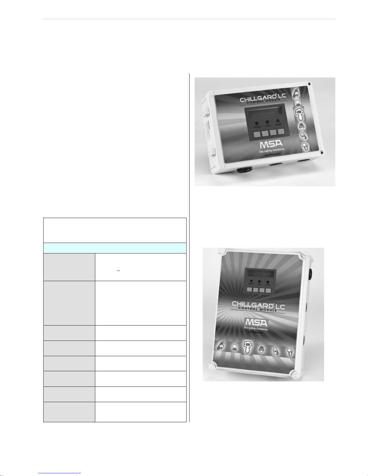
Chillgard® LC
Control Module
Instruction Manual
WARNING
"!
THIS MANUAL MUST BE CAREFULLY READ BY ALL
INDIVIDUALS WHO HAVE OR WILL HA VE THE RESPONSIBILITY
FOR INSTALLING, USING, MAINTAINING OR SERVICING THIS
PRODUCT. Like any piece of complex equipment, this prod uct
will perform as designed only if installed, used and serviced in
accorda nce with t he manufact urer’s in structi ons. OTHE RWISE ,
IT COULD FAIL TO PERFORM AS DESIGNED AND PERSONS
WHO RELY ON THIS PRODUCT FOR THEIR SAFETY COULD
SUST AIN SEVERE PERSONAL INJUR Y O R DEATH.
The warranties made by Mine Safety Appliances Company with respect to this product are
voided i f t he p r odu c t is n ot i nst a lle d , us ed an d s er vi ce d in a cc o rd ance w it h th e ins t ru cti o ns
in this manual. Plea se protec t yourself and others by follow ing them. We encourage our
customers to write or call regarding this equipment prior to use or for any additional
information relative to use or repairs.
MSA North America 1-800-MSA-INST or FAX (724) 776-8783
MSA International (412) 967-3354 or FAX (412) 967-3451
In Cana da 1-800-267-0672 or FAX (416) 663-5908
© Mine Safety Appliances Company 2008 - All Right s Reserved
This manual is available on the internet at www.msanet.com
Manufactured by
MSA NORTH AMERICA
PITTSBURGH, PENNSYLVANIA 15230
(L) REV 4 I MZ001-036 10036865
Page 2

MSA
Permanent Instrument Warranty
1. Warranty- Seller warrants that this product
will be free from mechanical defect or faulty
workmanship for a period of two years
from date of shipment, provided it is
maintained and used in accordance with
Seller’s instructions and/or
recommendations. This warranty does not
apply to expendable or consumable parts
whose normal life expectancy is less than
one (1) year such as, but not limited to,
non-rechargeable batteries, filament units,
filter, lamps, fuses etc. The Seller shall be
released from all obligations under this
warranty in the event repairs or
modifications are made by persons other
than its own or authorized service
personnel or if the warranty claim results
from physical abuse or misuse of the
product. No agent, employee or
representative of the Seller has any
authority to bind the Seller to any
affirmation, representation or warranty
concerning the product. Seller makes no
warranty concerning components or
accessories not manufactured by the
Seller, but will pass on to the Purchaser all
warranties of manufacturers of such
components. THIS WARRANTY IS IN
LIEU OF ALL OTHER WARRANTIES,
EXPRESSED, IM PL IED O R STAT UT ORY,
AND IS STRICTLY LIMITED TO THE
TERMS HEREOF. SELLER
SPECIFICALLY DISCLAIMS ANY
WARRANTY OF MERCHANTABILITY OR
OF FITNESS FOR A PARTICULAR
PURPOSE.
2. Exclusive Remedy- It is expressly agreed
that Purchaser’s sole and exclusive remedy
for breach of the above warranty, for any
tortious conduct of Seller, or for any other
cause of action, shall be the repair and/or
replacement at Seller’s option, of any
equipment or parts thereof, which after
examination by Seller is proven to be
defective. Replacement equipment and/or
parts will be provided at no cost to
Purchaser, F.O.B. Seller’s Plant. Failure of
Seller to successfully repair any
nonconforming product shall not cause the
remedy established hereby to fail of its
essential purpose.
3. Exclusion of Consequential Damage-
Purchaser specifically understands and
agrees that under no circumstances will
seller be liable to purchaser for economic,
special, incidental or consequential
damages or losses of any kind whatsoever,
including but not limited to, loss of
anticipated profits and any other loss
caused by reason of nonoperation of the
goods. This exclusion is applicable to
claims for breach of warranty, tortious
conduct or any other cause of action
against seller.
Page 3

Chillgard LC Control Module General Warnings and Cautions
General Warnings and Cautions
WARNING
"!
1. The Control Module described in this manual
must be installed, operated, and
maintained in strict accordance with the
labels, cautions, warnings, instructions, and
within the limitations stated.
anyone other than authorized MSA service
personnel, could cause the product to fail
to perform as designed, and persons who
rely on this product for their safety could
sustain serious personal injury or death.
2. The Control Module must not be installed in
outdoor areas or in locations where
explosive concentrations of combustible
gases or vapors might occur in the
atmosphere: Class 1, Group A, B, C, and D
areas as defined by the NEC. Because the
Control Module is not explosion-proof, it
must be located in non-hazardous areas.
3. Use only genuine MSA replacement parts
when performing any maintenance
procedures provided in this manual. Failure
to do so may seriously impair instrument
performance. Repair or alteration of the
Chillgard LC System, beyond the scope of
these maintenance instructions or by
Failure to comply with the above warnings can result in serious personal injury or death.
4. The Chillgard LC Control Module must be
installed, located and operated in
accordance to all applicable codes. These
codes include, but are not limited to, the
National Fire Prevention Code and National
Electric Code.
5 Protect the Chillgard LC Control Module from
vibration and heating; otherwise, improper
operation may result, which can result in
personal injury or death.
6. Do not exceed the relay contact ratings listed
in Section 1, TABLE B-1 Otherwise, relay
operation may fail, which can result in
personal injury or death.
Page 4

Chillgard LC Control Module Table of Contents
Table of Contents
Introduction. . . . . . . . . . . . . . . . . . . . . . . . . . . . . . . . . . . . . . . . . . . . . . . . . . . . . . . . . . . . . . . . . . . . . . . 1-1
General Description . . . . . . . . . . . . . . . . . . . . . . . . . . . . . . . . . . . . . . . . . . . . . . . . . . . . . . . . . . . . . 1-1
Table 1-1. Chillgard LC System General Operating Specifications . . . . . . . . . . . . . . . . . . . . . . . . . 1-1
Figure 1-1. Chillgard LC Control Module Standard Version
(24 Volt AC/DC or 110/220 AC Version) . . . . . . . . . . . . . . . . . . . . . . . . . . . . . . . . . . . . . . . . . . 1-1
Figure 1-2. Chillgard LC Control Module With Internal Transformer . . . . . . . . . . . . . . . . . . . . . 1-1
Termi n o l o g y . . . . . . . . . . . . . . . . . . . . . . . . . . . . . . . . . . . . . . . . . . . . . . . . . . . . . . . . . . . . . . . . . . . . . . 1-2
Connection of the Chillgard Instruments Using RS-485 Communications . . . . . . . . . . . . . . . . . . . . . . . 1-3
Multiple Sensor Modules with a Chillgard LC Control Module (Daisy Chain). . . . . . . . . . . . . . . . . . 1-3
Multiple Sensor Modules with a Chillgard LC Control Module (Two Branch). . . . . . . . . . . . . . . . . . 1-3
Figure 1-3. Connection of the Sensor and LC Instruments Using RS-485 Communications . . 1-3
Figure 1-4. Multiple Sensor Modules with a Chillgard LC Control Module (Daisy Chain) . . . . . 1-4
Figure 1-5. Multiple Sensor Modules with a Chillgard LC Control Module (Two Branch) . . . . . 1-4
Section 2
Insta llation and Set-u p . . . . . . . . . . . . . . . . . . . . . . . . . . . . . . . 2 - 1
Recei vi n g . . . . . . . . . . . . . . . . . . . . . . . . . . . . . . . . . . . . . . . . . . . . . . . . . . . . . . . . . . . . . . . . . . . . . . . . 2-1
Unpac ki n g th e S ystem . . . . . . . . . . . . . . . . . . . . . . . . . . . . . . . . . . . . . . . . . . . . . . . . . . . . . . . . . . . . . . 2-1
WARNIN G. . . . . . . . . . . . . . . . . . . . . . . . . . . . . . . . . . . . . . . . . . . . . . . . . . . . . . . . . . . . . . . 2-1
"
Initi a l In sp e c t i o n . . . . . . . . . . . . . . . . . . . . . . . . . . . . . . . . . . . . . . . . . . . . . . . . . . . . . . . . . . . . . . . . 2-1
Location of the Control Module. . . . . . . . . . . . . . . . . . . . . . . . . . . . . . . . . . . . . . . . . . . . . . . . . . . . . . . . 2-1
" WAR N ING. . . . . . . . . . . . . . . . . . . . . . . . . . . . . . . . . . . . . . . . . . . . . . . . . . . . . . . . . . . . . . . 2-1
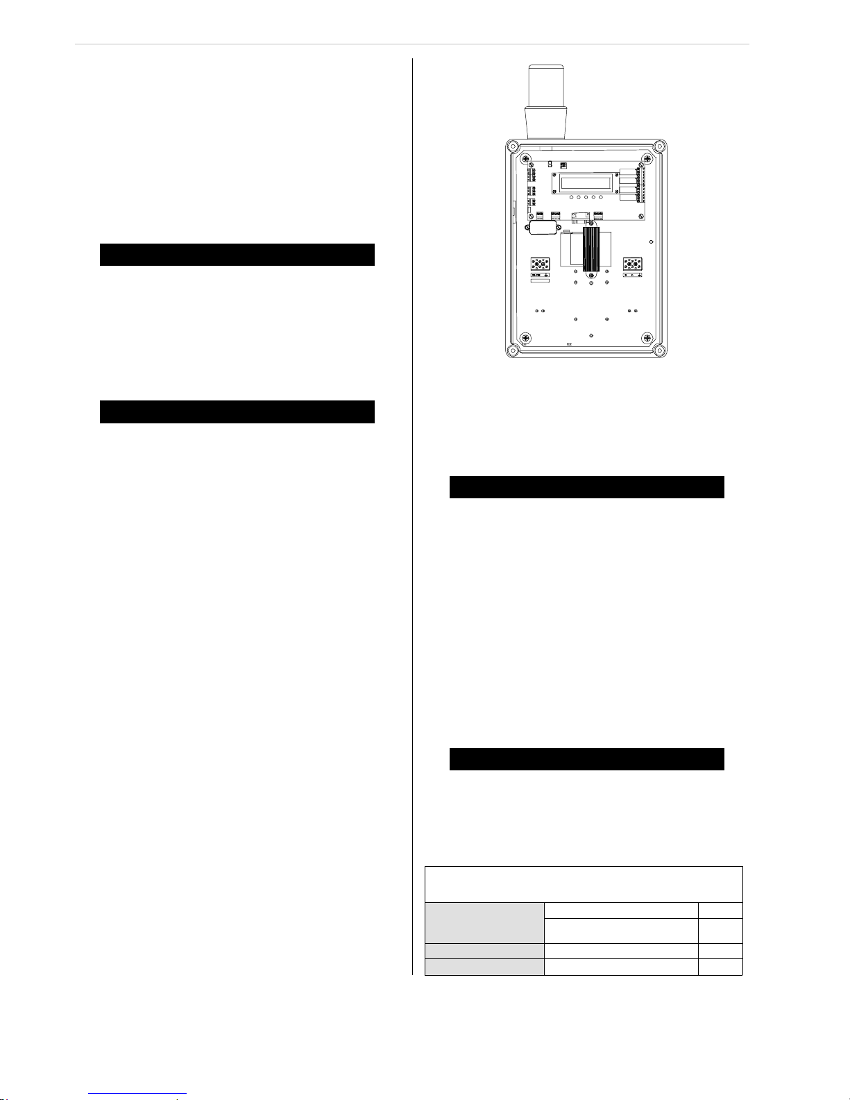
Figure 2-1. Basic LC Control Module with Door Open . . . . . . . . . . . . . . . . . . . . . . . . . . . . . . . 2-1
Wiring Connections. . . . . . . . . . . . . . . . . . . . . . . . . . . . . . . . . . . . . . . . . . . . . . . . . . . . . . . . . . . . . . . . . 2-2
Opening the Unit . . . . . . . . . . . . . . . . . . . . . . . . . . . . . . . . . . . . . . . . . . . . . . . . . . . . . . . . . . . . . . . 2-2
" CA U TION . . . . . . . . . . . . . . . . . . . . . . . . . . . . . . . . . . . . . . . . . . . . . . . . . . . . . . . . . . . . . . . 2-2
Unit Po w e r Wiring. . . . . . . . . . . . . . . . . . . . . . . . . . . . . . . . . . . . . . . . . . . . . . . . . . . . . . . . . . . . . . . 2-2
"!CAUTION . . . . . . . . . . . . . . . . . . . . . . . . . . . . . . . . . . . . . . . . . . . . . . . . . . . . . . . . . . . . . . . 2-2
" WAR N ING. . . . . . . . . . . . . . . . . . . . . . . . . . . . . . . . . . . . . . . . . . . . . . . . . . . . . . . . . . . . . . . 2-2
" CA U TION . . . . . . . . . . . . . . . . . . . . . . . . . . . . . . . . . . . . . . . . . . . . . . . . . . . . . . . . . . . . . . . 2-2
Tabl e 2 -1 . Option S w i tc h Ta b l e. . . . . . . . . . . . . . . . . . . . . . . . . . . . . . . . . . . . . . . . . . . . . . . . . . . . . 2- 2
Figure 2-2. Transformer Version LC Control Module with Door Open . . . . . . . . . . . . . . . . . . . 2-2
Figure 2-3. Standard Version Wiring Diagram . . . . . . . . . . . . . . . . . . . . . . . . . . . . . . . . . . . . . 2-3
Figu re 2-4. Tra n s fo r m e r V e rsion Wiring D i a g ra m . . . . . . . . . . . . . . . . . . . . . . . . . . . . . . . . . . . 2-3
Wirin g to th e Ch i l l g a r d Se n s o r s . . . . . . . . . . . . . . . . . . . . . . . . . . . . . . . . . . . . . . . . . . . . . . . . . . . . 2-4
Addressing . . . . . . . . . . . . . . . . . . . . . . . . . . . . . . . . . . . . . . . . . . . . . . . . . . . . . . . . . . . . . . . . . . . . 2-4
" WAR N ING. . . . . . . . . . . . . . . . . . . . . . . . . . . . . . . . . . . . . . . . . . . . . . . . . . . . . . . . . . . . . . . 2-4
Tabl e 2 -2 . C h i l l g a r d D ip Swi tch Pos i t i o n s. . . . . . . . . . . . . . . . . . . . . . . . . . . . . . . . . . . . . . . . . . . . . 2-4
Figure 2-5. Chillgard LS Sensor Board Connections . . . . . . . . . . . . . . . . . . . . . . . . . . . . . . . . 2-4
Figure 2-6. Chillgard M-100 Jumper Locations . . . . . . . . . . . . . . . . . . . . . . . . . . . . . . . . . . . . 2-5
Analog Signal Output Wiring . . . . . . . . . . . . . . . . . . . . . . . . . . . . . . . . . . . . . . . . . . . . . . . . . . . . . . 2-6
CAUTION. . . . . . . . . . . . . . . . . . . . . . . . . . . . . . . . . . . . . . . . . . . . . . . . . . . . . . . . . . . . . . . . 2-6
"!
Page 5

Table of Contents Chillgard LC Control Module
Relay Ou t p u ts. . . . . . . . . . . . . . . . . . . . . . . . . . . . . . . . . . . . . . . . . . . . . . . . . . . . . . . . . . . . . . . . . . 2-6
CAUTION. . . . . . . . . . . . . . . . . . . . . . . . . . . . . . . . . . . . . . . . . . . . . . . . . . . . . . . . . . . . . . . . 2- 7
"
Start-Up. . . . . . . . . . . . . . . . . . . . . . . . . . . . . . . . . . . . . . . . . . . . . . . . . . . . . . . . . . . . . . . . . . . . . . . . . . 2-7
Setup Date, Time, and Logging. . . . . . . . . . . . . . . . . . . . . . . . . . . . . . . . . . . . . . . . . . . . . . . . . . . . . . . . 2-7
CAUTION . . . . . . . . . . . . . . . . . . . . . . . . . . . . . . . . . . . . . . . . . . . . . . . . . . . . . . . . . . . . . . . 2- 7
"
Initi a l Cal i b ration . . . . . . . . . . . . . . . . . . . . . . . . . . . . . . . . . . . . . . . . . . . . . . . . . . . . . . . . . . . . . . . . . . . 2-7
WARNIN G . . . . . . . . . . . . . . . . . . . . . . . . . . . . . . . . . . . . . . . . . . . . . . . . . . . . . . . . . . . . . . . 2-7
"
Section 3
Displa y Sc reens. . . . . . . . . . . . . . . . . . . . . . . . . . . . . . . . . . . . . 3-1
Figure 3-1. Display Screen Overview . . . . . . . . . . . . . . . . . . . . . . . . . . . . . . . . . . . . . . . . . . . . 3-2
Figure 3-2. Start-up and Normal Operation Screens . . . . . . . . . . . . . . . . . . . . . . . . . . . . . . . . . 3-3
Figure 3-3 Set-up Screens. . . . . . . . . . . . . . . . . . . . . . . . . . . . . . . . . . . . . . . . . . . . . . . . . . . . . 3-3
Figure 3-4 Span Calibration Screens. . . . . . . . . . . . . . . . . . . . . . . . . . . . . . . . . . . . . . . . . . . . . 3-4
Figu re 3-5 Zero C a li b r a ti o n . . . . . . . . . . . . . . . . . . . . . . . . . . . . . . . . . . . . . . . . . . . . . . . . . . . . 3- 4
Figu re 3-6 Cali b ra t i o n Ch e ck . . . . . . . . . . . . . . . . . . . . . . . . . . . . . . . . . . . . . . . . . . . . . . . . . . . 3-5
Figure 3-7 Diagnostics Menu . . . . . . . . . . . . . . . . . . . . . . . . . . . . . . . . . . . . . . . . . . . . . . . . . . . 3-5
Figure 3-8 Data Screens . . . . . . . . . . . . . . . . . . . . . . . . . . . . . . . . . . . . . . . . . . . . . . . . . . . . . . 3- 6
Figu re 3-9 Alar m L e ve l Sc re e n. . . . . . . . . . . . . . . . . . . . . . . . . . . . . . . . . . . . . . . . . . . . . . . . . . 3-6
Figu re 3-10 Set u p Al a r m L a tching . . . . . . . . . . . . . . . . . . . . . . . . . . . . . . . . . . . . . . . . . . . . . . . 3-7
Figu re 3-11 Set u p Al a r m R e l a ys . . . . . . . . . . . . . . . . . . . . . . . . . . . . . . . . . . . . . . . . . . . . . . . . 3-7
Figu re 3-12 Audi o A l a rm Scree n . . . . . . . . . . . . . . . . . . . . . . . . . . . . . . . . . . . . . . . . . . . . . . . . 3-8
Figure 3-13 Analog Outputs and Password . . . . . . . . . . . . . . . . . . . . . . . . . . . . . . . . . . . . . . . . 3-8
Figu re 3-14 Set u p Ti mes . . . . . . . . . . . . . . . . . . . . . . . . . . . . . . . . . . . . . . . . . . . . . . . . . . . . . . 3-9
Figure 3-15 Setup Logging. . . . . . . . . . . . . . . . . . . . . . . . . . . . . . . . . . . . . . . . . . . . . . . . . . . . . 3- 9
Figu re 3-16 Revi e w L o g. . . . . . . . . . . . . . . . . . . . . . . . . . . . . . . . . . . . . . . . . . . . . . . . . . . . . . 3-10
Section 4
Mainte na nce. . . . . . . . . . . . . . . . . . . . . . . . . . . . . . . . . . . . . . . . 4-1
General Maintenance . . . . . . . . . . . . . . . . . . . . . . . . . . . . . . . . . . . . . . . . . . . . . . . . . . . . . . . . . . . . . . . 4-1
Obtai n i n g R e p l a ce m e n t P a rts. . . . . . . . . . . . . . . . . . . . . . . . . . . . . . . . . . . . . . . . . . . . . . . . . . . . . . . . . 4-1
"!WARNING. . . . . . . . . . . . . . . . . . . . . . . . . . . . . . . . . . . . . . . . . . . . . . . . . . . . . . . . . . . . . . . 4-1
Tabl e 4 -1 . R e p l a c e ment Pa rt s. . . . . . . . . . . . . . . . . . . . . . . . . . . . . . . . . . . . . . . . . . . . . . . . . . . . . . 4-1
" WAR N ING. . . . . . . . . . . . . . . . . . . . . . . . . . . . . . . . . . . . . . . . . . . . . . . . . . . . . . . . . . . . . . . 4- 1
Table 4-2. Troubleshooting Guidelines . . . . . . . . . . . . . . . . . . . . . . . . . . . . . . . . . . . . . . . . . . . . . . . 4-2
Section 5
Data L oggi ng. . . . . . . . . . . . . . . . . . . . . . . . . . . . . . . . . . . . . . . 5-1
Numbe r of Data Poi n ts Used. . . . . . . . . . . . . . . . . . . . . . . . . . . . . . . . . . . . . . . . . . . . . . . . . . . . . . . . . . 5-1
User Se t u p Op ti o n s. . . . . . . . . . . . . . . . . . . . . . . . . . . . . . . . . . . . . . . . . . . . . . . . . . . . . . . . . . . . . . . . . 5-1
Viewing Alarms/Events and Data . . . . . . . . . . . . . . . . . . . . . . . . . . . . . . . . . . . . . . . . . . . . . . . . . . . . . . 5-1
Figure 5-1. Log Description . . . . . . . . . . . . . . . . . . . . . . . . . . . . . . . . . . . . . . . . . . . . . . . . . . . . 5-1
Section 6
Calibr a t i o n . . . . . . . . . . . . . . . . . . . . . . . . . . . . . . . . . . . . . . . . . 6-1
Diffu si o n V e rs i o n C a l ib r a t i o n. . . . . . . . . . . . . . . . . . . . . . . . . . . . . . . . . . . . . . . . . . . . . . . . . . . . . . . . . . 6-1
Calib r a t i o n Equ i p ment - (FIGUR E 6 - 1 ). . . . . . . . . . . . . . . . . . . . . . . . . . . . . . . . . . . . . . . . . . . . . . . 6-1
"!WARNING. . . . . . . . . . . . . . . . . . . . . . . . . . . . . . . . . . . . . . . . . . . . . . . . . . . . . . . . . . . . . . . 6-1
Page 6

Chillgard LC Control Module Table of Contents
Initial Calibration Procedures . . . . . . . . . . . . . . . . . . . . . . . . . . . . . . . . . . . . . . . . . . . . . . . . . . . . . . 6-1
Figu re 6-1. Cal i b ra ti o n E q u i p ment . . . . . . . . . . . . . . . . . . . . . . . . . . . . . . . . . . . . . . . . . . . . . . 6-1
" CA U TION . . . . . . . . . . . . . . . . . . . . . . . . . . . . . . . . . . . . . . . . . . . . . . . . . . . . . . . . . . . . . . . 6-2
" CA U TION . . . . . . . . . . . . . . . . . . . . . . . . . . . . . . . . . . . . . . . . . . . . . . . . . . . . . . . . . . . . . . . 6-2
Calib r a t i o n Gu i d e l i n e s . . . . . . . . . . . . . . . . . . . . . . . . . . . . . . . . . . . . . . . . . . . . . . . . . . . . . . . . . . . 6-2
Calibration Check Procedure . . . . . . . . . . . . . . . . . . . . . . . . . . . . . . . . . . . . . . . . . . . . . . . . . . . . . . 6-2
"!WARNING. . . . . . . . . . . . . . . . . . . . . . . . . . . . . . . . . . . . . . . . . . . . . . . . . . . . . . . . . . . . . . . 6-2
Figure 6-2. Applying Calibration Gas to the Chillgard LS Refrigerant Monitor. . . . . . . . . . . . . . 6-2
" CA U TION . . . . . . . . . . . . . . . . . . . . . . . . . . . . . . . . . . . . . . . . . . . . . . . . . . . . . . . . . . . . . . . 6-3
Single or Four-Point Pumped Version Calibration . . . . . . . . . . . . . . . . . . . . . . . . . . . . . . . . . . . . . . . . . 6-3
Introduction. . . . . . . . . . . . . . . . . . . . . . . . . . . . . . . . . . . . . . . . . . . . . . . . . . . . . . . . . . . . . . . . . . . . 6-3
Calib r a t i o n Equ i p ment . . . . . . . . . . . . . . . . . . . . . . . . . . . . . . . . . . . . . . . . . . . . . . . . . . . . . . . . . . . 6-3
" CA U TION . . . . . . . . . . . . . . . . . . . . . . . . . . . . . . . . . . . . . . . . . . . . . . . . . . . . . . . . . . . . . . . 6-3
Tabl e 6 -1 . R P C a l i b ra ti o n G a s e s . . . . . . . . . . . . . . . . . . . . . . . . . . . . . . . . . . . . . . . . . . . . . . . . . . . 6-3
" WAR N ING. . . . . . . . . . . . . . . . . . . . . . . . . . . . . . . . . . . . . . . . . . . . . . . . . . . . . . . . . . . . . . . 6-3
Calibration Procedures. . . . . . . . . . . . . . . . . . . . . . . . . . . . . . . . . . . . . . . . . . . . . . . . . . . . . . . . . . . 6-3
" CA U TION . . . . . . . . . . . . . . . . . . . . . . . . . . . . . . . . . . . . . . . . . . . . . . . . . . . . . . . . . . . . . . . 6-4
" CA U TION . . . . . . . . . . . . . . . . . . . . . . . . . . . . . . . . . . . . . . . . . . . . . . . . . . . . . . . . . . . . . . . 6-4
Calib r a t i o n Gu i d e l i n e s . . . . . . . . . . . . . . . . . . . . . . . . . . . . . . . . . . . . . . . . . . . . . . . . . . . . . . . . . . . 6-4
Figure 6-3. Kit Components . . . . . . . . . . . . . . . . . . . . . . . . . . . . . . . . . . . . . . . . . . . . . . . . . . . 6-4
Figure 6-4. Using Zero Scrubber for Zero Calibration . . . . . . . . . . . . . . . . . . . . . . . . . . . . . . . . 6-5
Figure 6-5. Using Zero Gas Cylinder for Zero Calibration . . . . . . . . . . . . . . . . . . . . . . . . . . . . . 6-5
Calibration Check Procedure . . . . . . . . . . . . . . . . . . . . . . . . . . . . . . . . . . . . . . . . . . . . . . . . . . . . . . 6-6
" WAR N ING. . . . . . . . . . . . . . . . . . . . . . . . . . . . . . . . . . . . . . . . . . . . . . . . . . . . . . . . . . . . . . . 6-6
" CA U TION . . . . . . . . . . . . . . . . . . . . . . . . . . . . . . . . . . . . . . . . . . . . . . . . . . . . . . . . . . . . . . . 6-6
Figure 6-6. Span Calibration . . . . . . . . . . . . . . . . . . . . . . . . . . . . . . . . . . . . . . . . . . . . . . . . . . . 6-6
" CAU T ION. . . . . . . . . . . . . . . . . . . . . . . . . . . . . . . . . . . . . . . . . . . . . . . . . . . . . . . . . . . . . . . 6-7
Appendix A
RS-232 Output . . . . . . . . . . . . . . . . . . . . . . . . . . . . . . . . . . . . . . A-1
Introduction. . . . . . . . . . . . . . . . . . . . . . . . . . . . . . . . . . . . . . . . . . . . . . . . . . . . . . . . . . . . . . . . . . . . . . . A- 1
RS-232 Output . . . . . . . . . . . . . . . . . . . . . . . . . . . . . . . . . . . . . . . . . . . . . . . . . . . . . . . . . . . . . . . . . A-1
Table A-1. RS-232 Parameters. . . . . . . . . . . . . . . . . . . . . . . . . . . . . . . . . . . . . . . . . . . . . . . . . . . . . A-1
Table A-2. Information Structure (Chillgard LC Control Module) . . . . . . . . . . . . . . . . . . . . . . . . . . . A-1
Tabl e A- 3 . Da t a St ru c t u r e. . . . . . . . . . . . . . . . . . . . . . . . . . . . . . . . . . . . . . . . . . . . . . . . . . . . . . . . . A-2
Tabl e A- 4 . Ala rm Stru c tu re . . . . . . . . . . . . . . . . . . . . . . . . . . . . . . . . . . . . . . . . . . . . . . . . . . . . . . . . A-2
Table A-5. Alarms and Events . . . . . . . . . . . . . . . . . . . . . . . . . . . . . . . . . . . . . . . . . . . . . . . . . . . . . A-2
Appendix B
Insta llation Ou t line Dra w ing. . . . . . . . . . . . . . . . . . . . . . . . . . . B-1
Figure B-1. Installation Outline Drawing for Standard Version . . . . . . . . . . . . . . . . . . . . . . . . . B-2
Figu re B -2 . In stall a t i o n Ou tl i n e D ra w i n g fo r T r a n sformer Versi o n. . . . . . . . . . . . . . . . . . . . . . . B-3
Page 7
Chillgard LC Control Module Section 1, General Information
Section 1
General Information
Introduction
General Description
The Chillgard LC unit is a control module which
can communicate with up to eight Chillgard LS
or twelve Chillgard M100 Refrigerant Sens ors.
The Chillgard LC Control Module can be
installed remotely from the sensors, thus
enabling remote control of that Chillgard LS or
the Chillgard M100 Sensor.
The Chillgard LC comes in two major versions
based upon the power supply in the unit:
• 24 Volt AC/DC or 110/220 VAC version
• Internal Transformer version - 120 Volt input,
24 VAC output for powering Remote Sensor
Modules.
See FIGURES 1-1 and 1-2 to identify your unit.
Table 1-1. Chillgard LC System
General Operating Specifications
OPERATING SPECIF ICATIONS
100 to 240 VAC, 50-60 Hz, 25 W
VOLTAGE RATING
POWER
REQUIREMENTS
TROUBLE RELAY
ALARM 1 RELAY
ALARM 2 RELAY
ALARM 3 RELAY
24 VDC +10% -0%
24 VAC
Transforme r Version: 120 V, 60 Hz, 75 VA
.15 am ps at 120 VAC;
.10 am ps at 240 VAC
0.6 am ps at 24 VAC
0.1 am ps at 24 VDC
Minimum wire size: #18 AWG
The LC Controller can power the
Chillgar d LS and seve n Chillgard
M-100 s ensors
Normally energized, Form C contact:
240 VAC, 5 amp resistive SPDT
One relay, Form C contacts: 240
VAC, 5 amps resistive SPDT
One relay, Form C contacts: 240
VAC, 5 amps resistive SPDT
One relay, Form C contacts: 240
VAC, 5 amps resistive SPDT
+10%
Figure 1-1. Chillgard LC Control Module
Standard Version
(24 Volt AC/DC or 110/220 AC Version)
ANALOG OUTPUTS
MAXIMUM OUTPUT
SIGNAL LOAD FOR
4-20 mA OUTPUT
4 to 20 mA sourcing, 500 ohm load ,
0-6 VDC, 2 K ohm load
600 ohms (includes wiring)
Figure 1-2. Chillgard LC Control Module
With Internal Transformer
1-1
Page 8
Section 1, General Information Chillgard LC Control Module
Table 1-1. Chillgard LC System
General Operating Specifications
OPERATING SPECIF ICATIONS
AUDIO ALARM
DRIVE OUTPUT
OPERATING
TEMPERATURE
STANDARD
VERSION
DIMENSIONS
STANDARD
VERSION WEIGHT
TRANSFORMER
VERSION
DIMENSIONS
TRANSFORMER
VERSION WEIGHT
TRANSPORT AND STORAGE CONDITIONS
TEMPERATURE -40
HUMIDITY 99% RH non-condensing
POLLUTION
DEGREE AND
INSTALLATION
CATEGORY
24 VDC 50-ohm load maximum
(availa ble only with non-beacon
models)
o
0 to 40
C (32 to 104oF)
7.5" high, 12.5" wide, 3.5" deep
19.05 cm high, 31.75 cm wide,
8.89 cm deep
3.5 pounds (1.59 kilograms)
14.7" high, 11.2" wid e, 5" deep
373 mm high, 284 mm wide,
127 mm deep
8.4 pounds (3.82 kilograms)
o
C to +60oC (-40oF to 140oF)
2
ZEROING- The process of placing a zero gas on
the unit during calibration.
SPAN- Full-scale or up-scale reading on
meter display.
SPANNING- The process of placing a full-scale or
span gas on the unit during calibrati on.
SPAN GAS VALUE- The gas concentration that
gives the instrument a full-scale or up-scale value.
This value is printed on the calibration gas
cylinder containing the gas.
FLOW RATE- Volume of gas drawn through the
sample line per minute.
EXHAUST GAS- Sample gas after it passes
through the sensor.
PUMP- The electric motor driven dev ice that
moves the gas sample to the refriger ant monitor.
ALARMS- The Chillgard LC System has three
alarms to alert the user at specific,
user-adjustable refrigerant gas concentrat ions.
(Level 1 = Caution, Level 2 = Warning and Level
3 = Alarm.)
RELATIVE HUMIDITY- The percent of water vapor
saturation in air at a given t emperature.
POINT NUMBER- The location or ar ea from which
a gas sample is drawn. Up to four , eight, or 12
areas, sequentially numbered from 1 to 12, can
be sampled.
Terminology
Become familiar with the following terminology.
ZERO- A zero (0) indication on the meter
display usually indicates fresh air ( no refrigerant
gas present).
FRESH AIR- Air that has no possibility of
containing refrigerant gas.
TEMPERATURE EFFECT- The gas response
displayed by the instrument (PPM) can change
+3 ppm for each degree (C) that the instrument is
operating above/below the temperature at which
the instrument was last calibrated.
1-2
Page 9

Chillgard LC Control Module Section 1, General Information
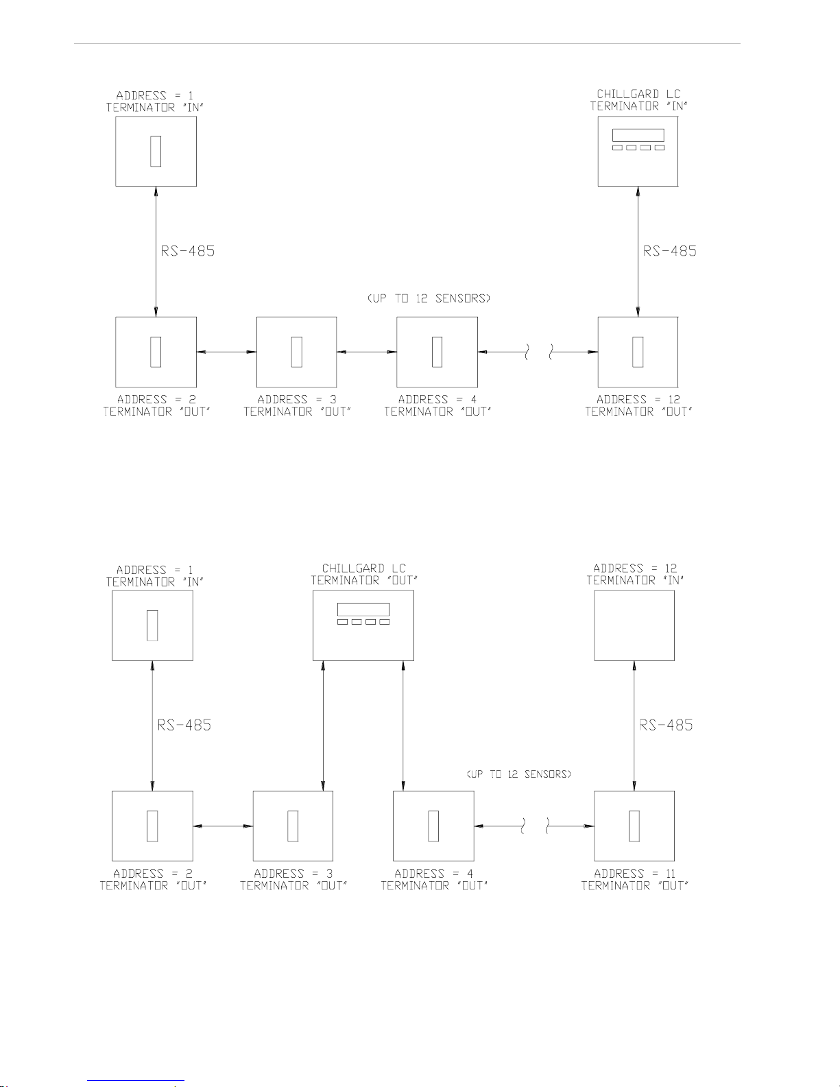
Connection of the Chillgard
Instruments Using RS-485
Communications
The Chillgard LC instrument acts as t he Master
device in the network. The LC inst rument initiates
and controls all communications on the network.
The LC instrument sends out commands and
requests for data from individual sens ors. When
the instruments are powered up, the LC unit
automatically detects the number and gas type of
all instruments on the network.
In a simple system using a single sens or module
and an LC Control module, the two m odules are
connected together; both units hav e the RS-485
terminators "IN" (FIGURE 1-3). Ref er to Section
2, Installation and Setup, for s etting the address
switches and FIGURES 2-2 and 2-3 f or the
location of the termination jumpers.
NOTE:Each sensor must have a different address.
The total length of the RS-485 cable cannot
exceed 1000 feet (304 meters).
MSA recommends Belden #9841
low-capacitance cable.
Multiple Sensor Modules with a
Chillgard LC Contro l Mo du le
(Daisy Chain)
See FIGURE 1-4.
NOTE:Up to eight Chillgard LS Sensors can be
connected to a Chillgard LC Controller.
(They must be addressed as Points 1
through 8.)
• LS1 devices can be on points 1 through 8.
• LS4 devices must be on point 1 and/or 5
and will also use the next three physical
addresses.
• LS4 on point 1 takes addresses 1, 2, 3, and 4.
• LS4 on point 5 takes addresses 5, 6, 7, and 8.
• LS4 cannot be on addresses 9, 10, 11, or 12.
Multiple Sensor Modules with a
Chillgard LC Contro l Mo du le
(Two Branch)
See FIGURE 1-5. Each end of the net work must
have the terminator IN; modules in t he middle
must have terminators OUT. RS-485 connec tions
from the Chillgard LC Control unit mus t have no
more than two terminations.
Figure 1-3. Connection of the Sensor and LC
Instruments Using RS-485 Communications
1-3
Page 10
Section 1, General Information Chillgard LC Control Module
Figure 1-4. Multiple Sensor Modules
with a Chillgard LC Control Module (Daisy Chain)
with a Chillgard LC Control Module (Two Branch)
1-4
Figure 1-5. Multiple Sensor Modules
Page 11
Chillgard LC Control Module Section 2, Installation and Set-Up
Section 2
Installation and Set-up
Receiving
Unpacking the System
To unpack the equipment:
1. Carefully remove the Chillgard LC Control
Module from its shipping container(s) in
order to prevent damage to sensitive
electrical components. If any damage is
found, report it to the shipper immediately.
WARNING
"
Do not install or operate a damaged unit. It
may not function properly and may not alert
you to any gas conditions.
2. Search through all packing material and
containers to avoid inadvertently discarding
usable or valuable parts. Report any
shortages immediately to MSA.
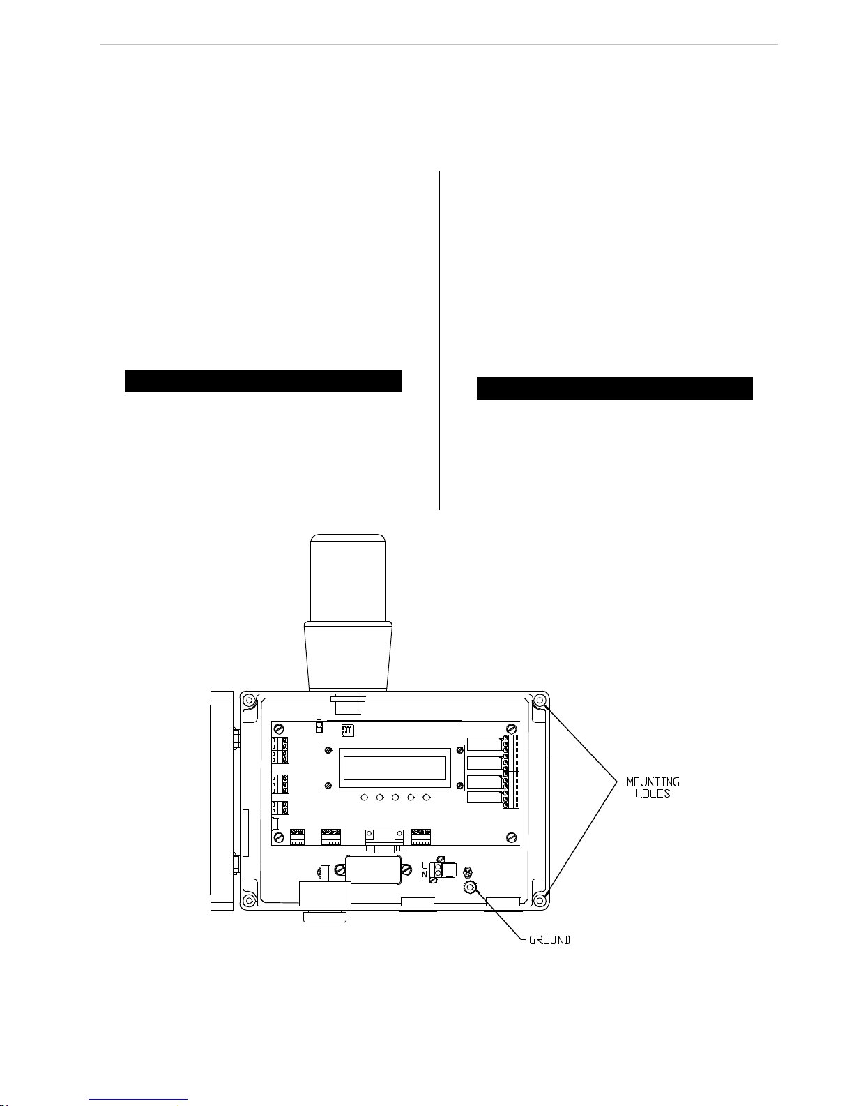
Initial Inspection
With the front door open, carefully inspect
components and assemblies inside the enclosure.
If damage or shortage is evident , advise and
promptly file the proper claim with t he carrier.
Location of the Control
Module
WARNING
"
Explosion Hazard!
Unit must not be located in areas that may
contain a flammable mixture of gas and air;
failure to follow this requirement can result
in death, serious injury, or equipment or
property damage.
Figure 2-1. Basic LC Control Module with Door Open
2-1
Page 12
Section 2, Installation and Set-Up Chillgard LC Control Module
Wiring Connections
Opening the Uni t
All wiring to the Chillgard LC unit is made via the
bottom entries. Open the unit to provide complete
access to all wiring connections.
Ensure that all wiring codes are followed. These
codes include, but are not limited t o, the National
Electrical Code.
CAUTION
"
Component Damage!
Monitor components must be protected from
splashing, spraying, or dripping water.
Failure to do so may cause damage to
internal components.
Unit Power W ir ing
!CAUTION
"
Instr ument Damage!
Correct powe r voltage mus t be connected to
the instrument. Failure to use cor rect voltage
may res ult in instrume nt damage.
A separate, dedicated power sourc e is
recommended for the refrigerant contr ol module to
ensure that the unit remains power ed when other
circuits are shut down for s ervicing, routine
maintenance or shift changes. Supply ear thground
is installed on lug first and all com ponent
earthgrounds are connected afterwards .
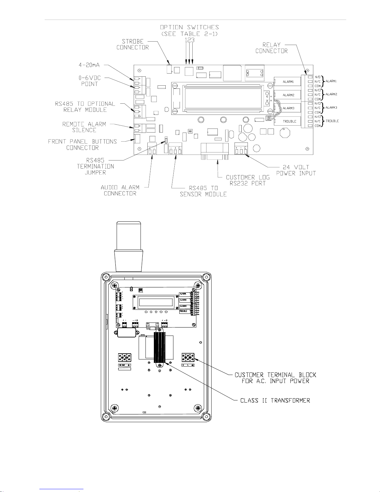
Standard Version
The control module uses a wide range power
supply which can accept AC power f rom 100 to
240 volts, 50 or 60 Hz. I f 24 Volt AC or DC is
available, power can be supplied directly to the
control board (FIGURE 2-3). The 24 V olt power
source used with this equipment must be
separated from mains by double or reinforc ed
insulation. If the 110/220 Volt power opt ion is
available, power can be supplied to terminal block
as shown in FIGURE 2-1.
Transformer Version
If the Chillgard LC unit contains t he internal
transformer, supply power as shown in
FIGURE 2-4. The resulting 24 VAC output from
the transformer can be used to power up to five
diffusion LS units or two pumped f our-point LS
units. However, voltage drop will occ ur over
extended line lengths with multiple sensors.
Ensure minimum required voltage is present at
the sensor terminals for each sensor module.
Figure 2-2. Transformer Version LC Control Module
with Door Open
WARNING
"
If insufficient voltage is supplied, unit could
display incorrect readings. check each
sensor module for minimum required voltage
at each unit.
With 18 AWG wire, a Chillgard LS Sensor Module
can be located a maximum distance of 450 feet
from the Chillgard LC Control Module. Two
Chillgard LS four-point Sensor Modules
daisy-chained from the Chillgard LC Contr ol
Module can be connected a maximum of 150 f eet
from the Chillgard LC Control Module. Wit h 18
AWG wire, seven Chillgard M-100 sensors can be
daisy-chained from the LC Control Module to a
distance of 1500 feet.
CAUTION
"
If the Chillgard LC transformer or other AC
power is used to power the Chillgard M-100
Sensor, the Chillgard M-100 AC power must
be isolated from the LC power for proper
operation.
Table 2-1. Option Switch Table
SWITCH 1
CUSTOMER RS232
PORT SPEED SET
SWITCH 2 N/A
SWITCH 3 N/A
19,200 BPS 8, N, 1 UP
9,600 BPS 8, N, 1 DN
2-2
Page 13
Chillgard LC Control Module Section 2, Installation and Set-Up
Figure 2-3. Standard Version Wiring Diagram
Figure 2-4. Transformer Version Wiring Diagram
2-3
Page 14

Section 2, Installation and Set-Up Chillgard LC Control Module
Wiring to t he Chil lgard Sens ors
The Chillgard LC Control Module can
communicate to up to 12 sample points.
Communication between these devices is
achieved through RS-485 modbus protocol
[see the Chillgard LS Instruc tion Manual
(P/N 10035164) and/or the Chillgard M-100
Instruction Sheet (P/N 10073591) for definition of
protocol]. This protocol allows for dais y-chaining
of the sensor modules to the c ontrol module. See
FIGURE 2-3 for wiring to the control m odule.
Addressing
Each sensor module must have a dist inct
address. The sensor module address swit ch is
used to specify the addresses of each sensor
module (FIGURE 2-5 and 2-6). The addresses
also determine the point number on the dis play.
WARNING
"
If the addresses of each sensor module are
not unique to each unit, the control modul e
may not recognize one or more of the sensor
modules.
The dip switch positions are shown in TABLE 2-2.
Table 2-2. Chillgard LS Dip Switch Positions
POINT ID
1100 0 0 0 -2101 1 0 0 -3102 0 1 0 -4103 1 1 0 -5104 0 0 1 -6105 1 0 1 -7106 0 1 1 -8107 1 1 1 --
1234
NOTE: 1 indicate s closed.
DIP SWITCH
For four-point sensor modules, there ar e two valid
dip switch settings: 100 and 104.
• If dip switch setting 100 is chosen, addresses
101 to 103 will be assigned to the four-point
unit and will not be available for use on other
units.
Figure 2-5. Chillgard LS Sensor Board Connections
2-4
Page 15

Chillgard LC Control Module Section 2, Installation and Set-Up
Figure 2-6. Chillgard M-100 Jumper Locations
2-5
Page 16

Section 2, Installation and Set-Up Chillgard LC Control Module
• If dip switch setting 104 is chosen, addresses
105 to 107 will be assigned to the four-point
unit and will not be available for use on other
units.
Analog Signal Output Wi r i ng
The unit has two availa ble analog outputs. The
4 to 20 mA analog output is software-se lectable
between 10% or 100% of full scale:
• 4-20 mA, isolated, current sourcing
• 0-6 VDC outputs, 0.5-Volt steps to indicate
point being monitored. For example, 1.5 V
represents point 3 at the milliamp output.
Analog output wiring should enter the unit through
the hole provided on the left side of the unit. The
maximum wire size that these connectors can
accept is Listed #12 AWG; t he maximum cable
length is 500 feet (166 meters) .
It is suggested that Listed #18 AWG, twisted-pair
wire be used. If shielded wire is nec essary,
ground the shields of all cables at t he receiving
end of the signal. Do not ground or connect the
shields at the Chillgard LC Control Module. See
FIGURE 2-2 for connecting the analog outputs.
CAUTION
"!
Bundle low voltage wiring together (lower than
30 volts), separate from high voltage wiring
(higher than 30 volts).
Optional Alarm Beacon
Your unit may have an optional alarm kit installed.
This kit is made up of a beac on on the top of the
unit. It is factory-wired so no additional wiring is
necessary; it lights when an Alar m 3 indication is
given by the instrument. Connection is made to
the strobe connector (FIGURE 2- 2). IP rating
shown on the strobe light applies t o the
strobe only.
Rela y Outputs
Alarm Relays
There are three alarm relay outputs:
• Alarm 1 (factory-set to trip at 50 ppm)
• Alarm 2 (factory-set to trip at 150 ppm)
• Alarm 3 (factory-set to trip at 1000 ppm;
300 ppm for R 123)
Each relay can be set up as latching/non-latching
and/or normally-energized/normally de-energized.
Contacts are Form C at 240 V olts AC 5 amps
resistive. User can adjust alarm trip points via the
front pane l (see Secti on 3, FIGURE 3-11).
Alarm Relay Connections Wiring
Three refrigerant level alarm relay out puts are
provided. All alarm relays are Form C, SPDT
relays which can be wired to either closed or
opened contacts in an alarm condition. Use copper
conductors only.
Each relay has contacts for:
• NORMALLY OPEN (NO)
• COMMON (COM)
• NORMALLY CLOSED (NC)
The function of each relay connec tor terminal is
indicated on FIGURE 2-2.
NOTE:The maximum wire size that these
connectors can accept is #12 AWG.
Fault Relay
There is one relay (the Fault r elay) within the unit
that indicates that a trouble or start-up condition
exists. This relay is configured from the factory
and operates differently than the alarm relays. It
operates in a normally-energized mode.
This relay is energ ized when the instrument is:
• normally operating,
• in the calibration mode, or
• in the setup condition.
The relay is de-energized when:
• a fault is detected,
• the unit is in the start-up state, or
• the main power is lost.
This means that power is no longer prov ided to
the relay coil. It is not pos sible to change the
configuration of the Trouble relay.
The relay connector function or ident ification:
• NORMALLY OPEN (NO),
• COMMON (COM),
• NORMALLY CLOSED (NC)
as marked in FIGURE 2-2 refers to the relay
contacts as if the relay is de-energized or in the
trouble condition. A relay contact is provided
between the Normally Closed (NC) and Common
(COM) position. This contact will be made in t he
event that main power to the unit is lost or any
other trouble condition exists.
2-6
Page 17

Chillgard LC Control Module Section 2, Installation and Set-Up
Remote Alarm Silence Switch
The audible alar m and latched ref rigerant level
alarms can be remotely reset throug h a switch t hat
has a momentary c ontact opening (normally clo sed
set of contac ts). Connections are made as shown in
FIGURE 2-3 with t he wiring entering the enclosure
through the hole on t he left side of the instrument.
The switch must have signal-level contacts , typically
gold plated. Th e maximum distan ce from the reset
switch to the co ntrol module, using 18 AWG wire, is
250 feet. The maximum wire size that these
connectors can accept is #12 AWG.
Audible Alarm Output
An outpu t is provided to drive the horn on the
bottom of the uni t (FIGURE 2-2).
CAUTION
"
All field wiring must be done in accordance
with national and local electrical codes.
Start-Up
The following steps outline the procedures t o
power-ON the Chillgard LC Control Module:
1. Before applying power to the unit, verify
proper power will be applied to the unit.
2. Turn the instrument ON at the circuit breaker
or fuse that supplies power to the
instrument. (The instrument does not have
a power switch.)
• A green LED indicates that power is ON
and communication is established to a
sensor module.
NOTE:The display will begin to indicate the gas
concentration of each point connected to the
Chillgard LC Control Module.
After power-ON, allow for unit s tabilization
(about 30 minutes) before checking calibration
of instrument.
Setup Date, Time, and
Logging
The data log on the LC unit must be
initialized by setting the date and time under the
Setup - Setup Time and Date Menu.
Setup logging next on the following menu:
1. Turn ON logging.
2. Set the log frequency.
3. Clear the log file to reset any readings.
4. Reset the LC unit to re-initialize the log to a
clean start.
" CAUTION
If this is not done, data recorded will not
have a time stamp and data review will not
be possible.
Initial Calibration
WARNING
"
Calibrate after installation; otherwise, false
or erroneous readings can result.
See Chillgard LS Instruction Manual
(P/N 10035164) for calibration or c alibration check
instructions. See Chillgard M100 Instruc tion Sheet
(P/N 10073591) for calibration or c alibration check
instructions.
2-7
Page 18

Chillgard LC Control Module Section 3, Display Screens
Section 3
Display Screens
All instrument operation is performed via the front
panel which consists of four keys and a two-line
by 20-character LCD display. There is no reason
to open the unit for set-up, calibration or
diagnostic testing of the instr ument. The most
commonly used, self-explanatory screens appear
on the following pages. Simply follow the
on-screen menus. The step-by step approac h
guides you through each operation.
• The Display Screen Overview (FIGURE 3-1)
shows a general system function flow. See
the following FIGURES for specific Display
Screen details:
• Start-up and Normal Operation Screens
(FIGURE 3-2)
• Calibration Screens
(FIGURES 3-4 through 3-5)
• Information Screens
(FIGURES 3-7 through 3-8 and
FIGURE 3-16)
• Set-up Screens
(FIGURES 3-3 and 3-10 through 3-15).
3-1
Page 19

Section 3, Display Screens Chillgard LC Control Module
3-2
Figure 3-1. Display Screen Overview
Page 20

Chillgard LC Control Module Section 3, Display Screens
Figure 3-2.
Start-up and Normal Operation Screens
Figure 3-3.
Set-up Screens
3-3
Page 21

Section 3, Display Screens Chillgard LC Control Module
Figure 3-4.
Span Calibration Screens
3-4
Figure 3-5.
Zero Calibration
Page 22

Chillgard LC Control Module Section 3, Display Screens
Figure 3-6.
Calibration Check
Figure 3-7.
Diagnostics Menu
3-5
Page 23

Section 3, Display Screens Chillgard LC Control Module
Figure 3-8.
Data Screens
Figure 3-9.
Alarm Level Screen
3-6
Page 24

Chillgard LC Control Module Section 3, Display Screens
Figure 3-10.
Setup Alarm Latching
Figure 3-11.
Setup Alarm Relays
3-7
Page 25

Section 3, Display Screens Chillgard LC Control Module
Figure 3-12.
Audio Alarm Screen
3-8
Figure 3-13.
Analog Outputs and Password
Page 26

Chillgard LC Control Module Section 3, Display Screens
Figure 3-14.
Setup Times
Figure 3-15.
Setup Logging
3-9
Page 27

Section 3, Display Screens Chillgard LC Control Module
3-10
Figure 3-16.
Review Log
Page 28

Chillgard LC Control Module Section 4, Maintenance
Section 4
Maintenance
General Maintenance
Under normal operation conditions, the Chillgard
LC Control Module requires minimal maintenance.
Obtaining Replacement Parts
To obtain replacement parts, address t he order or
inquiry to:
MSA North America
P.O. Box 427, Pittsburgh, PA 15230
or call, toll-free, 1-800-MSA-INST.
WARNING
"!
Use only genuine MSA replacement parts
when performing any maintenance
procedures. Failure to do so may seriously
impair unit performance. Repair or alteration
of the Chillgard LC Control Module, beyond
the scope of these instructions or by anyone
other than authorized MSA service
personnel, could cause the product to fail
to perform as designed and persons who
rely on this product for their safety could
sustain serious personal injury or death.
Table 4-1. Replacement Parts
PART PART NO.
Mounting Panel, Chillgard LC 10033888
RFI Filter 10034402
Display Assembly, Chillgard LC 10039866
Transfo rmer, Chillg ard LC 10039 002
Printe d Circuit Boar d Assembly, Co ntrol 10033 233
Printed Circuit Board, Membrane Switch 10034274
Strobe Light, red, 2 4 VDC 63467 4
Buzzer 637123
Horn 10034190
WARNING
"
Hazardous Voltage!
Disconnect all electric power, including
remote disconnects before servicing. follow
proper lockout/tagout procedures to ensure
the power cannot be inadvertently energized.
Failure to disconnect power before servicing
could result in death or serious injury.
4-1
Page 29

Section 4, Maintenance Chillgard LC Control Module
Table 4-2. Troubleshooting Guidelines
TROUBLE DESCRIPTION SOLUTION
1. Check AC power to unit.
2. Verify AC power to unit is wired properly.
3. Check for loose wires on terminal barrier input.
Unit will not turn ON No power
4. Check wiring to the unit power supply.
Remove power supply cover and chec k fuse; replace if necessary.
5. Check input cable to mai n board on power supply.
6. Check for 24 VDC power supply output.
7. Check communications
1. Check that plu g is co nn ected to circuit board
Beacon will not light Beacon alarm
Under-range failed
Calibrati on failed
Zero limi t is
minus 20
ppm
Coefficients
out of range
2. Beacon is controlled by Al arm 3; ch eck that the unit has exceeded Alarm 3.
3. Replace beacon asse mbly.
1. Adjust display zero to 0.0 via the keypad with zero air or zero scrubber applied.
2. Check the zero air cylinder; replace if necessary.
3. Check the zero scrubber; replace if necessary.
1. Replace zero scrubber or change zero air supply.
2. Check span gas supply.
3. Check all tubing, filters and fittings for leaks.
4. For sequencer units, make sure the unit is locked on the selected sample port used for
calibration.
5. Leak test the flow system.
6. Return to MSA for service.
4-2
Page 30

Chillgard LC Control Module Section 4, Maintenance
Table 4-2. Troubleshooting Guidelines
TROUBLE DESCRIPTION SOLUTION
1. Remove all input lines to the sensor module.
Attach one line at a time to check for sample input.
Check all end of line filters. Sample flow failure is always the present point
being sampled .
Sensor fl ow failed
Leaky o r blocked
sample lin e
2. Che ck opera t io n of all manifold samp le valv es .
3. Leak test the flow system.
4. Return the unit to MSA for service.
Sensor te mperature
range fa iled
Infrared source failed
in sens or module
Memory protect
External reset failed
Display failure
Checks for
tempera ture rang e of
o
over 67
Checks the power of
source assembly
Checks checksum of
setup a nd cal valu es
Checks the external
reset butto n
Display
communications
C
1. Sensor temperature exceeded; mount unit in a lower temperature location.
1. Check the co nnection of the IR source into the motherboard.
2. Replac e op t ic al be nc h.
3. Return to MSA for service.
1. Replace the control board
2. Return to MSA for service.
1. If not used, check for jumper.
2. If used, verify switch is wired norma lly closed.
1. Repower unit.
2. Check for broken or cracked display.
3. Replace display.
Audio al arm failure Audio ala rm
No data in th e
Data Log
Unit fails startup
Loggin g not set
Password is set
inadvertently
1. Check output terminal s.
2. Check f or faulty horn bu zzer.
1. See Chapte r 2, "Initial Calibration"
1. Call MSA for service
4-3
Page 31

Chillgard LC Control Module Section 5, Data Logging
Section 5
Data Logging
The Chillgard LC unit allows 798 sets of data and
events to be logged. This data is eit her the
maximum or average of the concentration
calculated. The structure of t he data stored and
transmitted is shown in Appendix C. The
download can be initiated by sending the ASCII
character "L" or "0x4C." Datalog information can
be downloaded by connecting to the RS232 por t
(see FIGURE 2-3).
Number of Data Points Used
If the unit is only a single point monitor or all but
one point is inactive, the value is recorded
continuously. With four points active, 12 values
per point are evaluated every hour . The number
of values can be considerably lower if the monitor
enters extended dwell because of high gas
concentrations.
User Setup Options
Concentrations are recorded either every 15
minutes or hourly (FIGURE 3-15). If the logging
function is turned OFF, the cl ock/calendar chip is
stopped to save battery ener gy.
• Before logging can be used, the user must:
1. Turn logging ON.
2. Select an interval of 15 minutes or
one hour for readings to be logged.
3. Clear the log.
4. Restart the hardware.
Setting any value starts the c lock/calendar. Hours
or days may be skipped or repeat ed. The log can
be cleared in the Setup Menu.
Viewing Alarms/Events
and Data
From the Review Events Screen, the user can
view just alarms, just events, or both. The latest
event is presented first. When the memory is
filled, the oldest entries are ov erwritten.
From the Review Data Screen, the us er can view
the recorded concentrations. The particular point
must be selected. Again, the lates t data is
presented first; when the memory is f illed, the
oldest entries are overwritten.
The log entry number displays to giv e the user a
sense of where in the log they ar e located
(FIGURE 5-1).
Figure 5-1. Log Description
5-1
Page 32

Chillgard LC Control Module Section 6, Calibration
Section 6
Calibration
Two calibration procedures are available:
1. Diffusion for non-pumped sensors like a
single-point, non-pumped Chillgard LS
Module
2. Pumped for sensors which incorporate a
pump to draw air through tubing to the
sensor.
NOTE:The Chillgard M-100 sensor can be
cal-checked, but does not require calibration.
Diffusion Version Calibration
Calibra ti on Equipment - (FIGURE 6-1)
Calibration of the monitor requires a supply of:
• ZERO GAS (air or nitrogen) It may be
possible to use ambient air if you are sure it
does not contain any possible interferant
gases or contaminants.
• SPAN GAS (A known refrigerant
concentration) that measures approximately
10% of the full-scale calibration of the unit.
See TABLE 5-3 for available refrigerant gas
cylinders.
Relative humidity may have a small effec t on the
output of the unit. If dry gas is used, Nafion
Tubing (P/N 813628) can be used t o humidify the
sample stream going to the monitor.
Both ZERO gas and SPAN gas must be carefully
applied to the unit to avoid press urizing the
internally mounted optical bench.
See Chillgard LS manual (P/N 10035164) TABLE
5-2, Calibration Accessories Parts List, for the
appropriate calibration parts and calibr ation gases
available for the Chillgard LS Refrigerant M onitor.
WARNING
"!
Exercise care during the span calibration
to ensure that the unit can accurately detect
refrigerant gas. Improper calibration can
cause improper readings across the
full-scale range of the monitor.
0.25 LPM Flow Controller P/N 478359
Calibratio n Adapter P/N 10034395
Figure 6-1. Calibration Equipment
Initial Calibration Procedures
Refer to FIGURES 3-4 and 3-5 for cal ibration
menus.
During the initial calibration procedures, alarm
relays of any connected contr ol instrumentation
may activate. Disconnect or dis able any
equipment or alarms.
The following equipment is required for initial
calibration:
• Tubing Assembly with calibration adapter
(FIGURE 6-1)
• Calibration Gas
• Flow Controller (0.25 LPM) (FIGURE 6-1)
Preparation for Calibration
To verify the instrument is operating properly and
to make initial calibration adjustments, perform the
following:
1. Remove the light gray cover to open the
enclosure on the Chillgard LS and LC.
6-1
Page 33

Section 6, Calibration Chillgard LC Control Module
CAUTION
"
Component Damage!
Monitor components must be protected from
splashing, spraying, or dripping water.
Failure to do so may cause damage to
internal components.
2. Deactivate the equipment connected to the
outputs, or disconnect the wiring to the
outputs.
3. Replace lid on the enclosures.
CAUTION
"
If any control instruments connected to the
Chillgard LS or Chillgard LC Refrigerant
Monitor are wired to external devices (e.g.,
horns, exhaust fans, and fire suppression
systems), these devices may activate while
adjustments or repairs are performed during
the following procedures.
To prevent activating these devices while
adjusting the Chillgard LC Monitor,
disconnect the wiring from the relay. Return
all wiring to the relay when the calibration
procedure is completed.
Calibrat io n Gu id e lin e s
Once the Chillgard LS Refrigerant Monitor is
operating, perform periodic calibration c hecks to
ensure proper instrument operation.
Perform calibration to monitor long-term changes
(drift) in both the ZERO and SP AN readings. If
there is an unacceptable change in either of
these readings, make adjustments to obt ain
proper readings.
When routine calibration does not res tore proper
readings, perform the procedures out lined under
"Initial Calibration."
If following Calibration procedures fails t o restore
proper readings of the instrument, see Chillgard
LS manual (P/N 10035164) Section 4,
"Troubleshooting Guidelines" for guidelines to
correct the instrument.
Keep written records of the c alibration readings
obtained and any adjustments made. Analysis of
these records enables review and c ontrol of the
time between checks.
Check a new Chillgard LS Refrigerant M onitor
installation at least once a week by performing
the steps outlined in the following section.
Calibration Check Procedure
The calibration check procedure involves chec king
the SPAN and ZERO readings on t he instrument.
Figure 6-2. Applying Calibration Gas
to the Chillgard LS Refrigerant Monitor
During the calibration check procedure, any
control instrumentation connected to t he Chillgard
LS Refrigerant Monitor may activate. Disconnect
or disable any equipment or alarms connect ed to
the monitor during the calibration pr ocedure.
Applying Calibration Gases to the Instrument
Arrange Span and Zero gas cylinders wit h
regulator, tubing, and cal cap as shown in
FIGURE 6-2. Refer to FIGURE 3-6 for t he
calibration menus.
WARNING
"!
Refrigerant Hazard!
During calibration, the Chillgard LS Monitor
is not sampling and monitoring the intended
area. Exercise caution in the area as
appropriate. Failure to do so may result in
death or serious personal injury.
1. Lock the Chillgard LC Control Module to the
point being calibrated.
• Only the point being calibrated displays.
2. Perform the Zero Calibration first.
• Use Nitrogen, not room air, to calibrate
the zero point and avoid any
contamination.
6-2
Page 34

Chillgard LC Control Module Section 6, Calibration
• Be sure sure to apply gas to the sensor
for three minutes.
3. Enter the CAL - USER - ZERO - NEXT CHANGE Menu to select the point to be
calibrated (see FIGURE 3-5).
4. Press OK on the correct point;
then, press NEXT.
5. After a reading displays, press ADJ; then,
press UP or DN to return the displayed gas
value to 0 ppm.
6. Perform Span Calibration using the
appropriate sensor gas at 100 ppm.
• Be sure to apply gas for three minutes.
7. Enter the CAL - USER - SPAN - NEXT CHANGE Menu to select the point to be
calibrated (see FIGURE 3-4).
8. Press OK on the correct point;
then, press NEXT.
9. Press ADJ; then, press UP or DN to set the
span to the gas concentration of the type
being used (100 ppm).
10. Close the regulator valve and remove the
span gas cylinder from the sampling tubing.
11. Remove the calibration cap and return to
normal operation.
Calibration Equipment
Equipment needed:
• Calibration Kit (MSA ATO #50; FIGURE 6-3)
• A SPAN gas cylinder
• Optional ZERO gas cylinder.
• A ZERO gas cylinder may not be needed.
The Calibration Kit contains a ZERO gas scrubber
which can be used in place of a ZERO gas
cylinder if the ambient air around t he Chillgard LS
contains little or no refrigerant.
Relative humidity may have a small effec t on the
output of the unit. If dry gas is used, Nafion
Tubing (P/N 813628) can be used t o humidify the
sample stream going to the monitor.
CAUTION
"
The zero gas scrubber must be replaced
periodically. The frequency of replacement
depends on the concentration of the ambient
refrigerant vapors.
The SPAN or ZERO cylinders (if needed) m ay be
included with the Calibration Kit; cy linders shown
in TABLE 6-1 are available from MSA.
CAUTION
"
Equipment Failure!
Do not leave any alarm device or equipment
disabled or disconnected during normal
operation of the instrument; otherwise, the
equipment will not function as intended
when the instrument detects an alarm
situation. Failure to do so may result in
serious personal injury.
Single or Four-Point
Pumped Version Calibration
Introduction
As with any type of gas monit or, the only true
check of its performance is t o apply gas directly
to the sensor. The frequency of the calibration
gas test depends on the operating time and
exposures of the sensors. New monitors should
be calibrated more often until the c alibration
records prove stability. The c alibration frequency
can then be reduced to the sc hedule set by the
safety officer or plant manager.
Perform the calibration procedure regularly and
maintain a log of calibration adjustments.
Calibration frequency may increase for a variety
of reasons. If calibration cannot be performed at
any step, STOP; consult MSA at 1-800-MSA-INST.
Table 6-1. RP Calibration Gases
DESCRIPTION CONCENTRATION PART NO.
R-11 in Nitrogen 100 ppm 803499
R-12 in Nitrogen 100 ppm 804866
R-123 in Nitrogen 100 ppm 803498
R-134A in
Nitrogen
R-22 in Nitrogen 100 ppm 804868
Become familiar with the Calibration Kit
components (FIGURE 6-3).
Exercise care during the span calibration
to ensure that the unit can accurately detect
refrigerant gas. Improper calibration can
cause improper readings across the
full-scale range of the monitor.
100 ppm 803500
WARNING
"
Calibration Procedures
Preparation for Calibration
To verify the instrument is operating properly and
to make initial calibration adjustments, perform the
following:
1. Remove the light gray cover to open the
enclosures on the Chillgard LS and LC
Monitors.
6-3
Page 35

Section 6, Calibration Chillgard LC Control Module
Tube and Tee Asse mbly
(P/Ns 6038 06 and 636866 )
Connector Assembly (P/N 711533)
Zero Gas Scrubber (P/N 803873)
(Replace protective caps after use)
Figure 6-3. Kit Components
CAUTION
"
Component Damage!
Monitor components must be protected from
splashing, spraying, or dripping water.
Failure to do so may cause damage to
internal components.
2. Deactivate the equipment connected to the
outputs, or disconnect the wiring to the
outputs.
CAUTION
"
1.5 LPM Flow Controller
(P/N 4783 58 )
Span Ga s Scrubb er (P/N 803874)
(Replace protective caps after use)
1. Temporarily block the sample inlet at the
end-of-line filter(s) and verify that the
monitor gives a Fault alarm.
2. After checking for leaks, remove the sampling
line for the Chillgard LS inlet.
3. Attach the Calibration Kit connector assembly
to the in l e t.
Calibrat io n Gu id e lin e s
Once the Chillgard LS Refrigerant Monitor is
operating, perform periodic calibration c hecks to
ensure proper instrument operation.
If any control instruments connected to the
Chillgard LS or LC Refrigerant Monitor are
wired to external devices (e.g., horns,
exhaust fans, and fire suppression systems),
these devices may activate while
adjustments or repairs are performed during
the following procedures.
To prevent activating these devices while
adjusting the Chillgard LC Refrigerant
Monitor, disconnect the wiring from the relay.
Return all wiring to the relay when the
calibration procedure is completed.
Before calibrating the Chillgard LS Monitor,
leak-check the sample line(s) connected t o the
monitor:
6-4
Perform calibration to monitor long-term changes
(drift) in both the ZERO and SP AN readings. If
there is an unacceptable change in either of
these readings, make adjustments to obt ain
proper readings.
When routine calibration does not res tore proper
readings, perform the procedures out lined under
"Initial Calibration."
If following Calibration procedures fails t o restore
proper readings of the instrument, see Section 5,
"Troubleshooting Guidelines" for guidelines to
correct the instrument.
Keep written records of the c alibration readings
obtained and any adjustments made. Analysis of
Page 36

Chillgard LC Control Module Section 6, Calibration
these records enables review and c ontrol of the
time between checks.
Calibrat ion Equipment
Calibration of the monitor requires a supply of:
• ZERO GAS (nitrogen) It may be possible to
use ambient air if you are sure it does not
contain any possible interferant gases or
contaminants.
• SPAN GAS (A known gas concentration that
measures approximately 10% of the full-scale
calibration of the unit.
Carefully apply both ZERO gas and SPAN gas t o
the unit to avoid pressurizing t he internally
mounted sensing cell. See TABLE 5-2,
"Calibration Accessories Parts List" for the
appropriate calibration parts and calibr ation gases
available for the Chillgard LS Refrigerant M onitor.
Figure 6-4. Using Zero Scrubber for Zero Calibration
Figure 6-5. Using Zero Gas Cylinder
for Zero Calibration
6-5
Page 37

Section 6, Calibration Chillgard LC Control Module
Calibration Check Procedure
The calibration check procedure involves chec king
the SPAN and ZERO readings on t he instrument.
During the calibration check procedure, any
control instrumentation connected to t he Chillgard
LS Refrigerant Monitor may activate. Disconnect
or disable any equipment or alarms connect ed to
the monitor during the calibration pr ocedure.
Zeroi ng the M o nitor
When zero gas is required, att ach a zero gas
scrubber or zero gas cylinder to the connector as
shown in FIGURES 6-4 and 6-5.
WARNING
"
If the sampling line is not re-attached, the
monitor cannot sample from the remote
location.
CAUTION
"
During calibration, the Chillgard LS
Refrigerant Monitor is not sampling and
monitoring the intended area. Exercise
caution in the area as appropriate.
6-6
Figure 6-6. Span Calibration
Page 38

Chillgard LC Control Module Section 6, Calibration
Assemble this setup when calibrating a Chillgar d
LS-4 sensor. Be sure that the pressure well outlet
is at least six inches long t o minimize dilution by
the outside air. This pressure well allows for a
flow outlet when the flow regulator has a higher
flow than the Chillgard LS-4 sensor. Tr ying to limit
the flow from the regulator is quite difficult and
may lead to under-pressurization of the Photo
acoustic Bench. If this under -pressurization
occurs, concentration readings f rom that sensor
will be low.
1. Lock the Chillgard LC sensor onto the first
sampler address of the Chillgard LS-4
sensor (point 1 or point 5).
2. Remove any sampling tubes from the first
point; calibration gases will be applied
directly to the sampler.
3. Perform Z ero Calib r a tion firs t.
• Use Nitrogen, not room air, to calibrate
the zero point and avoid any
contamination.
• Be sure sure to apply gas to the sensor
for three minutes.
4. Enter the CAL - USER - ZERO - NEXT CHANGE Menu to select the point to be
calibrated (point 1 or point 5).
(See FIGURE 3-5.)
5. Press OK on the correct point;
then, press NEXT.
6. After a reading displays, press ADJ; then,
press UP or DN to return the displayed gas
value to 0 ppm.
7. Perform Span Calibration using the
appropriate sensor gas at 100 ppm.
• Be sure to apply gas for three minutes.
8. Enter the CAL - USER - SPAN - NEXT CHANGE Menu to select the point to be
calibrated. (See FIGURE 3-4.)
9. Press OK on the correct point; then, press
NEXT.
10. Press ADJ then UP or DN to set the span to
the gas concentration of the type being
used (100 ppm).
11. Close the regulator valve and remove the
SPAN gas cylinder from the sample tubing.
12. Remove tubing from the sensing cell on the
unit.
13. Re-connect or enable all equipment and
alarm devices connected to any control
equipment monitoring the Chillgard LS
Refrigerant Monitor.
CAUTION
"
Do not leave any alarm device or equipment
disabled or disconnected during normal
operation of the instrument; otherwise, the
instrument will not function as intended
when it detects an alarm situation.
6-7
Page 39

Chillgard LC Control Module Appendix A, RS-232 Output
Appendix A
RS-232 Output
Introduction
The instrument is ready to monitor; however, it is
necessary to configure the unit to your specific
requirements. Your Chillgard LC Control Module
may be connected to Multi-Point Sequenc er(s)
and/or multi-sensor modules, enabling your unit to
sample from up to 12 individual sampling locat ions.
Your unit also contains several ot her features
described in this appendix:
• RS-232 output
• Password protection
• Sampling point identification.
RS-232 Output
The RS-232 output broadcasts certain information
about the Chillgard LC Control Module (TABLE
A-3). This output conforms t o the specification for
RS-232 signal levels and is capable of driving its
signal up to 200 feet when using low c apacitance
RS-232 cable.
Connection to the RS-232 output is v ia a 9-pin
sub "D" female connector.
Table A-1. RS-232 Parameters
9600 Bau d or 19,200
COMMUNICATION
PARAMETERS
The log data is an array of s tructures. The array
size is 792 and the structure lengt h is 22 bytes.
The first byte is a sync character "R" followed by
23,760 bytes. The first s tructure is the Log
Information.
(See TABLE 2-1)
8 bits
No parity
One stop bit
Table A-2. Information Structure
(Chill ga r d LC C ontrol Module)
ITEM
Total 30
DESCRIPTION VALUE OR TYPE
NO.
0 Monitor type ASCII "R" 1
1 Monitor Type ASCII "L" 1
2 Monitor Type ASCII "C" 1
3 Scale char 0x0 3 1
4 ID Number unsigne d integer 2
5 Year (0 - 99)* bcd number 1
6 Month (1 - 12) bcd number 1
7 Date (1 - 31) bcd number 1
8 Hour (0 - 23) bcd number 1
9 Minute (0 - 59) bcd number 1
10 Average or Max char 1
Point 1 Gas
11
Type
Point 2 Gas
12
Type
Point 3 Gas
13
Type
Point 4 Gas
14
Type
Point 5 Gas
15
Type
Point 6 Gas
16
Type
Point 7 Gas
17
Type
Point 8 Gas
18
Type
Point 9 Gas
19
Type
Point 10 Gas
20
Type
Point 11 Gas
21
Type
Point 12 Gas
22
Type
23 Sequencer Points char 1
24 Log Index unsigned inte ger 2
*The base/year is 2000.
The last stru cture is filled with 0xff .
char 1
char 1
char 1
char 1
char 1
char 1
char 1
char 1
char 1
char 1
char 1
char 1
SIZE
(BYTES)
The information structure is followed by data and
event structures. Data s tructures are always
identified by Alarm/Event value of 0x01. Empty
structures have Alarm/Event v alue of 0x00.
A-1
Page 40

Appendix CA RS-232 Output Chillgard LC Control Module
Table A-3. Data Structure
ITEM
NO.
1 Alarm or Event char = 0x00 1
2 Year* bcd 1
3 Month bcd 1
4Date bcd 1
5Hour bcd 1
6Minute bcd 1
7 Conce ntration P oint 1 integer 2
8 Conce ntration P oint 2 integer 2
9 Conce ntration P oint 3 integer 2
10 Concentration Point 4 integer 2
11 Concentration Point 5 integer 2
12 Concentration Point 6 integer 2
DESCRIPTION
VALUE OR
TYPE
SIZE
(BYTES)
Table A-4. Alarm Structure
ITEM
Total 30
DESCRIPTION VALUE OR TYPE SIZE (B YTES)
NO.
Alarm or
1
Event
2Year bcd 1
3Month bcd 1
4Date bcd 1
5Hour bcd 1
6Minute bcd 1
7 Point (1 - 12) c har 1
8spaces 0x00 15
*The base/year is 2000.
char 1
Table A-5. Alarms and Events
DATA CONCENTRATION 0x01
LOG_ALARM 1 0x02
ALARMS
LOG_ALARM 2 0x04
13 Concentration Point 7 integer 2
14 Concentration Point 8 integer 2
15 Concentration Point 9 integer 2
16 Concentration Point 10 integer 2
17 Concentration Point 11 integer 2
18 Concentration Point 12 integer 2
Total integer 30
*The base/ye ar is 2000.
EVENTS
LOG_ALARM 3 0x08
LOG_WARMUP 0x10
LOG_READY 0x20
LOG_FAULT 0x40
LOG_CAL_SETUP 0x80
A-2
Page 41

Chillgard LC Control Module Appendix B, Installation Outline Drawing
Appendix B
Installation Outline Drawing
B-1
Page 42

Appendix B, Installation Outline Drawing Chillgard LC Control Module
B-2
Figure B-1. Installation Outline Drawing
for Standard Version
Page 43

Chillgard LC Control Module Appendix B, Installation Outline Drawing
Figure B-2. Installation Outline Drawing
for Transformer Version
B-3
 Loading...