

MSA 9010 LCD, 9020 LCD Operating Manual
Operating Manual
CONTROL UNIT
MODELS 9010 and 9020 LCD
Order No. 10093590/02

MSA AUER GmbH
Thiemannstrasse 1
D-12059 Berlin
Germany
© MSA AUER GmbH. All rights reserved

MSA AUER
MSA
Declaration of Conformity
Control Unit Models 9010 LCD and 9020 LCD
3
GB
Declaration of Conformity
The manufacturer or his in the community established authorized representative
MSA AUER GmbH
Thiemannstraße 1
D-12059 Berlin
declares that the product:
CONTROL UNIT 9010 and 9020 LCD
based on the EC-Type Examination Certificate:
INERIS 00 ATEX 0028 X
Standards: EN 60079-29-1 :2007, EN 50104 :2010
EN 50271:2010, EN 50 402 :2009
EN 45544-1 :1999, EN 45544-2 :1999
complies with the ATEX directive 94/9/EC, Annex III. Quality Assurance Notification complying with
Annex IV of the ATEX Directive 94/9/EC has been issued by Ineris of France, Notified Body number:
0080
The product is in conformance with the directive 2004/108/EC, (EMC):
EN 50270 :2006 Type 2, EN 61000- 6- 4 :2007
The product is in conformance with the directive 2006/95/EC (LVD):
EN 61010-1 :2010
MSA AUER GmbH
Dr. Axel Schubert
R&D Instruments
Berlin, September 2013

Control Unit Models 9010 LCD and 9020 LCD
4
Contents
MSA
GB
Contents
1 Safety Regulations ...................................................................................................................... 6
1.1 Correct Use .......................................................................................................................... 6
1.2 Liability Information .............................................................................................................. 6
2 Overview of the different types ................................................................................................... 7
3 General Information ..................................................................................................................... 8
3.1 Technical characteristics of the control module ................................................................... 8
3.2 Guide for using the manual ..................................................................................................9
3.3 General Description ............................................................................................................. 9
4 Installation .................................................................................................................................. 11
4.1 Mechanical installation ....................................................................................................... 11
4.2 Electrical installation ........................................................................................................... 11
5 Configuration .............................................................................................................................. 14
5.1 Control Unit Configurations ................................................................................................ 14
5.2 Front Panel ......................................................................................................................... 14
5.3 Configuration with relay outputs ......................................................................................... 15
5.4 Configuration with opto-isolated outputs ............................................................................ 15
5.5 Predisposed for input signal ............................................................................................... 16
5.6 Output Signals .................................................................................................................... 16
5.7 Failure function ................................................................................................................... 17
5.8 Alarms and overrange functions ........................................................................................ 17
5.9 Starting the Control Unit ..................................................................................................... 18
5.10 Jumpers predisposition ...................................................................................................... 19
6 Setting Parameters ..................................................................................................................... 23
6.1 Use of the buttons for access to the codes ........................................................................ 23
6.2 Access Code 1 - Calibration operations ............................................................................. 26
6.3 Access code 2 - Settings for particular operating conditions ............................................. 27
6.4 Access code 3 - Simulation and functionality operations ................................................... 28
6.5 Access code 4 - Configuration operations ......................................................................... 29
6.6 Access code 7 - Setting the address of the peripherals ..................................................... 31
6.7 Access code 52 - Initialisation operations .......................................................................... 31
6.8 Access Code 53 - Default settings ..................................................................................... 32
6.9 Access code 123 - Acceptance of protecting access codes [n° 2; 4; 7; 52; 53] ................. 33
6.10 Operations for the setting, the use and the modification of the password ......................... 34
7 Calibration Procedures .............................................................................................................. 35
7.1 Calibrations ........................................................................................................................ 35
8 Maintenance ................................................................................................................................ 37

MSA AUER
MSA
Contents
Control Unit Models 9010 LCD and 9020 LCD
5
GB
9 Failure and Error messages ...................................................................................................... 38
9.1 Failure indications .............................................................................................................. 38
9.2 Error indications ................................................................................................................. 38
10 Marking, Certificates and Approvals According to the Directive 94/9/EC [ATEX] .............. 39
11 Ordering Information ................................................................................................................. 40
12 Appendix ..................................................................................................................................... 41
12.1 Appendix 1- ISA sequence - Reset modes ........................................................................ 41
12.2 Appendix 2 ......................................................................................................................... 44
12.3 Appendix 3 ......................................................................................................................... 45
12.4 Appendix 4 ......................................................................................................................... 46
12.5 Appendix 5 Description of Control Unit 9020-4 .................................................................. 82
Control Unit Models 9010 LCD and 9020 LCD
6
Safety Regulations
MSA
GB
1 Safety Regulations
1.1 Correct Use
The Control Unit Models 9010 LCD and 9020 LCD [hereinafter referred to as control unit] is particularly intended to detect the presence of gas and specific vapours in accordance with the data
provided by the User to the Manufacturer. In no case can it be used for other functions. The operators must be perfectly aware of the actions to undertake if the concentration of gas should exceed the alarm set-points.
It is imperative that this operating manual be read and observed when using the control unit. In
particular, the safety instructions, as well as the information for the use and operation of the device, must be carefully read and observed. Furthermore, the national regulations applicable in the
user's country must be taken into account for a safe use.
Alternative use, or use outside these specifications will be considered as non-compliance. This
also applies especially to unauthorised alterations to the apparatus and to commissioning work
that has not been carried out by MSA or authorised persons.
1.2 Liability Information
MSA accepts no liability in cases where the product has been used inappropriately or not as intended. The selection and use of the product are the exclusive responsibility of the individual operator.
Product liability claims, warranties also as guarantees made by MSA with respect to the product
are voided, if it is not used, serviced or maintained in accordance with the instructions in this manual.
Warning!
In the case of operation with catalytic combustion sensors: To guarantee the unambiguity of catalytic combustion sensor operation it must be made sure [e.g. by checking with
hand-held test instruments] each time before turning on the sensors and the system that
the environmental atmosphere to be monitored by the sensors is free of combustible
gases.
Danger!
This product is supporting life and health. Inappropriate use, maintenance or servicing
may affect the function of the device and thereby seriously compromise the user’s life.
Before use the product operability must be verified. The product must not be used, if the
function test is unsuccessful, it is damaged, a competent servicing/maintenance has not
been made, genuine MSA spare parts have not been used.

MSA AUER
MSA
Overview of the different types
Control Unit Models 9010 LCD and 9020 LCD
7
GB
2 Overview of the different types
Fig. 1 9010 rack board version Fig. 2 9020 rack board version
Fig. 3 9010 wall mount version Fig. 4 9020 wall mount version
Fig. 5 9020-4 wall mount version Fig. 6 9010/20 wall mount version in ABS
container
Fig. 7 9010/20 LCD in anti-deflagration container
for installation in a dangerous area

Control Unit Models 9010 LCD and 9020 LCD
8
General Information
MSA
GB
3 General Information
3.1 Technical characteristics of the control module
Electrical power supply 115/230 VAC ± 15% 50/60 Hz
24 VDC +15% -20%
No-load consumption Model 9010 Model 9020
AC power supply with 24 VAC 13 VAC 15 VAC
Power supply in dc of 24 VDC 3 W 4 W
Sensors/transmitters power supply
Constant current 5500 mA 5500 mA
Constant voltage 324 VDC 324 VDC
Connection mode of the sensors/transmitters 2, 3 and 4 conductors
Terminal board for conductors up to 2.5 sq. mm
Input signals 10200 mV DC
420 mA
Analogue output signals
In regular operation 020 / 420 mA [selectable]
In non-regular operation 0 / 2 / 4 / 20 mA / frozen [selectable]
Signal isolated to ground
Serial interface RS485 Half duplex with dedicated
protocol Mod-Bus RTU
Alarm Set points No. 3
[CAUTION - WARNING - ALARM]
Electrical characteristics related to the
remote repetition of the alarms
Via relay contacts 5A@ 24 VDC / 250 VAC,
resistive load
Via common collector/emitter opto-isolators 30 mA, 24 VDC max, resistive load
Failure and negative drift indication
Via relay common to the two channels with model 9020
Via individual opto-isolators for each channel
Alarm management
Reset mode 1 or 2 - automatic or manual
Activation delay 09999 seconds
Automatic blocking Within the Access Codes
Manual blocking Via the related Access Code
Response speed [without sensor] < 0.5 sec. for the 100 % f.s.
Zero and span drift [without sensor] < ±0.5 % f.s. ±1 digit/month
Precision [without sensor] ±1 % f.s. ±1 digit
Operating temperature -10 °C +50 °C
Storage temperature -20 °C +75 °C
Humidity 90 % RH non condensing
Vibration 10 55 Hz; 0.15 mm

MSA AUER
MSA
General Information
Control Unit Models 9010 LCD and 9020 LCD
9
GB
3.2 Guide for using the manual
Reading and understanding this Instruction manual enables the proper management of the
Control Unit 9010/20 LCD.
The control units are normally furnished already predisposed in operation, configured and calibrated by MSA in relation to the sensor/transmitter that will be connected and in conformity with the
specific needs of the end User. In this case, it is recommended to take a look at the Calibration
Data Sheet attached to the Control Unit in order to verify the effective correspondence of the data
to the real needs.
In the event that the Control Units are not predisposed to satisfy the specific requirements of the
User, consult our technical support department or make the modifications to the Control Unit related to the defects discovered only after having read and understand the Instruction Manual. The
personnel that makes the modifications will have to be adequately prepared and aware of the
modifications that they will make.
The Technical Support Department of MSA is at the disposal of the customers in order to
supply information and clarifications.
3.3 General Description
The function of the Control Unit 9010/20 LCD designed and built with SMD parts for the purpose
of improving performance and reliability and managing many types of sensors and transmitters
that are suitable, in the most frequent applications, for monitoring the limits of flammability and
ambient toxicity of gases and vapours as well as for the measure of the oxygen in order to announce the possible deficiency.
In the planned cases, the Control Unit is configured in order to satisfy directive 94/9 EC,
better known as the ATEX directive. For different needs it is possible to configure it to
satisfy the particular specifications of the analysis systems.
The Control Units 9010/20 LCD enable the management, respectively, of one or two sensors/
transmitters [single or double channel].
Depending on the function of the applications, the sensors/transmitters can be connected via 2,
3 or 4 conductors.
Normally, beyond managing the input signal by current or voltage, the Control Units provide for
feeding every sensor/transmitter by current or voltage.
Display back-lit LCD
4 digit; 7 segments
Pilot lights High luminosity LED's
Warm-up and display time 60 sec./channel
Time-out function 2 6 min.
Default and configuration data Memorised in EEPROM
Protections
AC/DC commutation because of absent mains voltage Automatic electronics
Protections from accidental tampering via Access Code and password
Watchdog and checksum electronic
diagnostics
A/D converter
For controls 16 bit ± 1 - 25 °C with
4 multiplexed inputs
For analogue signal 16 bit ±1 - 25 °C with
2 multiplexed signals
Dimensions of the front panel 3 U x 8 T. E
Weight 720 g
Electrical installation category II

Control Unit Models 9010 LCD and 9020 LCD
10
General Information
MSA
GB
The Control Units have a display [LCD], backlit for each channel.
Moreover, any time an alarm set-point is exceeded, this is indicated by other pilot lights.
Three alarm set-points are available for each channel with the designations C [Caution],
W [Warning] and A [Alarm], it is possible to use an additional indication of Overrange if the full
scale value is exceeded [the display shows EEEE].
The indications of output alarms, which can be transmitted remotely, can be realised via relay contacts, de-energised, or via opto-isolators, depending on the configuration modalities of the
Control Unit.
Passwords and access codes for the various functions prevent accidental or unwanted tampering;
specific messages on the display inform and identify any operational anomalies and any erroneous data setting.
The following analogue output signals can be selected as desired with the possibility of also effecting their linearisation: 0 *20 mA, 4 *20 mA, 20*0 mA, 20*4 mA. Moreover, an interactive serial
interface RS485 is available.
The board is available in four versions:
The 9010/20 LCD boards offer numerous installation solutions for rack mounting, wall mounting
in ABS containers or in anti-deflagration containers for dangerous zones.
The control modules connected to sensors or transmitters that operate in potentially
hazardous zones for detecting combustible gases or oxygen will be configured according
to the operational modalities provided by the ATEX Directive.
board 9010 LCD with one channel for inputs dedicated to the single two or three wire
4/20 mA transmitters
board 9020 LCD with two channels for inputs dedicated to the single two or three wire
4/20 mA transmitters
board 9010 LCD with one channel for general purpose inputs [passive sensors, transmitters,
semiconductors, etc.]
board 9020 LCD with two channels for general purpose inputs [passive sensors, transmitters,
semiconductors, etc.]
MSA AUER
MSA
Installation
Control Unit Models 9010 LCD and 9020 LCD
11
GB
4 Installation
4.1 Mechanical installation
The control units 9010/20 LCD are constructed to be installed in various configurations; versions
are available for mounting in 3HE racks, in wall-mount versions in one- or two-point ABS containers or 4-point metal containers or in ADPE containers for installations in hazardous zones; custom
solutions can be implemented by customer request.
A correct installation must avoid environments that are particularly humid, oxidising, corrosive,
subject to notable vibrations or in which the excursions of temperature exceed the limits indicated
in the TECHNICAL CHARACTERISTICS section.
In the cases in which the installation is planned in cabinets, heed the prevailing standards that
govern the maximum permissible temperature inside these same cabinets, in any case the installation of the racks in the cabinets must be carried out in such a way as not to impede the natural
ventilation of the various electronic components of the boards.
It is helpful is there is adequate space between one rack and another.
Sufficient space needs to be left at the back of the rack to allow for correct connection of the conductors to the back terminal boards.
The dimensions of the containers and the weights are recorded in the diagrams and drawings section.
4.2 Electrical installation
Make the various electrical connections [power supply, sensors, alarms, etc.] to the back terminal
of the Control Unit consulting the specific EXTERNAL CONNECTIONS DIAGRAM with relay or
opto-isolated output.
Use electrical conductors suitable for the power values recorded in the
TECHNICAL CHARACTERISTICS; the rack, in the rear part, is equipped with two bars for affixing
and supporting the cables connected to the back terminal boards of the Control Unit.
Power supply from electrical mains
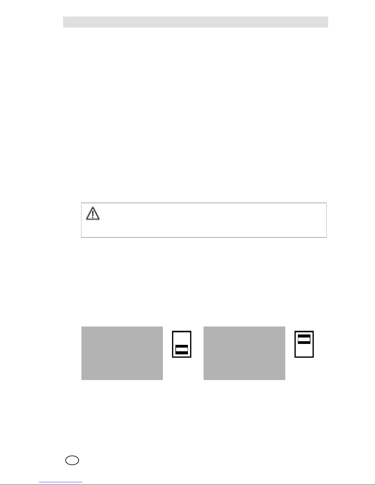
The Control Units 9010/20 LCD can be fed in alternating current from the electrical mains at a
voltage of 115 VAC ±15 % or 230 VAC ±15 % depending on the predisposition represented below, which is carried out using the appropriate selector.
Attention!
The electrical installation needs to be carried out by qualified personnel in compliance
with the prevailing standards, especially in areas where there is an explosion and fire
hazard.
TRANSFORMER TRANSFORMER
Fig. 8 Power Supply 230 VAC Fig. 9 Power Supply 115 VAC
230
115

Control Unit Models 9010 LCD and 9020 LCD
12
Installation
MSA
GB
Check the ELECTRICAL CONNECTIONS DIAGRAM in order to identify the line connection terminals L, N and EARTH. The Control Unit 9010/20 LCD is protected on the supply line by fuse F1
whose value is determined by the feed voltage, and in particular:
Fuse F1 - 250 mA for 230 VAC supply
Fuse F1 - 500 mA for 115 VAC supply
The electrical supply must not present variations in voltage greater than those indicated, sudden
flickers of voltage due to the connection of electrical loads of substantial magnitude, electrical disturbances caused by inductive and capacitive loads and incorrect contacts.
MSA shall not be held liable for malfunctions and/or damage caused by electrical disturbances
that are due to natural phenomena [e.g. lightning strikes].
We recommend protecting the equipment using appropriate external switches [automatic switches, differential switches] as close as possible to the equipment; the switches should be identified
by their function and should conform to the standards IEC 60947-1 and IEC 60947-3.
The 9010/20 LCD boards were tested and developed in compliance with the EMC directives and
the prevailing standards EMC [EN 50270]. In order to guarantee conformity with the EMC
standards, several rules need to be observed during the installation phase:
- Provide an earth connection or an equipotential connection without defects.
- Use an external energy source conforming to the EMC directives, use split EMC mains filters
for AC voltage feeds [115/230] and/or DC voltage feeds [24].
- Use diagrammed cables for DC supply [24 VDC] and for the sensors/transmitters, also the
control cables [reset, output 4/20 mA, RS485] need to be shielded.
- Use cables diagrammed with a minimum shielding of 80%, avoid junctions, use boxes of the
shielded type.
- Keep the signal cables separate from the supply cables, with a distance of at least 30 cm.
- External devices used [horns, flashers, motors, etc.] must by shielded from the radio frequen-
cies and conform to the EMC directives.
- Avoid installations in areas with a presence of strong electromagnetic fields.
DC power supply
Predisposition for 24 VDC power supply from external sources
The appropriately configured Control Units 9010/20 LCD can be supplied with either AC or DC
current. If both of the feeds are present, the DC current automatically takes over for AC when the
latter is lacking and vice-versa, without any discontinuity in operation.
Make the DC connections at terminals 4 [+] and 5 [-] of the back terminal board following the
polarity indicated on the CONNECTION DIAGRAM.
When the Control Units are connected with external battery backups, make sure that the voltage
remains within the values recorded in the TECHNICAL CHARACTERISTICS; the board is
equipped with appropriate indications for power outage at the mains or battery.
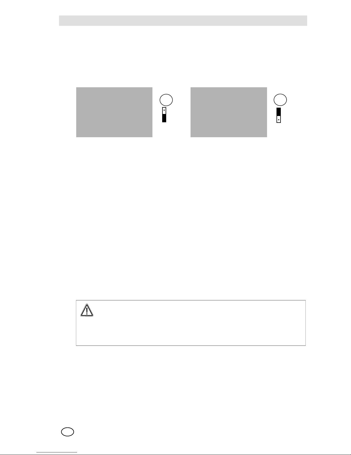
For 24 VDC power supplies from external sources [e.g.: battery backup, power supply modules,
etc.] the CV-18 Control Unit jumper needs to be predisposed in pos. 2-3 on terminals 4 and 5 as
represented below.
This input is protected by 2-amp fuse F3.
Attention!
Control Unit 9010/20 LCD is not predisposed for battery backup charging; this function
needs to be implemented by external devices.
MSA AUER
MSA
Installation
Control Unit Models 9010 LCD and 9020 LCD
13
GB
Predisposition for supplying auxiliary external circuits via the Control Unit
In the cases in which direct current is not available and makes it necessary to supply the auxiliary
circuits external to the Control Unit [e.g. relays, interfaces, transmitters, etc.], it is possible to provide 24 VDC at the heads of the terminals 4 [+] e 5 [-] predisposing jumper CV18 in position 1-2.
The maximum power that can be connected depended on the transformer mounted on the
Control Unit and on the sensors/transmitters used. This exit is protected by a 2-amp fuse F3.
For any technical problem, please contact the MSA Technical Support Department.
Sensor or transmitter connections
In the cases in which the Control Units are supplied in a pre-calibrated state for the required gas,
it is necessary for each sensor, identified by a serial number, to be connected to the Control Unit
or to the channel [A or B in the case of model 9020] which records the same number.
When the Control Units are connected to transmitters 4/20 mA, they can be freely connected with
respect to the particular configurations.
The connection of the sensor to the Control Unit must be carried out, unless there are different
instructions on the part of MSA, via shielded cable.
The number of conductors necessary for the connection of the sensor, planned during configuration, is indicated on the CALIBRATION DATA SHEET attached to the Instruction Manual while, in
order to know the minimum section that must be used, depending on the current consumed by the
sensor and on the length of the line, consult the diagrams attached to the manual.
The shielding of the connection cable to the sensor must be uniquely connected to the
screw or to the faston earth terminal adjacent to the back terminal board for connection of
the Control Unit, it is important that the shielding from the sensor side be carefully isolated
and absolutely not be connected to the earthing screw that is located inside the sensor
case. The case must be connected to earth via a different conductor to be fixed to the
screw predisposed on the outside of the box.
If it were necessary to employ more lengths of cable between the Control Unit and sensor, it is
necessary to make the joints via welds; it is a good rule of thumb to make welds also on the wire
terminals.
TRANSFORMER TRANSFORMER
Fig. 10 24 VDC Power Supply from internal source Fig. 11 24 VDC Power Supply from external source
F3
CV18
3
2
1
CV18
F3
3
2
1
Warning!
In the case of operation with catalytic combustion sensors: To guarantee the unambiguity of catalytic combustion sensor operation it must be made sure [e.g. by checking with
hand-held test instruments] each time before turning on the sensors and the system that
the environmental atmosphere to be monitored by the sensors is free of combustible
gases.

Control Unit Models 9010 LCD and 9020 LCD
14
Configuration
MSA
GB
5 Configuration
5.1 Control Unit Configurations
The board was designed and certified to satisfy Directive 94/9CE, better known as
ATEX Directive, in order to be suitable for monitoring gas and/or flammable vapours in the field
of the Lower Limit of Explosiveness [LIE] and in order to detect the deficiency or enrichment of
oxygen.
The directive imposes some functional links of the Control Unit with the aim of guaranteeing the
safety of the monitored area and therefore of the persons that operate it.
When jumper CV23 is done, the board operates in ATEX mode [default configuration].
In this case, the functioning of the Control Unit turns out to be very rigid and some modes of operation, available when the board is used for other aims, cannot be set.
IMPORTANT
With the functioning mode according to the ATEX Directive, particular importance is attributed to
the FAILURE function that, via the relative opto-isolator or relay, signals any out-of-service condition of the Control Unit, even if not attributable to a failure.
This prerogative, resulting from an exasperated operating condition as a function of safety, must
be kept in the debit account by the Designers of the installations monitored via the Control Unit if,
resulting from the FAILURE condition, is made to correspond to an important action in the operation of the installations themselves.
Among the situations that provoke the FAILURE condition, the following should be remembered:
- Entry in any of the Access Codes.
- Blocking of the alarms
5.2 Front Panel
Located on the front panel are:
- 4-digit back-lit LCD display [no. 2 in the case of model 9020]. On the display, beyond the value
of the concentration, different information is available, such as the engineering unit, delay
alarms, their possible blocking, the calibration and TIME OUT states, as well as the symbols
of reference to possible conditions of operational irregularity.
- 3 LED [C; W, A] for the optical indication of reaching the alarm levels.
- LED [F] for the optical indication of a possible failure or out-of-service condition.
- Pockets suitable for containing the identification of the type of gas that is monitored.
- 3 buttons, as represented below, to enable all of the operations necessary for managing the
Control Unit.
Enter key used in order to select the access codes and confirm the settings
of the data.
A green LED is inserted in the button that signals by continuous light that the
device is turned on and by flashing light the entry of an access code.
UP key for increasing the data to be modified in the access codes or for silencing and resetting the alarms
Down key for decreasing the data to be modified in the access codes or for
silencing and resetting the alarms
MSA AUER
MSA
Configuration
Control Unit Models 9010 LCD and 9020 LCD
15
GB
5.3 Configuration with relay outputs
The Control Units 9010 and 9020 are furnished with 4 indication relays, respectively, alarm, warning, failure and horn, while the caution output is normally opto-isolated [default configuration] at
which reference is made to the EXTERNAL CONNECTIONS DIAGRAM for the back terminal
board connections.
The use of the voltage-free contacts must be done in accordance with the electrical characteristics
of the contacts themselves recorded in the TECHNICAL CHARACTERISTICS. The relays used
are single exchange [SPDT] for the Alarm and Warning outputs, while only the contact [SPST] is
available for the Horn and Failure outputs.
The failure relay mounted on the board is a double exchange relay with the contacts in series in
order to satisfy the safety needs of the ATEX directive.
The board with the relay outputs provides the following predispositions:
- Relays installed and alarm configuration in access code 4
- Configuration via step 1 of access code 52: indication 1
- If utilised, the opto-isolated CAUTION in absence of the 24 VDC external power supply: CV22
in position 2-3 a CV18 in position 1-2.
5.4 Configuration with opto-isolated outputs
In substitution for the relays, all of the outputs related to the alarm set-points [C, W and A], to the
indication of possible failures or of the out-of-service states predicted if the Control Unit operates
according to the ATEX Directive as well as to the activation of the possible external acoustic alarm
device can be predisposed with opto-isolated outputs.
These outputs are independent for each channel, even with model 9020, with the exception of the
output related to the activation of the external acoustic device [HORN].
Opto-isolated outputs are available with a common transmitter [MSA 173 card] or common collector [MSA 174 card].
The electrical characteristics of the opto-isolators are recorded in the TECHNICAL CHARACTERISTICS section while, for the connections, see the EXTERNAL CONNECTIONS DIAGRAM,
which provide the power supply of the opto-isolators and therefore of the relays via an internal or
external 24 VDC power source.
The 9010/20 LCD with the opto-isolated outputs provides the following predispositions:
- Remove the relays from the respective sockets, mount the circuit with the opto-isolators having
a common transmitter or collector depending on the application
- Configuration via step 1 of access code 52: indication 2
- In order to use the opto-isolators with the 24 VDC power supply supplied by the board, connect
the jumpers:
Cv18 pos. 1-2, Cv22 of the base board without any solder points in pos. 1-2 or 2-3
Cv1 pos. 2-3 on opto-isolator board
- In order to use the opto-isolators with the 24V dc power supply supplied by an external source,
connect the jumpers:
Cv18 pos. 2-3, Cv22 of the base board without any solder points in pos. 1-2 or 2-3
Cv1 pos. 1-2 on opto-isolator board
For applicable examples, see drawing E07-3497 attached.
On model 9020 LCD, the relay outputs are in common with the two channels.

Control Unit Models 9010 LCD and 9020 LCD
16
Configuration
MSA
GB
5.5 Predisposed for input signal
The Control Unit 9010/20 LCD general purpose version, depending on the sensor or transmitter
to be connected, can be configured to receive signals in mV or in mA, check table for the hardware
predisposition of the Control Unit.
The software predisposition is made in Access Code 52, step 3:
- setting datum 1 selects an input signal in mV [ex. catalytic sensors].
- setting datum 2 accepts a 4/20 mA input signal for two-wire transmitters
[ex. electrochemical sensors]
- setting datum 3 accepts a 4/20 input signal for three-wire transmitters
[ex. infrared detectors, field transmitters].
The Control Units configured by setting data 2, 3 are automatically calibrated between
4 and 20 mA and do not need further checks.
Control Unit 9010/20 LCD version 4/20 mA article no. 10093585 / 10093584 is predisposed to accept in inputs only signals 4/20 mA from 2- or 3-wire transmitters, the calibration is automatically
made on the 4/20 mA input signal.
5.6 Output Signals
Analogue signals
The selection of the analogue type signal, relative to the condition of regular operation, is performed with Access Code 4, step 19.
0*20 mA, 4*20 mA, 20*0 mA and 20*4 mA signals are available.
The indication of the analogue type signal in the event of a failure is done with Access Code 4,
step 20.
The following signals are available: 0 mA, 2 mA, 4 mA, 20 mA or h [corresponding to the value of
the signal frozen at the moment of the failure].
It is possible to make corrections of the 4-20 mA analogue signal via steps 23 and 24 of access
code 4; in this way, the alignment with other purchased systems will be possible.
The behaviour of the analogue signal in correspondence to the various access codes is shown for
each of these.
RS485 signal
The serial output RS485, of the interactive type, can be utilised for the connection with Supervision
Systems, PLC, DCS, etc.
The data transmitted on a RS485 HALF DUPLEX type serial bus with MODBUS protocol, connected to a Supervision System are as follows:
configuration of the current Control Unit with the possibility of modification, concentration values
of the monitored substance, alarm and failure conditions, execution of the horn cut-out and reset
of the alarm state.
Upon request it is possible to furnish output RS485 in a redundant form.
The MSA Technical Support Department is at your service for any technical questions.
Remember that these configurations are normally made in the factory in accordance
with the specifications of the customer.

MSA AUER
MSA
Configuration
Control Unit Models 9010 LCD and 9020 LCD
17
GB
5.7 Failure function
Beyond the red alarm LED's, the Control Units are equipped with a yellow LED [FAILURE] which
signals possible individual malfunctioning states [individual for each channel with 9020].
The nature of the failures, a listing of which is recorded in Section 9, is shown via the display.
The indication in a remote zone is accomplished via the related relay [FAILURE], which is
equipped with two free voltage-free N/O contacts [SPST] connected in series to each other in order to guarantee the signalling.
In the ATEX version, the relay coil is normally energised.
With model 9020, the failure indication is common to the two channels when the indication
is predisposed with the relays or individual when predisposed with opto-isolated outputs.
A pre-existing alarm condition remains as such if the failure is subsequently detected,
while they are automatically blocked if the failure precedes the event that would have
caused it.
5.8 Alarms and overrange functions
Alarm Set points
The alarm set-points are designated as:
- Caution [C] caution level
- Warning [W] warning level
- Alarm [A] alarm level
- Overrange [EEEE] indication on the display of the full scale being exceeded
The exceeding of the alarm set-points will be displayed on the front panel via the red LED's and
causes the status of the opto-isolators and of the relays connected thereto to change.
The alarms can be configured via the various steps of Access Code 4, which, beyond setting the
intervention levels, enable the following choices:
- alarms for rising signals or falling ones.
- coils of the excited relays or unexcited ones in the non-alarm state.
- resetting of the manual alarm state, as per mode 1M or 2M, or automatic with mode 1A or 2A.
[see the attachment].
The horn cut-out and the manual reset of the alarms is carried out the same using the UP and
DOWN keys of the front panel or with the external pushbutton, possibly connected to the back terminal board, see EXTERNAL CONNECTIONS DIAGRAM.
When the offset and full-scale values change, the Control Unit 9010/20 configures the sets
of alarms as default ones; the default values of the sets of alarms should be considered in
a percentage of the range of measure.
In a manner limited to the ATEX version, the alarm set-points A and W are set from 1 to 80 %
of full scale, while the alarm set-point C is set from 1 to 100 % of full scale; the indication
of overrange is always connected and the alarms are configurable only on the rise.
The oxygen analysis can also occur in ATEX mode [%Vol], with a full scale 0-25%Vol and
with alarms without setting; the input signal in ATEX mode must originate from a 4/20 mA
transmitter, likewise ATEX certified [e.g. MSA/AUER DF 9500 transmitter].
In the non-ATEX version, with the unit of measure PPM it is possible to set average alarms
on 15 min [STEL] and/or on 8 hours [TWA].
The value of the STEL average will be available after 15 minutes from start-up or after 15 minutes
from the STEL setting in Access Code 4, step 14 [and/or step 18]. The sampling time for the calculation of the averages is 1 minute.

Control Unit Models 9010 LCD and 9020 LCD
18
Configuration
MSA
GB
STEL average CALCULATION = sum of last 15 readings /15 [any negative values are considered 0 ppm].
The value of the TWA average will be available after 480 minutes [8 hours] from start-up or after
480 minutes from the setting. TWA in Access Code 4, step 14 [and/or step 18]. The sampling time
for the calculation of the averages is 1 minute.
TWA average CALCULATION = sum of last 480 readings /480 [any negative values are considered 0 ppm].
Overrange
The purpose of the OVER RANGE function is to indicate when 100 % of the full scale is exceeded,
and, if activated, this exceeding causes the symbol EEEE to be displayed and the external acoustic device to be activated, which can then be silenced by pressing one of the UP or DOWN keys.
In the ATEX version, the OVER RANGE indication is always activated.
The reset of all the alarm set-points is commutated automatically into 1M mode, independently of
the previously made choice, except that it is already in 2M mode.
The EEEE indication will persist until the signal remains greater than the full scale value.
When the signal falls back below the full scale, the EEEE symbol alternates with the current indication of the concentration [4 sec.: EEEE; 1 sec.: display of the concentration] and the acoustic
device is activated anew.
When the concentration falls back below the alarm levels and in concurrence with the manual reset of one or more set-points, the cancellation of EEEE occurs and the reset modes return as per
configuration.
If necessary, the CAUTION set-point, whose intervention value will be set to 100 % of full scale,
can be used for the remote indication of OVER RANGE.
5.9 Starting the Control Unit
Before energising the Control Unit, make sure that:
- the mechanical and electrical installation conforms to what is described in section 4 and nev-
ertheless conforms to the prevailing standards.
- that the setting of the jumpers related to the voltage change and those of the hardware config-
uration conform to the CALIBRATION DATA SHEET included with the Instruction Manual.
- that the serial number of the Control Unit corresponds to that of the sensor or of the connected
sensor.
After having applied voltage, the Control Unit for about 1 minute performs the self-diagnostics for
each channel in order to check the correct operation of the various circuits and of the signalling
devices.
During this phase, the alarms are blocked, and the 4/20 mA analogue output is placed as
per the configuration of Access Code 4, step 20; the failure indication for the ATEX version
is active.
At the end of the self-diagnostics, the Control Unit is placed in regular operating mode.

MSA AUER
MSA
Configuration
Control Unit Models 9010 LCD and 9020 LCD
19
GB
5.10 Jumpers predisposition
BASE BOARD - HARDWARE CONFIGURATIONS [normally performed in the factory]
The horn relay is normally unexcited with a normally open contact; if a normally closed contact is
desired, the track of CV 19, pos 2-3 needs to be cut and a drop of solder needs to be inserted in
pos.1-2.
Function
Component side /
solder side
NOTES
CV 13
AandB
pos. 1-2 RS485 redundant Drop of solder
[component side]
CV 13
AandB
pos. 2-3 Drop of solder
[component side]
Configurations
reserved for MSA default: closed
CV 14 pos. 1-2 Configurations re-
served for MSA - default: open
Cv 15 pos. 1-2 Open - gen. purp. board
Closed - 4/20 mA board
Drop of solder
[component side]
Depending on the
board
CV 16 pos. 1-2 Open - 38400 baud
Closed - 9600 baud
Drop of solder
[component side]
Default: open [x RS485]
CV 17 pos. 1-2 Drop of solder
[component side]
Configurations
reserved for MSA default: open
CV 18 pos. 1-2 24 VDC power supply
generated within board
Jumper, component
side
e.g. for services
CV 18 pos 2-3 24 VDC power supply
from outside board
Jumper, component
side
e.g. for battery
backup
Default
CV 19 pos. 1-2 Horn contact n.c. Drop of solder
[solder side]
Default: open
CV 19 pos. 2-3 Horn contact n.o. Drop of solder
[solder side]
Default: closed
CV 20 pos. 1-2 Drop of solder
[component side]
Configurations
reserved for MSA default: open
CV 22 pos. 1-2 Opto-isolated caution
output
Drop of solder
[component side]
Needs an external
negative on
terminal 7
CV 22 pos. 2-3 Opto-isolated caution
output
Drop of solder
[component side]
The negative is
common to the default board
CV 23 pos. 1-2 Closed - ATEX version
Open - non-ATEX
version
Drop of solder
[component side]
Default: closed
CV 24 pos. 1-2 Closed - UC 9010
Open - UC 9020
Drop of solder
[component side]
CV 25 pos. 1-2 Watch-dog activation Jumper, component
side
Default: closed

Control Unit Models 9010 LCD and 9020 LCD
20
Configuration
MSA
GB
MSA OPTO-ISOLATOR BOARDS 173 and 174 [board installed by request]
CONFIGURATION 9010/20 LCD FOR SENSORS/TRANSMITTERS FOR GENERAL
PURPOSE BOARD
CV 1 pos. 1-2 External power supplies Drop of solder
[component side]
For applications with
separate external
power supplies
CV 1 pos. 2-3 Internal power supplies Drop of solder
[component side]
Default configuration
Connection type
CURRENT LOOP
TWO-WIRE
CURRENT
LOOP
THREE-WIRE
SENSOR
THREE-WIRE
SENSOR
THREE-WIRE
Type of transmitter Series 27 Df 9500
UltimaXE [2-wire]
Ultima
XE/XIR/XI
RG-3LCD
Catalytic
Thermocondu.
Sensor/trasm.
power supply
VOLTAGE VOLTAGE CURRENT VOLTAGE
Input signal mA mA mV mV
Points to short circuit
CH A CH B
CV1 CV1 pos. 2-3 pos. 2-3 pos. 1-2 pos. 2-3
CV2 CV2
CV3 CV3
CV4 CV4
CV5 CV5
CV6 CV6
CV7 CV7
CV8 CV8
CV9 CV9 pos. 1-2 pos. 1-2 pos. 1-2 pos. 1-2
CV10 CV10
CV11 CV11
CV12 CV12

MSA AUER
MSA
Configuration
Control Unit Models 9010 LCD and 9020 LCD
21
GB
CONFIGURATION 9010/20 LCD FOR SENSORS/TRANSMITTERS FOR GENERAL
PURPOSE BOARD [continued]
Connection type
FOUR-WIRE
SENSOR
FOUR-WIRE
SENSOR
SENSOR
THREE-WIRE
Type of
transmitter
Catalytic
Thermoconduct.
Oxygen cell
Thermoc. Cell
For analysers
Semiconductor D-8201
Sensor/trasm.
power supply
CURRENT VOLTAGE CURRENT
Input signal mV mV mV
Points to short
circuit
CH A CH B
CV1 CV1 pos. 1-2 pos. 2-3 pos. 1-2
CV2 CV2
CV3 CV3
CV4 CV4
CV5 CV5
CV6 CV6
CV7 CV7 *
CV8 CV8
CV9 CV9 pos. 1-2 pos. 1-2 pos. 2-3
CV10 CV10
CV11 CV11 *
CV12 CV12
NOTES
bridge closed
* depending on the
range and the gas
Control Unit Models 9010 LCD and 9020 LCD
22
Configuration
MSA
GB
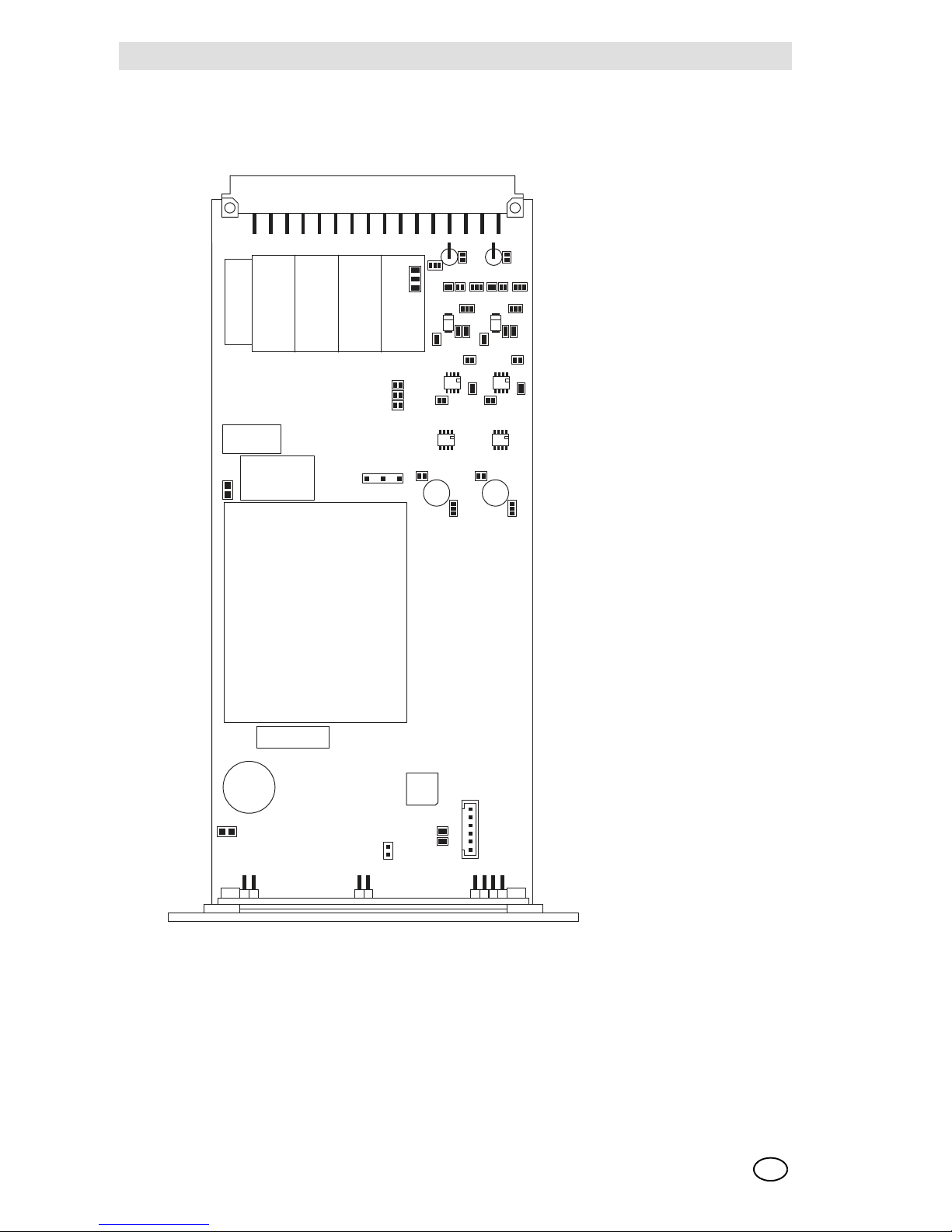
For the location of the jumpers, consult the accompanying topographical diagram.
Board 9010/20 LCD with article no. 10093585 / 10093584 for individual 2-wire or 3-wire 4/20 mA
inputs, has the following hardware predispositions, which are recommended not to be modified:
Cv3, Cv4, Cv 6, Cv8, Cv9 pos 1-2, Cv10.
Fig. 12 Jumpers
CV22
**CV19
123
CV3A
CV3B
CV5A
CV2A
CV13A
CV5B
CV2B
CV13B
123
123
123
123
123
CV9A
CV9B
CV4A
CV12A
CV11A
CV4B
CV12B
CV11B
CV6A
CV6B
CV8A
CV7A
CV8B
CV7B
CV15
CV16
CV17
CV10A
CV10B
1
2
3
CV1A
1
2
3
CV1B
1
2
3
CV13
CV14
CV20
CV25
CV24 CV23
**CV19 PLACE ON SOLDER LAYER

MSA AUER
MSA
Setting Parameters
Control Unit Models 9010 LCD and 9020 LCD
23
GB
6 Setting Parameters
As a rule, the Control Units are delivered already configured and calibrated by MSA based on the
specifications provided by the customer.
The CALIBRATION DATA SHEET, in which the main configuration data are recorded, accompanies the Instruction Manual delivered with the Control Unit.
Modifications can be made via the various steps in each of the Access Codes recorded below.
To identify the various steps contained in each Access Code, consult the INDEX in Section 6.
6.1 Use of the buttons for access to the codes
Access to the Access Codes 1, 3, 5, 123 and 223 is accomplished by holding down the
ENTER button with the board energised for approximately 3 seconds until the green LED incorporated in the button itself flashes.
For all of the other Codes, for the purpose of ensuring greater protection against unwanted access, the button needs to already be pressed before the Control Unit is turned on or via
Access Code 123 if the Control Unit is already turned on.
Mod. 9010 - Example for use of the buttons for access to the Access Codes
The Control Unit automatically returns step by step to regular operation if the buttons are
not pushed within two minutes. [TIME-OUT function]
The TIME-OUT function may possibly be disabled [see item Section 6.3]
Access Code 1 Calibration operations
Access Code 2 Settings for particular operating conditions
Access Code 3 Simulation and functionality operations
Access Code 4 Configuration operations
Access Code 7 Setting the address of the peripherals
Access Code 52 Initialisation operations
Access Code 53 Default settings
Access Code 123 Acceptance of the following Access Codes protected without
de-energisation: 2, 4, 7, 52, 53
Access Code 223 Operations for the setting, the use and the modification of the password
a. Hold down the ENTER button until the incorporated green LED flashes.
b. Next, press the UP button one or more times until the desired number related to the
Access Code is selected.
c. Confirm the selection by pressing the ENTER only once.
d. P1 appears.
e. Press the ENTER only once if you want to enter into the P1 step or press the UP button one
or more times until the desired step is selected.
f. Press the ENTER button only once to confirm the selection.
g. Press the UP or DOWN buttons to modify the indication in the display if necessary.
h. Once the modification has occurred, confirm the new indication by pressing the
ENTER button only once.
i. In order to exit any Access Code, press the ENTER button two times in a row within
two seconds. Depending on the position within an Access Code, it may be necessary to repeat the manoeuvre another two or three times.

Control Unit Models 9010 LCD and 9020 LCD
24
Setting Parameters
MSA
GB
Mod. 9020 - Example for use of the buttons for use of the Access Codes
or:
ATEX version – Operating modes of the Control Unit with one of the Access Codes entered
When the ENTER button is released:
- the ALARM INHIBIT tag flashes in the displays for both of the channels.
- All of the alarm set-points are blocked and frozen in the state in which they are found when the
button is released.
- The horn, if already activated, is silenced with the exception of the EEEE condition.
- The FAILURE relay is in a state of failure.
- The value of the analogue signals of both the channels is a function of the preselection made
with the step.
- P 20 of Access Code 4 with the exception of step P11 of Access Code 3. [Simulation test of
unblocked alarms]
Standard version – Operating modes of the Control Unit with one of the Access Codes entered
When the ENTER button is released:
- in the display of both the channels, the ALARM INHIBIT tag flashes
- All of the alarm set-points are blocked and frozen in the state in which they are found when the
button is released.
- The horn, if activated, is deactivated by the Control Unit with the exception of the EEEE con-
dition.
a. Hold down the ENTER button until the incorporated green LED flashes.
b. Next, press the UP button one or more times until the desired number related to the
Access Code is selected.
c. Confirm the selection by pressing the ENTER only once.
d. CHa appears in the upper display.
e. Press ENTER to operate with channel A.
f. P1 appears in the upper display.
g. Proceed as described in item e] in the example related to model 9010.
h. Press the UP button to operate with channel B
i. CHb appears; Press the ENTER button to confirm the choice.
j. P1 appears in the lower display.
k. Proceed as described in item e) in the example related to model 9010.

MSA AUER
MSA
Setting Parameters
Control Unit Models 9010 LCD and 9020 LCD
25
GB
The state of analogue output signals are as follows, depending on the preselected Access Code:
Access Code 1:
channel being calibrated as set in step P2 of Access Code 2
of the other channel: fluctuating
Access Code 2, 7, 123 and 223:
fluctuating for both the channels if the selection was made via Access Code 123, while they are
equal to 0 mA if the selection occurred via the ENTER button when the Control Unit is turned on.
Access codes 3 and 5:
fluctuating for both channels.
Access codes 4, 52 and 53:
- selected channel: 0 mA
- the other channel: fluctuating if the selection was made via Access Code 123, while it is equal
to 0 mA if the selection occurred via the ENTER button when the Control Unit is turned on.

Control Unit Models 9010 LCD and 9020 LCD
26
Setting Parameters
MSA
GB
6.2 Access Code 1 - Calibration operations
Press the Enter button until the respective green LED flashes, set 1 with the Up button, confirm with Enter, select channel A or B [only for model 9020 LCD] with the Up and Down buttons,
therefore confirm with Enter.
To exit from the access code, press the Enter button twice quickly.
Step Function NOTES
P1 Zeroing - [to be carried out in clean air] – confirm with Enter,
no adjustment is necessary
Blocked alarms 4/20 mA analogue
output as per configuration in Access
Code 2, step 2.
Caution with a
board in the ATEX
version, the 4/20 mA
analogue output is
set at 2 mA
P2 Setting of the concentration of the calibration gas contained in
the cylinder with the Up and Down [the default value is 50 for a
scale from 0 – 100 %] - confirm with Enter
P3 Span calibration, make the gas in the sensor flow - confirmation
of making the calibration at the concentration value provided in
P2 - confirm with Enter
P4 Viewing the concentration detected by the sensor after the cal-
ibration - confirm with Enter
P5 Viewing the magnitude of the input signal related to the per-
formance of the Control Unit. Confirm with Enter [valuation
range: 0 mV = minimal signal; 200 mV = maximum signal]
P6 Setting of the time interval between two calibrations
[Values that can be set: 0999 days] - Confirm with Enter
If the time interval set for the P6 step has expired, the CAL tag
flashes in the display.
P7 Calibration enabled / disabled only for 4/20 mA configured
boards A=enabled, nA=disabled – select with Up and Down,
confirm with Enter
P8 Indication enabled / disabled with the CAL tag for reduction of
the sensor signal under 50% with respect to the preceding calibration.
A=enabled , nA=disabled - the CAL tag will be fixed
P20 Memorisation of board configuration as per customer calibra-
tion data sheet
Selective for channel

MSA AUER
MSA
Setting Parameters
Control Unit Models 9010 LCD and 9020 LCD
27
GB
6.3 Access code 2 - Settings for particular operating conditions
The Access Code is accepted if the ENTER button is kept pressed when the Control Unit is turned
on, or first typing the Access Code 123.
To exit from the access code, press the Enter button twice quickly
Step Function NOTES
P1 Disabling/enabling of the TIME OUT function
A= enabled [Tag TIME-OUT spent]
d= disabled [TIME-OUT tag flashing]
Common to both channels
P2 Setting the type of analogue output of the selected chan-
nel for the calibration and programming
h = frozen, F = fluctuating, 0 = zero mA, 4 = four mA,
20 = valves mA
The boards in the ATEX
version are not configurable; the output is equal to
the configuration in Access
Code 4, P20.
P3 Blocking the alarms related to the selected channel
A = unblocked alarms, nA = blocked alarms
The flashing ALARM INHIBIT tag is shown in the display
of the channel with blocked alarms.
The 4-20 mA analogue signal is active.
In the ATEX version, the
FAILURE relay remains in
a failure state, even after
exiting the Access Code,
while the Horn output for
the acoustic device is activated only when the OVER
RANGE set-point is exceeded concurrently with
showing the EEEE in the
display.
P4 Enabling / disabling indication of low external 24 VDC
power supply with failure relay intervention and display in
the LOU 1 display - the display alternates between concentration and LOU 1.
Available only with primary
115/230 VAC
power supply
P5 Enabling / disabling indication of low external 115/
230 VAC power supply with failure relay intervention and
display in the LOU 2 display - the display alternates between concentration and LOU 2.
Available only with external
24 VDC power supply

Control Unit Models 9010 LCD and 9020 LCD
28
Setting Parameters
MSA
GB
6.4 Access code 3 - Simulation and functionality operations
Press the Enter button until the respective green LED flashes, set 3 with the Up button, confirm
with Enter, select channel A or B [only for model 9020 LCD] with the Up and Down buttons, therefore confirm with Enter.
Step Function NOTES
P1 Test of functionality of the LCD display. Check the efficiency of
all the segments of the display
P2 Simulation of the increase in concentration via the UP and
DOWN buttons with alarms blocked. In correspondence to the
various alarm set-points, the corresponding LED's light up, but
the relays are not activated.
Press the ENTER
button twice in succession in order to
exit
P3 Viewing the value of the current set for supplying power to the
sensor. If the configuration provides for constant voltage power
supply, VOL is shown.
P4 Viewing the effective value of the supply current of the sensor.
The value of the current is displayed even in the case that the
sensor is powered with constant voltage.
P5 Display in automatic sequence of the following information:
- set offset value
- set full-scale value
- set sensor feed current value
[if stabilised in voltage, the indication VOL appears]
- current value consumed by the sensor
- current value at the output of the power supply
the following displays, in automatic sequence, referred to the
alarm set-points with the LED lit:
- direction of alarm activation [in the ATEX version only pro-
vided for rising value]
- alarm set-point value
- reset mode [1A; 1M; 2A; 2M]
- relay state: energised [E] / non-energised [dE]
[in the ATEX version, the Failure relay is energised during
regular operation]
- value of the alarm activation delay [in seconds]
range of the analogue output signal during regular operation:
020; 420; 200; 204mA
range of the analogue output signal in the case of a failure: 0,
2, 4, 20 mA or h [frozen]
To continuously display one of the data,
the ENTER button
must be held down.
P6 Viewing the average Stel or TWA value associated with the
Warning alarm
Available only with
the unit of measure
PPM
P7 Viewing the average TWA or Stel value associated with the
Alarm alarm
Available only with
the unit of measure
PPM
P8
P9
P10

MSA AUER
MSA
Setting Parameters
Control Unit Models 9010 LCD and 9020 LCD
29
GB
6.5 Access code 4 - Configuration operations
The Access Code is accepted if the ENTER button is kept pressed when the Control Unit is turned
on, or first typing the Access Code 123.
P11 Simulation of the increase in concentration via the UP and
DOWN buttons with alarms unblocked.
In addition to the LED's, the alarm relays [unless they are
blocked in Access Code 2, step 3] are activated in correspondence to the various alarm set-points.
To silence the
acoustic alarm,
press the
ENTER button.
Press two times in
succession in order
to exit.
P12 Efficiency test of the digital outputs
A change of state of all the opto-isolators and therefore of the
relays connected thereto is detected [even if the alarms were
blocked in Access Code 2, step 3]
Indication 1 = state of the opto-isolators as in the configuration
performed via Access Code 4
Indication 2 = obtained by pressing the Up button: All of the
opto-isolators change in state compared to condition 1.
n.b.: Upon exit from step 12, the state of the opto-isolators will
be automatically re-comutated back into condition 1
[In the ATEX version, the FAILURE
state does not
change]
if it has already commutated automatically when any
Access Code is entered.
Step Function NOTES
Step Function NOTES
P1 Setting of the supply current of the catalytic sensor.
Individual for each channel. Admissible values 5500 mA
The step is automatically skipped if the power supply is provid-
ed as constant voltage
Only for passive
sensors
P2 Setting of the FAILURE current for power supply interruptions.
Individual for each channel. Permissible values 1500 mA
Reaching the preset
value activates the
Failure relay
P3 Setting the value related to the negative drift of the analogue
signal. Permissible value 0 -10 % of the full scale
Reaching the preset
value activates the
FAILURE relay and
d1 is displayed
P4 Selection of the Unit of Measure: LEL, LELm, PPM, %VOL,
g/m
3
, no unit of measure
[In the ATEX version, the Units of Measure LEL , LELm and
%VOL [oxygen] are the only ones that can be selected; the
selection % Vol for oxygen analysis is possible only after the
configuration of Access Code 52, step 3 with setting 2 or 3,
depending on the type of transmitter]
P5 Setting the offset value
[Permissible values 09000] - Individual for each channel
In the ATEX version,
the offset value is
zero
P6 Setting the full scale value.
[Permissible values: 09000] - Individual for each channel.
The variation of the full scale value modifies the set-point val-
ues of the alarms and the calibration setting datum at Step 2 of
Access Code 1.
The precision of the control module of 1% is guaranteed to be
compatible with the range of measurement, offset value [P5]
and full scale value [P6] selected.
In the ATEX version,
the permissible values are between 1
and 100 for the combustible gas and
0-25 % for oxygen]

Control Unit Models 9010 LCD and 9020 LCD
30
Setting Parameters
MSA
GB
SETTINGS OF THE ALARM SET-POINT “C” [CAUTION] - OUTPUT WITH OPTO-ISOLATOR
P7 Settings of the alarm set-point
Selection of the direction of activation of the alarms
U: rising, d: falling
Setting the intervention threshold
Permissible values: 0100 % of the full scale
Also valid in the
ATEX version to allow remote indication of the EEEE
indication if set at
100 % of the full
scale
P8 Selection of the opto-isolator state in regular operation
E: conducting / Energised dE: not conducting / not Energised
P9 Selection of the reset mode.
Sequences: 1A; 1M; 2A; 2M
[see attachment 1]
P10 Setting the delay time for the indication of the alarm
Permissible values: 09999 sec
SETTINGS OF THE ALARM SET-POINT “W” [WARNING] - OUTPUT WITH RELAY
P11 Settings of the alarm set-point
Selection of the direction of activation of the alarms
U: rising, d: falling
Setting the intervention threshold
In the ATEX version,
the permissible values are
080 % of the full
scale.
P12 Selection of the opto-isolator/relay state in regular operation
E: conducting / Energised, dE: not conducting / not Energised
P13 Selection of the reset mode.
Sequences: 1A; 1M; 2A; 2M
[see attachment 1]
P14 Setting the delay time for the indication of the alarm
Permissible values: 09999 sec
With the Unit of Measure PPM, the Control Unit shows the
selection SteL, TuA [TWA] and norM; by selecting norM it is
possible to set the delay.
SETTINGS OF THE ALARM SET-POINT “A” [ALARM] - OUTPUT WITH RELAY
P15 Settings of the alarm set-point
Selection of the direction of activation of the alarms
U: rising, d: falling
Setting the intervention threshold
In the ATEX version,
the permissible values are
080 % of the full
scale.
P16 Selection of the opto-isolator/relay state in regular operation
E: conducting / Energised, dE: not conducting / not Energised
P17 Selection of the reset mode.
Sequences: 1A; 1M; 2A; 2M
[see attachment 1]
P18 Setting the delay time for the indication of the alarm
Permissible values: 09999 sec
With the Unit of Measure PPM, the Control Unit shows the
selection SteL, TuA [TWA] and norM; by selecting norM it is
possible to set the delay.
P19 Selection of the analogue output signal range
020; 420; 200; 204mA
P20 Selection of the analogue output signal value in the case of fail-
ure
0; 2; 4; 20 mA or h [frozen]
Step Function NOTES
 Loading...