

Page 1
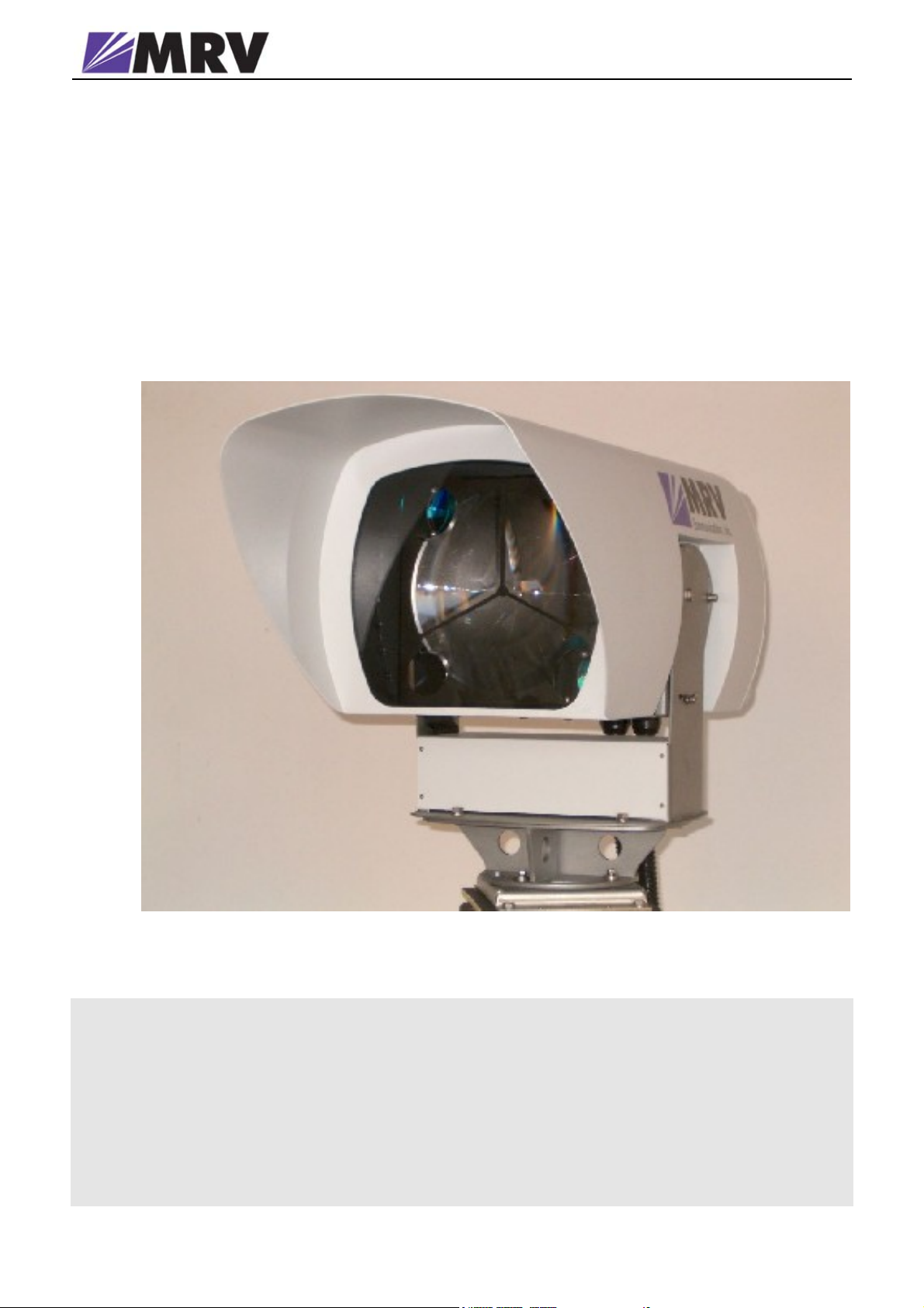
Wireless Optical Communications
TS5000/XXX
(TS5000G/XYZ/V**, TS5000/XYZ/V**,
TS5000/ETH/V*, TS5000/4U1/V*)
Installation Manual
Page 2

WIRELESS OPTICAL COMMUNICATIONS
Installation Manual
Document Number 4705000, Rev. 2.7
February 2008
© MRV Communications, Inc.
Web site: www. mrv.com
Page 3

Table of Contents
STANDARDS
Standards Compliance ............................................................................i
FCC Notice ...............................................................................................i
CE Mark ...................................................................................................i
Other Standards .....................................................................................ii
MRVTM Laser Safety Certification........................................................ii
About this Installation Manual ............................................................iii
SAFETY REQUIREMENTS
Before Installing ....................................................................................iv
Before Powering On ..............................................................................iv
When Installing ......................................................................................iv
Servicing .................................................................................................. v
Introduction............................................................................................vi
MRV Communications, Inc. – Installation Manual
CHAPTER 1 - THE PRODUCT
Models.......................................................................................................1
General Description ................................................................................3
Front................................................................................................3
Back.................................................................................................4
A. TS5000/G Standard Model (w/o Fusion and with one power
supply................................................................................................... 5
B. TS5000/G-F (Standard Model including Fusion Option) ..............9
C. TS5000/155 (w/o Fusion and with one power supply)...................10
D. TS5000/155-F (Standard Model including Fusion option) ..........14
E. TS5000/ETH (Ethernet System)..................................................... 17
F. TS5000/4U1 (4E1 or 4T1 System)................................................... 19
Loop and Remote Loope Operation Mode..........................................21
Heating ...................................................................................................21
Monitoring & Management Options...................................................22
Management.................................................................................22
Dry contact ...................................................................................22
RSM............................................................................................... 22
Typical Connection................................................................................23
Page 4

MRV Communications, Inc. – Installation Manual
CHAPTER 2 - SITE SURVEY
Line of Sight...........................................................................................24
Orientation............................................................................................. 24
Location & Range.................................................................................. 24
Mounting Environment & Stability.....................................................27
Transmitting through a Window.........................................................29
CHAPTER 3 - INFRASTRUCTURE
Power......................................................................................................30
Data/Signal Cabling ..............................................................................30
CHAPTER 4 - BENCH TEST
TS5000/G & TS5000/G-F......................................................................32
TS5000/155 & TS5000/155-F................................................................33
TS5000/ETH...........................................................................................34
TS5000/4U1............................................................................................34
Test configurations................................................................................35
Display and Results............................................................................... 37
SNMP Management Setting and Operation....................................... 39
CHAPTER 5 - INSTALLATION
Accessories .............................................................................................40
Mounting................................................................................................43
Accessories....................................................................................43
Attachment of the Transceiver...................................................43
Particular Figure Cases/Techniques.................................................... 45
CHAPTER 6 - AIMING PROCEDURE
Powering on the TereScope.................................................................. 46
Transceiver Alignment..........................................................................47
Coarse Alignment.........................................................................47
Fine Alignment.............................................................................47
Link Operating Test..............................................................................50
Installation Log......................................................................................50
Installation Completion ........................................................................51
CHAPTER 8 - MAINTENANCE
Periodic Visits........................................................................................ 53
Page 5

MRV Communications, Inc. – Installation Manual
APPENDIX A. Product specifications
AP PENDI X B. Digital Readout vs. Distance
APPENDIX C. Unpacking Instructions
AP PENDI X D. Tool Kit, Equipment and Materials
AP PE NDI X E . TereScope Bench Test Procedure
AP PENDI X F. Effect of wind on TereScope Devices
APPENDIX G. FSO Chaining
AP PE NDI X H . Installation Log
AP PE NDI X I . Power Supply Replacement
A P P E N D I X J . TS5000/155 AND TS4000/155 ENHANCEMENTS
Page 6

MRV Communications, Inc. – Installation Manual
Standards
Standards Compliance
UL 1950; CSA 22.2 No 950; FCC Part 15 Class A; CE-89/336/EEC, 73/23/EEC
FCC Notice
WARNING: This equipment has been tested and found to comply with the limits for a Class A digital
device, pursuant to Part 15 of the FCC Rules. These limits are designed to provide reasonable protection
against harmful interference when the equipment is operated in a commercial environment. This
equipment generates, uses, and can radiate radio frequency energy and, if not installed and used in
accordance with the instruction manual, may cause harmful interference to radio communications.
Operation of this equipment in a residential area is likely to cause harmful interference in which case the
user will be required to correct the interference at his own expense.
The user is cautioned that changes and modifications made to the equipment without approval of the
manufacturer could void the user’s authority to operate this equipment
It is suggested that the user use only shielded and grounded cables when appropriate to ensure
compliance with FCC Rules.
CE Mark
The CE mark symbolizes compliance with the EMC directive of the European Community. Such
marking is indicative that the specified equipment meets or exceeds the following technical standards:
• EN 55022 - Limits and Methods of Measurement of Radio Interference Characteristics of
Information Technology Equipment
• EN 50081-1- Electromagnetic compatibility - of Radio Interference Characteristics of
Information Technology Equipment Generic Emission standard Part 1 – Residential
commercial and light industry environment
• EN 50082-1 - Electromagnetic compatibility -- Generic immunity standard Part 1:
Residential, commercial and light industry environment
• EN61000-4-2 (previously IEC 1000-4-2) - Electromagnetic compatibility for industrial-
process measurement and control equipment Part 4: Section 2 - Electrostatic discharge
requirements
• EN61000-4-3 (previously IEC 1000-4-3) - Electromagnetic compatibility for industrial-
process measurement and control equipment Part 4: Section 3 - Radiated electromagnetic
field requirements
• EN61000-4-4 (previously IEC 1000-4-4) - Electromagnetic compatibility for industrial-
process measurement and control equipment Part 4: Section 4 - Electrical fast
transient/burst requirements
• EN61000-4-5 - Electromagnetic compatibility for industrial-process measurement and
control equipment
Part 4: Section 5 – Surge Immunity requirements
• EN61000-4-6 - Electromagnetic compatibility for industrial-process measurement and
control equipment
Part 4: Section 6 – Immunity to conducted disturbances induces by radio frequency fields
• EN61000-4-8- Electromagnetic compatibility for industrial-process measurement and
control equipment
Part 4: Section 8– Power frequency magnetic field immunity requirements
• EN61000-4-11 – Electromagnetic compatibility for industrial-process measurement and
control equipment Part 4: Section 11 – Voltage dips short interruptions and voltage
variations immunity requirements
• EN61000-3-2 – Harmonic standard
• EN61000-3-3 – Voltage Fluctuation and Flicker standard
• CISPR 22 - Radiated and Line-conducted Class A
• EN 60950 - ITE Safety
i
Page 7

MRV Communications, Inc. – Installation Manual
Other Standards
1. CISPR 22: 1993
AS/NZS 3548: 1995, Class A,
Joint Amendment No. 1: 1997, Joint Amendment No. 2: 1997
2. EN 60950+A1+A2+A3+A4+A11
ACA TS001-1997
AS/NZS 3260: 1993 A4: 1997
ITU G.703, G.704, G.706,G.736, G.737, G.738, G739, G740, G.775, G.823.
MRV ™ Laser Safety Certification
The TereScope is designed, built, and tested to be eyesafe, even if the output beams are viewed directly,
provided that no magnifying optics are used.
This product is Class 1M according to the American National Standard for Safe Use of Lasers ANSI
Z136.1-1993 provided that there is not a reasonable probability of accidental viewing with optics in the
direct path of the beam where the TereScope is installed.
This product is Class 1M according to the International Standard of the International Electro technical
Commission IEC 60825-1, Amendment 2, January 2001 entitled “Safety of laser products.” The
following explanatory label is applicable to these products:
LASER RADIATION
DO NOT VIEW DIRECTLY WITH OPTICAL INSTRUMENTS
(BINOCULARS OR TELESCOPES)
CLASS 1M LASER PRODUCT
This product complies with United States FDA performance standards for laser products except for
deviations pursuant to Laser Notice No. 50 as published in June 2001, which allows for the use of the
IEC 60825-1 classification standard. Under this standard, these products are Class 1M.
A ‘Declaration of Conformity’, in accordance with the above standards, has been made and is on file at
MRV.
Disclaimer
MRV reserves the right to modify the equipment at any time and in any way it sees fit in order to improve it.
MRV provides this document without any warranty of any kind either expressed or implied, including, but not
limited to, the implied warranties of merchantability or fitness for a particular purpose.
Although much care has been taken in the preparation of this document, omissions and errors may still exist.
Therefore, the customer is advised to exercise due discretion in the use of the contents of this document since
the customer bears sole responsibility.
Trademarks
All trademarks are the property of their respective holders.
Copyright © 2007 by MRV
All rights reserved. No part of this document may be reproduced without the prior permission of MRV.
This document and the information contained herein are proprietary to MRV and are furnished to the
recipient solely for use in operating, maintaining and repairing MRV
may not be utilized for any purpose except as stated herein, and may not be disclosed to third parties
without written permission from MRV. MRV
specifications in order to improve reliability, function or design.
reserves the right to make changes to any technical
equipment. The information within
ii
Page 8

MRV Communications, Inc. – Installation Manual
About this Installation Manual
Audience
This manual is intended for the user who wishes to install, operate, manage and
troubleshoot TereScope5000.
Qualifications
Users of this guide are expected to have working knowledge of:
• Electro-optical equipment
• LAN equipment (Layer 2 and 3)
• License to install equipment on buildings/elevated structures
• License to work with power line (mains) voltages 110/230 Vac
Training
Installers are required to do a training course on MRV TereScopes that includes:
• IR links (site survey, installation equipment, alignment, etc.)
• Indoors and outdoors installation
• On-the-job-training
• Proficiency tests
Experience
Installers are required to have experience in coax cable TV home pass installation,
PTT home pass installation, LAN installation, IR equipment installation, and home
electrical wiring.
Authorization
When all the requirements specified above (namely, Qualifications, Training, and
Experience) have been met, the installer must receive authorization from MRV
certifying eligibility.
iii
Page 9
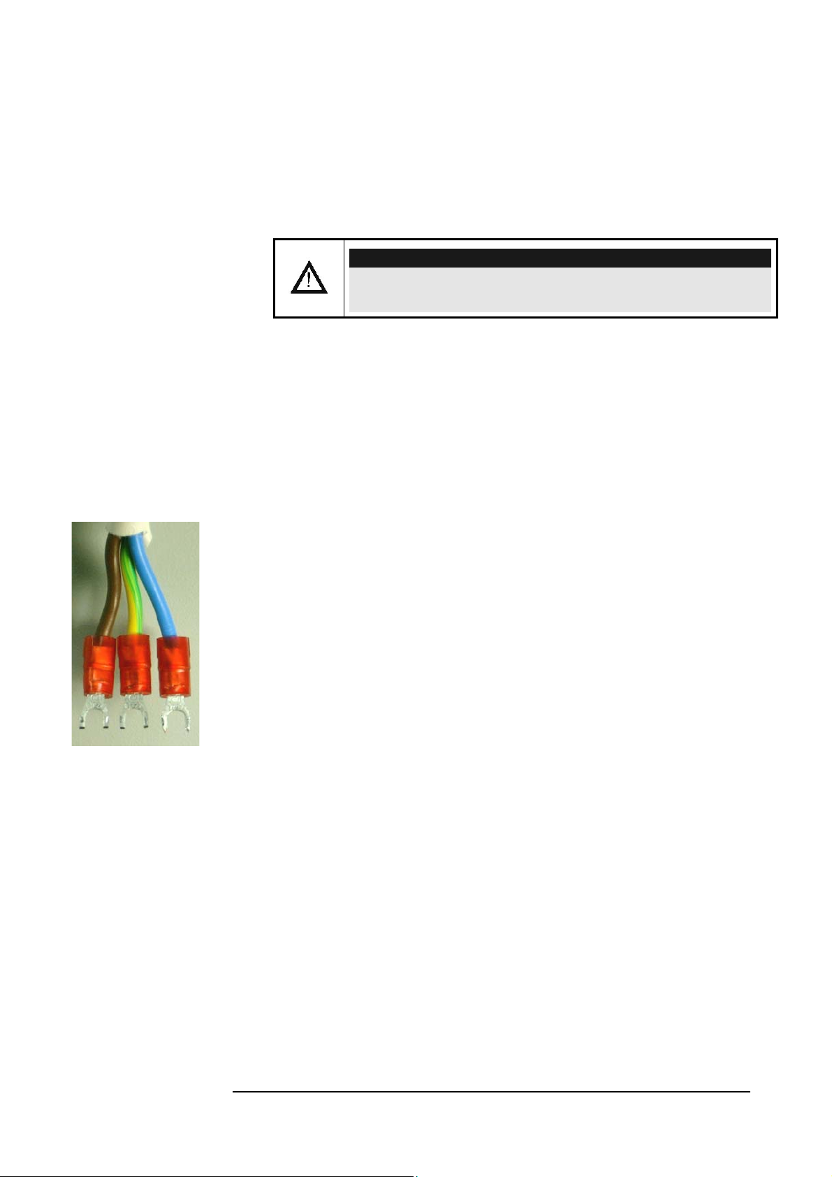
Figure A: 3 terminal cord forks
MRV Communications, Inc. – Installation Manual
Safety Requirements
All requirements stipulated in the safety laws of the country of installation must be
abided by when installing the TereScopes.
Caution!
In addition, ensure that the requirements noted in this chapter are met in
order to reduce risk of electrical shock and fire and to maintain proper
installation.
Before Installing
Power: Ensure that all power to the TereScope is cut off. Specifically,
disconnect all TereScope power cords from the power line (mains).
Inspection: Ensure by inspection that no part is damaged.
Before Powering On
Line Power: Ensure that the power from the line (mains) is as specified on
the TereScope.
Power Cord: The power cord of The TereScope must have the following
specifications:
Flexible 3-conductor power cord approved by the cognizant
safety organization of the country. The power cord must be
Type HAR (harmonized), with individual conductor wire
having cross-sectional area 0.75 sq. mm. min. The power cord
terminations should be a suitably rated earthing-type plug at
one end and 3 terminal cord forks for M3 screws (1 for each
wire) at the other end. Both of the power cord terminations
must carry the certification label of the cognizant safety
organization of the country.
When Installing
• Ensure, by visual inspection, that no part of the TereScope is damaged.
• Avoid eye contact with the laser beam at all times.
• Ensure that the system is installed in accordance with ANSI Z136.1
control measures (engineering, administrative, and procedural
controls).
• Ensure that the system is installed in accordance with applicable
building and installations codes.
• Install the TereScope in a restricted location as defined in this manual
since it is a Class 1M FSOCS transmitter and receiver. A restricted
location is a location where access to the transmission equipment and
exposed beam is restricted and not accessible to the general public or
iv
Page 10

MRV Communications, Inc. – Installation Manual
casual passerby. Examples of restricted locations are: sides of buildings
at sufficient heights, restricted rooftops, and telephone poles. This
definition of a restricted location is in accordance with the proposed
IEC 60825-I Part 12 requirements.
• Avoid using controls, adjustments, or procedures other than those
specified herein as they may result in hazardous radiation exposure.
• Avoid prolonged eye contact with the laser beam (maximum10 sec.).
• CAUTION-CLASS 3B LASER RADIATION WHEN OPEN
AVOID EXPOSURE TO THE BEAM
Servicing
All servicing must be carried out only by qualified service personnel. Before
servicing, ensure that all power to the TereScope is cut off!
v
Page 11
MRV Communications, Inc. – Installation Manual
Introduction
CAREFULLY READ THE ENTIRE
MANUAL BEFORE INSTALLING
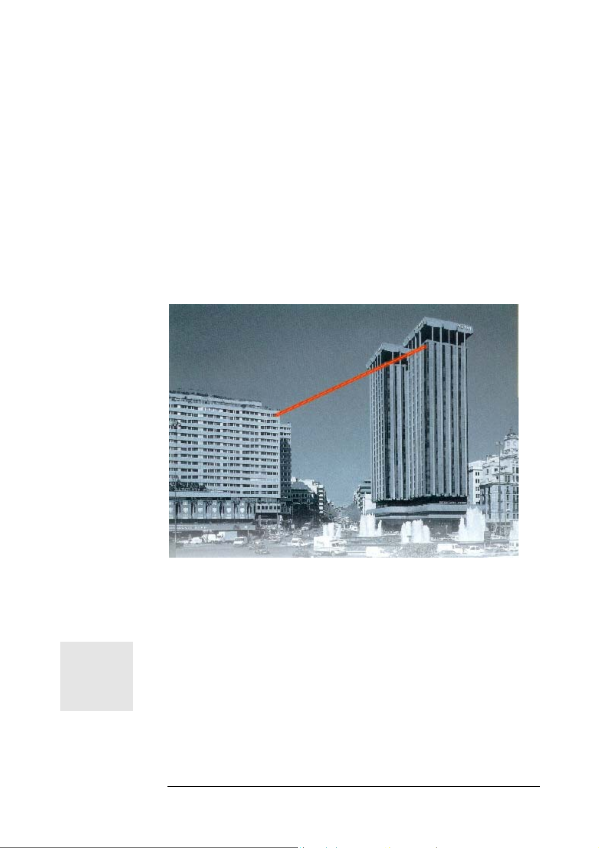
n InfraRed (IR) link allows connection without any cable between two
distant sites. For that, two identical transceivers, each installed on one site
A
other through the air over an optical wavelength carrier, the IR.
and aligned one facing each other, provide a point-to-point connectivity.
This configuration makes possible data transfer from one terminal to the
The installation of such a link can be summed up in 4 stages:
♦ Site survey
♦ Installation of the infrastructure
♦ Mounting of the equipment
♦ Aiming procedure
Always use appropriate safety equipment and
procedures when working with electrical
equipment and when working on roofs.
vi
Page 12

MRV Communications, Inc. – Installation Manual
The Product
Lift and hold the transceiver cautiously, taking care particularly
not to damage the front Polycarbonate window
Models
Table 1: Models of the TS50001
.
Chapter
Models Part Number Description
TS5000/G TS5000G/XYZ/V**
Standard Model
TS5000G/M8C/V1S
TS5000/G-F TS5000G/XYZ/F**
Standard Model
TS5000G/M8C/F1S
TereScope5000/G, 8 inch receiver Free
Space Optics 870m@30db/km and
3500m@3db/km (clear weather), Open
Protocol 100-1250Mbps with clock
recovery, visual alignment. XYZ coding:
interface options: M8C, M8T, S3C, S5C
(Standard model: TS5000G/M8C/V1S).
RCMU-SNMP included (Remote Control
and Management Unit), Removable
interface, Removable Power supply,
Redundant Power supply: Optional.
**Power supply options: 1S, 2S, 13, 23, 24
(See below for power supply options
explanation). Basic accessories kit supplied
with the link: AD-5000, JMP-8 and JITK
TereScope5000/G-F with buil-in Fusion, 8
inch receiver Free Space Optics
870m@30db/km and 3500m@3db/km
(clear weather), Open Protocol 1001250Mbps with clock recovery, visual
alignment. XYZ coding: interface options:
M8C, M8T, S3C, S5C (Standard model:
TS5000G/M8C/F1S). RCMU-SNMP
included (Remote Control and Management
Unit), Removable interface, Removable
Power supply, Redundant Power supply:
Optional. **Power supply options: 1S, 2S,
13, 23, 24 (See below for power supply
options explanation). Basic accessories kit
supplied with the link: AD-5000, JMP-8 and
JITK
1
TereScope 5000
1
Page 13

MRV Communications, Inc. – Installation Manual
TS5000/155 TS5000/XYZ/V**
Standard Model
TS5000/M3C/V1S
TS5000/155-F TS5000/XYZ/F**
Standard Model
TS5000/M3C/F1S
TereScope5000/155, 8 inch receiver Free
Space Optics 1185m@30db/km and
5400m@3db/km (clear weather), Open
Protocol 1-155Mbps, Selectable Protocols 34155Mbit/s, visual alignment. XYZ coding:
interface options: M3C, M3T, S3C, S5C
(Standard model: TS5000/M3C/V1S).
RCMU-SNMP included (Remote Control and
Management Unit), Removable interface,
Removable Power supply, Redundant Power
supply: Optional. **Power supply options: 1S,
2S, 13, 23, 24 (See below for power supply
options explanation). Basic accessories kit
supplied with the link: AD-5000, JMP-8 and
JITK.
TereScope5000/155-F with buit-in Fusion, 8
inch receiver Free Space Optics
1185m@30db/km and 5400m@3db/km
(clear weather), Open Protocol 1-155Mbps,
Selectable Protocols 34-155Mbit/s, visual
alignment. XYZ coding: interface options:
M3C, M3T, S3C, S5C (Standard model:
TS5000/M3C/F1S). RCMU-SNMP included
(Remote Control and Management Unit),
Removable interface, Removable Power
supply, Redundant Power supply: Optional.
**Power supply options: 1S, 2S, 13, 23, 24 (See
below for power supply options explanation).
Basic accessories kit supplied with the link:
AD-5000, JMP-8 and JITK.
TS5000/ETH TS5000/ETH/V*
TS5000/4U1 TS5000/4U1/V*
TereScope5000/ETH, 8 inch receiver Free
Space Optics 1400m@30db/km and
6700m@3db/km (clear weather),
ETHERNET Link, 10 Mbit/s, (RJ45), visual
alignment. RSM-SNMP included, Removable
Power supply, Power supply S or 3 (See below
for power supply options explanation). Basic
accessories kit supplied with the link: AD5000, JMP-8 and JITK.
TereScope5000/4E1 or
TereScope5000/4T1 Free Space
1400m@30db/km and 6700m@3db/km
(clear weather), 4E1 Link, G.703/G.704, and
Interface: 4 Universal connectors to be used
with 75 Ohm (Coax) or 120 Ohm (STP),
visual alignment. RSM-SNMP included,
Removable Power supply, Power supply S or
3 (See below for power supply options
explanation). Basic accessories kit supplied
with the link: AD-5000, JMP-8 and JITK.
Using the Part Number for Ordering
To place an order for a TS5000 model having a specific configuration, use the
Part Number format shown in Table 1, noting the following:
In 155 Series the ‘155’ is omitted in the part number, the absence of "155"
represents link operation speed in the range 1 to 155 Mbps.
‘G’ represents link operation speed in the range 100 to 1250 Mbps.
‘ETH’ represents 10 Mbps (Ethernet) operation speed.
‘X’ represents Optical Fiber Mode.
Instead of X use one of the following:
2
Page 14
MRV Communications, Inc. – Installation Manual
M (for Multimode)
S (for Single Mode)
‘Y’ represents operating wavelength.
Instead of Y use one of the following:
8 (for 850 nm)
3 (for 1310 nm)
5 (for 1550 nm)
‘Z’ represents connector type.
Instead of Z use one of the following:
C (for SC)
T (for ST)
‘V’ represents yes or not with Fusion.
Instead of V use one of the following:
V represents no built-in Fusion option.
F represents built-in Fusion option.
Power Supply
: Each product base code ends with * or **. * means that the
product has one power supply. **means that the product can have two power
supplies: one main and the other one - for back-up. In the products description,
there is a list of all compatible power supplies. When ordering, please specify the
required power supply and make sure that it is in the above list. For example, if a
TS5000/155 with one power supply, high voltage (100-240VAC) is required;
TS5000/XYZ/V1S should be ordered. Similarly, in case of 2 power supplies low
voltage (35-60VDC), the p/n will be TS5000/XYZ/V23. If the required product
can have only one power supply, for example TS5000/ETH, high voltage, the
p/n will be TS5000/ETH/VS.
‘S’ represents power supply type
Instead of S use one of the following:
S (for input to the power supply in the range 100-240 VAC)
3 (for input to the power supply in the range 35-60 VDC)
‘U’ represents telephony protocol type.
Instead of U use one of the following:
E (for E1)
T (for T1)
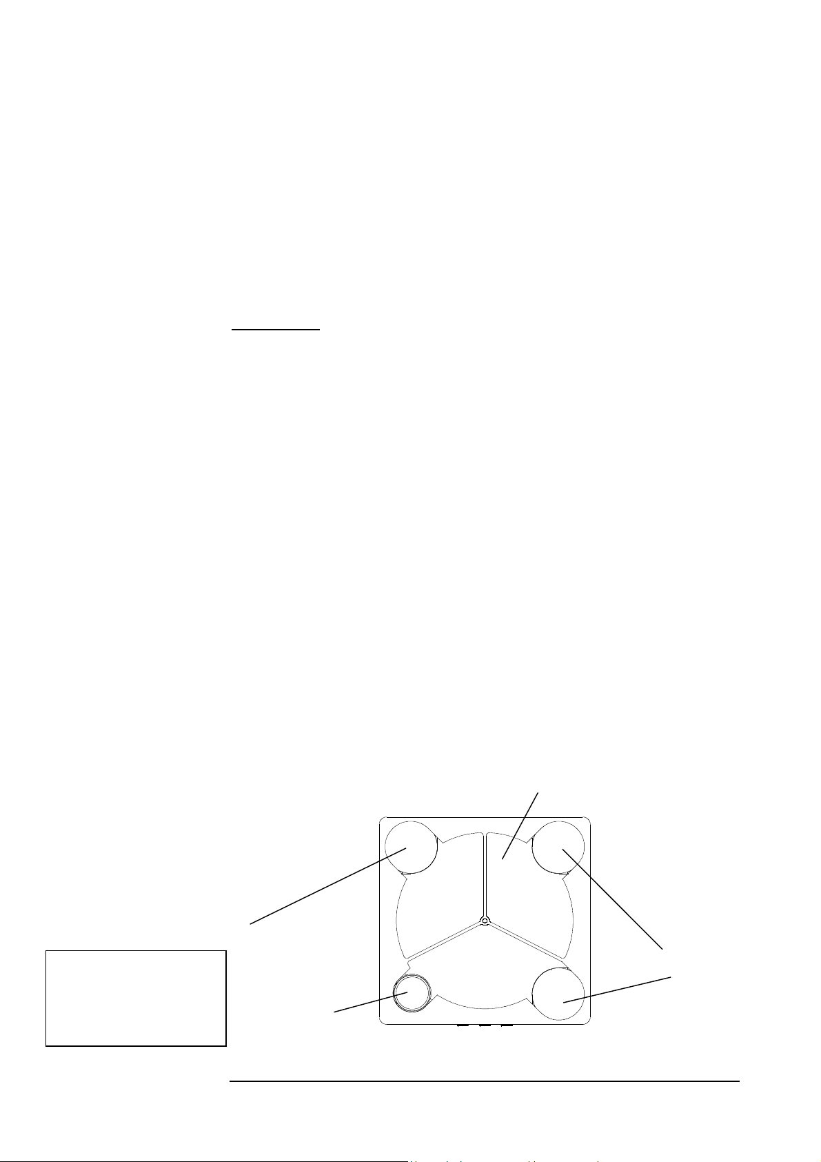
Front view
Showing the receiver
side, the transmitters and
the telescope
Transmitter
CAUTION!
AVOID EXPOSURE –
INVISIBLE LASER
RADIATION IS EMITTED
FROM THIS APERTURE
General Description
1. Front
Each unit comprises a receiver, 3 transmitters and an interface on the rear panel for
the connection to the peripheral equipment.
Transmitters
Telescope
Figure 1.1: Front View Schematic
3
Page 15
MRV Communications, Inc. – Installation Manual
2. Back
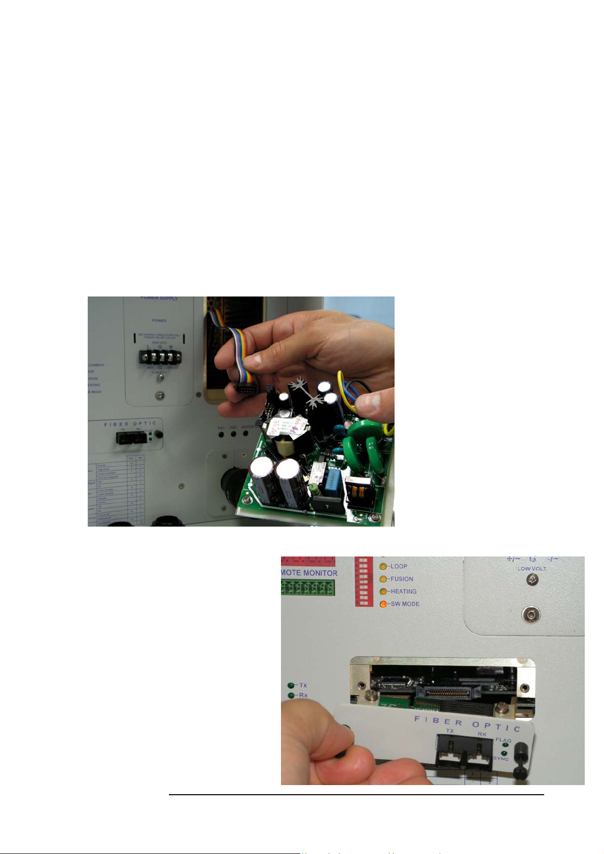
The TS5000 has a pluggable power supply. In the field, a failed power supply can
be replaced within seconds without the need for performing any other changes to
the TS5000. Appendix I gives the procedure for replacing the power supply.
All models of the TS5000 are SNMP manageable. SNMP monitoring can be
performed using MRV’s MegaVision SNMP management server application.
TS5000/G and TS5000/155
There have been several additional improvements to the TS5000/G and
TS5000/155 models:
An additional optional power supply, i.e. a standard model has one
modular power supply and a redundant power supply can be ordered
or even added in the field. (fig 1.2a)
The interface of these models is modular as well. (Fig. 1.2b)
A new SNMP Management card. See Appendix J: "TS5000 & TS4000
enhancements" for further info on the improvements to these models.
Figure 1.2a: Connecting the
redundant Power supply
Figure 1.2b: Changing the Optical
interface
4
Page 16
A
V
p
N
ot in use
MRV Communications, Inc. – Installation Manual
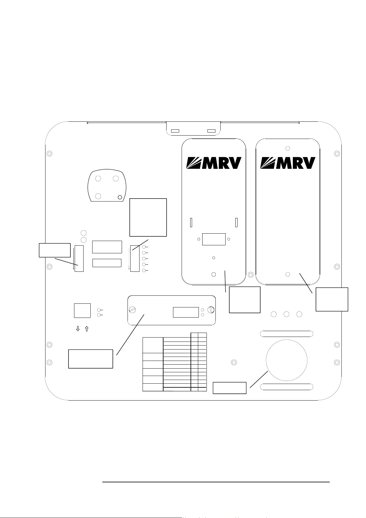
A. TS5000/G Standard Model (w/o Fusion and with one power supply)
The TS5000/G can support various data rates and protocols within the 20Mbps -
1.5 Gbps range, for example Fast Ethernet, ATM, 622 Mbps, Fiber Channel,
Gigabit Ethernet, etc. The TS5000/G has Clock Recovery for the entire operation
range. There is no need to set the clock by means of DIP switches or other means.
The TereScope automatically identifies and locks on to the clock frequency of the
transferred data
LASERS STATUS
(BACK VIEW)
L 2 ONL 1 ON
L 3 ON
TELESCOPE
AIR RX
FLAG
SYNC
1
10 10
DS 1
OPTICAL POWER
REMOTE MONITOR
DIP Switch
Toggles 4, 7
and 9
ositions are
immaterial.
1
DS 2
ALIGNMENT
LOOP
FUSION
HEATING
SW MODE
POWER SUPPLYPOWER SUPPLY
DISCONNECT POWER SUPPLY
FROM MAINS
BEFORE REMOVAL FROM UNIT
POWERPOWER
USE COPPER CONDUCTORS ONLYUSE COPPER CONDUCTORS ONLY
TORQUE VALUE 7 Lb-InchTORQUE VALUE 7 Lb-Inch
HIGH HIGH VOLT.
OLT.
L L
G G GGN N
+/~+/~
-/~-/~
LOW LOW VOLT.VOLT.
REDUNDANT
POWER SUPPLY
This slot can
house an additiona l
power supply
to be fed
from backup
voltage source.
This can be
independent
of the primary
voltage source for
maximum redundanc y.
For details:
Contact an authorized
MRV representative
or visit www.mrv.com
MANAGEMENT
Rx
Tx
3-6
1-2
Pluggable
interface
1766240
INVISIBLE LASER RADIATION IS EMITTED FROM THIS APERTURE
Tx
Rx
TABLE FOR DS 2
Mode Select
Attenuation for
Short Di stance Li nk
Fusion
Window Heater
(if exist)
IP Address Setup
Control Mode
VOID EXPOSURE
F I B E R O P T I C
TX RX
Normal
Alignment
Local Loopback
Remote Loopback
Normal
Attenuated
Disable
Enable
Off
On
Default IP
Software IP
HW MODE
SW MODE
FLAG
SYNC
OFF
ON
-
1,2
1 2
2
1
-
1,2
-
3
-
3
5
-
-
5
-
6
-
6
-
8
-
8
-
10
-
10
Pluggable
Power
Supply
CAUTION
DO NOT USE
TELESCOPE
TO LIFT UNIT ! !
Telescope
PS1
PS2 HEATER ON
Slot for
Redundant
PS
Figure 1.3: TS5000/G Standard Model Panel Schematic
5
Page 17

MRV Communications, Inc. – Installation Manual
Back Panel Description
Table 2: TS5000/G Back Panel Controls, Interfaces, and Indicators
Power
Connectors
Power source Terminal Block (Main or UPS).
AC power supply (100 to 240 Vac) or DC power
supply (35 to 60 Vdc)
Fiber optic
Remote Monitor Connection to an optional Remote Status Monitor
Management
Fiber Optic interface for connection to the
peripheral equipment. The standard interface is MM
850nm SC connector; other interfaces are available
upon request (refer to price list or data sheet).
In model TS5000/G-F with the fusion option, there
are two fiber optic interface ports for connection to
the Fusion system; one primary and the other
redundant.
(RSM) or to RSM-DC (for Dry Contact connection)
(not included in the standard transceiver kit)
Connection to 10Base-T SNMP management
interface. Pins 1,2: TX and 3,6 RX.
Pins (4,5) and (7,8) of this connector can be used for
dry contact purposes, for Airlink flag and F/O flag
alarms respectively
Note:
Pins (4, 5) and (7, 8) of the management RJ45 connector can be used for dry contact
purposes, for Airlink flag and F/O flag alarms respectively.
Alignment Telescope
Power
Power Supply
Slot for Power Supply
For fine alignment.
Pluggable AC power supply (100 to 240 Vac) or
DC power supply (35 to 60 Vdc)
This slot can house an additional power supply to
be fed from backup voltage source. This can be
independent of primary voltage source for
maximum redundancy.
6
Page 18

MRV Communications, Inc. – Installation Manual
Selectors
(DIP Switch
DS1 Toggles)
-- shown on
Figure 1.3and
1.4
Selectors
(DIP Switch
DS2 Toggles)
-- shown on
Figure 1.3 and
1.4
Not in use Not in use
Mode Select
(Toggles 1, 2)
Set the Operating Mode
ALIGNMENT = Idle transmitted automatically
NORMAL
transmitted through the Airlink TX. Signal received
via the Airlink RX is transmitted through the F/O
TX.
LOOPBACK
directly returned through the F/O TX.
REMOTE LOOP
electrical TX and optical RX to the optical TX of the
remote unit.
Attenuation for
Short distance link
(Toggle 3)
Turning off 1 TX when the DIP switch toggle is
moved to ON. (The LED L1 will turn off also).
Use this option for distances between 500 and 700m
Fusion
(Toggle 5)
This switch toggle enables working with MRV’s
Fusion system (Built-in fusion option or switch
option). For additional information, see page 9.
Switch toggle 5 OFF: Fusion not Active (Disabled)
Switch toggle 5 ON: Fusion active (Enabled).
Window Heater
(Optional)
(Toggle 6)
Used only with the heating option (To be specified
in the PO).
Switch toggle 6 OFF: The heater is disabled
Switch toggle 5 ON: The heater is enabled.
The heating will start operating only if one of the
following conditions is present: or the temperature is
lower than 15
above 80%. There is a controller with a thermostat
inside the TereScope, which controls the heating in
accordance with the above conditions.
IP address set up
(Toggle 8)
When the Switch toggle is on OFF position, the
TereScope’s IP address is the default one (shown on
the back panel label: 10.0.0.101). To set a new IP
address, please refer to the “IP address setting
procedure for TereScope management card” file in
the Manuals CD. The new IP address is valid only
after the TereScope is powered off and on.
Control Mode
(Toggle 10)
When the Dip Switch toggle #10 is on OFF
position, the TereScope is in the HARDWARE
mode, i.e. the TereScope is controlled only by the
TereScope itself by means of the switches on its
back panel.
When the Dip Switch toggle is on ON position, the
TereScope is in the SOFTWARE mode i.e. the
TereScope is controlled by the management
Software and various functions can be activated by
means of this management Software.
= Signal received via the F/O port is
= Data received by the F/O RX is
= Loops the electrical RX to the
o
C; or the humidity level in the air is
7
Page 19

MRV Communications, Inc. – Installation Manual
Indicators
(7-segment
display and
LEDs)
Air RX Flag LED Green LED indicates data received by the Airlink
receiver. Turns ON at the threshold level.
Air RX Sync LED Yellow LED. Turns ON if the rate of the received
Data matches the Data Rate set on the Data Rate
DIP switch.
F/O Main, RX Flag
LED
Upper green LED indicates Data received by the
Fiber Optic receiver. Turns ON at the threshold
level.
F/O Main, RX Sync
LED
Lower green LED. Turns ON if the rate of the
received Data matches the Data Rate set on the
Data Rate DIP switch.
F/O Redundant, RX
Flag LED
(Optional)
Upper green LED indicates Data received by the
Fiber Optic receiver. Turns ON at the threshold
level.
F/O Redundant, RX
Sync LED
(Optional)
Lower green LED. Turns ON if the Fusion is
active and there is synchronization with the
received Data.
Optical Power 7segment display
Digital readout indicates the Optical Power level
received by the Airlink receiver.
Alignment LED Yellow LED. Turns ON if the Alignment
Operating Mode is selected.
Loop LED Yellow LED. Turns ON in LOOPBACK mode.
Flashing in Remote Loop mode.
Fusion LED Yellow LED. Turns ON if the Fusion mode is
enabled.
Flashing when the Fusion (radio back-up system) is
active.
Heating LED Yellow LED. Turns ON if the heating mode is
selected (Heating is enabled).
SW Mode LED Red LED. Turns ON if the SW Mode
(SOFTWARE) Operating Mode is selected.
Lasers status LEDs There are 3 LEDs – L1, L2, L3 indicating if the
lasers are switched on or off. If the LED is
switched off, the laser is switched off. If the LED is
switched ON, the laser is switched ON.
When the DIP switch toggle #3 is moved to ON
position the LED L1 and its corresponding laser
will turn off
PS1 Green LED. Turns ON when main power supply is
active
PS2 Green LED. Turns ON when redundant power
supply is active
Heater ON Green LED. Turns ON when the heating of the
front window is active.
The heating will start operating only if one of the
following conditions is present: or the temperature
is lower than 15
o
C; or the humidity level in the air is
above 80%. There is a controller with a thermostat
inside the TereScope, which controls the heating in
accordance with the above conditions. (The heating
option is not standard, and exists only if purchased)
Management TX Flashing when the RSM-SNMP is connected and
the TereScope is transmitting management Data.
(There is no Link indication)
Management RX Flashing when the RSM-SNMP is connected and
the TereScope is receiving management Data.
(There is no Link indication)
8
Page 20
MRV Communications, Inc. – Installation Manual
A
N
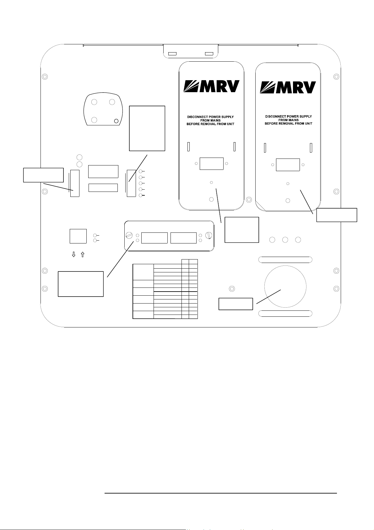
B. TS5000/G-F (Standard Model including Fusion option)
LASERS STATUS
(BACK VIEW)
L 2 ONL 1 ON
ot in use
L 3 ON
AIR RX
FLAG
SYNC
1
MANAGEMENT
DS 1
Tx
1-2
Rx
3-6
OPTICAL POWER
REMOTE MONITOR
Pluggable
interface, with
Fusion option
1766240
Tx
Rx
TELESCOPE
DIP Switch
Toggles 4,
7 and 9
positions
are
immaterial.
1
1010
ALIGNMENT
LOOP
FUSION
HEATING
SW MODE
DS 2
VOID EXPOSURE
INVISIBLE LASER RADIATION IS EMITTED FROM THIS APERTURE
INVISIBLE LASER RADIATION IS EMITTED FROM THIS APERTURE
FLAG FLAG
SYNC SYNC
Mode Select
Attenuation for
Short Di stance Link
Fusion
Window Heater
(if exist)
IP Address Setup
Control Mode
AVOID EXPOSURE
F I B E R O P T I C
REDUNDANT
TX RX
FOR FUSION
TABLE FOR DS 2
Normal
Alignment
Local Loopback
Remote Loopback
Normal
Attenuated
Disable
Enable
Off
On
Default IP
Software IP
HW MODE
SW MODE
TX RX
POWER SUPPLY
USE COPPER CONDUCTORS ONLY
TORQUE VALUE 7 Lb-Inch
L
+/~
MAIN
OFF
ON
-
1,2
1 2
1
2
-
1,2
3
-
-
3
5
-
-
5
-
6
-
6
-
8
-
8
-
10
-
10
POWER
HIGH VOLT.
G GN
-/~
LOW VOLT.
Telescope
Pluggable
Power
Supply
CAUTION
DO NOT USE
TELESCOPE
TO LIFT UNIT ! !
POWER SUPPLY
POWER
USE COPPER CONDUCTORS ONLY
TORQUE VALUE 7 Lb-Inch
HIGH VOLT.
G
L
+/~
PS1 PS2 HEATER ON
G
LOW VOLT.
N
-/~
Redundant PS
Figure 1.4: TS5000/G-F with a redundant power supply Panel Schematic
This special TS5000/G-F model can be connected to the back-up radio system
without special MRV’s Switch and card supporting Fusion. This TereScope
can be connected to any Giga-Switch with
1000Base-SX port, which should
be connected to the optical port of the TereScope labeled “Redundant”, while
the back-up radio system is connected to the 10Base-T port of the same
Switch.
For more details please see pages 15 and 16
9
Page 21
MRV Communications, Inc. – Installation Manual
V
LASERS STATUS
(BACK VIEW)
L 2 ONL 1 ON
L 3 ON
TELESCOPE
AIR RX
FLAG
SYNC
1
10
MANAGEMENT
TABLE FOR DS 1
Data Rate
1766240
OPTICAL POWER
REMOTE MONITOR
DS 1 DS 2
Tx
Rx
Tx
3-6
1-2
Fast Ethe rnet 100M bps
ATM/OC3/STM1: 155Mbps
SMPTE: 143 Mbps
E3: 34.368 Mbps
T3: 44.736 Mbps
OC1/STM0 : 51 .8 40 Mb ps
Customiz ed 1
Customiz ed 2
Open Protocol
Rx
OFF
1,2,3,4
2,3,4
3,4 1,2
1,2,4
2,4
1,4
4
1,3,4
1,2,3
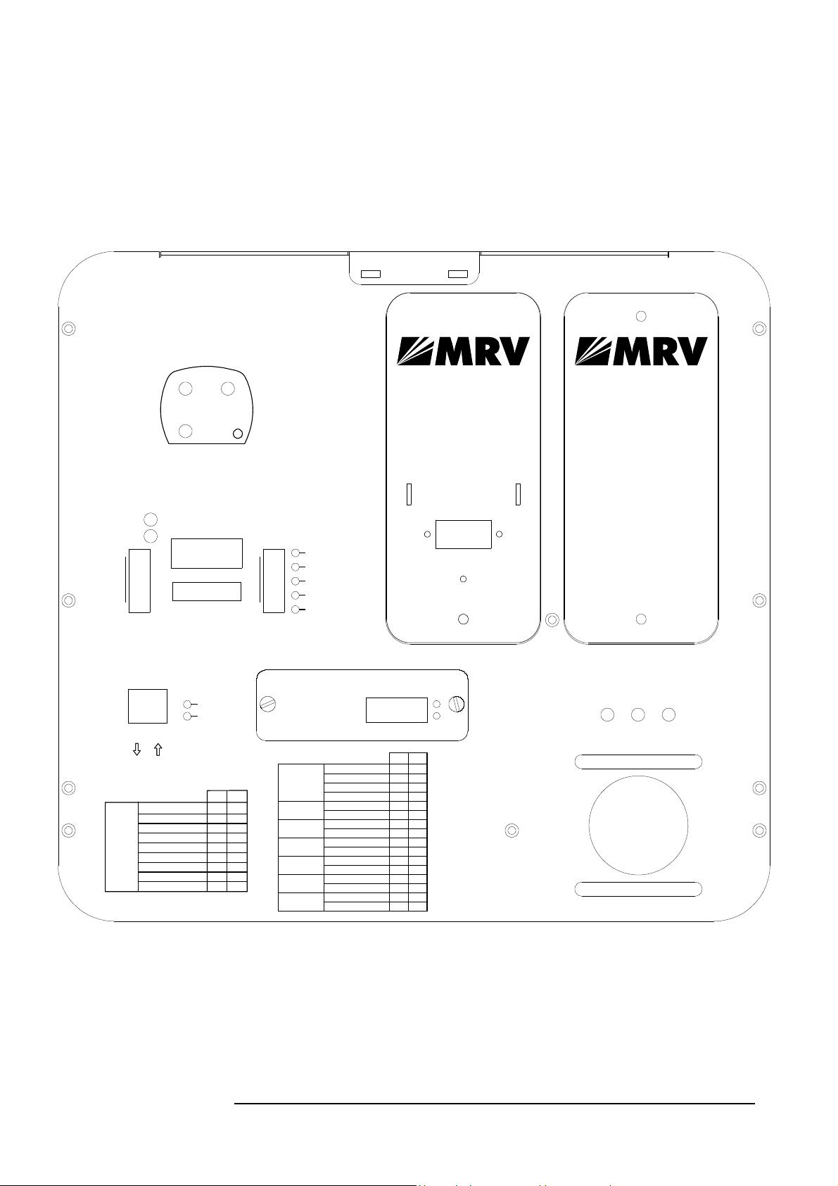
C. TS5000/155
(w/o Fusion and with one power supply)
The TS5000 supports most of the prevalent protocols in the 34-155 Mbps range.
Special protocol, which is not on the list, can be ordered after coordination with
the factory. This model can be used for Open Protocol applications, which
ensures complete transparency (including all data in the range of 1-155 Mbps.)
In this case maximum 2 dB of the performance is lost.
POWER SUPPLYPOWER SUPPLY
DISCONNECT POWER SUPPLY
FROM MAINS
BEFORE REMOVAL FROM UNIT
POWERPOWER
USE COPPER CONDUCTORS ONLYUSE COPPER CONDUCTORS ONLY
TORQUE VALUE 7 Lb-InchTORQUE VALUE 7 Lb-Inch
HIGH HIGH VOLT.
OLT.
L L
G G GGN N
1
10
ALIGNMENT
LOOP
FUSION
HEATING
SW MODE
+/~+/~
LOW LOW VOLT.VOLT.
-/~-/~
REDUNDANT
POWER SUPPLY
This slot can
house an additi ona l
power supply
to be fed
from backup
voltage source.
This can be
independent
of the primary
voltage so urce for
maximum redundancy.
For details:
Contact an authorized
MRV representative
or visit www.mrv.com
INVISIBLE LASER RADIATION IS EMITTED FROM THIS APERTURE
AVOID EXPOSURE
F I B E R O P T I C
TX RX
FLAG
SYNC
PS1 PS2 HEATER ON
ON
1,3
2,3
1,2,3
1
3
2
4
TABLE FOR DS 2
Mode Select
Alignment Signal
Attenuation
Laser Status
Fusion
Window Heater
(if exist)
IP Address Setup
Control Mode
Normal
Alignment
Local Loopback
Remote Loopback
Off
On
Laser Enable
Laser Disable
Disable
Enable
Off
On
Default IP
Software IP
HW MODE
SW MODE
OFF
ON
-
1,2
1 2
1
2
-
1,2
-
3
-
3
-
4
-
4
-
5
5
-
-
6
-
6
-
8
-
8
-
10
10
-
CAUTION
DO NOT USE
TELESCOPE
TO LIFT UNIT ! !
Figure 1.5: TS5000/155 Standard Model Panel Schematic
10
Page 22
MRV Communications, Inc. – Installation Manual
Back Panel Description
Table 3: TS5000/155 Back Panel Controls, Interfaces, and Indicators
Connectors
Power Power source Terminal Block (Main or UPS).
AC power supply (100 to 240 Vac) or DC power
supply (35 to 60 Vdc)
Fiber optic
Remote Monitor Connection to an optional Remote Status Monitor
Management
Fiber Optic interface for connection to the
peripheral equipment. The standard interface is MM
1310nm SC connector; other interfaces are available
upon request (refer to price list or data sheet).
In model TS5000/155-F with the fusion option,
there are two fiber optic interface ports for
connection to the Fusion system; one primary and
the other redundant.
(RSM) or to RSM-DC (for Dry Contact connection)
(not included in the standard transceiver kit)
Connection to 10Base-T SNMP management
interface. Pins 1,2: TX and 3,6 RX.
Pins (4,5) and (7,8) of this connector can be used for
dry contact purposes, for Airlink flag and F/O flag
alarms respectively
Note:
Pins (4, 5) and (7, 8) of the management RJ45 connector can be used for dry contact
purposes, for Airlink flag and F/O flag alarms respectively
Alignment Telescope
For fine alignment.
Power
Power Supply
Slot for Power Supply
Pluggable AC power supply (100 to 240 Vac) or
DC power supply (35 to 60 Vdc)
This slot can house an additional power supply to
be fed from backup voltage source. This can be
independent of primary voltage source for
maximum redundancy.
.
11
Page 23

MRV Communications, Inc. – Installation Manual
Selectors
(DIP Switch
DS1 Toggles)
---shown on
Figures 1.5and
1.6
Selectors
(DIP Switch
DS2 Toggles)
-- shown in
Figures 1.5 and
1.6
Data Rate
(Toggles 1, 2, 3 and
4)
Mode Select
(Toggles 1, 2)
Alignment Signal
Attenuation
(Toggle 3)
Laser Status
(Toggle 4)
Fusion
(Toggle 5)
Window Heater
(Optional)
(Toggle 6)
IP address set up
(Toggle 8)
Control Mode
(Toggle 10)
Set the transmission rate of the transceiver (internal
clock).
- Fast Ethernet: 1,2,3,4 OFF
- ATM/OC3/STM1: 155 Mbps: 2,3,4 OFF, 1 ON
- SMPTE 143 Mbps: 3,4 OFF, 1,2 ON
- E3: 34.368 Mbps 1,2,4 OFF, 3 ON
- T3: 44.736 Mbps: 2,4 OFF, 1,3 ON
- OC1/STM0: 51.840 Mbps: 1,4 OFF, 2,3 ON
- Customized 1 : 4 OFF, 1,2,3 ON
- Customized 2 : 1,3,4 OFF, 2 ON
- Open Protocol: 1, 2, 3 OFF, 4 ON.
Set the Operating Mode
ALIGNMENT = Idle transmitted automatically
NORMAL
= Signal received via the F/O port is
transmitted through the Airlink TX. Signal received
via the Airlink RX is transmitted through the F/O
TX.
LOOPBACK
= Data received by the F/O RX is
directly returned through the F/O TX.
REMOTE LOOP
= Loops the electrical RX to the
electrical TX and optical RX to the optical TX of the
remote unit.
ATTENUATION: The alignment signal is
attenuated (~20db) when the DIP switch toggle #3
is moved to ON position.(to use when the
installation distance is less than 900m only for
alignment mode). Switch back to OFF position for
normal mode.
Turning off TXs lasers when the DIP switch toggle
#4 is moved to ON
This switch toggle enables working with MRV’s
Fusion system (Built-in fusion option or switch
option). For additional information, see page 14.
Switch toggle 5 OFF: Fusion not Active (Disabled)
Switch toggle 5 ON: Fusion active (Enabled).
Used only with the heating option (To be specified
in the PO).
Switch toggle 6 OFF: The heater is disabled
Switch toggle 5 ON: The heater is enabled.
The heating will start operating only if one of the
following conditions is present: or the temperature is
o
lower than 15
C; or the humidity level in the air is
above 80%. There is a controller with a thermostat
inside the TereScope, which controls the heating in
accordance with the above conditions.
When the Switch toggle is on OFF position, the
TereScope’s IP address is the default one (shown on
the back panel label: 10.0.0.101). To set a new IP
address, please refer to the “IP address setting
procedure for TereScope management card” file in
the Manuals CD. The new IP address is valid only
after the TereScope is powered off and on.
When the Dip Switch toggle #10 is on OFF
position, the TereScope is in the HARDWARE
mode, i.e. the TereScope is controlled only by the
TereScope itself by means of the switches on its
back panel.
When the Dip Switch toggle is on ON position, the
TereScope is in the SOFTWARE mode i.e. the
TereScope is controlled by the management
Software and various functions can be activated by
means of this management Software.
12
Page 24

MRV Communications, Inc. – Installation Manual
Indicators
(7-segment
display and
LEDs)
Air RX Flag LED Green LED indicates data received by the Airlink
receiver. Turns ON at the threshold level.
Air RX Sync LED Yellow LED. Turns ON if the rate of the received
Data matches the Data Rate set on the Data Rate
F/O Main, RX Flag
LED
DIP switch.
Upper green LED indicates Data received by the
Fiber Optic receiver. Turns ON at the threshold
level.
F/O Main, RX Sync
LED
Lower green LED. Turns ON if the rate of the
received Data matches the Data Rate set on the
Data Rate DIP switch.
F/O Redundant, RX
Flag LED
(Optional)
Upper green LED indicates Data received by the
Fiber Optic receiver. Turns ON at the threshold
level.
F/O Redundant, RX
Sync LED
(Optional)
Lower green LED. Turns ON if the Fusion is
active and there is synchronization with the
received Data.
Optical Power 7segment display
Digital readout indicates the Optical Power level
received by the Airlink receiver.
Alignment LED Yellow LED. Turns ON if the Alignment
Operating Mode is selected.
Loop LED Yellow LED. Turns ON in LOOPBACK mode.
Flashing in Remote Loop mode.
Fusion LED Yellow LED. Turns ON if the Fusion mode is
enabled.
Flashing when the Fusion (radio back-up system) is
active.
Heating LED Yellow LED. Turns ON if the heating mode is
selected (Heating is enabled).
SW Mode LED Red LED. Turns ON if the SW Mode
(SOFTWARE) Operating Mode is selected.
Lasers status LEDs There are 3 LEDs – L1, L2, L3 indicating if the
lasers are switched on or off. If the LED is
switched off, the laser is switched off. If the LED is
switched ON, the laser is switched ON.
When the DIP switch toggle #3 is moved to ON
position the LED L1 and its corresponding laser
will turn off
PS1 Green LED. Turns ON when main power supply is
active
PS2 Green LED. Turns ON when redundant power
supply is active
Heater ON Green LED. Turns ON when the heating of the
front window is active.
The heating will start operating only if one of the
following conditions is present: or the temperature
is lower than 15
o
C; or the humidity level in the air is
above 80%. There is a controller with a thermostat
inside the TereScope, which controls the heating in
accordance with the above conditions. (The heating
option is not standard, and exists only if purchased)
Management TX Flashing when the RSM-SNMP is connected and
the TereScope is transmitting management Data.
(There is no Link indication)
Management RX Flashing when the RSM-SNMP is connected and
the TereScope is receiving management Data.
(There is no Link indication)
13
Page 25
MRV Communications, Inc. – Installation Manual
D. TS5000/155-F (Standard Model including Fusion option)
LASERS STATUS
(BACK VIEW)
L 2 ONL 1 ON
L 3 ON
TELESCOPE
AIR RX
FLAG
SYNC
1
OPTICAL POWER
REMOTE MONITOR
10
DS 1 DS 2
MANAGEMENT
Rx
Tx
3-6
1-2
Tx
Rx
OFF
1,2,3,4
2,3,4
3,4 1,2
1,2,4
2,4
1,4
4
1,3,4
1,2,3
Data Rate
1766240
TABLE FOR DS 1
Fast Ethernet 100Mbps
ATM/OC3/STM1: 155Mbps
SMPTE: 143 Mbps
E3: 34.368 Mbps
T3: 44.736 Mbps
OC1/STM0 : 51.8 40 Mbps
Customized 1
Customized 2
Open Protocol
ON
1,3
2,3
1,2,3
POWER SUPPLY
POWER
USE COPPER CONDUCTORS ONLY
TORQUE VALUE 7 Lb-Inch
HIGH VOLT.
L
G
N
1
10
1
3
2
4
ALIGNMENT
LOOP
FUSION
HEATING
SW MODE
INVISIBLE LASER RADIATION IS EMITTED FROM THIS APERTURE
FLAG FLAG
SYNC SYNC
Mode Select
Alignment Signal
Attenuation
Laser Status
Fusion
Window Heater
(if exist)
IP Address Setup
Control Mode
AVOID EXP OSU RE
F I B E R O P T I C
REDUNDANT
TX RX
FOR FUSION
TABLE FOR DS 2
Normal
Alignment
Local Loopback
Remote Loopback
Off
On
Laser Enable
Laser Disable
Disable
Enable
Off
On
Default IP
Software IP
HW MODE
SW MODE
MAIN
TX RX
OFF
1,2
1
3
-
4
5
-
6
-
8
-
10
-
ON
-
1 2
2
1,2
3
4
5
-
6
8
-
10
+/~
G
LOW VOLT.
-/~
CAUTION
DO NOT USE
TELESCOPE
TO LIFT UNIT ! !
POWER SUPP LY
POWER
USE COPPER CONDUCTORS ONLY
TORQUE VALUE 7 Lb-Inch
HIGH VOLT.
G
L
+/~
PS1 PS2 HEATER ON
G
LOW VOLT.
N
-/~
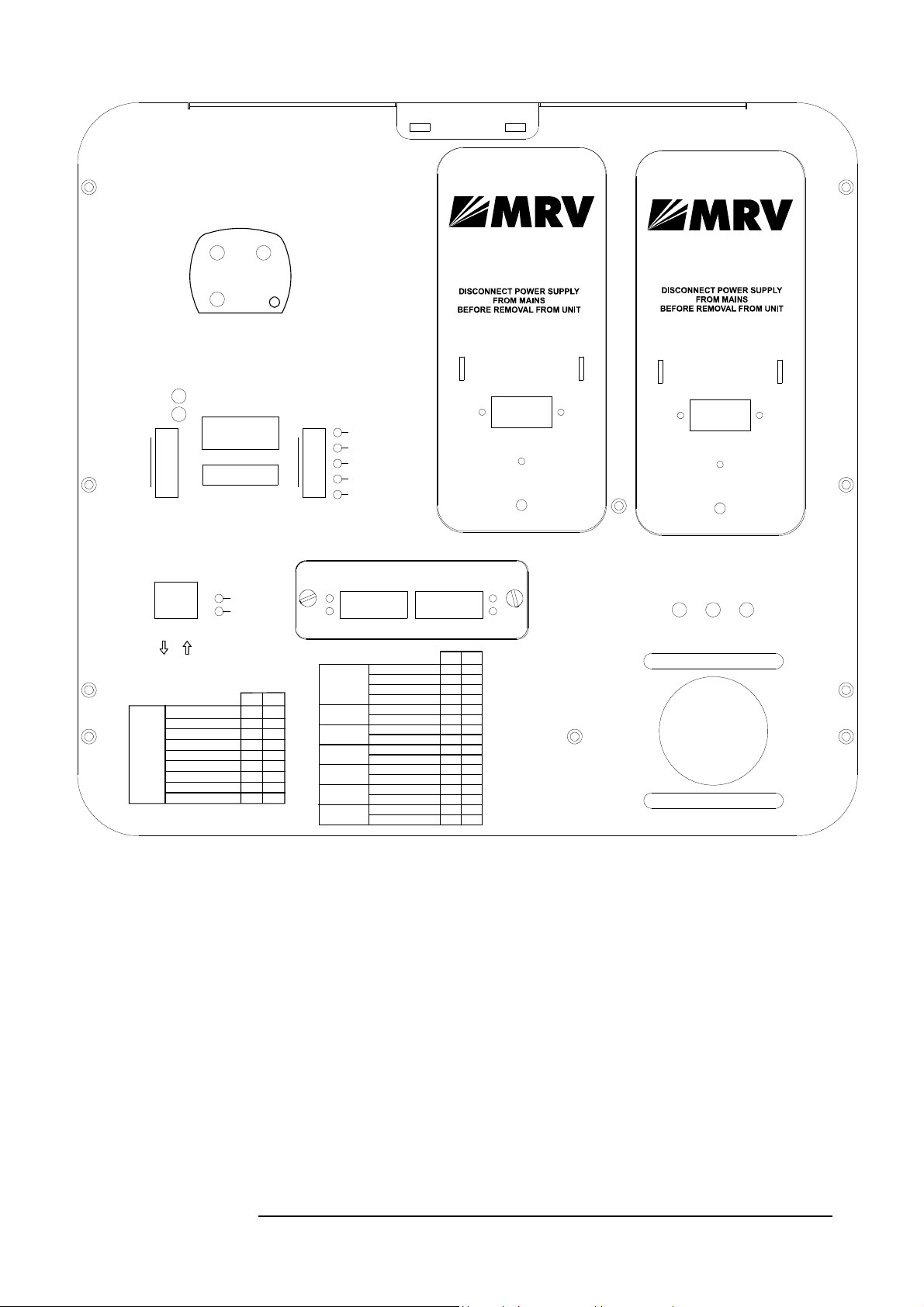
Figure 1.6: TS5000/155-F with a redundant power supply Panel Schematic
This special TS5000/155-F model can be connected to the back-up radio
system without special MRV’s Switch and card supporting Fusion. This
TereScope can be connected to any Switch (supporting 10/100) via standard
converter, which should be connected to the optical port of the TereScope
labeled “Redundant”, while the back-up radio system is connected to the same
Switch.
The TereScope can be also directly connected to MC (Media Converter) of the
type 10/100 TX-100 FX (for example MRV’s media converter MC102F).
When the TereScope stops operating, the connectivity from the main optical
module to the air channel stops and starts flowing into the second optical
module designated for radio.
14
Page 26
MRV Communications, Inc. – Installation Manual
That’s what
happens when
the air channel
stops
Main
F/O
Network
RF Transceiver
F/O
Redundant
10/100TX-100FX
Media Converter
IR = 100 Mbps or 1.25Gbps
RF = 2-10 Mbps
Or 100Mbps
TS
Redundant
Main
F/O
F/O
RF Transceiver
10/100 BaseT
STP
Switch
10/100 BT
MC
Network
10/100 BaseT
STP
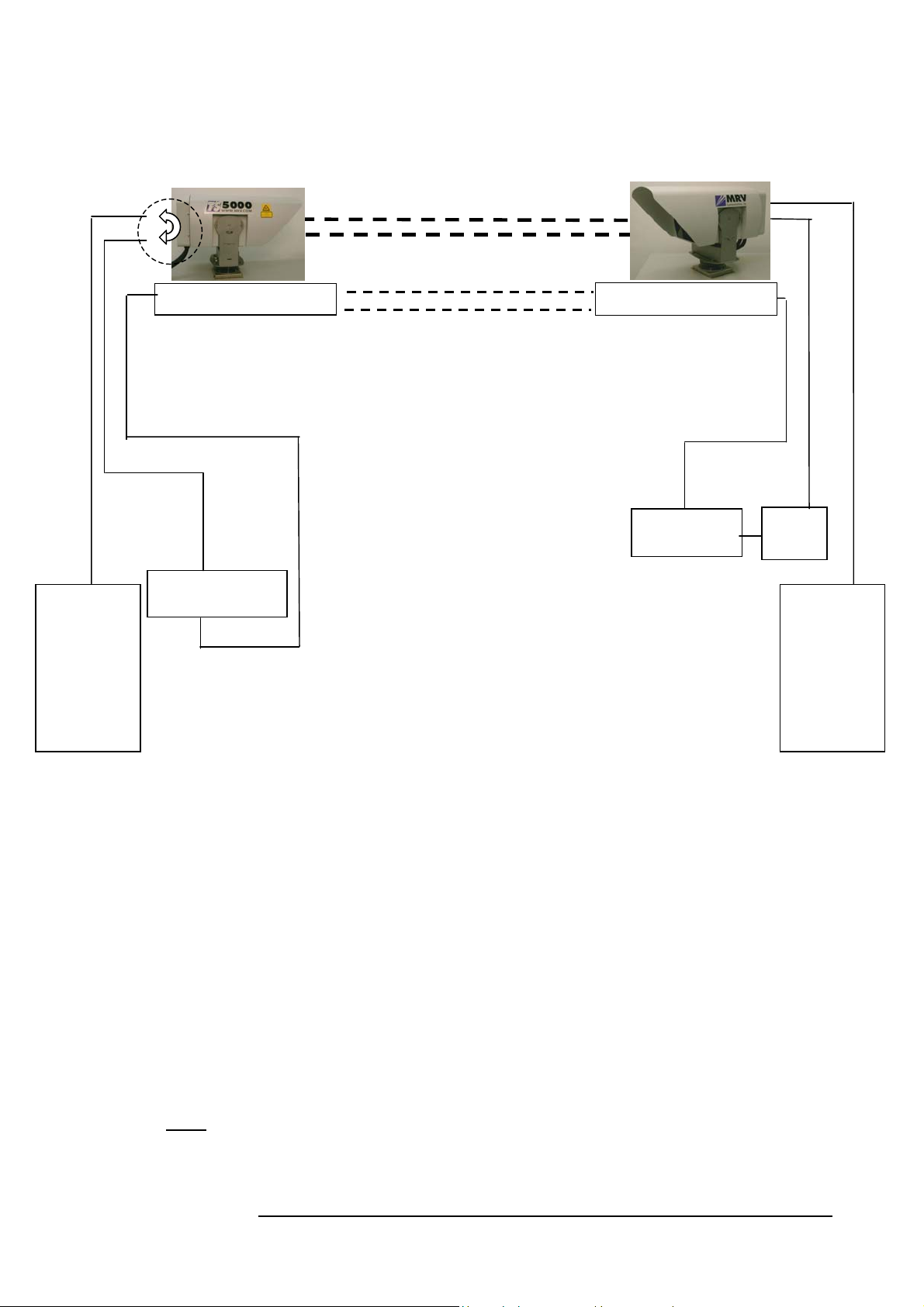
Figure 1.7a: TS5000/155-F or TS5000/G-F & Fusion Connections
For Description of the Back Panel and all the functions see Paragraph B for TS5000/G-F and
paragraph D for TS5000/155-F, Figure 1.4 or 1.6 – TS5000 with Fusion model, page 9 or 14.
Fusion Operation Mode
When at least one of the air channels (IR) is cut for more than one second or drops to
approx. 40mV
1. TereScope switches to Fusion mode,
2. Data is transmitted from Main module to Redundant module without passing
through the air channel,
3. The signal is converted to 10/100BaseT by the Switch and the data Rate
decreases to ~ 2-50 Mbps (depending on RF system).
The system switches back to IR channel (TereScope) only when the display readout on
both sides increases to approx. 110mV2 for TS5000/155 and 60mV for TS5000/G.
Note: To activate the Fusion option, DIP Switch DS2 toggle 5 to the ON position.
1
at the display readout:
_____________________________________________________
1
100mV for TS5000/155 Rev 3.0 and less
2
200mV for TS5000/155 Rev 3.0 and less
15
Page 27
MRV Communications, Inc. – Installation Manual
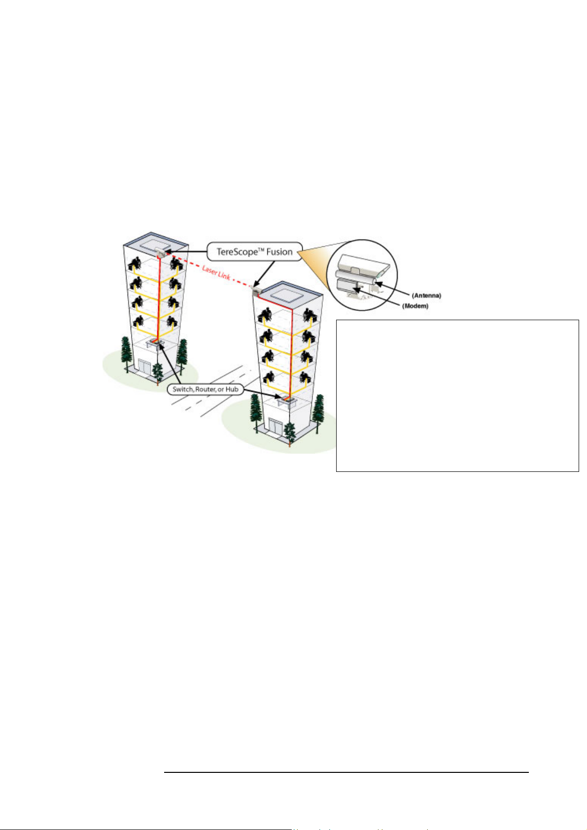
Fusion
Maximizing Link Availability in All Weather Conditions.
The TereScope Fusion was designed to combine the best features of two
transport mediums, laser light and radio waves, to form a single, seamless,
wireless communication link between network devices. By leveraging both
technologies, we can provide the 99.999% availability that your network
requires.
Protocol: 10Base-T (IEEE 802.1 1 b)
Frequency: 2.4 - 2.4835 GHz
ISM band (ETSI, FCC
2.4 – 2.497 GHz (Japan)
Output Power: -4 to 24 dBm
Sensitivity: -85 dBm
Operating Power: 110/220 VAC, 500/250
mA
Interface: Shielded RJ45
Specifications are subject to change at any time without
notice.
The TereScope Fusion has been specifically constructed to maximize link
availability between network nodes. These systems use the internationally
unlicensed, 2.4 GHz ISM band and are used as a backup for a number of
TereScope systems.
TereScope Fusion systems have an optical wireless link that provides Fast
Ethernet connectivity as the primary link and Ethernet RF as the backup link.
These systems operate in most weather conditions, including heavy rain, snow
and fog, to nearly 100% link availability. Ease of installation and freedom
from licensing make these systems very simple to deploy.
Figure 1.7b: TS & Fusion
16
Page 28
MRV Communications, Inc. – Installation Manual
r
pply
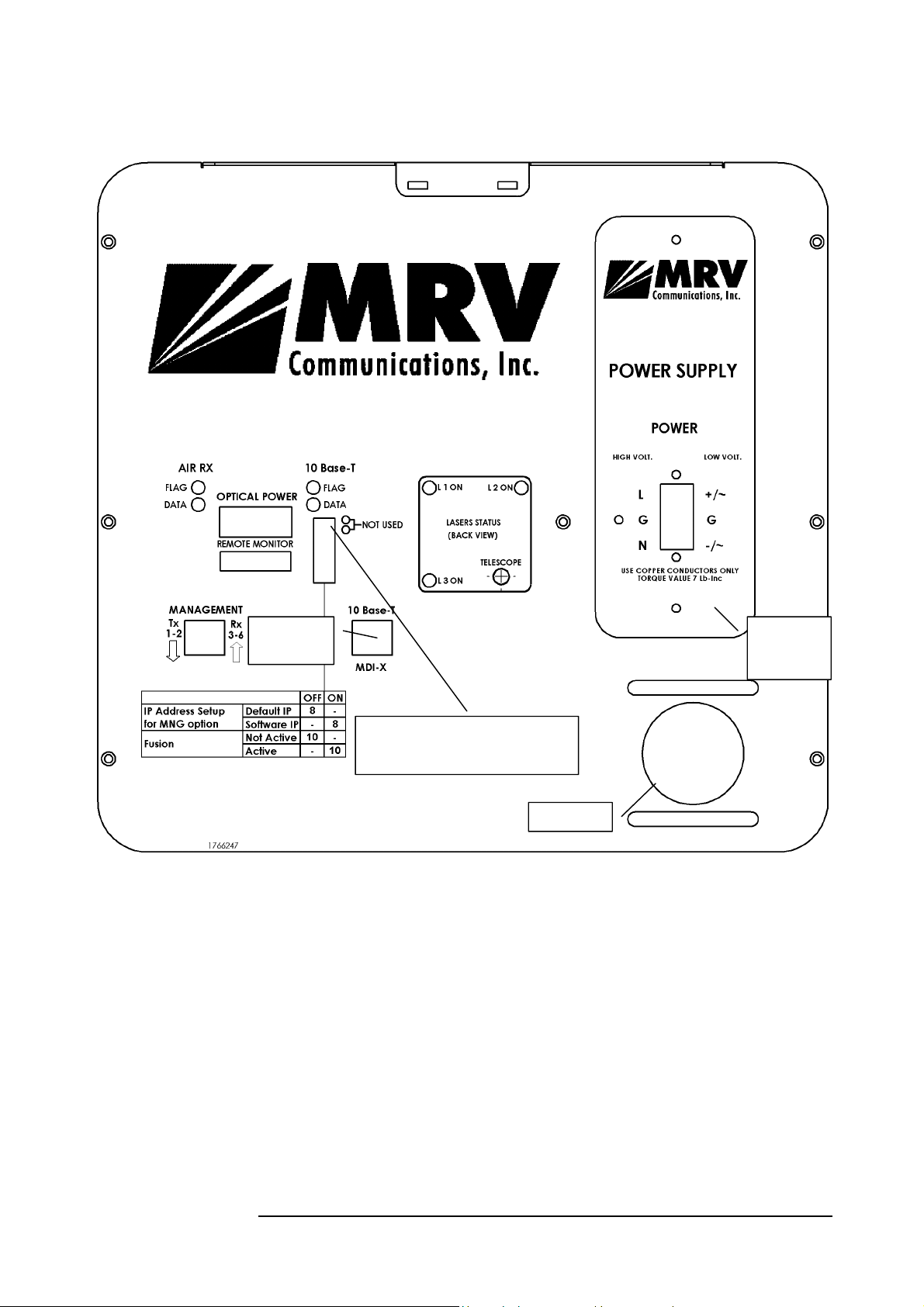
E. TS5000/ETH - Ethernet System
RJ45
Connecto
DIP Switch Toggles 1, 2, 4, 5, 6,
Figure 1.8: TS5000/ETH Model Back Panel
7, 9 positions are immaterial.
Telescope
Pluggable
Power
Su
17
Page 29
MRV Communications, Inc. – Installation Manual
Back Panel Description
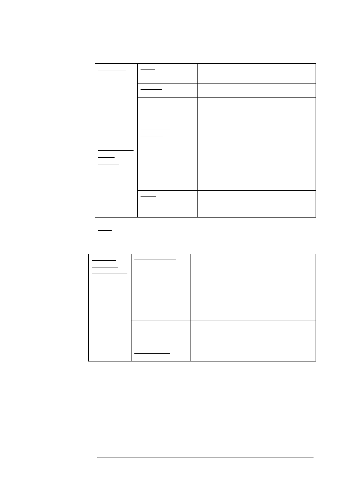
Table 4: TS5000/ETH Model Back Panel Controls, Interfaces, and Indicators
Connectors
Selectors (DIP
Switch
Toggles) --
shown on
Figure 1.8
Note:
Pins (4,5) of the main RJ45 connector can be used for dry contact purposes, for
Airlink flag alarm.
Power Power source Terminal Block (Main or UPS).
AC power supply (100 to 240 Vac) or DC power
supply (35 to 60 Vdc)
10Base-T
Remote Monitor Connection to an optional Remote Status
Management
(10baseT)
IP address set up When the Switch toggle is on OFF position, the
Fusion
This switch enables working with MRV’s Fusion
Copper interface (RJ45) for STP cables.
MDI-X connection.
Monitor or to RSM-DC (for Dry Contact
connection) (not included in the standard
transceiver kit)
Connection to 10Base-T SNMP management
interface. Pins 1,2: TX and 3,6 RX.
TereScope’s IP address is the default one (shown
on the back panel label: 10.0.0.101). To set a new
IP address, please refer to the “IP address setting
procedure for TereScope management card” file
in the Manuals CD. The new IP address is valid
only after the TereScope is powered off and on.
system. For additional info see page 8 Toggle
#10 OFF: Fusion Non Active:
Toggle #10 ON: Fusion active.
Indicators
(7-segment
display, LEDs)
Air RX Link LED Green LED indicates that a signal is received by the
Airlink receiver. Switches ON at the threshold level
Air RX Data LED Yellow LED indicates Data transfer through the
Airlink receiver
10Base-T Link LED Green LED indicates a signal is received by the
10BaseT interface. Switches ON at the threshold
level
10Base-T Data LED Yellow LED indicates Data transfer through the
10BaseT interface
Optical Power 7segment display
Digital readout indicates in mV the Optical Power
level received by the Airlink receiver
18
Page 30
MRV Communications, Inc. – Installation Manual
pply
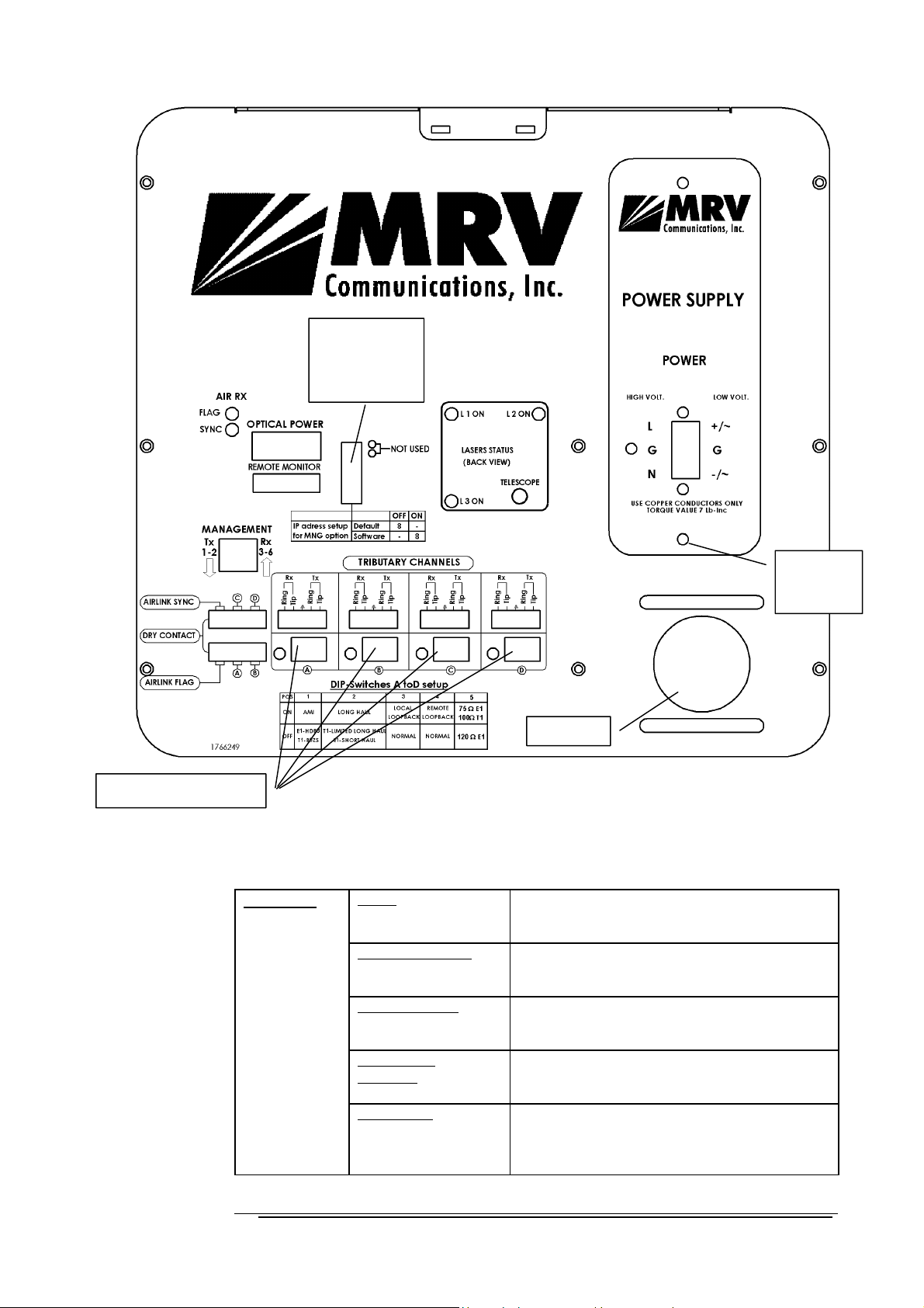
F. TS5000/4U1 - 4E1 or 4T1 System
DIP Switch
Toggles 1-7, 9,
10 positions
are immaterial.
Tributary DIP Switches
Connectors
Telescope
Figure 1.9: TS5000-4U1 Model Back Panel
Back Panel Description
Table 5: 4E1/4T1 Back Panel Controls, Interfaces, and Indicators
Power Power source Terminal Block (Main or UPS).
AC power supply (100 to 240 Vac) or DC power
supply (35 to 60 Vdc)
4 Data Connectors 4xCopper interface. Four green universal
connectors A to D to be used with coax or STP
cables.
Remote Monitor Connection to an optional Remote Status Monitor
or to RSM-DC (for Dry Contact connection) (not
included in the standard transceiver kit)
Management
(10baseT)
Dry Contact 6 dry contact outputs:
Connection to 10Base-T SNMP management
interface. Pins 1,2: TX and 3,6 RX.
1 for each interface port (total of 4)
1 for air-link flag
1 for air-link sync
Pluggable
Power
Su
19
Page 31
MRV Communications, Inc. – Installation Manual
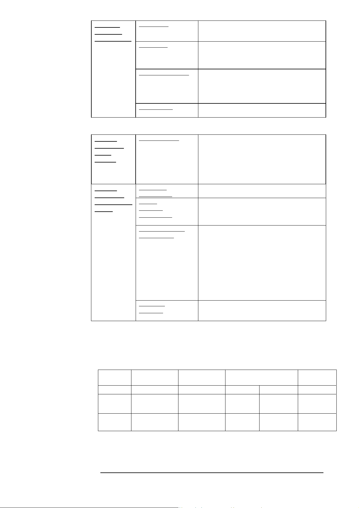
Indicators
(7-segment
display, LEDs)
Selectors
(Upper DIP
Switch
Toggles) --
shown on
Figure 1.9
Selectors
(Lower DIP
Switch Toggles
A to D) --
shown on
Figure 1.9
(All DIP switch
toggles A to D
can be set
separately.)
AirLink Flag Green LED indicates that a signal is received by the
Airlink receiver. Switches ON at the threshold
level.
Airlink Sync Yellow LED indicates that the air signal received
from the opposite side is synchronized with the
local transceiver. LED switches ON when two
transceivers are synchronized.
Tributary Link LEDs 4 yellow LEDs. Every LED indicates a signal is
received by the electrical interface in its channel.
LED switches ON when an outside signal is
received.
The channels are numbered from A to D.
Optical Power
IP address set up When the Switch toggle is on OFF position, the
Line coding
(Toggle No 1)
Receive
Sensitivity
(Toggle No 2)
Mode of Operation
(Toggles 3& 4)
Impedance
(Toggle 5)
Digital readout indicates in mV the Optical Power
level received by the Airlink receiver
TereScope’s IP address is the default one (shown
on the back panel label: 10.0.0.101). To set a new
IP address, please refer to the “IP address setting
procedure for TereScope management card” file in
the Manuals CD. The new IP address is valid only
after the TereScope is powered off and on.
Use to select the Coding mode:
AMI or HDB3 for E1 or B8ZS for T1.
Use to select Long Haul or Short Haul. Depends
on the length of the used cable: For the length of
less than 200 m, select Short Haul, for the length
over 200m, select Long Haul.
Sets the Operating mode:
LOCAL LOOP = Loops the electrical RX to the
electrical TX and Optical RX to the optical TX
REMOTE LOOP =Loops the electrical RX to
the electrical TX and optical RX to the optical TX
of the remote unit.
NORMAL = Signal received through the electrical
RX is transmitted through the Airlink TX to
opposite RX. Signal received through Airlink RX is
transmitted through the electrical TX (Normal =
3& 4 OFF).
Used to match the cable impedance.
For E1 75R or T1 100R – ON position
For E1 120R – OFF position
Dip switch setting
Every DIP switch is set up for the channel above it.
Table 6: Lower Dip Switches Setting
Switch
Position
1 2 3 4 5
ON AMI Long Haul
OFF
Line coding Receive
Sensitivity
E1: HDB3
T1: B8ZS
T1: Limited LH
E1: Short Haul
20
Operation Mode Impedance
Local
Loopback
Normal Normal
Remote
Loopback
E1: 75 Ω
T1: 100 Ω
E1: 120 Ω
Page 32
MRV Communications, Inc. – Installation Manual
a
Loop
In this state, the device performs a loop on the twisted pair through the Line
Interface, as well as another loop from AIR RX to AIR TX.
Local Loop back
The device on the side of the technician is in LOOP state when dipswitch “1”
is “ON” and Dipswitch “2” is “OFF” (for 4 E1: Dipswitch 3 ON & 4 OFF).
Remote Loop
The device on the opposite side turns to loop state by being controlled from
the near device (Master) – dipswitch “2” in “ON” and dipswitch “1” is “OFF”
(for 4E1: Dipswitch 4 ON and Dipswitch 3 OFF).
In the opposite device (Slave), both dipswitches – 1 and 2 – should be “OFF”
(Normal)(for 4E1 Dipswitches 3&4 OFF).
When turning off the Master, the Slave exits Loop state.
When the Slave does not receive an optical signal for the duration of 0.8
seconds, it exits Loop state. In this situation, when electronic Reset was not
performed on Master, the technician should shut off the device and reactivate
it.
Loop and Remote Loop Operation Mode
Heating
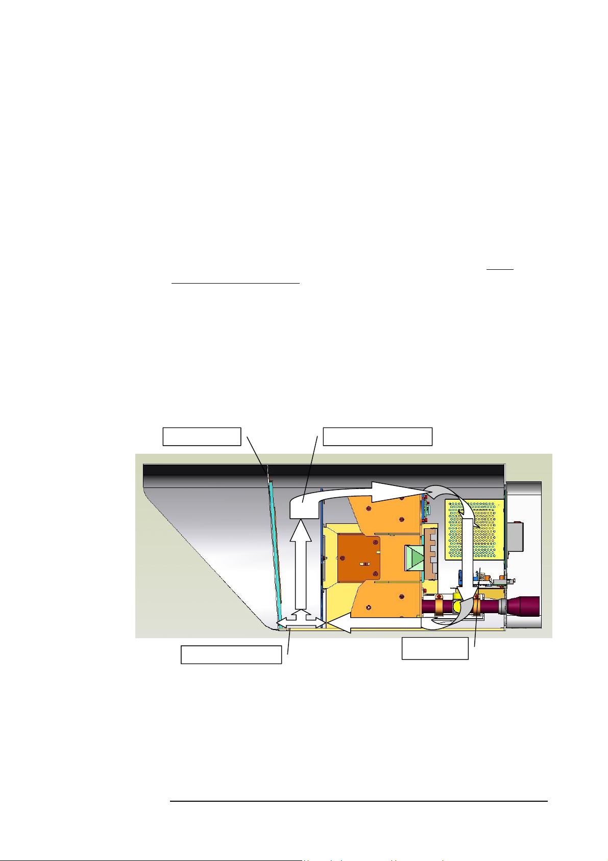
All our TereScope systems are designed with our special internal air circulation
feature, based on dissipation of the power supply heat. This prevents the
formation of condensation on the lenses under all weather conditions without
the need for additional heating at low temperatures
Front window
Holes for ventilation
Figure 1.10: Illustration of the air circulation in the TS4000 and TS5000 products
Example for air circuit.
Heating are
In spite of the aforesaid, an optional front window with the heating system
can be ordered separately (p/n TSX000-HEAT for a link). We recommend
this solution only for extremely adverse weather conditions such as heavy
snow with strong wind or high humidity.
The dissipated heat of about 25W creates a differential of about 10o between
the glass and the environment. The Heating is controlled by a Switching and
control circuit
21
Page 33
MRV Communications, Inc. – Installation Manual
T
T
RJ45
Connection for
SMNP
Interface
Monitoring and Management options
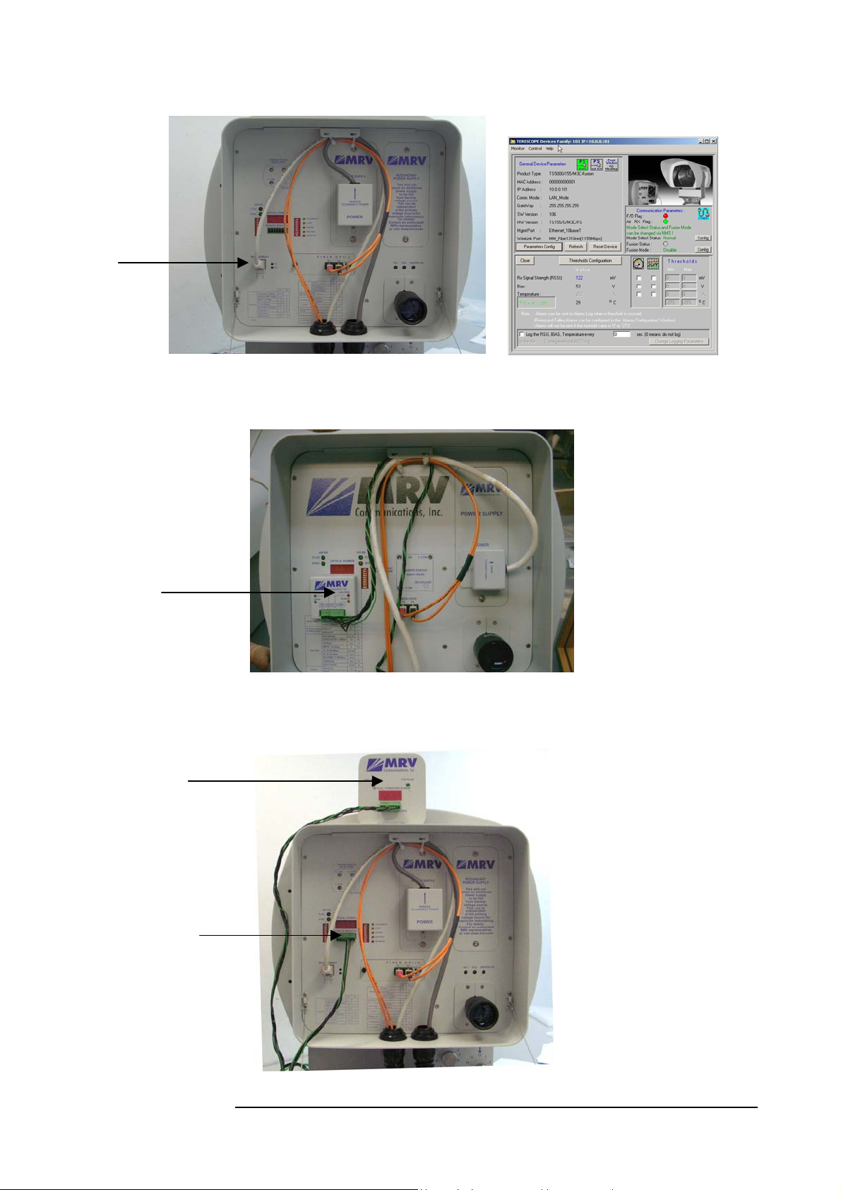
1 - Management
The TS is manageable by using
SNMP option. SNMP monitoring can
be performed via MegaVision,
MRV’s SNMP software.
Figure 1.11a: SNMP + TS. Figure 1.11b : Megavision interface
2 - Dry contact
RSM-DC
RSM connection
3 - RSM
Figure 1.12: RSM-DC +
The TS can be connected to
dry contact box (RSM-DC).
The RSM-DC is directly
attached to TS.
S
The TS can be connected to
monitoring unit: RSM. The
connection between the TS and the
RSM is made with 7 wires twisted
cable.
Figure 1.13: RSM +
S
22
Page 34
Scheme of the Connection
S
to peripheral equipment
MRV Communications, Inc. – Installation Manual
Typical Connection
1 - Fiber Connection
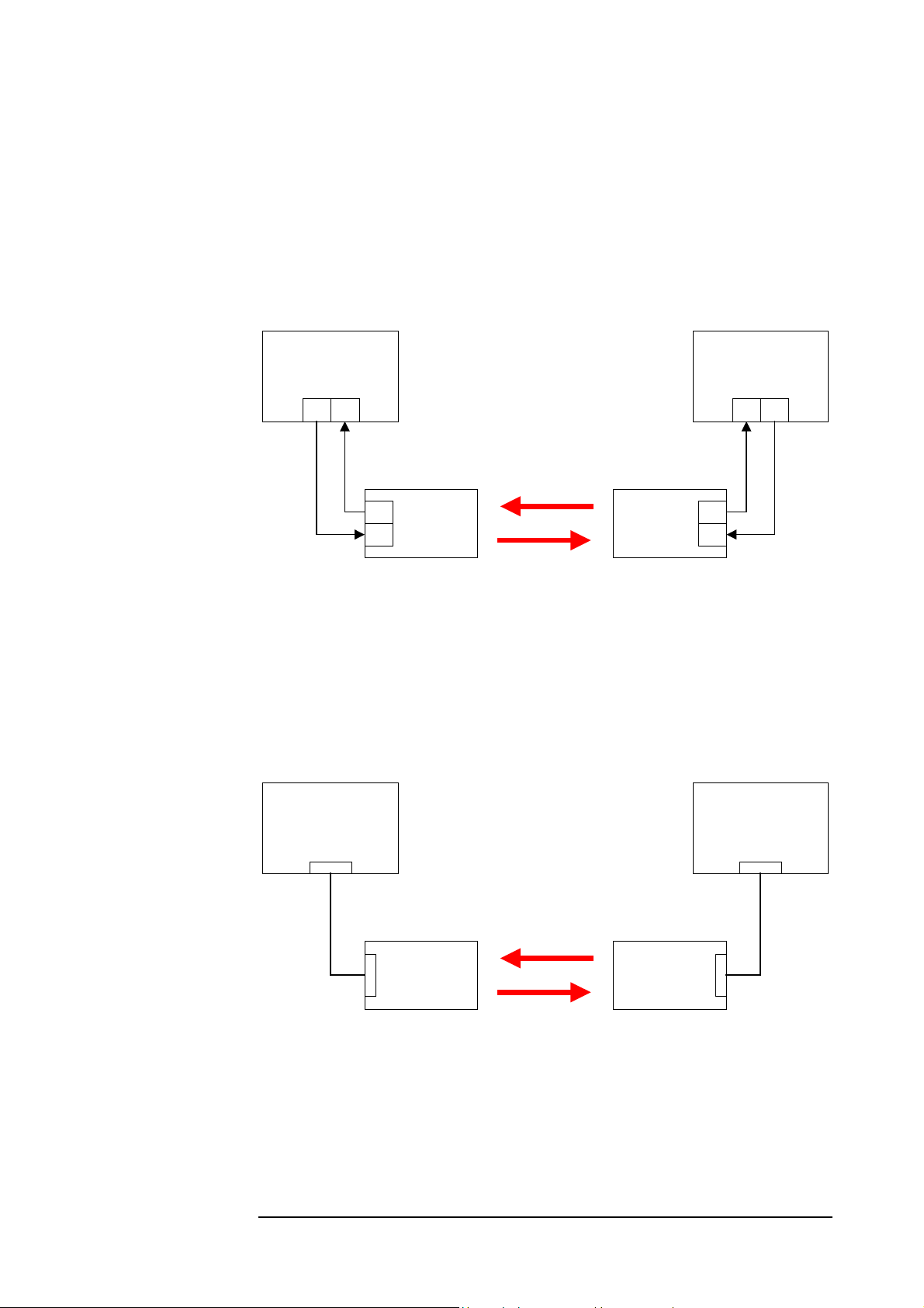
In order to implement a connection, each transceiver must be connected to the
peripheral/testing equipment through fiber optic cables. A correct connection is
notified by the display on the back panel of the transceiver (see the section Display
and Results pages 37 - 38).
IT IS A CROSS CONNECTION:
TX RX AND RX TX
Peripheral/Testing
Equipment
TX RX
Peripheral/Testing
Equipment
TXRX
Scheme of the Connection
to the peripheral
equipment
IR link
TX
RX
UWIN
TS
UWIN
Figure 1.14: Typical Connection for Models 155 and 155-F
TX
T
RX
2 - Copper Connection
In order to implement a connection, each transceiver must be connected to the
peripheral/testing equipment through a 2 pairs STP cable. A correct connection is
notified by the display on the back panel of the transceiver (see the section Display
and Results pages 37 and 38).
Peripheral/Testing
Equipment
10BaseT
STP
cable
10BaseT
TS
UWIN
IR link
TS
UWIN
Peripheral/Testing
Equipment
10BaseT
STP
cable
10BaseT
Figure 1.15: Typical Connection for Models ETH and 4U1 (4E1 or 4T1)
For 4E1/4T1 the 4 channels (or less as required) are to be connected separately.
When testing the model 4U1 (4E1 or 4T1), the matching ports on the two TS5000
heads must be connected, for e.g, if Channel A is connected on one head, Channel
A must be connected on the other head as well.
23
Page 35

MRV Communications, Inc. – Installation Manual
Chapter
Site Survey
The first step before every installation is to visit the sites to be
linked. This in order to make sure that the connection is feasible,
to find out potential obstacles or difficulties and to decide on the
location and mounting points of the transceivers
Line of Sight
An imperative condition for linking two distant buildings is that the two mounting
sites must be within a clear sight of each other.
Pay attention to:
Growing vegetation and increasing
foliage during spring
Building sites (cranes movements, ...)
Chimneys (drained away smokes could
block the beam from time to time).
Orientation
As direct sunlight could overload the airlink receiver and generate its saturation,
avoid as far as possible the East to West path link.
Note
In case this is not possible the surrounding buildings could shield the
transceiver from the direct sunlight otherwise outages lasting several
minutes (depending on the time of the year and the angle of the sun)
could occur. The system will fully recover once the sun is out of the
receiver field of view.
Location & Range
1. The mounting of the transceiver must be extremely rigid
(preventing the installation from twists of 1 mrad). The key to
the required rigidity is to attach the mounting accessories on
strong mounting points such as:
- Stiff building structures
- Concrete or reinforced concrete surfaces
24
Page 36
T
r
(1)
l
In case such situations
could not be bypassed, specia
mounting accessories and
techniques must be designed
and considered (see section
Particular Figure
Cases\Techniques page 45)
MRV Communications, Inc. – Installation Manual
Prefer Avoid Pay attention to
Concrete Parapet
Structural wall or
column
For reasons of convenience, it is always preferable to install the
units indoors as long as all the required conditions previously
described are satisfied and the customer/building owner allows
it. However, when windows are present in the beam path, the
attenuating factor of the glass must be considered regarding the
distance and the required fade margin.
2. Referring to the data in Appendix A: Product Specifications, set and
record the distance between the two TereScopes of the link. (You can
use any of the following equipment to determine the distance:
rangefinder laser binoculars, GPS receiver, maps...)
3. Noting that two TereScope units are required per link, record the
quantity of each model of the TereScope required.
4. Record the bearing to the opposite site by compass.
5. Record the number of links to be installed at the site.
6. Note whether additional sheltering is needed for the TereScope, for
e.g., against strong winds (120km/h or more)
CONSULT FACTORY IN CASE OF DOUBT!
Old constructions
Soft material (asphalt, etc.)
Non-uniform surfaces
Wooden and metal
structures
Colored windows
Double glazing
he proximity of powe
radio antennas
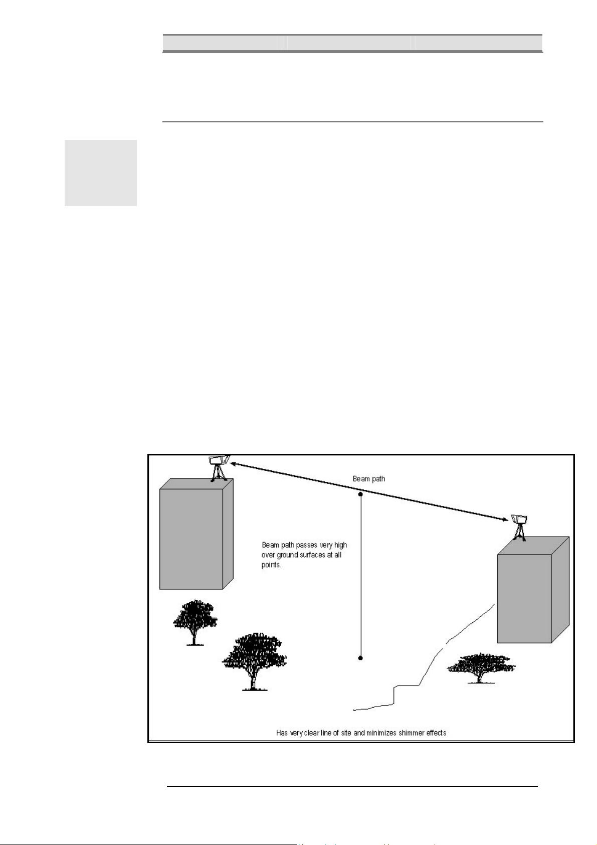
Figure 2.1 and Figure 2.2 show optimal and acceptable locations for the
TereScope links. Notice that in both figures the TereScopes are mounted on
rooftop edges and high enough above the ground.
TereScope mounted at corner of
leading edge of structure.
Figure 2.1: Optimal Mounting
25
Page 37
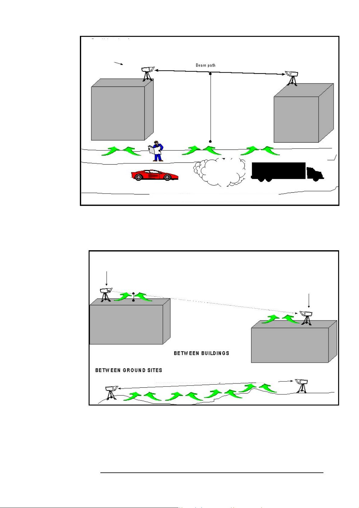
MRV Communications, Inc. – Installation Manual
TereScope at edge of roof so
that heat rising from roof
surface does not affect beam
Beam path more than
4.5 m (15 ft) above
surface to avoid traffic
and rising heat.
Figure 2.2: Acceptable Mounting
Figure 2.3 shows an unrecommended TereScope link location because of
interference by IR. Notice that the TereScopes are mounted far from the rooftop
edges or are too close to the ground.
TereScope not at edge of roof.
Less than 4.5 m (15 ft) between beam
path and heat-emitting surface.
Beam path passes too close to ground. Heat rising causes scintillation.
Allow 4.5 m (15 ft) between ground and beam path.
TereScope not at edge of roof.
Figure 2.3: Unrecommended Mounting
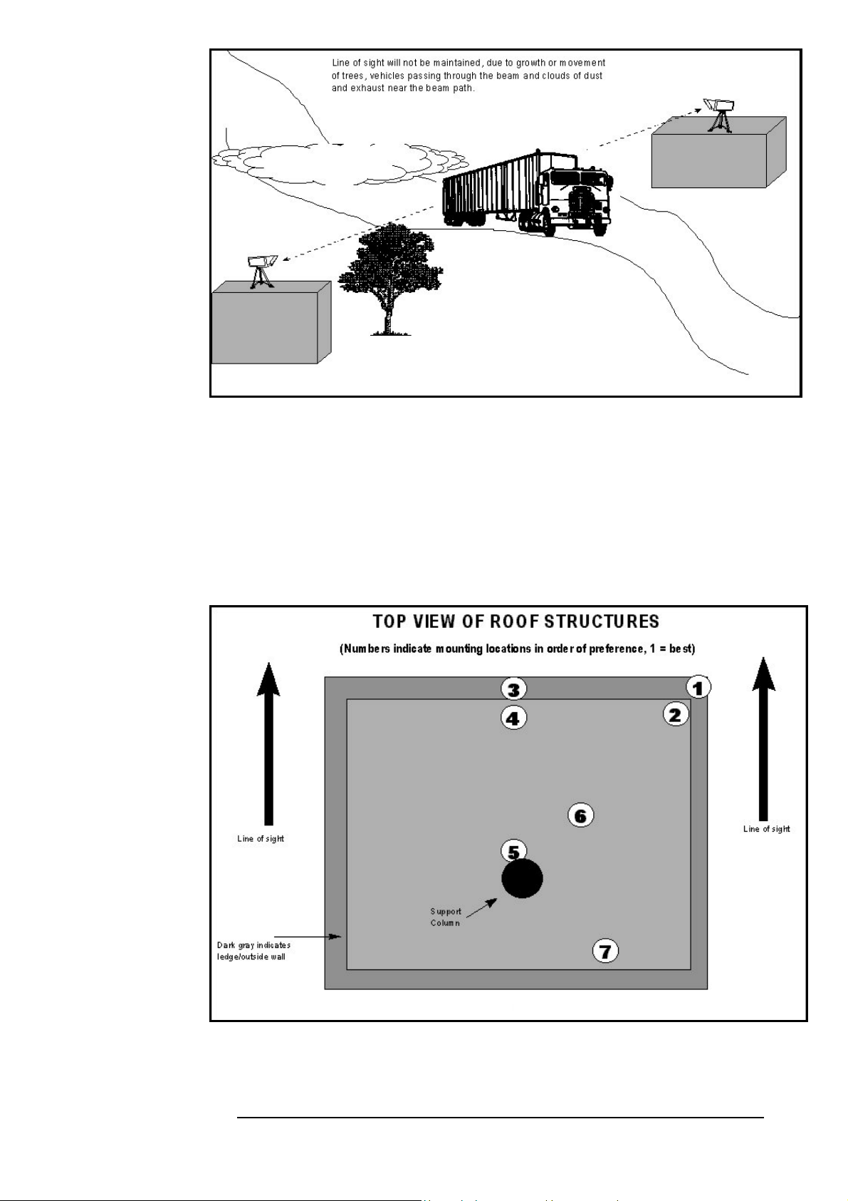
Figure 2.4 shows an unacceptable TereScope link location because of interference by
passing vehicles. Notice that the TereScopes are mounted far from the rooftop
edges and not high enough above the ground.
26
Page 38
MRV Communications, Inc. – Installation Manual
v
Figure 2.4: Unacceptable Mounting
Mounting Environment & Stability
1. When deciding the mounting location, you should look on the rooftop
for vibration sources such as compressors, elevators, motors, and try to avoid
them.
2. Photograph the mounting location so as to select the best mounting
option.
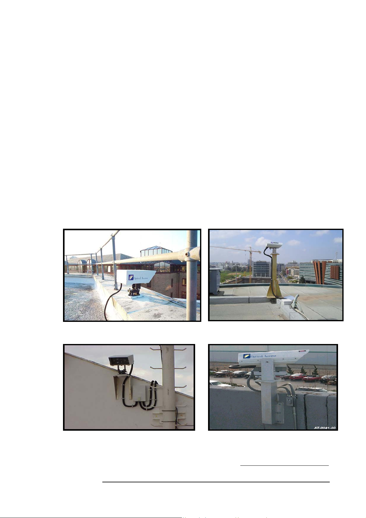
Figure 2.5 shows mounting locations on a rooftop in descending order of
preference. Location 1 is the best; location 7 is the worst.
Figure 2.5: Mounting Locations in Order of Preference
Note:
If the only option to mount the TereScope is at points 5, 6 or 7, it has to be mounted at least 2 m above the rooftop to o
the roof scintillation and eventually have people crossing the link beam (If possible, avoid placing the TereScope on the mast).
27
Page 39
MRV Communications, Inc. – Installation Manual
3. Avoid surfaces with high reflectivity (e.g., white walls) behind the
TereScope so as to reduce interference with the optical signal.
4. Get customer approval for the exact positions where the TereScopes will
be mounted. Using paint, mark these positions.
5. Note the height that each TereScope will be above or aside the rooftop.
6. Identify the floor or wall type and dimensions of the location at which
the TereScope is planned to be mounted.
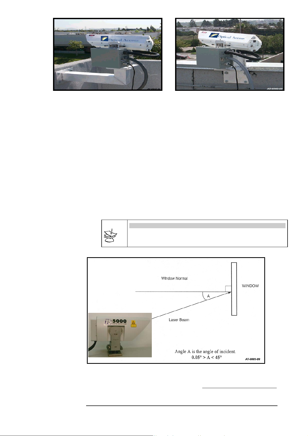
7. For each TereScope unit, select one of the following mounting options2
and record it.
a. Parapet/Ledge Mounting (Figure 2.6) – This is a standard
mounting option that uses only the Plate (JMP).
b. Wall Mounting (Fig. 2.8) – This is a standard mounting option
that uses the Plate (JMP) as well as the two Brackets (JMB).
c. Floor Pedestal Mounting (Figure 2.7) – This is a non-standard
mounting option that uses the Plate (JMP) as well as a Floor Pedestal (e.g.,
M015C).
d. Wall Pedestal Mounting (Figure 2.9) – This is a non-standard
mounting option that uses the Plate (JMP) as well as a Wall Pedestal (e.g.,
M054C).
e. Extended Wall Mounting (Figure 2.10) – This is a non-
standard mounting option that uses the Plate (JMP) as well as an Extended
Wall (e.g., M062C).
f. Angle Bracket Mounting (Figure 2.11) – This is a non-
standard mounting option that uses the Plate (JMP) as well as an
Angle Bracket (e.g., M001).
Figure 2.6: Parapet/Ledge Mounting (using JMP only)
Figure 2.8: Wall Mounting (using JMP and JMB)
2
For more information on these mounting options, refer to TereScope Installation Guide (Publication No.
46366).
Figure 2.7: Floor Pedestal Mounting (using JMP and
MO15C)
Figure 2.9: Wall Pedestal Mounting (using JMP and
MO54C)
28
Page 40
MRV Communications, Inc. – Installation Manual
Figure 2.10: Extended Wall Mounting (using JMP and
MO62C)
Transmitting through a Window
1. Determine the number of surfaces the beam transits or is reflected
from, the reflectivity of each surface, and
condensation/precipitation collection areas.
2. Use the data below to determine whether the light beam
attenuation is acceptable.
4% attenuation for each surface of light reflection.
15% attenuation for a double pane window.
Attenuation due to tint in windowpane must be taken into
consideration in choosing the right TereScope model. (The %
attenuation depends on the tint and must be measured.)
3. Ensure that the angle of incidence3 of the beam striking the
windowpane is between 1º and 45º.
Note
On high buildings, for indoor window installation, the user should consider
that occasionally the window-cleaning elevator might block the link beam.
Figure 2.12 shows the arrangement for transmitting through a window
Figure 2.11: Angle Bracket Mounting (using JMP and
M001)
Figure 2.12: Arrangement for transmitting through a window.
2
Angle which the light beam makes with the perpendicular to the windowpane
29
Page 41
MRV Communications, Inc. – Installation Manual
Chapter
Infrastructure
The only infrastructure required for operating the transceiver and
linking the sites is Power and Data/Signal connection to the
peripheral networking equipment. This must be ready prior to the
airlink installation
IN OUTDOOR INSTALLATIONS, USE SHIELDED AND
WEATHERPROOF MATERIALS (CABLES, INLETS, AND
CONNECTORS) COMPLIANT TO THE SAFETY STANDARD IN
FORCE.
Power
Source
.
The power requirement for standard units is 100-240VAC @
50/60Hz - 22W.
Note: Units requiring low Voltage: 35-60VDC - 22W can be factory
set upon request.
It is recommended to use Surge Suppression System to avoid
the damage to the equipment when power supply is unstable.
Protection should be at least 25,000A min.
Cabling
Standard 3 conductors power cord are required. (See Safety
requirements, Page iv)
Data/Signal Cabling
1. For TS5000/G, TS5000/G-F, TS5000/155 and TS5000/155-F
Type
For connecting the Transceiver to the peripheral equipment two optical
fiber cables are required (one for the transmission and one for the
reception). The standard recommended cable is a 62.5/125 μm for MM
fiber and 9/125 μm SM fiber, according to transceiver type used.
Connectors
Each fiber should be terminated with the ordered type of connector on the
transceiver end (SC, ST….).
Optical Fiber testing.
The cabling installer must specify the attenuation of each fiber installed.
30
Page 42
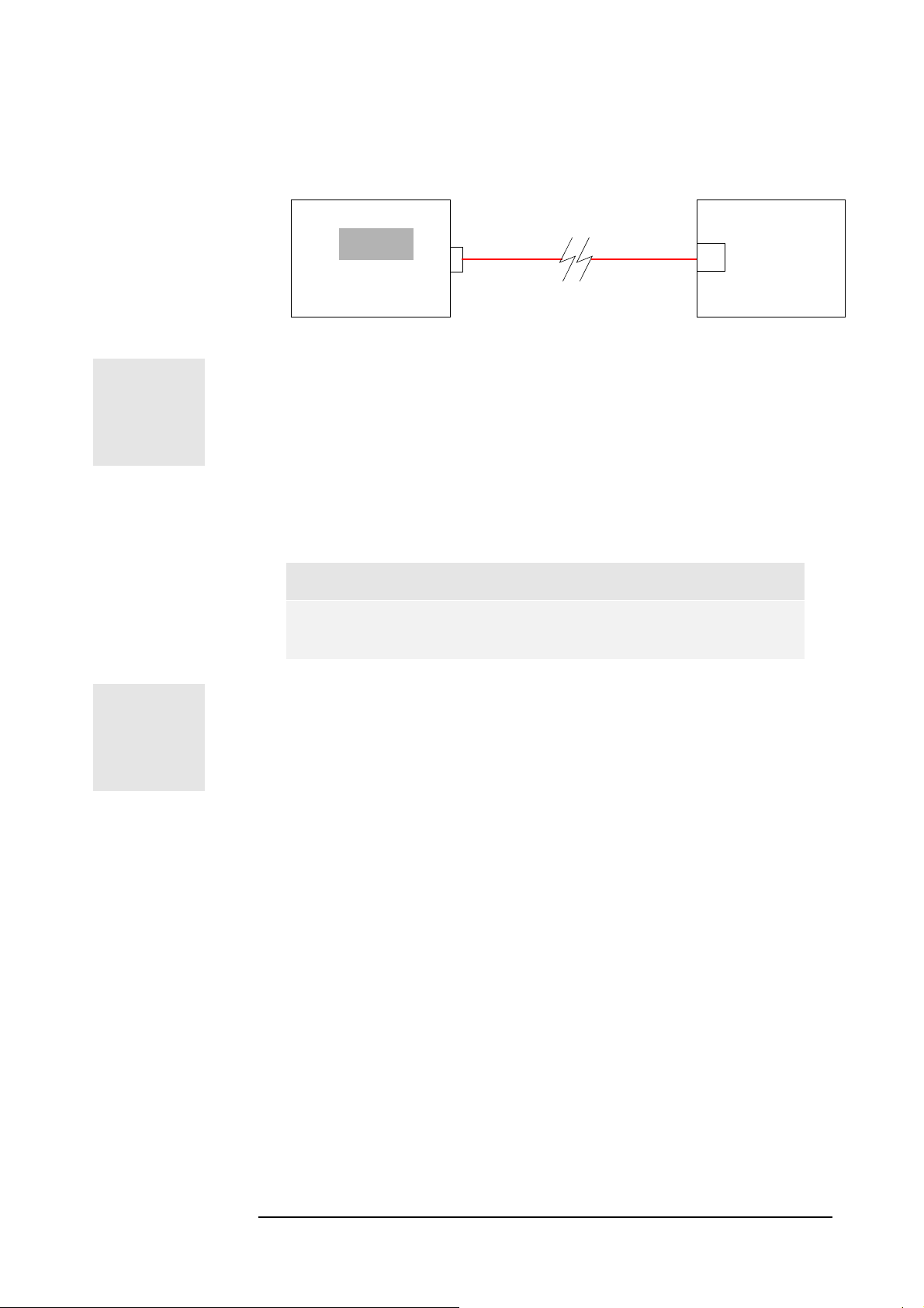
MRV Communications, Inc. – Installation Manual
A simple power loss test can inform us about the condition of the fibers.
This test consists of measuring with an optical power meter the output
power at one end of the tested fiber as at the other end a fiber source is
connected. If the values are in dBm, the difference between the input
power and the output power gives the power attenuation of the fiber (in
dB).
Fiber Optic
Cable
dBm
Optical Power Meter
Figure 3.1: F/O cable test.
In case the above equipment is not available, a simple visual test may be
performed to locate and reject badly damaged fibers. Place near one end of
the fiber a light source and block alternatively the termination, you must
observe the light coming out of the other end. (This procedure does not
guarantee that a fiber is acceptable)
A standard 62.5μm fiber optic cable is characterised by an
attenuation factor of around 3 to 5dB/km. Then a loss value of more
than 3dB for runs up to 200m can indicate a suspect fiber.
Note
The fiber optic cables must be installed by a specialist.
Peripheral
F/O
Equipment
TX
Optical Source
or
HANDLE THE FIBERS VERY CAREFULLY.
2. For TS5000/ETH
Type
For connecting the Transceiver to the peripheral equipment a 2 pairs STP
cable is required (one pair for the transmission and one for the reception).
This cable must be a straight one when the peripheral has an MDI-X 10
Base T interface and a Gross one otherwise.
Connectors
The cable should be terminated with an RJ-45 connector on the
Transceiver end.
3. For TS5000/4U1 (4E1 or 4T1)
Type: For connecting the Transceiver to the peripheral equipment a 2
pairs STP cable is required (one pair for the transmission and the other for
the reception) for each E1 or T1 connection.
Connectors A special connector is provided by MRV to connect the
twisted pair cables to the TS.
31
Page 43

MRV Communications, Inc. – Installation Manual
Bench T est
It is always easier and more convenient to locate a failure and
solve a problem in a lab on a bench than on a roof under bad
conditions. It is then strongly recommended, as the
circumstances allow it, to perform a bench test with all the
modules prior to the installation in order to check the equipment
compatibility and to validate the configuration.
Chapter
See Unpacking Instructions in Appendix C.
1 - TS5000/G & TS5000/G-F
Compatibility
Peripheral equipment
Check the operating of the peripheral equipment connecting them through cables
(see Configuration 1 below).
Interfaces
Check the specifications compatibility (type, wavelength, receiver range, output
power, data rate) between the TereScope and the peripheral equipment interfaces.
Testing equipment
Chose an appropriate BER (Bit Error Rate) tester for checking the physical link
quality. A portable one is preferred for convenient use in the field.
For example: A smartbit Giga Ethernet tester.
A ping test or a file transfer between two workstations - connected to the
networking equipment - is useful and easy to implement for testing the
performance of the whole configuration.
Setup
Dip-switch
Set all the DIP switch toggles to the OFF position for normal operation.
32
Page 44

MRV Communications, Inc. – Installation Manual
2 - TS5000/155 & TS5000/155-F
Compatibility
Peripheral equipment
Check the operating of the peripheral equipment connecting them through cables
(see Configuration 1 below).
Interfaces
Check the specifications compatibility (type, wavelength, receiver range, output
power, data rate) between the TereScope and the peripheral equipment interfaces.
Testing equipment
Chose an appropriate BER (Bit Error Rate) tester for checking the physical link
quality. A portable one is preferred for convenient use in the field.
For example: the OC3port plus SONET and ATM analyser manufactured by
Fluke.
A ping test or a file transfer between two workstations - connected to the
networking equipment - is useful and easy to implement for testing the
performance of the whole configuration.
Setup
Data Rate DIP Switch Toggle
According to the application in use, set the switch DS1 toggles as indicated in the
following table:
Table 7: DIP Switch Setting for TereScope
Function
Fast Ethernet
ATM/OC3/STM1: 155 Mbps
SMPTE 143 Mbps
E3:34.368 Mbps 1,2,4 3
T3:44.736 2,4 1,3
OC1/STMO:51.840 Mbps 1,4 2,3
Cus t o mize d 1 4 1,2,3
Cus t o mize d 2 1,3,4 2
Ope n P r o t ocol 1,2,3 4
Mode Select DIP switch toggle
Set DIP switch toggles 1, 2 and 4 to the OFF position for normal operation.
TS5000/155
OFF ON
1,2,3,4 –
2,3,4
3,4
1
1,2
3 - TS5000/ETH
Compatibility
Peripheral equipment
Check the operating of the peripheral equipment connecting them through cables
(see Configuration 1 below).
33
Page 45

MRV Communications, Inc. – Installation Manual
Interfaces
Check the specifications compatibility (type, data rate) between the TereScope and
the peripheral equipment interfaces.
Testing equipment
Chose an appropriate BER (Bit Error Rate) tester for checking the physical link
quality. A portable one is preferred for convenient use in the field.
A ping test or a file transfer between two workstations - connected to the
networking equipment - is useful and easy to implement for testing the
performance of the whole configuration.
Setup
Dip-switch
Set all the DIP switch toggles (other than 8 and 10 which are for SNMP
management and Fusion) to the OFF position for normal operation.
4 - TS5000/4U1
Compatibility
Peripheral equipment
Check the operating of the peripheral equipment connecting them through cables
(see Configuration 1 below).
Interfaces
Check the specifications compatibility (type, standard compliance) between the link
and the peripheral equipment interfaces.
Testing equipment
Chose an appropriate BER (Bit Error Rate) tester for checking the physical link
quality. A portable one is preferred for convenient use in the field.
Dip-switch Setup
• Main Dip-Switch: Set all the DIP switch toggles (other than 8 and 10
which are for SNMP management and Fusion) to the OFF position
for normal operation.
• Dip switch under the port in use: - switches 3&4 OFF for normal
operation.
- Line coding (AMI or HDB3) – Toggle 1.
- Receive Sensitivity (Short/Long Haul) – Toggle 2.
- Impedance (75 ohm/120 ohm) – Toggle 5.
34
Page 46
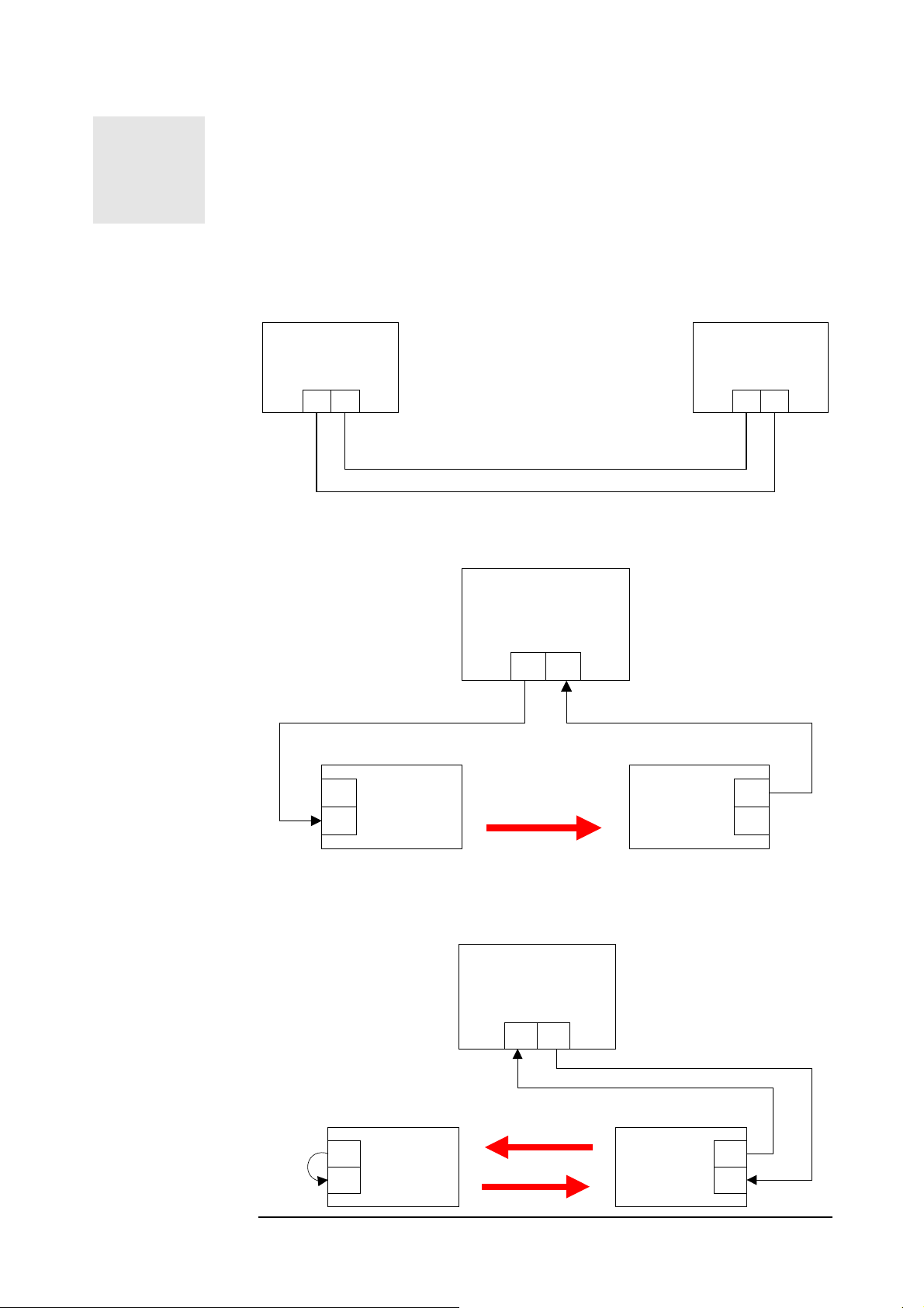
MRV Communications, Inc. – Installation Manual
Test Configurations
IN ALL THE FOLLOWING CONFIGURATIONS TAKE CARE TO ADJUST
THE TRANSCEIVERS OUT OF SATURATION, ALIGNING THEM
SLIGHTLY IN AN ANGLE SO THAT THE DIGITAL READOUT SHOWS A
READING LOWER THAN 1200 BUT HIGHER THAN 100.
Peripheral equipment
and cable testing
One way Airlink
BER test
Bench test
To learn more about TS Bench Test please refer to Appendix E.
Configuration 1: (Applicable without TereScope)
Peripheral/Testing
Equipment
RX TX
Cables
Configuration 2: (Applicable to all models)
BER Tester
Peripheral/Testing
Equipment
TXRX
Loop-back Airlink
BER test
TX
UWIN
RX
Configuration 3: (Applicable to all models)
TS
TX RX
IR link
BER Tester
TXRX
UWIN
TS
TX
RX
TX
RX
UWIN
TS
IR link
35
UWIN
TS
TX
RX
Page 47
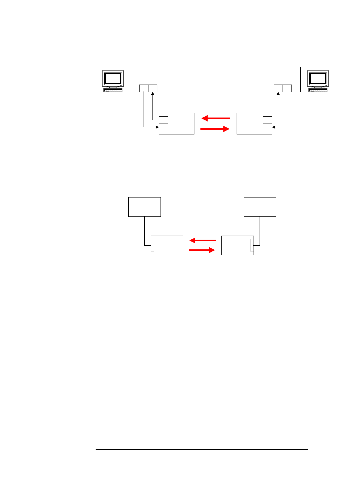
Whole configuration
operating test (Ping test
or File transfer) for
Ethernet or Fast
Ethernet systems
Whole configuration
operating test for all
models
MRV Communications, Inc. – Installation Manual
Configuration 4: (Applicable to models G, G-F, 155, 155-F, and ETH)
Peripheral
Equipment
TX RX
IR link
TX
UWIN
TS TS
RX
UWIN
Configuration 5: (Applicable to all models)
Peripheral/
Testing
Equipment
Peripheral/
Testing
Equipment
Peripheral
Equipment
TXRX
WorkstationWorkstation
TX
RX
STP
cable
TereScope
IR link
TereScope
STP
cable
36
Page 48
Indicator →
T
T
Position ↓
ON
OFF
MRV Communications, Inc. – Installation Manual
Display and Results
1. TS5000/G & TS5000/G-F
Proper Display
1. Indicators
AIR RX F/O RX1 Management2 Align. Loop Fusion3 Heating4 SW
Mode
Flag Sync TX RX TX RX
x X
x x x x x x x x x
Notes
1 - In case the tested TereScope has a Fusion option, the LEDs of the redundant F/O should be
switched off if the backup is inactive.
2 – TX LED Flashing when the RSM-SNMP is connected and the TereScope is transmitting
management Data. (There is no Link indication)
RX LED Flashing when the RSM-SNMP is connected and the TereScope is receiving management
Data. (There is no Link indication)
able 8: Indicators
Lasers Status
5
L1 to L36
x
3 - This LED switches ON, when the fusion option is enabled. It starts blinking, when fusion is
active, i.e. when the IR link stops operating and the back-up link becomes active.
4 - This LED switches ON only when there is a heating option. The heating is activated by moving
the DIP Switch toggle # 5 to ON position.
5 - When the RSM-SNMP is connected and you choose to control the TereScope by software
(Megavision), move the DIP Switch #10 to ON position and this LED will switch ON.
6 - L1 is OFF if Dip switch toggle #3 is on ON position
2. Received power
100 < OPTICAL POWER < 1000
Expected Results
The BER must be less than 10E-12 (10
short tests.
The PING test and file transfer procedure should not notify any TIME OUT alarm
or last too long time compared to cabling connection.
-12
) for on-going tests and error-free for
2.
TS5000/155 & TS5000/155-F
Proper Display
1. Indicators
Indicator →
Position ↓
ON
OFF
AIR RX F/O RX1 Management2 Align. Loop Fusion3 Heating4 SW
Mode
Flag Sync Flag Sync TX RX
x x
x
x
x x x x x x x
able 9: Indicators
37
Lasers Status
5
L1 to L3
x
Page 49
MRV Communications, Inc. – Installation Manual
T
Notes
1 - In case the tested TereScope has a Fusion option, the LEDs of the redundant F/O should be
switched off if the backup is not connected.
2 – TX LED Flashing when the RSM-SNMP is connected and the TereScope is transmitting
management Data. (There is no Link indication)
RX LED Flashing when the RSM-SNMP is connected and the TereScope is receiving management
Data. (There is no Link indication)
3 - This LED switches ON, when the fusion option is enabled. It starts blinking, when fusion is
active, i.e. when the IR link stops operating and the back-up link becomes active.
4 - This LED switches ON only when there is a heating option. The heating is activated by moving
the DIP Switch toggle # 5 to ON position.
5 - When the RSM-SNMP is connected and you choose to control the TereScope by software
(Megavision), move the DIP Switch #10 to ON position and this LED will switch ON.
2. Received power
100 < OPTICAL POWER < 1000
Expected Results
The BER must be less than 10E-12 (10
short tests.
-12
) for on-going tests and error-free for
The PING test and file transfer procedure should not notify any TIME OUT alarm
or last too long time compared to cabling connection.
3. TS5000/ETH
Proper Display
1. Indicators
Indicator →
Position ↓ Link
ON
OFF
Blinking
AIR RX 10 Base-T
Data
x x x
Link Data
x
able 10: Indicators
2. Received power
100 < OPTICAL POWER < 1000
Lasers Status
L1 to L3
x
Expected Results
The BER must be less than 1E-9 for lasting tests and display NO ERRORS for
brief ones.
The PING test and file transfer procedure should not notify any TIME OUT alarm
or last too long time compared to cabling connection.
38
Page 50

MRV Communications, Inc. – Installation Manual
T
4. TS5000/4U1 (4E1 or 4T1)
Proper Display
1. Indicators
Indicator →
Position ↓
ON
OFF
AIR RX
Link
Sync
x x
Tributary
Channels
A to D
x
(for the connected
port)
x
(for the not
connected port)
able 11: Indicators
2. Received power
100 < OPTICAL POWER < 1000
Lasers Status
L1 to L3
x
Expected Results
The BER must be less than 1E-9 for lasting tests and display NO ERRORS for
brief ones.
Note: When placing the two TS5000 face to face you need to do:
1. Cover with a tape two of the three transmitters, leaving only one
transmitter free. Recommended distance for bench test is between
1.5 to 2m’ apart.
2. Before doing the BER test you have to verify that there are no
“reflections” from the front window: Shut down the power from
unit A and make sure that the RSSI value on unit B drops to “000”
or to the levels that the “Air RX” LED is OFF. Do the same
shutting down unit B. if you have RSSI reading when shutting
down one of the units, you need to fine align it until you get RSSI
value of “000” or the “Air RX” LED to OFF position.
3. Only when part 1 & 2 are done you can start the BER test of file
transfer test.
SNMP Management Setting and Operation
General: Given the small amount of information and parameters that the SNMP agent
module of the FSO product line deals with, the card has a moderate memory size and CPU
type. If the management Ethernet port is connected to a network with higher rate of broadcast
and multicast traffic, slow SNMP management response of the FSO may occur.
Recommendation:
The recommended solution for this symptom is to isolate the Switch port connecting the FSO
SNMP management module to the network from the network traffic by assigning it to a
dedicated VLAN usually used for network management. If possible also limit the ingress
broadcast rate to that specific port.
To set a new IP address, please refer to the “IP address setting procedure for TereScope
management card” file in the Manuals CD
39
Page 51
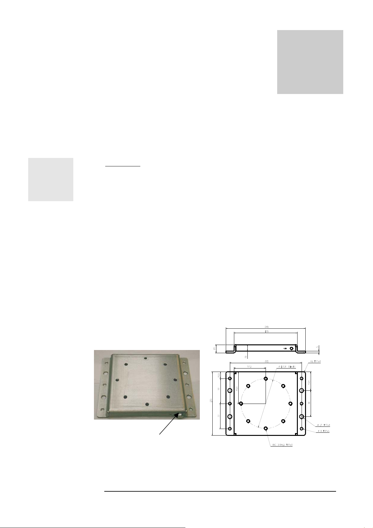
A
g
g
MRV Communications, Inc. – Installation Manual
Chapter
Installation
This chapter deals with the mounting of the hardware and the
unit on the site (see Appendix D for the required material).
See Unpacking Instructions in Appendix C.
CAUTION: Unit to be mounted in horizontal position only. Max angle 45o
Accessories
The standard mounting accessories are supplied with the transceiver in a kit. They
are designed for typical mounting on horizontal and vertical surfaces.
JMP-8
Mounting Plate
(dimensions in mm)
Description
The accessories kit (supplied by MRV) consists of :
o The Mounting Plate (JMP-8)
o The Alignment Device (AD-5000)
o The Installer Tool Kit (JITK-8)
The JMP-8 is used for mounting the transceiver on the support surface. (i.e. to a
horizontal concrete surface/plate only) the JMP-8 is not fit to the MRV standard
mounting brackets, if needed to mount it on MRV standard mounting brackets,
attach the AD5000 base plate directly to the mounting bracket top plate without
the JMP-8
The AD-5000 allows the aiming of the two units making the link (see chapter 6)
: Screw for
roundin
Figure 5.1a: JMP-8
Dimensions in mm
Figure 5.1b: JMP-8
40
Page 52
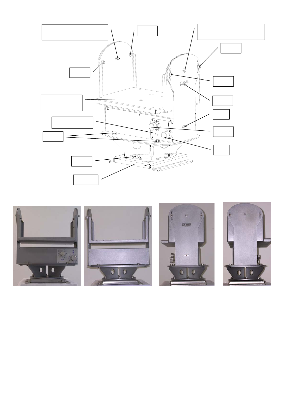
CAUTION!
Do not touch this screw (K)
AD-5000
Alignment Device
for TS5000 systems
Enforced Base
Plate
Alignment Scale
MRV Communications, Inc. – Installation Manual
J-L-3
J-L-2
CAUTION!
Do not touch this screw (K)
J-R-3
J-R-2
L
M
E
D
JMP-8
B
C
Fig. 5.2: Alignment device (AD-5000) + JMP-8
Fig. 5.3: Back Fig. 5.4: Front Fig. 5.5: Right Fig. 5.6: Left
B Right-Left fine alignment knob
C Up-Down fine alignment knob
D Locking screws between AD-5000 & JMP-8
E Horizontal aiming locking screws
J-R Vertical Aiming locking screws (Right side)
J-L Vertical Aiming locking screws (Left side)
K Vertical aiming axis
L Coarse alignment screw
M Red reference point
41
Page 53
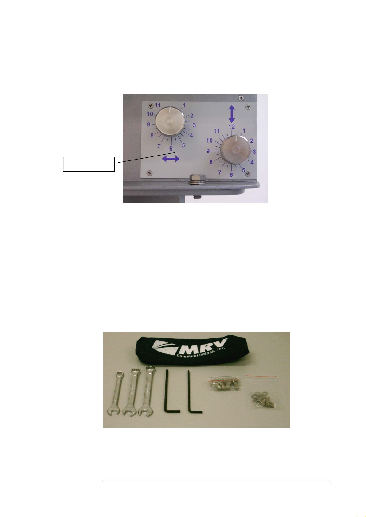
Alignment Scale
JITK: Installer Tool
Kit
MRV Communications, Inc. – Installation Manual
Alignment Knobs
The Fine Alignment mechanism of the TS5000 is fragile and must therefore be
handled gently. On the AD-5000 and under the alignment knobs are scales
that aid the installer in easily and quickly performing optimal alignment. Each
full turn of a knob rotates the head of the TS5000 by an angle of 2.15 mrad.
Accordingly, a turn equal to a turn from one number to the next rotates the
head by 0.18 mrad, and a turn equal to a turn from marking to the next rotates
the head by 0.09 mrad.
Fig. 5.7: View on Alignment Knobs
The Installer Tool Kit (JITK-8)
The JITK-8 tool kit includes the work tools required for opening and closing
nuts and screws of the TS5000 for optimal installation. It is recommended that
these tools be used. MRV supplies this tool kit with each TS5000 head. In
addition to the tool kit, screws are supplied for mounting the JMP-8 and AD5000 on a pedestal that is supplied by MRV as an option.
Fig. 5.8: JITK: Installer Tool Kit
42
Page 54
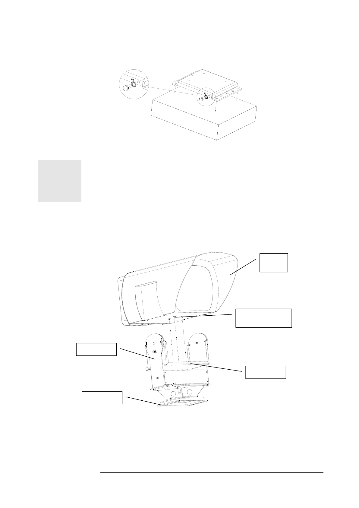
MRV Communications, Inc. – Installation Manual
b
Mounting
1- Accessories
• Horizontal surfaces (parapet, ...):
THE JMP SHOULD BE ORIENTED IN SUCH A WAY THAT THE GROUNDING
SCREW IS LOCATED ON THE BACK (CLOSE TO THE INSTALLER) AND THE
FRONT IS FACING THE OPPOSITE SITE.
Figure 5.9: JMP on the fixation surface
2- Attachment of the Transceiver (TS)
In order to place the Transceiver in the right place on the swing base, direct
and insert three screw heads from the bottom of the box to three bigger holes
on the swing base
TS5000
Head
G: Screws from the
ottom of the box
AD-5000
Swing Base
JMP-8
Fig. 5.10: Mounting TS5000 on Alignment Device
Screw 4 screws (M6x30mm x ½” length) with the spring washers to fix the
transceiver on the swing base. These 4 screws should be locked tightly with
the help of appropriate tools.
43
Page 55
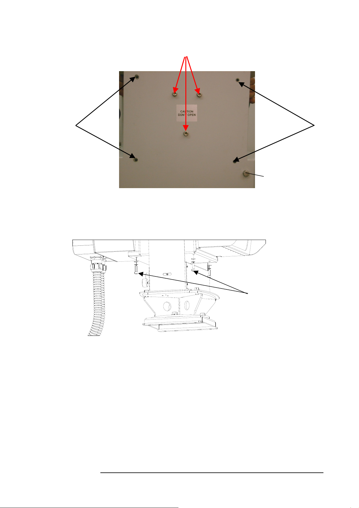
MRV Communications, Inc. – Installation Manual
CAUTION!
Do not open Screws G.
H
Fig. 5.11a: Bottom view: Locking screws (H) between TS and alignment device
Locking screws
H:
between TS &
alignment
device
H
S: TereScope
Grounding Screw
Fig. 5.11b: Locking the screws between TS and alignment device
44
Page 56
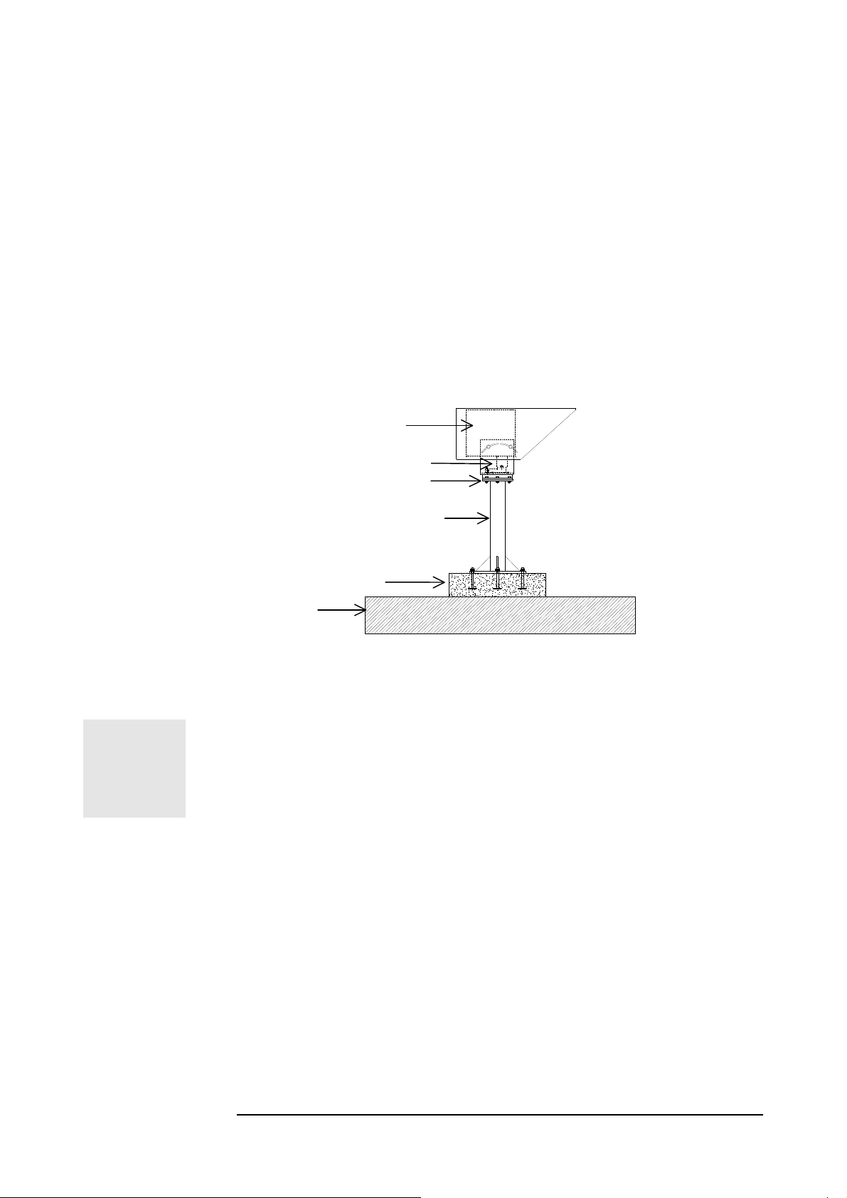
MRV Communications, Inc. – Installation Manual
Particular Figure Cases/Techniques
Mounting on the floor
In some cases the only place where the installation is acceptable, possible or
authorized is on the floor (for example on a roof without any parapet or if the
parapet is metallic ...). In such situations drilling holes on the floor is out of the
question.
The principle consists in fixing in a very stable way a tower standing on the floor.
The transceiver will be attached on the top of the tower.
Two techniques using a small concrete block are suggested for stabilizing the tower
on the floor.
• The concrete slab is directly poured on the basis of the tower
• Four bolts are inserted in the concrete slab placed on the floor. The tower
mount is fixed on the slab with the inserted bolts using nuts.
Transceiver
JAH
JMP
Tower Mount
Concrete Slab
Floor
Figure 5.12: Mounting on a concrete slab
TAKE CARE TO REMOVE ANY INTERVENING SOFT
MATERIAL, SUCH AS ASPHALT, BETWEEN THE SLAB/TOWER
BASIS AND THE FLOOR. ONCE THE INSTALLATION IS
COMPLETED RESTORE THE ROOF WATER-TIGHTNESS WITH
A SEALING MATERIAL AROUND THE SLAB.
45
Page 57
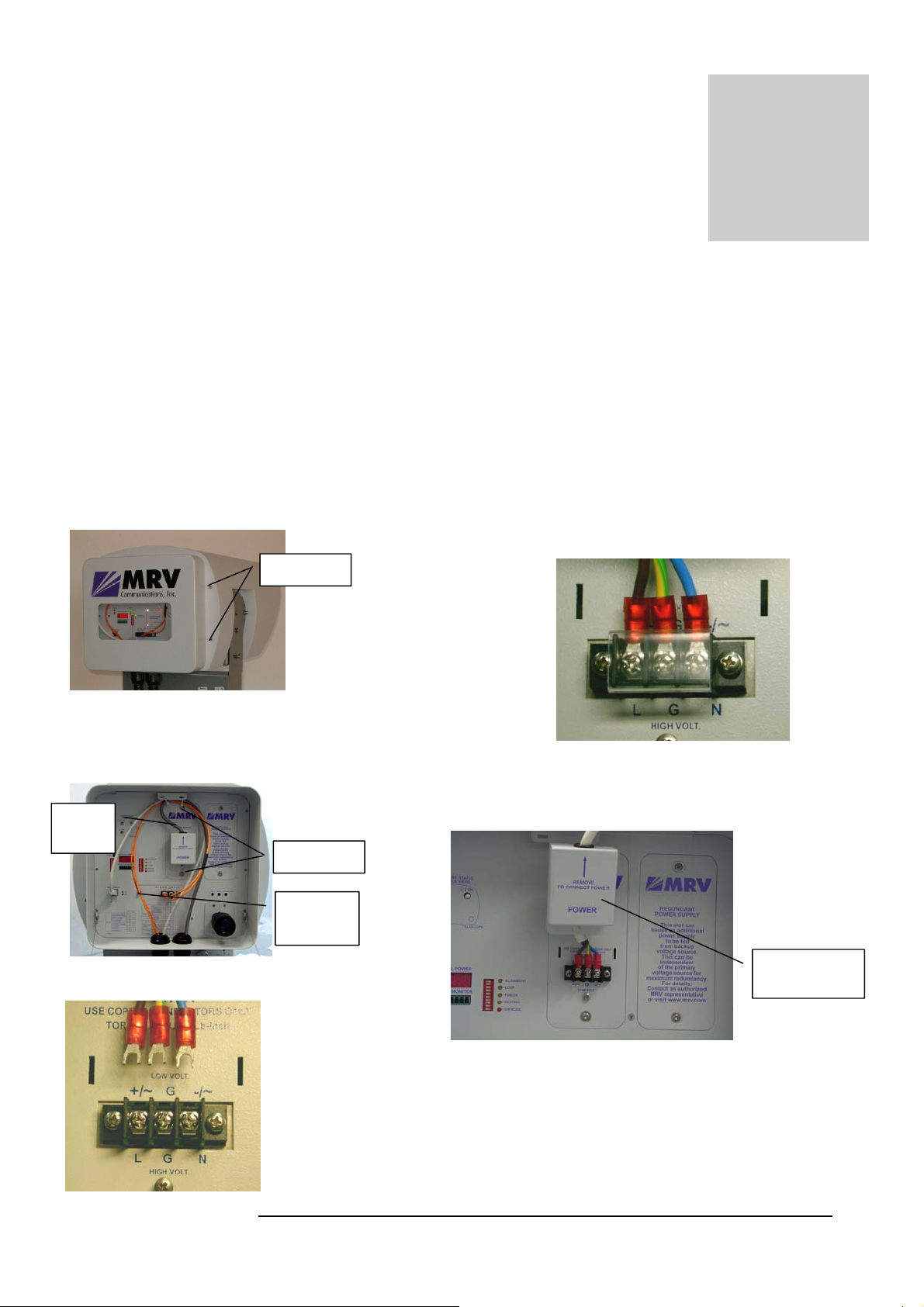
MRV Communications, Inc. – Installation Manual
g
y
Aiming Procedure
Point to point connections require the orientation face to face of both “transceiving” ends
of the link. Concerning wireless optical links this should be done as accurate as possible
for positioning the beam symmetrically all around the remote receiver.
Powering on the TereScope
1 – Make sure that the power cable is disconnected
from the electrical power source.
2 – Remove the Back Door by undoing the four
screws I (two on each side – see Figure 6.1.)
Fi
. 6.1: Screws I
3 – Connect the wires of the power cable (see Figure 6.2)
to the Terminal Block (see Figure 6.3) paying attention to
=
Power
Cable
Fig. 6.2: Power cable Fiberoptic cable, and ‘N’
Screws
=
'I' Screws
=
'N' Screws
Fiberoptic
Cable
Chapter
6
4 – After connecting the power cables to corresponding
sockets, tightly close the screws of the Terminal block –
see Figure 6.4. Gently jerk the cable to check that it stays
connected. Cover the Terminal Block with plastic cover (if
available).
5 – Cover the Terminal Block with the power supply
cover.
Fig. 6.4: Power Terminal Block Locked
Power Supply
Cover
Fig. 6.5: Power Suppl
6 – Connect the power cable to the electrical power
source to power on the TereScope.
Cover
Fig. 6.3: Power cable & Terminal block
46
Page 58
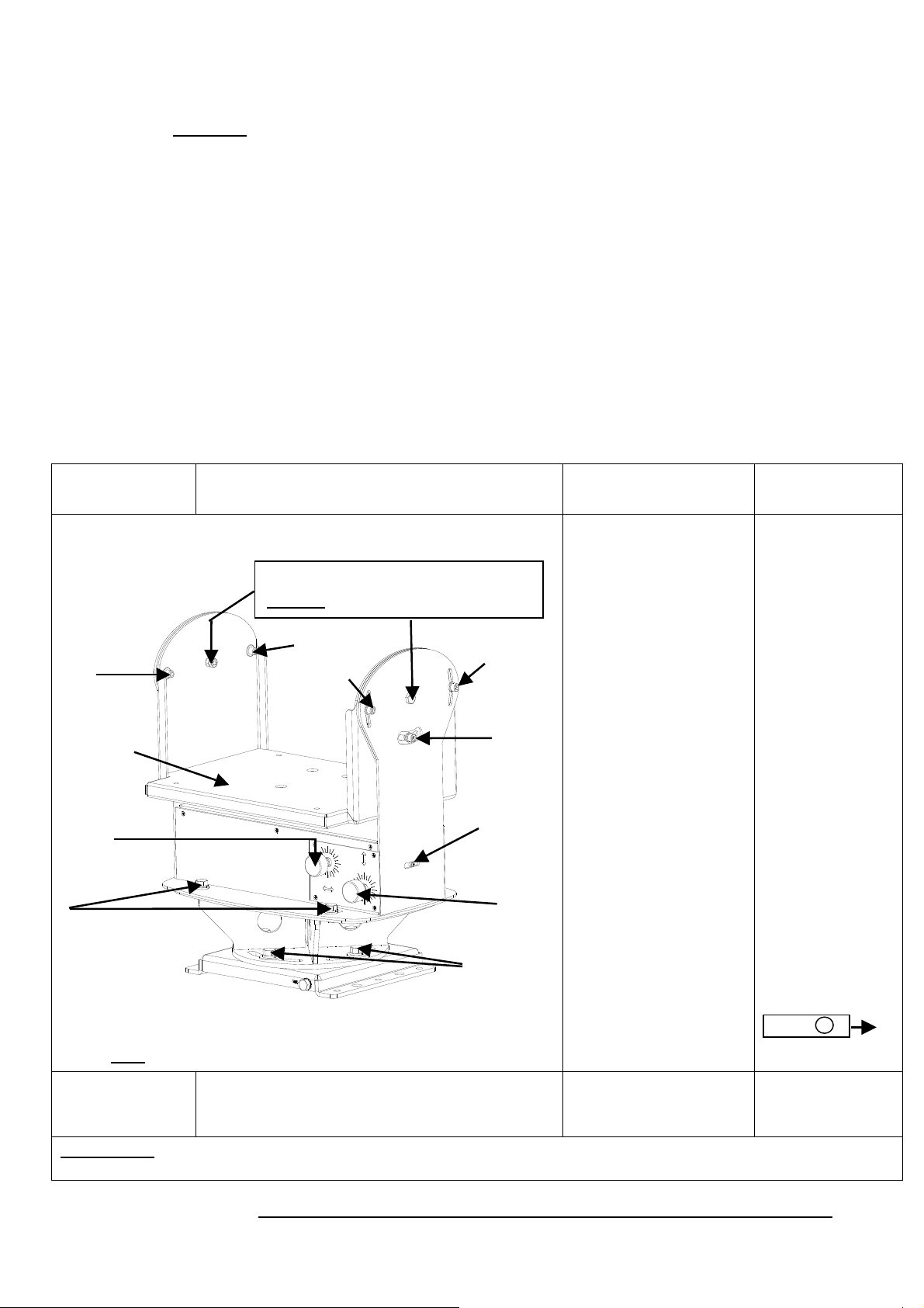
MRV Communications, Inc. – Installation Manual
Transceiver Alignment
Successful installation of the TereScope depends primarily on precise and accurate optical
alignment. Carefully follow the instructions below!!!
Important: Handle the Telescope with great care since it is the main tool for fine
alignment.
Turn on the power to the TS5000 heads from the power source.
Models G and G-F: Set DIP switch toggles 1,2 to the “Alignment” position (indicated on
the back panel).
Models 155 and 155-F: Set DIP switch toggles 1,2 to the “Alignment” position (indicated
on the back panel). If the installation distance is less than 900m it's recommended to
attenuate the signal for the alignment process, by pushing to ON position the toggle #3 of
dip-switch DS2. Caution: Switch back to OFF position for normal mode operation.
Models ETH and 4U1: Even if the data port is left unconnected, the TS5000 transmits
an Idle Signal which can be used to perform alignment.
The ttransceiver alignment procedure is implemented in two stages:
− Coarse Alignment
− Fine Alignment
Action Screws Position
Description Notes
1. Coarse
Alignment
J-L-2
Swing Base
B
E
All the screws are open (J, L, E, D)
K
Caution! Do not touch these screws.
J-L-3
-
-
J-R-3
L
M
(Red Ref.
Point)
C
D
4 Screws)
Fig 6.6: JMP-8 and AD-5000
Note: Knobs B and C are in the back of the TS5000.
Finishing
Screws D & L are closed.
coarse
alignment
CAUTION! Do not turn alignment knobs B and C when the fine horizontal aiming screws E and the
coarse vertical aiming screws J and L are locked since this may damage the fine alignment mechanism.
Rotate the transceiver
left and right, up and
down holding it by the
box and looking
through the telescope
till you can see the
opposite site. If the D
screws prevent further
rotation, screws D can
be reassembled in the
nearby holes.
If it is difficult to see
the opposite site due to
the distance or haze,
make sure at this stage
that the transceiver is
powered on and then
rotate the transceiver
to the right and to the
left, up and down,
moving it slowly till
the receipt of a certain
DVM reading
(minimum 20-30).
Tighten screws D & L.
Before starting
coarse alignment
ensure the
following:
1) Screws E are
positioned in the
middle of the
slots. This can be
done by turning
knob B.
2) The Red Ref.
point M is
positioned so that
its distance from
the movement
range end closer
to the front panel
is about 1/3 the
total movement
range. This can
be done by
turning knob C.
Front
(far side)
47
Page 59

MRV Communications, Inc. – Installation Manual
2. Fine
Alignment
3. Tightening
the Screws
4. Finishing
the
Alignment
E, J – opened.
L,D - closed
1) Open screws J-L-1,
J-L-2, and J-L-3 1 to
2 turns.
2) Tighten screws J-R-
1, J-R-2, and J-R-3 till
they are open for ¾
turns; i.e. slightly
tightened, but allow
for fine alignment.
3) Do the alignment
with the help of the
alignment knobs B &
C to place the opposite
Transceiver exactly in
the center of the target
of the telescope till
receipt of the signal on
RSSI meter.
4) Perform the fine
alignment procedure
given in the section
Fine Alignment on this
page (below).
1) Tighten screws E.
2) Tighten screws J-R-
2 and J-R-3 (2
screws).
3) Tighten screws J-L-
2, J-L-3, and J-L-1 (3
screws) in this order.
All screws are closed. To put down alignment
results – link distance;
-weather
condition;
-visibility;
-RSSI at both
sites.
Fine Alignment
• This stage requires one person on each site.
• Provide yourself with a walkie-talkie, a mobile phone or any other
equipment giving you a way to talk to the assistant working on the
opposite site.
The target at this stage is to aim only the local transmitter, using the Fine Tuning
the 2 knobs B and C, so that the remote receiver will be positioned in the middle
of the beam cross section at the shot distance.
V1
Figure 6.7:
Front view
Transceiver at the middle of
the beam cross section
H1
TereScope
48
V2
Beam Cross
Section
H2
Page 60
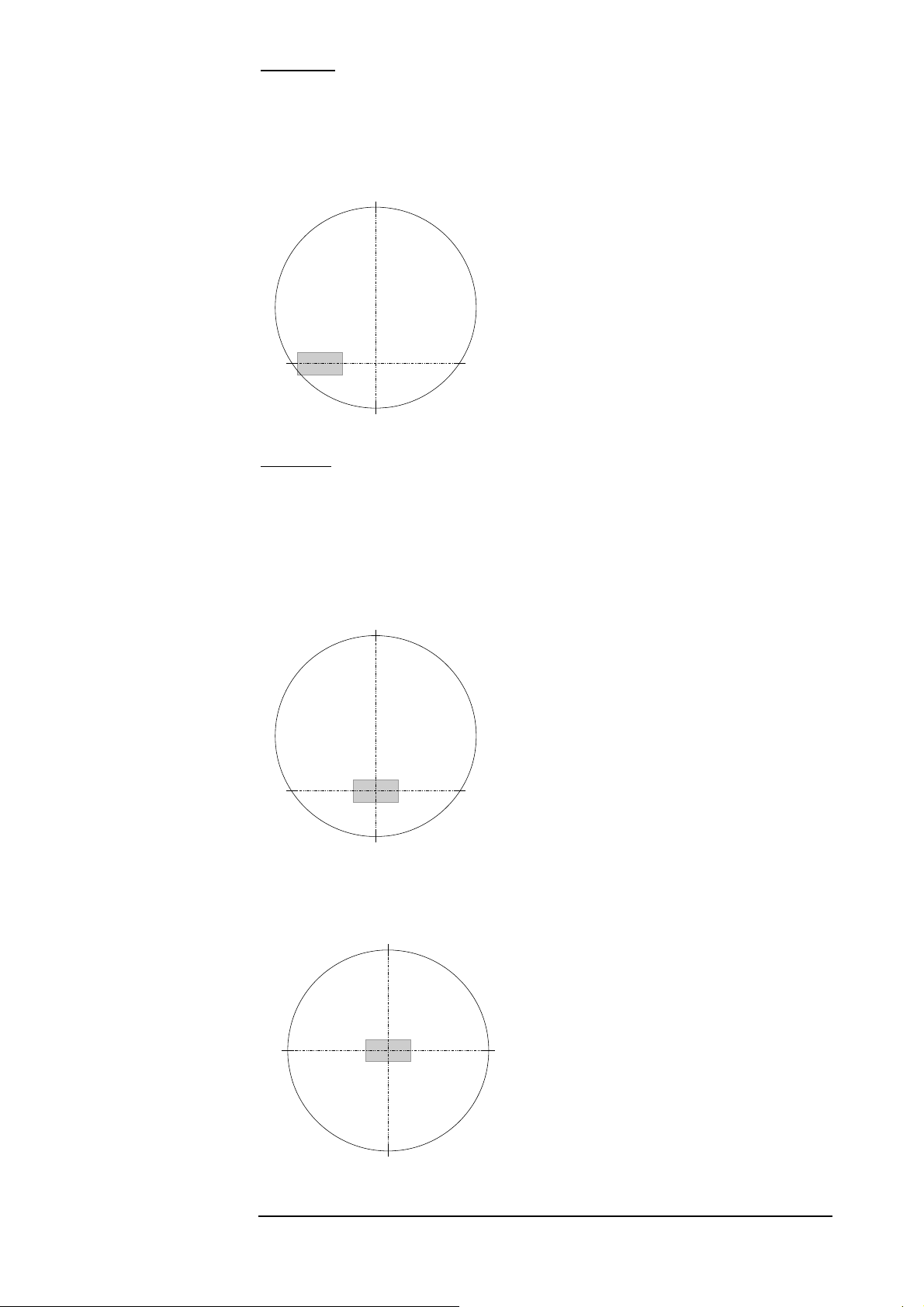
MRV Communications, Inc. – Installation Manual
Procedure:
1. Find the horizontal and vertical Beam edges (H1, H2, V1, V2) by
obtaining a reading between 200 and 300 on the 7-segment display.
2. Set successively the remote transceiver in the middle of
the two segments [H1, H2] and [V1, V2].
V1
Position at the beginning
(after the coarse alignment)
Position after the horizontal
aiming
H1 H2
Figure 6.8
Important: Do
V2
not
in all cases select the head position for which the DVM reading
is maximum! The best position of alignment is the beam center.
To determine the horizontal beam edges H1 and H2, move slowly left and right
the local transceiver until the digital readout on the remote unit becomes 200.
Locate these two points relating to reference points on the opposite site looking
through the telescope. Set the remote transceiver - moving the local transceiver - at
the middle of these two reference points.
V1
Final position after the
vertical aiming
H1 H2
Figure 6.9
V2
Repeat this process for the vertical positioning (middle of segment [V1,V2]).
V1
H1
V2
H2
Figure 6.10
49
Page 61

MRV Communications, Inc. – Installation Manual
Once the position is reached, firmly tighten the screws as described in Step 3 of the
section Transceiver Alignment on page 48.
Repeat this procedure exchanging roles with the assistant on the opposite
site (i.e. he will move the remote transceiver and you will report to him the
digital readout on the local one).
At the end of the process
the digital readout should
be approximately the same
on both units (see
Appendix B for expected
readings).
For short distances below or close to the minimum distance specified for
each model (see section Technical Specifications), pay attention that the
digital readout does not exceed 1200.
Caution: If the toggle #3 of DS2 is on 'ON' position, switch it back to 'OFF'
position for normal mode operation.
Link Operating Test
Set back the Mode Select Dip-Switch on the Normal position (the Alignment
indicator should switch OFF).
Connect on both sites with fiberoptic or STP cables coming from the peripheral
equipment to the fiberoptic or copper port of the transceiver.
IT IS A CROSS CONNECTION:
TX RX AND RX TX
The F/O RX Flag and Sync. Indicators should switch ON as soon as the
peripheral equipment is powered ON.
In the ETH model, the 10Base-T flag must turn ON and as soon as data traffic is
present, both DATA LEDs must blink.
In the 4U1 (4E1 or 4T1) model, the LED of a port must turn ON as soon as data
traffic is present on the port.
A BER test is recommended. In case this is not possible check at least with the
customer/user the performances of the whole link (see the chapter Bench Test).
Installation Log
Write down all the information about the installation (including digital readout and
the setup of the transceivers) in an installation log. This information is a valuable
reference for future maintenance or troubleshooting visits.
An example of an installation form is shown in Appendix H.
Before Closing the Rear Door
1. Ensure that the Power Supply Cover is fastened in place.
2. All cables are properly held in position.
50
Page 62
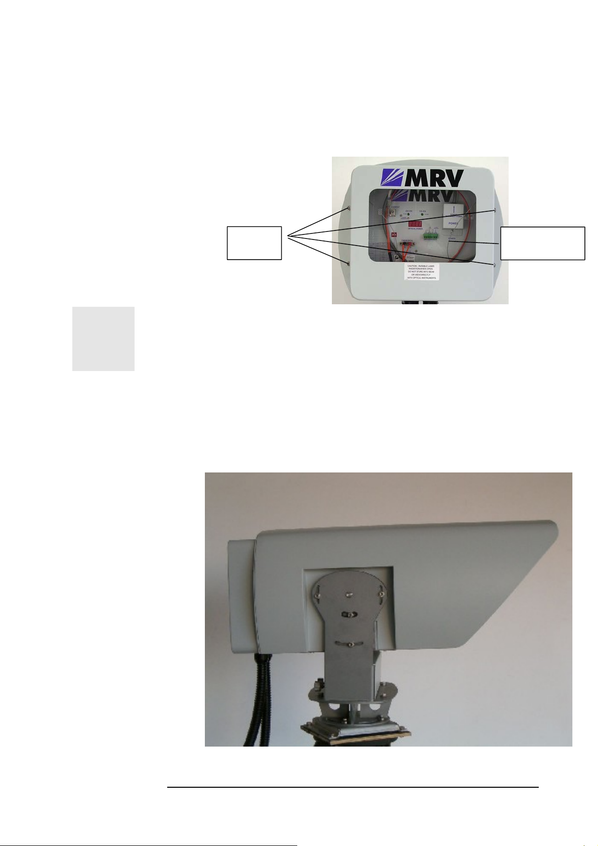
MRV Communications, Inc. – Installation Manual
Visual Inspection
Visually check that all parts and cables are connected.
Closing the rear door
Put back the Rear Door and push it. Close the four screws I -- see Figure 6.11.,
Pay attention to the cables holding the rear door.
.
Fig. 6.11: Closing the rear door,
Screws I
Connect to the Ground the 2 grounding screws (screw S from the
TereScope, and screw A from the JMP-8).
Captive
Screws I
Cables holding
the rear door
Installation Completion
Check that the heads appear as shown in the photographs below.
Fig. 6.12: Mounted TS5000 – Right View
51
Page 63
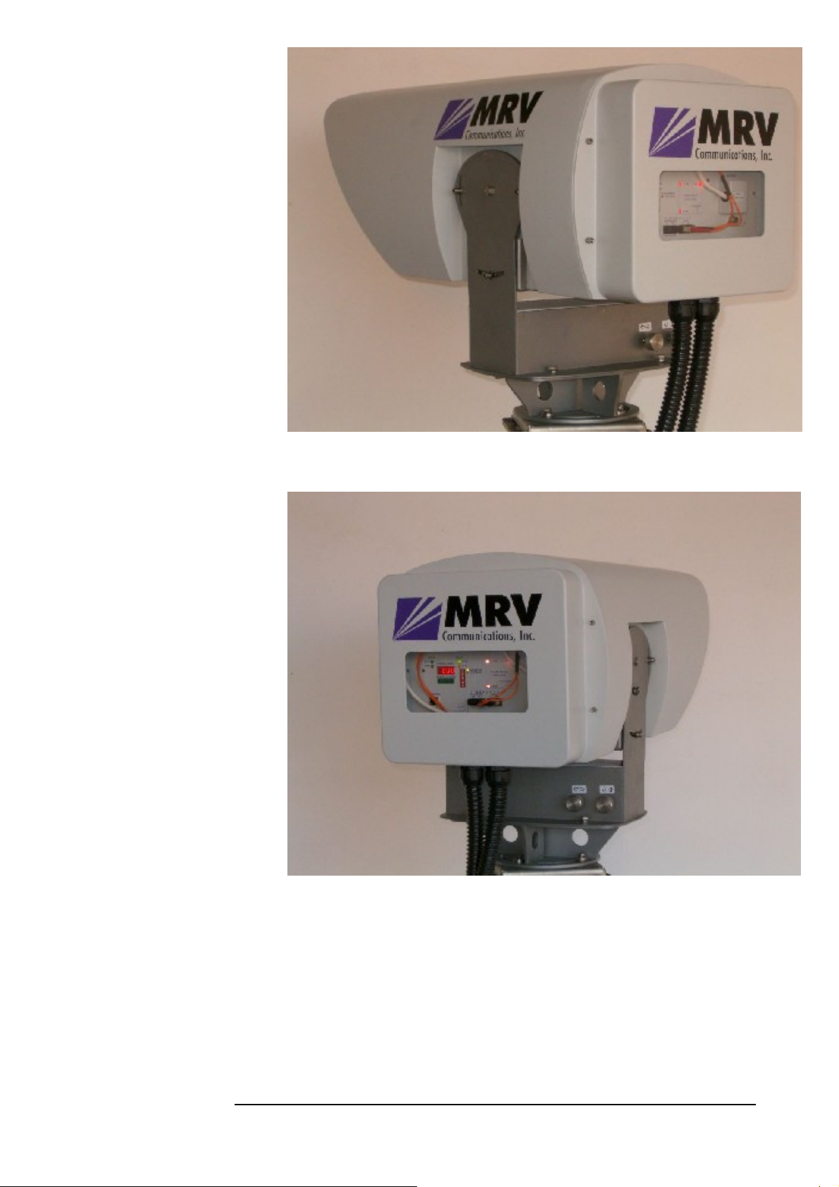
MRV Communications, Inc. – Installation Manual
Fig. 6.13: Mounted TS5000 – Left View
Fig. 6.14: Mounted TS5000 – Back View
52
Page 64

MRV Communications, Inc. – Installation Manual
Chapter
Maintenance
Periodic Visits
Periodic visits (every three/six months depending on the installation environment)
should be planned for:
• Checking the display
• Checking the mounting
• Cleaning the optical aperture of the transceivers
• Cleaning the building windows for indoors installations.
At cleaning time, the reading of the digital readout should be marked
down in a service log book. Once the optical aperture is cleaned, if
the reading is substantially lower than that noted at installation time,
the aiming accuracy should be examined and restored if necessary.
Note
Aiming accuracy should be checked looking through the telescope and comparing
the present scene sighting to the one sketched in the Installation Log at installation
time.
53
Page 65
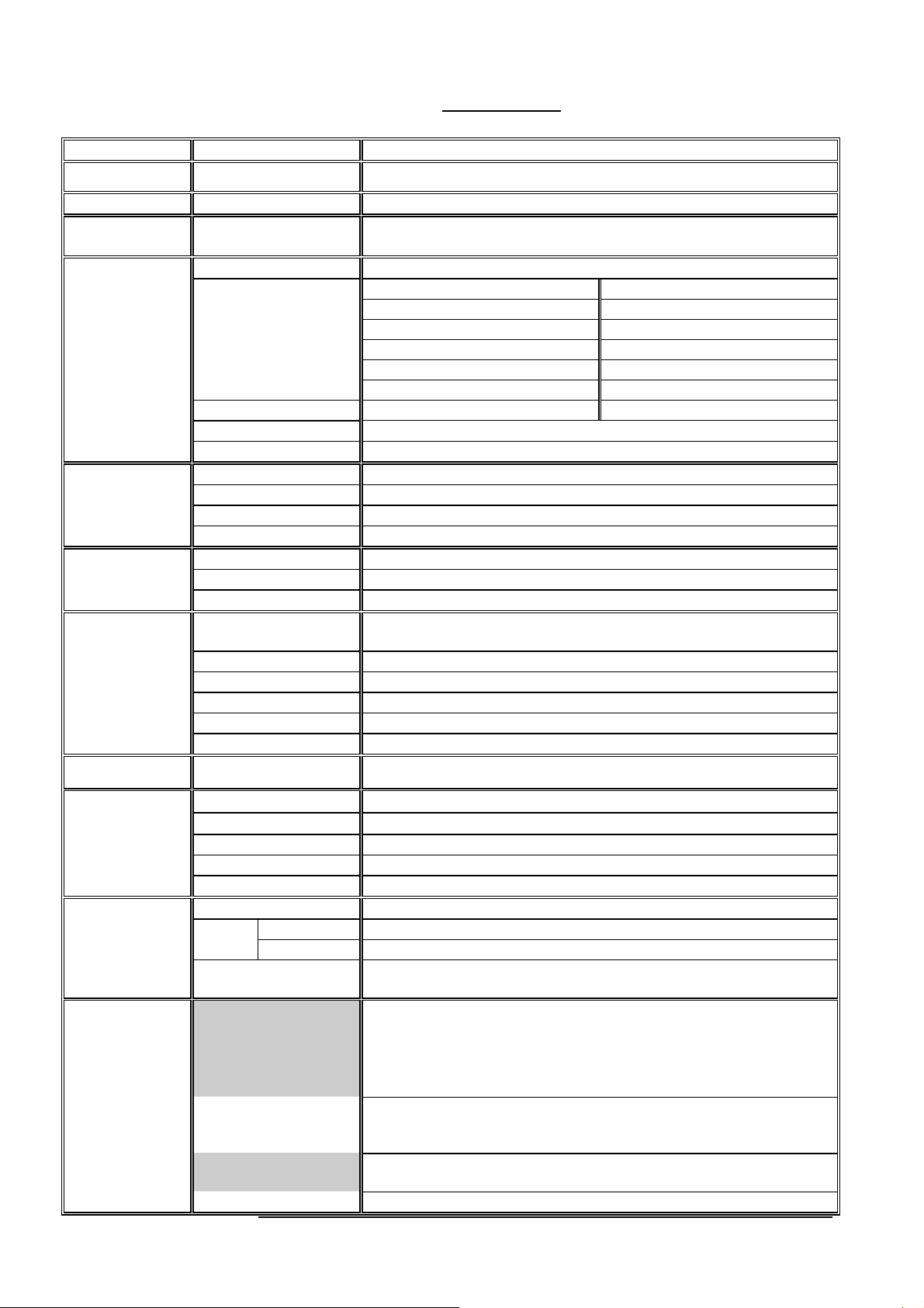
MRV Communications, Inc. – Installation Manual
APPENDIX A
Part Number
Model
Standard P.N
Application /
Data Protocol
Performance
Transmitter
Receiver
Interface
Power Supply
Environmental
Information
Mechanical
Design
Diagnostics
Indicators
and
Selectors
Rate 100-1500 Mbps
Range @ 3dB/km 3500 m 3100 m
@ 17dB/km 1300 m 1200 m
@ 30dB/km 870 m 820 m
Minimum Range 700 m 500 m
Bit Error Rate Less than 1E-12 (unfaded)
MTBF 10 years
Light source 3 x Lasers
Wavelength 830-860 nm
Total Output power 70 - 140 mW
Beam divergence 2 mrad
Detector APD
Field of view 5 mrad
Sensitivity -33 dBm
Type
Connectors SC (other connectors available)
Wavelength 850 nm (other wavelength available)
Output power -4 to -9.5 dBm
RX operating range 0 to –17 dBm
Built-in Fusion Optional
Operating Temp.
Storage Temp.
Humidity 95% non-condensing
Housing Weatherproof – IP 66
Eye safety Class 1M
Dimensions [mm] 790 X 390 X 556 (AD-5000: 250x353x432)
Modularity
Indicators Airlink: Flag, Sync. Fiber Optic: Flag, Sync.
Selectors
Dry Contact
Management SNMP Protocol – Built-in
Product Specifications
TS5000/G
TS5000G/XXX/V** or T S5000G/XXX/ F* *
TS5000/G or TS5000/G-F
TS5000G/M8C/V1S
Escon, 622Mbps, Fiber channel, Giga-Ethernet and
others between 100 and 1500Mbps
Not attenuated (3 TXs) Attenuated (2 TXs)
@ 5dB/km 2750 m 2500 m
@ 10dB/km 1850 m 1650 m
Fiber Optic Transceiver - Multimode (Single mode available upon
request)
Factory set: 100-240 VAC @ 50/60 Hz or 35-60 VDC (V3 and F3 versions)
Unit 14 kg Weight
Accessories 21.5Kg
Modular Power supply, Modular Interface,
Redundant Power supply - optional
Alignment, Loopback, Fusion: Enabled/Active, Heating status (if
exists), Control mode: Hardware mode or software mode.
Power supply status, Heating active, Receive Signal Strength
(Digital Display), Lasers status (3 LEDs), SNMP TX and RX
Alignment, Loopback (local), Remote Loopback, Fusion
activation, Signal attenuation for Short distance, Heating activation
(if exists), IP address setup, Control mode.
Two pairs of Pins of the management RJ45 connector can be
used for dry contact purposes, for Airlink flag and F/O flag alarms
54
(30 W)
-30 °C to +60 °C
-50 °C to +70 °C
Page 66

MRV Communications, Inc. – Installation Manual
Part Number
Model
Standard P.N
Application /
Data Protocol
Performance
Transmitter
Receiver
Interface
Power Supply
Environmental
Information
Mechanical
Design
Diagnostics
Indicators
and
Selectors
Rate 1-155 Mbps
Range @ 3dB/km 5400 m
@ 17dB/km 1820 m
@ 30dB/km 1185 m
Minimum Range 450 m
Bit Error Rate Less than 1E-12 (unfaded)
MTBF 10 years
Light source 3 x Lasers
Wavelength 830-860 nm
Total Output power 85 mW
Beam divergence 2 mrad
Detector APD
Field of view 2 mrad
Sensitivity -46 dBm
Type
Connectors SC (other connectors available)
Wavelength 1310 nm (other wavelength available)
Output power
RX operating range -14 to –30 dBm
Built-in Fusion Optional
Operating Temp.
Storage Temp.
Humidity 95% non-condensing
Housing Weatherproof – IP 66
Eye safety Class 1M
Dimensions [mm] 790 X 390 X 556 (AD-5000: 250x353x432)
Modularity
Indicators Airlink: Flag, Sync. Fiber Optic: Flag, Sync.
Selectors
Dry Contact
Management SNMP Protocol – Built-in
TS5000/155 and TS5000/155-F
TS5000/XYZ/V** or TS5000/XYZ/F**
TS5000/155 or TS5000/155-F
TS5000/M3C/V1S
Fast Ethernet, ATM, OC3,STM1, SMPTE, E3, T3, OC1/STM0 &
Open Protocol
@ 5dB/km 4080 m
@ 10dB/km 2650 m
Fiber Optic Transceiver - Multimode (Single mode available upon
request)
-17 ± 3 dBm
Factory set: 100-240 VAC @ 50/60 Hz or 35-60 VDC (V3 and F3 versions)
Unit 14 kg Weight
Accessories 21.5kg
Modular Power supply, Modular Interface,
Redundant Power supply - optional
Alignment, Loopback, Fusion: Enabled/Active, Heating status (if
exists), Control mode: Hardware mode or software mode.
Power supply status, Heating active, Receive Signal Strength
(Digital Display), Lasers status (3 LEDs) ), SNMP TX and RX
Data Rate, Alignment, Loopback (local), Remote Loopback,
Laser status, Fusion activation, Heating activation (if exists), IP
address setup, Control mode.
Two pairs of Pins of the management RJ45 connector can be
used for dry contact purposes, for Airlink flag and F/O flag alarms
(30 W)
-50 °C to +60 °C
-50 °C to +70 °C
55
Page 67
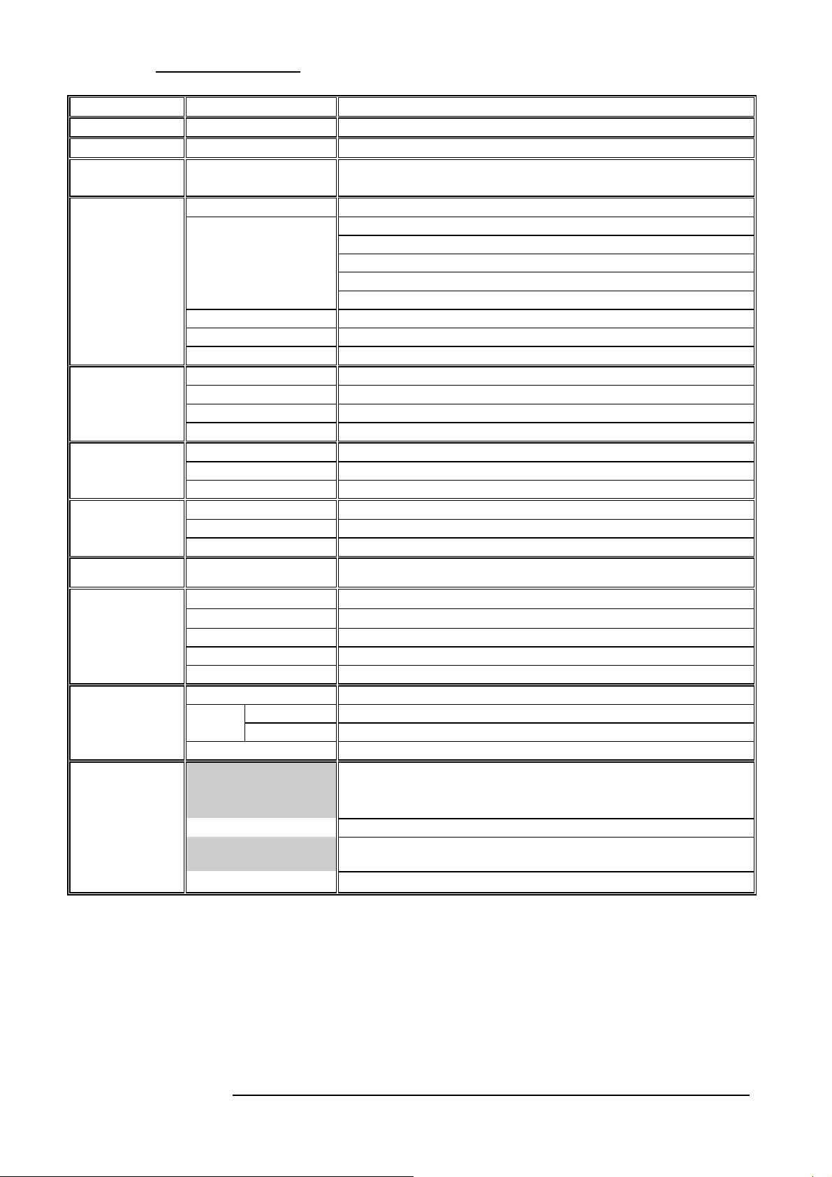
MRV Communications, Inc. – Installation Manual
TS5000/ETH
Part Number
Model
Standard P.N
Application /
Data Protocol
Performance
Transmitter
Receiver
Interface
Power Supply
Environmental
Information
Mechanical
Design
Diagnostics
Indicators
and
Selectors
Rate 10Mbps
Range
@ 17dB/km 2170 m
@ 30dB/km 1400 m
Minimum Range 400 m
Bit Error Rate Less than 1E-9 (unfaded)
MTBF 10 years
Light source 3 x Lasers
Wavelength 830-860 nm
Total Output power 85 mW
Beam divergence 2 mrad
Detector APD
Field of view 2 mrad
Sensitivity -55 dBm
Type Copper 10BaseT
Connectors RJ45
Cable STP
Operating Temp.
Storage Temp.
Humidity 95% non-condensing
Housing Weatherproof – IP 66
Eye safety Class 1M
Dimensions [mm] 790 X 390 X 556 (AD-5000: 250x353x432)
Modularity Modular Power supply
Indicators Airlink: Flag, Data. 10Base-T: Flag, Data.
Selectors IP address setting
Dry Contact
Management SNMP Protocol – Built-in
TS5000/ETH/V*
TS5000/ETH
TS5000/ETH/VS
Ethernet (10 Mbps)
(1)
@ 3dB/km 6700 m
@ 5dB/km 5000 m
@ 10dB/km 3200 m
Factory set: 100-240 VAC @ 50/60 Hz or 35-60 VDC (V3 Version)
Unit 14 kg Weight
Accessories 21.5kg
Receive Signal Strength (Digital Display),
Lasers status (3 LEDs)
One pair of Pins of the main RJ45 connector can be used for
dry contact purposes, for Airlink flag alarm
(30 W)
-30 °C to +50 °C
-50 °C to +70 °C
56
Page 68
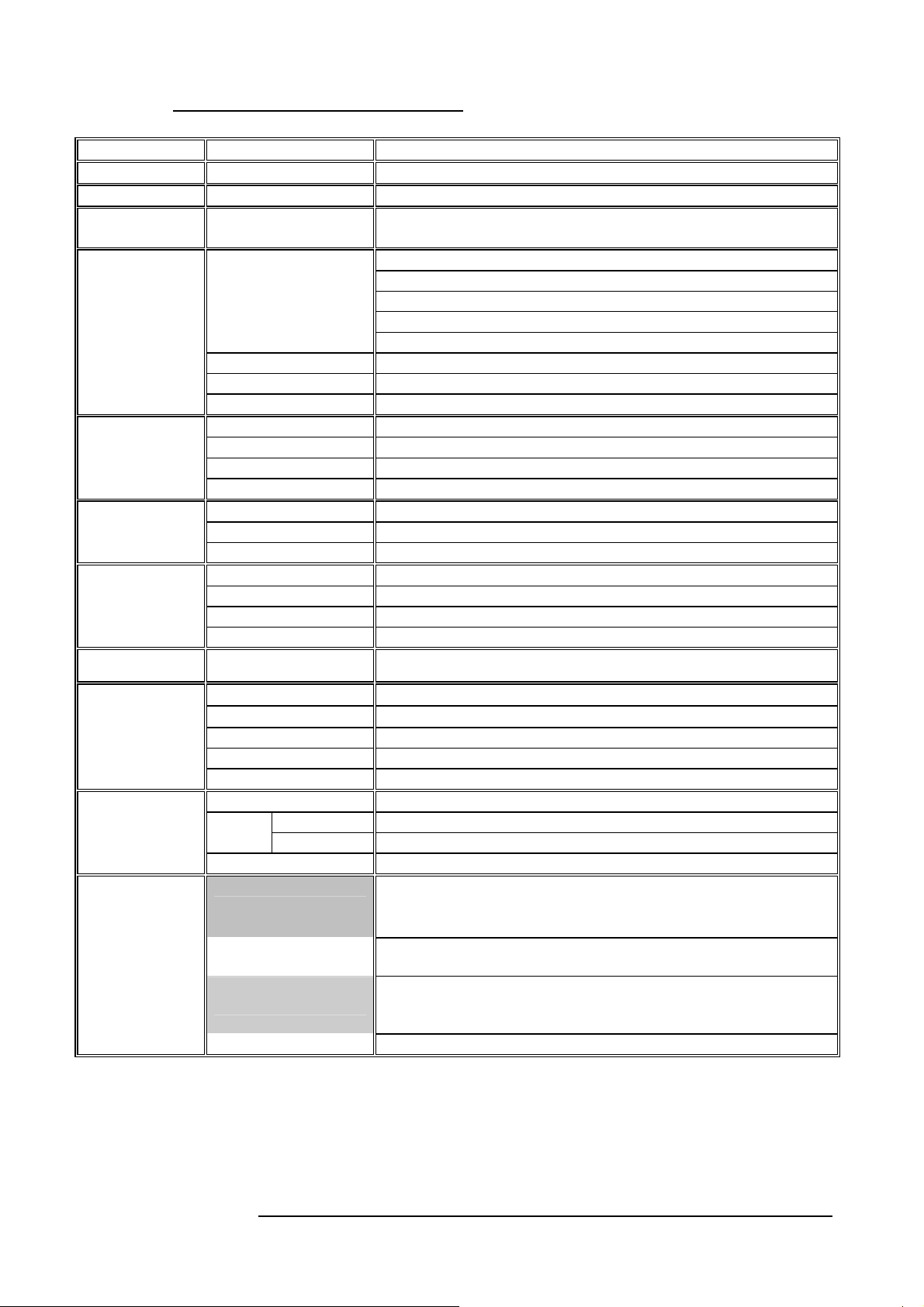
MRV Communications, Inc. – Installation Manual
TS5000/4U1 (4E1 or 4T1)
Part Number
Model
Standard P.N
Application /
Data Protocol
Performance
Transmitter
Receiver
Interface
Power Supply
Environmental
Information
Mechanical
Design
Diagnostics
Indicators
and
Selectors
Range @ 3dB/km 6700 m
@ 17dB/km 2170 m
@ 30dB/km 1400 m
Minimum Range 400 m
Bit Error Rate Less than 1E-9 (unfaded)
MTBF 10 years
Light source 3 x Lasers
Wavelength 830-860 nm
Total Output power 85 mW
Beam divergence 2 mrad
Detector APD
Field of view 2 mrad
Sensitivity -55 dBm
Type Electrical: E1: 75 Ohm or 120 Ohm, T1: 100 Ohm
Connectors Universal Connector
Cable STP or Coax
Cable Losses Supports Short and Long haul trunks
Operating Temp.
Storage Temp.
Humidity 95% non-condensing
Housing Weatherproof – IP 66
Eye safety Class 1M
Dimensions [mm] 790 X 390 X 556 (AD-5000: 250x353x432)
Modularity Modular Power supply
Indicators Airlink: Flag, Sync. E1 Ports: LED per port.
Selectors
Dry Contact
Management SNMP Protocol – Built-in
TS5000/4E1/V* or TS5000/4T1/V*
TS5000/4E1 or TS5000/4T1
TS5000/4E1/VS
4E1: 4x2.048Mbps or 4T1: 4x1.55Mbps
G.703/G.704
@ 5dB/km 5000 m
@ 10dB/km 3200 m
Factory set: 100-240 VAC @ 50/60 Hz or 35-60 VDC (V3 Version)
(30 W)
-30 °C to +50 °C
-50 °C to +70 °C
Unit 14 kg Weight
Accessories 21.5kg
Receive Signal Strength (Digital Display),
Lasers status (3 LEDs)
Termination, Electrical receive sensitivity, Line incoding, Local
Loopback, Remote Loopback, IP address setting
6 Dry Contact outputs: 4 for interface ports
1 for air-link flag
1 for air-link sync
57
Page 69
MRV Communications, Inc. – Installation Manual
APPENDIX B
TS5000/G and
TS5000/G-F
TS5000/155 and
TS5000/155-F
Rev 3.0 and less
D
R
D
R
D
R
D
R
Digital Readout vs. Distance
These tables are only intended to give you an idea of what digital readout you could
expect according to the distance to link.
D= Distance [m]
R= Reading (Digital readout)
400 500 600 700 800 900 1000 1100 1200 1400 1500
1100 950 820 700 780 700 620 560 500 440 380
1600 1800 2000 2200 2400 2600 2800 3000 3500 4000
360 280 240 220 180 160 135 125 95 75
600 800 1000 1200 1400 1600 1800 2000
1050 1000 940 880 840 830 810 800
2200 2400 2600 2800 3000 3500 4000 5000
790 780 760 750 740 720 680 580
TS5000/155 and
TS5000/155-F
TS5000/ETH and
TS5000/4U1
(4E1 or 4T1)
D
400 500 600 700 800 900 1000 1100 1200 1400 1500 1600 1800 2000
R
1270 1250 1070 1020 990 970 950 940 930 920 910 890 840 780
D
R
2200 2400 2600 2800 3000 3500 4000 4300 4600 5000 5300 5600 6000
730 680 650 630 570 530 490 465 450 440 420 410 390
400 500 600 700 800 900 1000 1100 1200 1400 1500 1600 1800 2000
D
1220 1220
R
D
R
2200 2400 2600 2800 3000 3500 4000 4300 4600 5000 5300 5600 6000
590
630
1040 990 920 870
1150
540 510
570
800 720
850
470 430 410 390 360 350 330 320
705 700 670
710
Actual reading may be greater or up to 15% lower.
Even when there is no transmission from the opposite side, the digital readout of
TS5000 can show a certain reading: up to 5-6 in laboratory and up to 20 outside.
58
Page 70
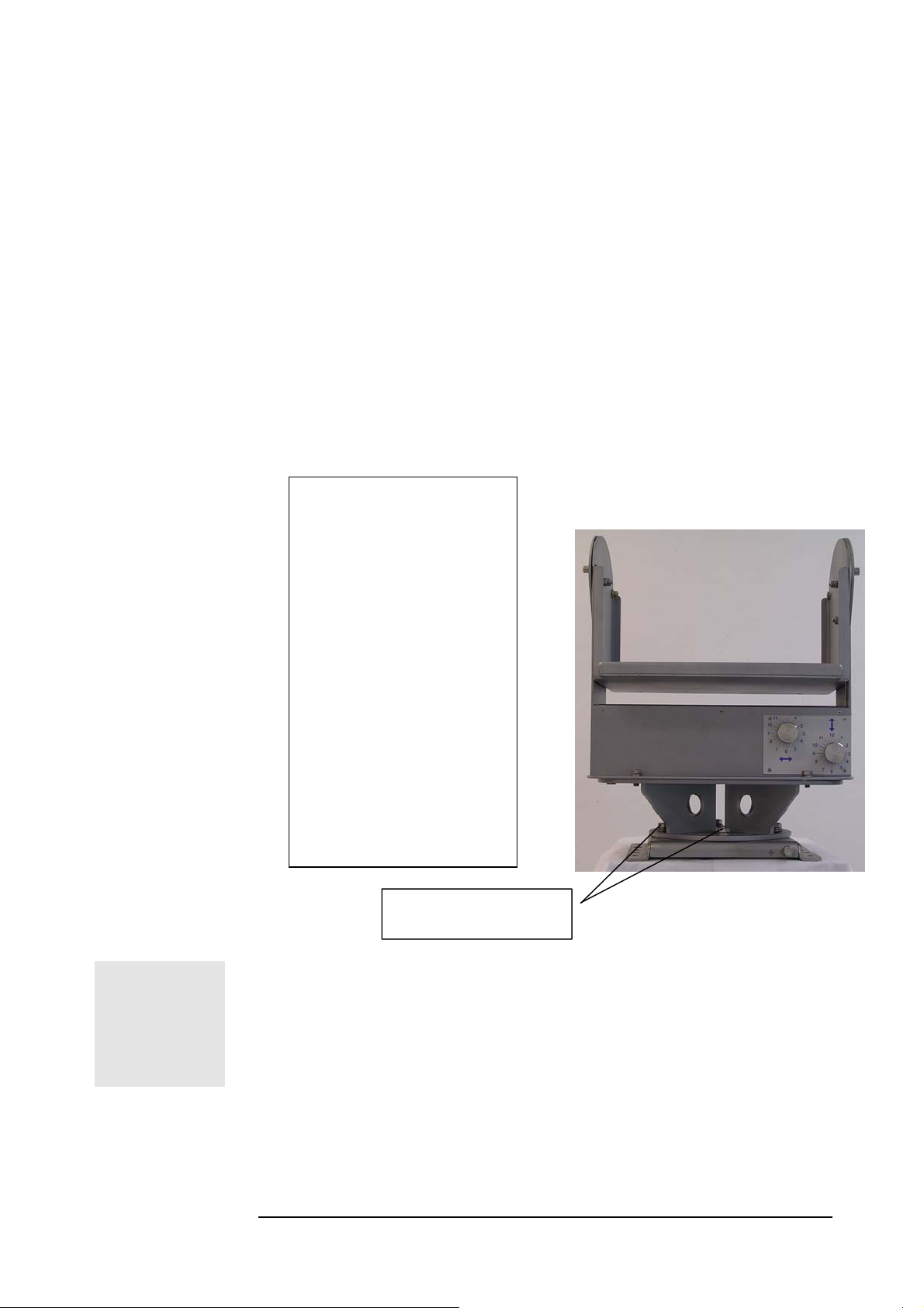
MRV Communications, Inc. – Installation Manual
APPENDIX C
Unpacking Instructions for TS4000/5000
The JMP-8 is shipped assembled to the AD-5000, inside the accessories packing
box. It must be dismantled prior to installation.
1. Unpack all the accessories.
2. Loosen completely the four ‘D’ (M8 hex. screws, using
wrench #13 and take the AD-5000 off the base JMP-8
(Save the screws for later use). Do not attempt to loosen or
tighten any screws on the AD-5000 other than those
specified in this manual.
The packing box
contains:
• Big box with one
Transceiver
TS4000/5000
• Smaller box with
accessories:
♦ AD-5000 &
JMP-8
♦ JITK – Installer
tools kit and
screws
♦ CD manuals
♦ Flexible ducts x 2
♦ Flange x 2
‘D’ Screws
(Two in front, two behind)
KEEP IN SECURE PLACE ALL THE BOLTS AND SCREWS. YOU
WILL NEED THEM FOR THE INSTALLATION.
59
Fig C.1: The Four ‘D’ Screws
Page 71

MRV Communications, Inc. – Installation Manual
APPENDIX D
TOOLS
Tool Kit, Equipment and Materials
1. Electric drill (impact for masonry), reversible, with
speed control and 0-13mm chuck
2. Drills set High Speed Steel (HSS) 3-13mm.
3. Concrete carbide .bit drills 6,8,9 and 10mm (regular
and long shank).
4. Adjustable (crescent) wrench 6”, 10”.
5. Open-ring wrenches (spanners), standard and metric.
6. Vice grip pliers 10-12”
7. Cutter, long nose pliers, electrician’s pliers (insulated).
8. Pen, Pencil, Permanent markers.
9. Lens cleaning clothes.
10. Screwdrivers (flat and Philips), sizes 1, 2, 3 + power
screwdriver bits.
11. 50m extension cable + 3 outlet multiple electrical tap
12. 200g hammer.
13. Blade knife.
MATERIALS
ELECTRONIC &
GENERAL
EQUIPMENT
14. Ratchet handle driver.
15. Socket wrenches 8mm, 10mm, 11mm, 13mm, 14mm,
½” .
16. MRV JITK, see next page for details.
1. Anchors (wall plugs) “UPAT” 13mm diameter
2. Hex-head screws to fit wall plugs 40, 60, 75mm length.
3. Assortment of screws, nuts, washers, spring washers.
4. Electric insulation tape.
5. Super glue, tie wraps (Panduit™).
6. 20 mm fuse SB, 125mA, 160mA, 250mA,
500mA, 1A
1. Digital voltmeter (DVM)
2. 2 Walkie Talkies or cellular phones.
3. Binoculars
4. Four STP cables (two cross and two straight)
terminated with RJ-45 connectors each end.
OPTICAL
EQUIPMENT
(if relevant)
LAB EQUIPMENT
1. Optical Power Meter (Fotec, Noyes, Acterna…)
with fiber sockets.
2. 2 sets of multimode (62.5 µm) and Singlemode
(15µm) optical fibers with SC terminations.
E1/ETH/ATM/Fast Ethernet BER Test equipmentdepending on TS model.
60
Page 72

MRV Communications, Inc. – Installation Manual
A LIST OF THE TOOLS SUPPLIED BY MRV COMMUNICATIONS
WITH EVERY TS4000/5000 HEAD
Description Qty Where to use
a
.
b
.
c
.
d
.
WRENCH #10 FOR M6
SCREW
WRENCH #13 (M8
SCREW)
WRENCH # 9/16”
(SCREW 3/8”) 1
BALLDRIVER L
(WRENCH 5 MM)
e. BALLDRIVER L,
WRENCH 3mm
f
.
g
.
M8 SCREW, WASHER,
SPRING, NUT
INSTALLATION
TOOL CASE
1
1
H: AD-5000 to TereScope box
E: JMP-8 - Horizontal Aiming
Locking screws
D: Locking screws between the
alignment device AD-5000 &
base plate JMP-8
1
1
J-R, J-L, L: Vertical aiming
locking screws
I: Rear Door Screws (x4)
4
1
Wrenches Kit for TS Installation
Optional. To mount AD-5000
on standard pedestal
Tool case
61
Page 73

MRV Communications, Inc. – Installation Manual
APPENDIX E
TereScopes Bench Test Procedure
Introduction
All TS Products are bench tested indoors prior to outdoor
installation to ensure that the system is fully functional.
The bench test is a simple procedure whereby a link pair is aligned
on the table and activated to simulate a channel of communication
(see fig.1).
2 Points to Remember
1. Since the link distance during the bench test is very short (i.e. the
devices activated are very close), the receivers will go into saturation
unless the signal is attenuated.
To avert entering saturation, the transmit signal must be physically
attenuated.
We recommend the simple procedure of inserting a piece of paper
or the like into the beam path, or concealing a portion of the beam
with an opaque (non-transparent) material. This will reduce the
signal power entering the receiver.
Make sure to attenuate the signal enough so that the receiver’s
optical power meter value falls below the saturation estimate of the
device. See table below for saturation estimate.
2. An additional derivative of the short link distance is the presence
of reflections.
The signal will reflect off the front window of the receiver back at
the transmitting device and may be mistaken as part of the opposite
transmission.
This interference is commonly called “cross talk”.
To avoid cross talk during the bench test, it is advisable to check
whether interfering reflections exist by shutting off power to one
device and verifying that the optical power meter reading in the
other (active) device is zero.
This should be repeated for the opposite device.
Alternatively, a practical setup for bench testing the 4” series
(models B, C and D) and Light series (models A and C2) is
presented in Figure 1; the bench test setup for the 10” series
(models E and F) is presented in Figures 2a,2b.
In the 4”/Light setup, a thin physical barrier, such as a piece of
cardboard, is used as a wall to divide between the beam paths, thus
ensuring that no cross talk occurs.
In the 10” setup, the two devices are not centrally aligned; instead,
only one corner of each device faces the opposite device. This
allows for testing each transmitter separately. By rotating the devices
45 degrees, the next pair of transmitters is tested. Hence, testing all
8 transmitters in the link pair requires only 4 rotations.
62
Page 74
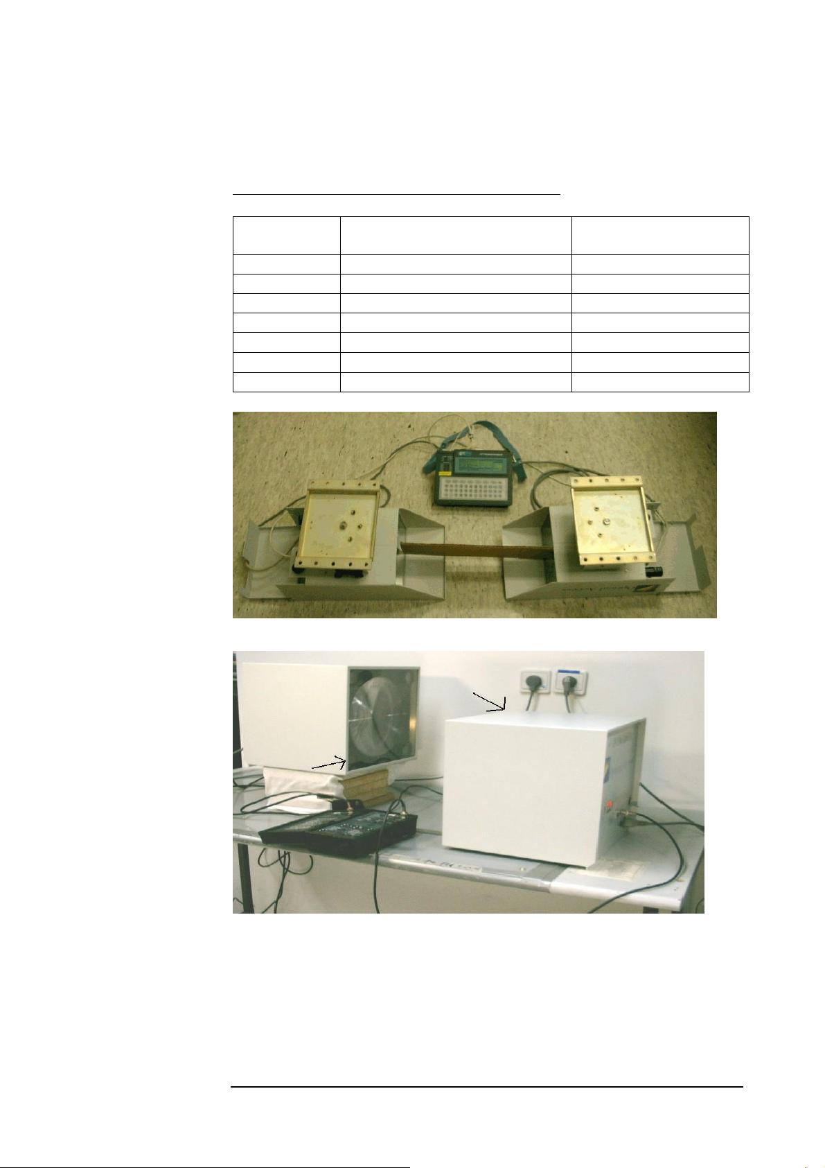
MRV Communications, Inc. – Installation Manual
In the 8” setup, the two devices are not centrally aligned; instead,
only one corner of each device faces the opposite device. This
allows for testing each transmitter separately. By rotating the devices
45 degrees, the next pair of transmitters is tested. Hence, testing all
6 transmitters in the link pair requires only 3 rotations. With opaque
masking tape, cover all transmitters that are not under test.
Table 1: Bench Test Information for TS Products
Product name
Opt. Power M. “Sub-Saturation”
value
Potential for
Interference
TSxxxx 1100 Low
TSxxx/ETH 1200 Med
TSxxx/E1 1200 High
TSxxxx/ST 1200 Med
TS2000/XXX 1100 High
TS4000/XXX 1200 High
TS5000/XXX 1000 High
Figure E.1: Bench Test setup for 4”/Light TS models.
Figure E.2a: Bench Test setup for 10” TS model; transmitter aligned opposite receiver
marked with arrows.
63
Page 75
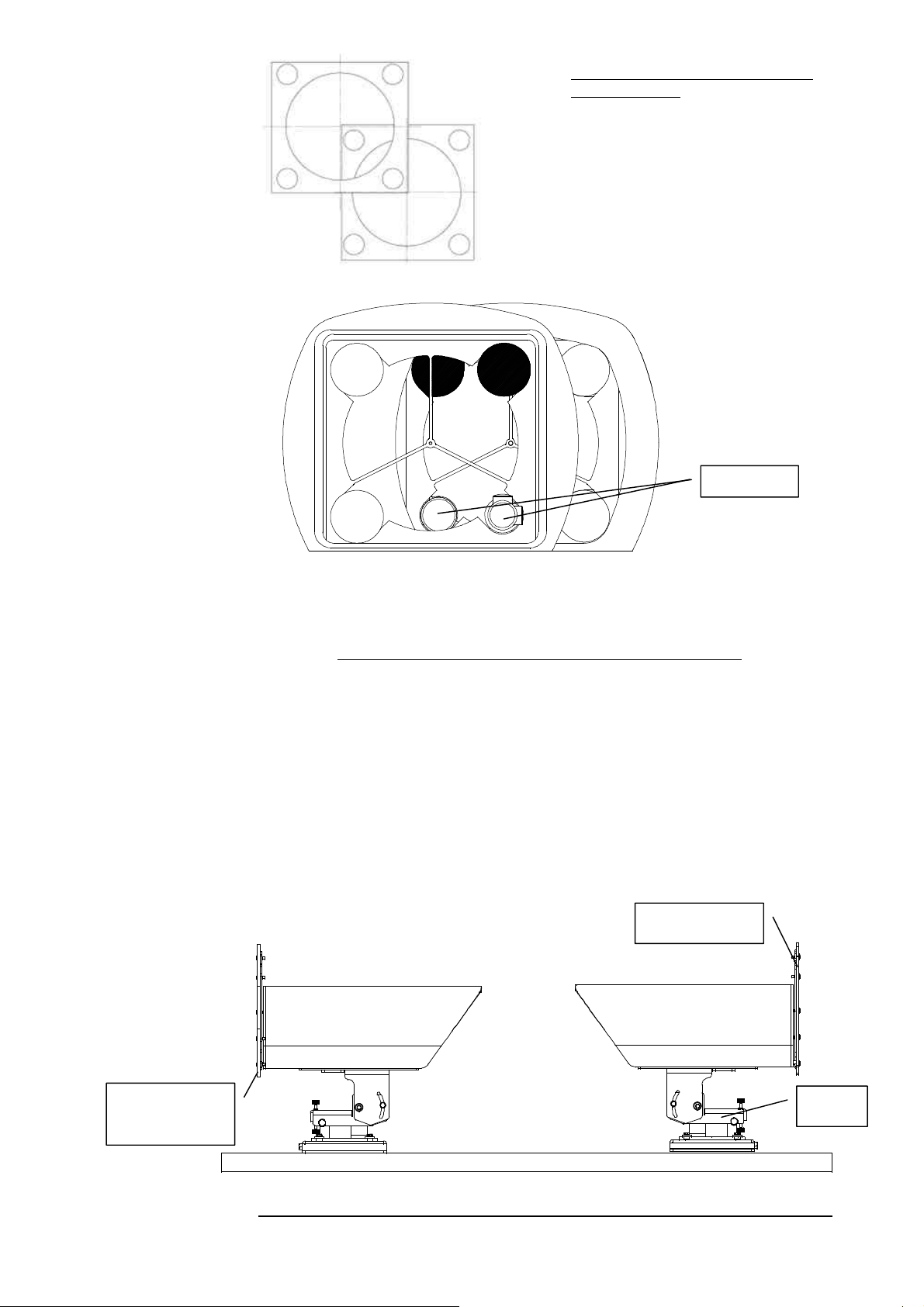
MRV Communications, Inc. – Installation Manual
T
T
p
J
Figure E.2b: Bench Test setup drawing
for 10” TS model.
Note that one device is higher than the
other and shifted over to the side so that
only one transmitter from each device is
facing opposite the other device’s receiver.
he Rear Door
hangs over the
ereSco
e basis
Telescopes
Figure E.3: Active Transmitters (Shown Darkened).
Bench Test for TS700 and TS800 series with JAH-L
The Aiming head of the TS700 and TS800 series was changed from AD-700
to JAH-L.
Therefore the TereScopes are delivered to the clients not mounted on the
Aiming head. In this case, when the back door is opened and secured in its
place, it hangs over the TereScope basis and the TereScope can’t stand straight
and leans on the door, which can damage the door’s hinges.
Therefore there are two ways to perform the Bench test, as can be seen on the
following figures.
The first way is to mount the TereScope on its Aiming head and do all the
tests before installation with the alignment head.
Rear Door fixed
AH-L
Figure E.4: Bench test with TereScopes mounted on the Aiming Head (JAH-L.)
64
Page 76
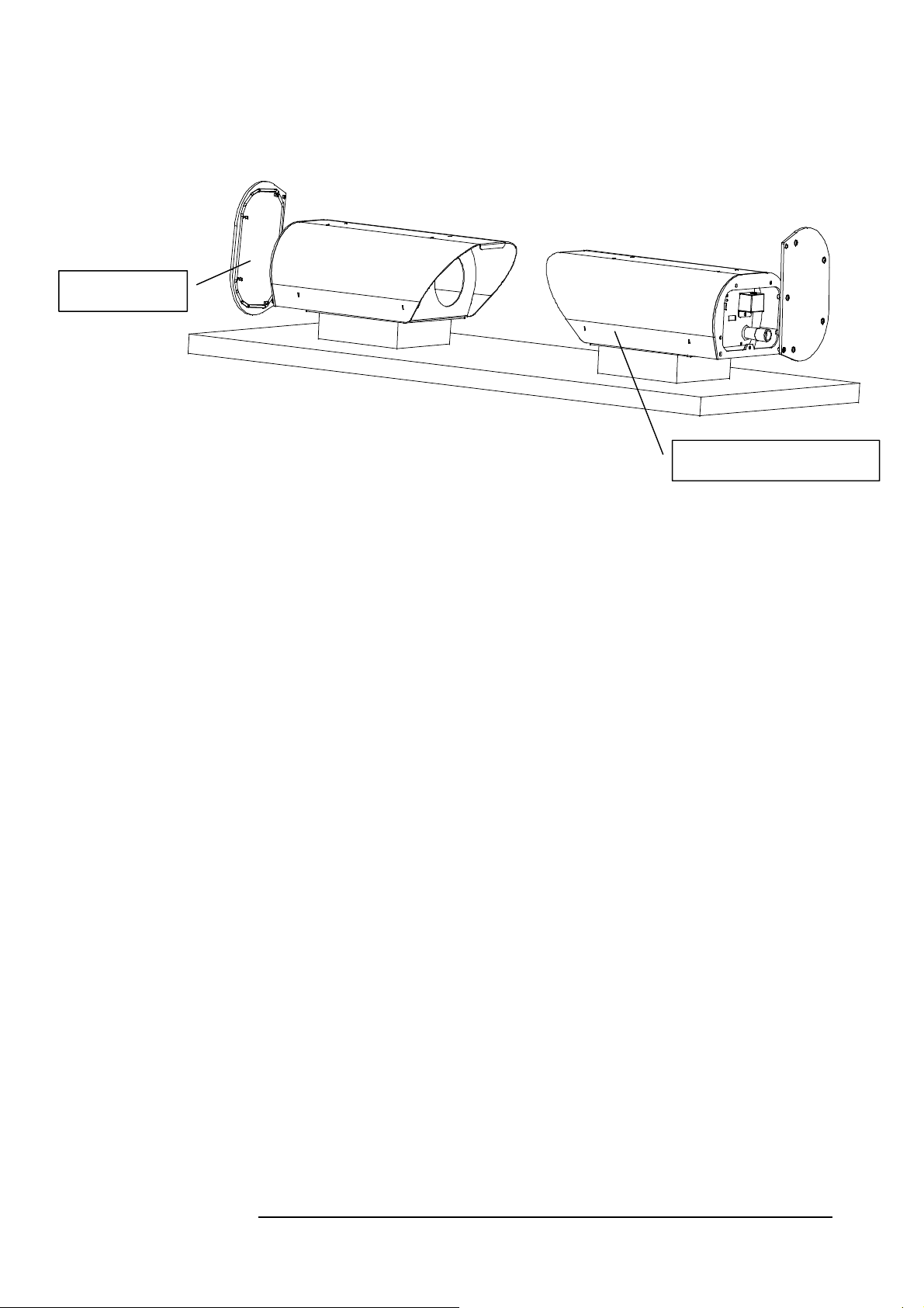
Rear Door fixed
MRV Communications, Inc. – Installation Manual
The second way is to put under the TereScope some object (minimum height 3 cm), which will make the TereScope stand straight without leaning on the
door. The foam, used for TereScopes packaging can be used for this purpose.
Elevation on high object
Figure E.5: Bench test with TereScopes elevated.
65
Page 77

Page 78

MRV Communications, Inc. – Installation Manual
APPENDIX F
Effect of Wind on Terescope Devices
Introduction
The outdoor environment in which our devices are normally placed exposes the
link to wind pressures that may affect the accuracy of the link’s alignment.
Several factors play a role in the determination of the extent to which the directionality of
a TS device may be affected by the wind:
Wind speed
Wind direction
Surface area of device perpendicular to wind
Mechanical stability of aiming head – device system.
For example, the mechanical stability is greatest along the side-side axis of the device.
Although the surface area along the side of the device is greatest, the resultant wind force
– even at very high wind speeds – will barely have an impact on the beam’s direction, due
to the rigid mechanics along the side-side axis.
Wind Limits for TS Devices
All TS devices have been tested in “worst-case” scenario of the above four factors.
The force necessary to deviate beam was measured from different direction.
From here1, the minimum wind speed with maximum effect on beam deviation was
determined.
The following table lists the minimum wind speeds for different TS products that may
cause:
A momentary lapse in the communication.
An extended lapse requiring mechanical repair.
TS Device Momentary Extended
• 10” (E&F models)
• 10” with Windproof-L
Accessory
• 4” (B,C, D models)
• 4” with Windproof-S
• Light (700& 800 series)
• PAL (TS1)
• 8” (Models 2000, 4000
and 5000 series)
110 Km/hr 200 Km/hr
Over 180 Km/hr Over 250 Km/hr
150 Km/hr Over 250 Km/hr
220 Km/hr Over 300 km/hr
150 Km/hr Over 250 Km/hr
180 Km/hr Over 250 Km/hr
200 Km/hr
1
We include here the formula for calculating the effective wind force on a flat surface, given a known wind
speed:
Wind Force = 0.79 x (Wind Speed)
For instance, assuming a wind speed of 27.78 m/s (equal to 100Km/hr) on a surface area of 0.04m2
(400cm2), the force is equal to 24.4 Newtons.
2
x (Area of Surface)
67
Page 79
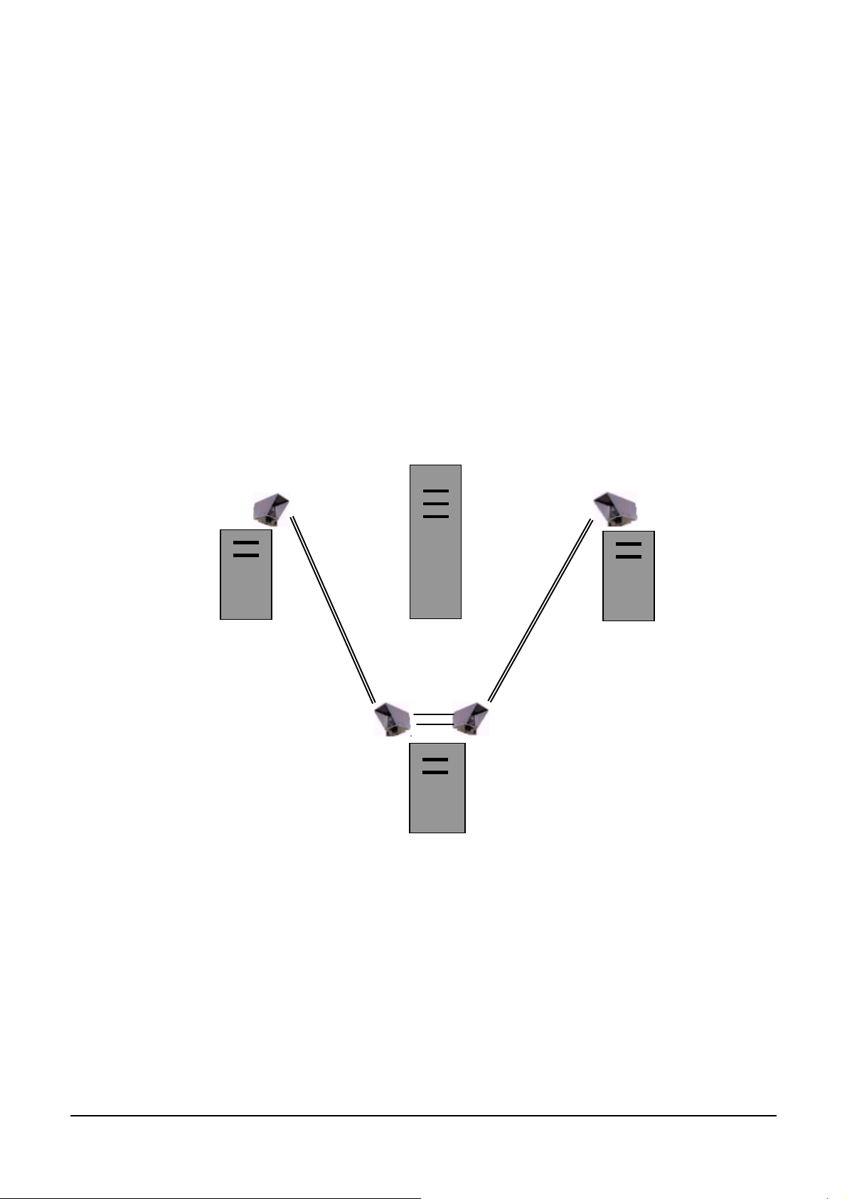
MRV Communications, Inc. – Installation Manual
Appendix G FSO Chaining
What is Chaining?
The Chaining of FSO is required when the two sites are connected by more than one link using at least
one additional building as a mid-point.
When is the Chaining required?
The Chaining of FSO links is required in the following cases:
a) When there is no direct line of sight between the sites;
b) When the distance between the sites is too long;
c) When the distance between the sites is reachable with one link but the customer wants much
more Power Budget for higher reliability.
A
B
C
Fig G.1:
As there is no line of sight from
A to B, we are using C as a
repeater point. On C rooftop we
used “ Direct Chaining
connectivity
68
Page 80
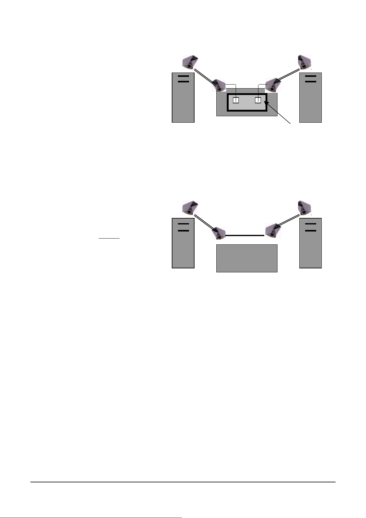
MRV Communications, Inc. – Installation Manual
n
d
T
n
e
Indirect Chaining
Indirect Chaining is required for
connecting FSO units not including
clock recovery circuits. In cases of
indirect connectivity, the connection
between the two FSO units on the
same roof must be done through the
Switch or Router or another means
of connection that is located inside
the building. For example, in Fig. 2, we
use the indoor switch in building C for
the chaining.
A
C
Fig. G.2
Indirect chaining
B
Direct Chaining
Direct Chaining is the capability to
directly connect two FSO units o
the same roof (used as repeaters)
i.e.. direct crossing between Rx an
X of the two units. For example,
in Fig. 3 connection is achieved o
rooftop of building C without th
need to enter the building.
Direct connection is possible for
FSO that include clock recovery
circuits. The clock recovery
regenerates the signal and
A
C
B
enables smooth direct chaining.
Fig. G.3
Direct chaining
Chaining Limits
The number of links that can be chained is limited due to the Jitter parameter. Sensitivity to jitter is different for
every protocol and can vary with different manufacturers. The typical number is 3-4 chained links. If more
chains are required, please consult your MRV representative.
69
Page 81

MRV Communications, Inc. – Installation Manual
FSO products & Chaining
Product series
Chaining No of chained links
TSG (100-1500 Mbps)
Indirect 3-4
TS155-PS (1-155 Mbps)
Direct 3-4
TS100 (Fast-Ethernet)
Direct 3-4
TS34 (Open Protocol, 1-34 Mbps) Indirect 3-4
TS10 (Ethernet)
Direct 3-4
TS Mux (Mux 4E1, 4T1)
Direct No Limits*
TS2 (E1, T1)
Direct No Limits*
*No Limits – it refers to Networking extensions. If the extensions are of TDM type (E1,E3, STM-1, STM-3 ), after
some chains we might face some “jitter” problems. Therefore, in such cases, chaining should be considered on a case by case
basis.
70
Page 82
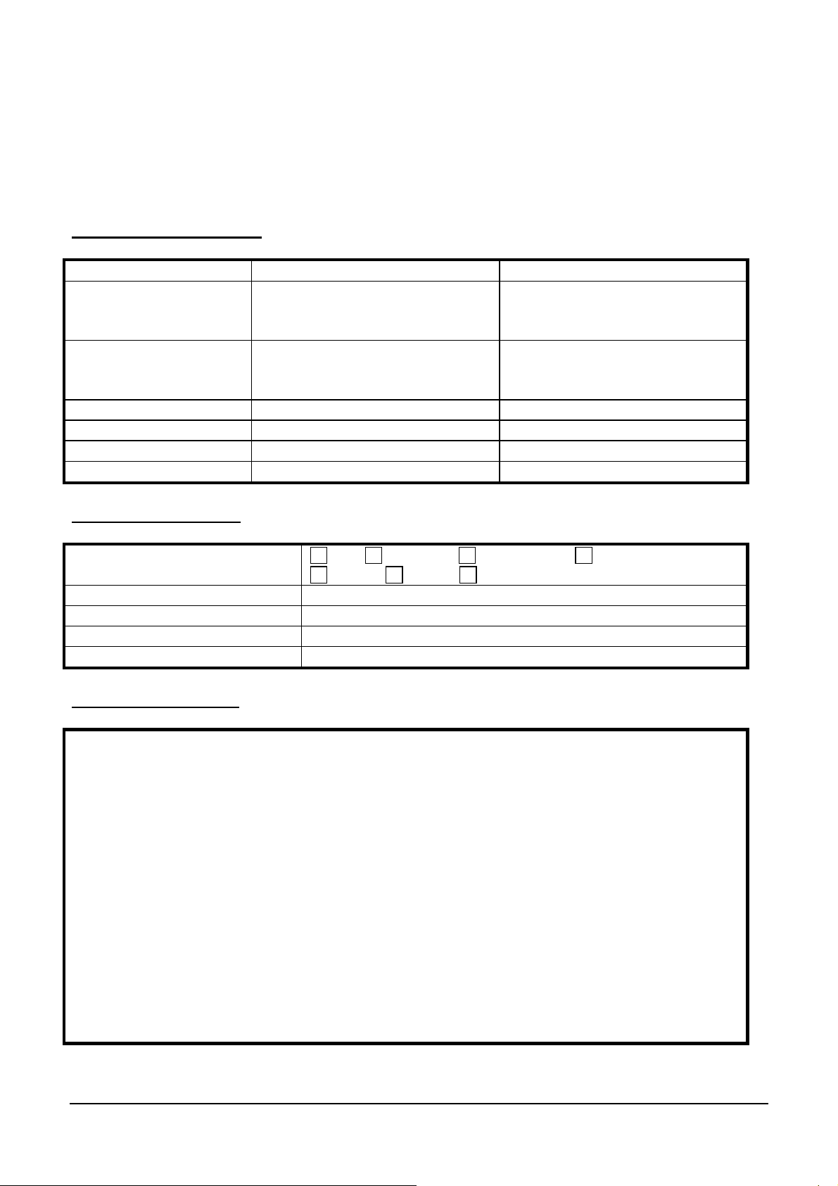
MRV Communications, Inc. – Installation Manual
APPENDIX H Installation Log
D.1. Client / Dealer details
Customer Dealer
Company Name
Address
City
Country
Contact Person
Tel
Fax
e-mail
D.2. Application details
Type of network E1 , Ethernet , Token Ring , Fast Ethernet ,
Product
Evaluated distance by customer
Address of installation (site A)
Address of installation (site B)
D.3. Sketch of the area
FDDI , ATM , Other (Specify)
71
Page 83
MRV Communications, Inc. – Installation Manual
D.4. Site survey
Done by
Customer representative
Distance
Date
Site A Site B
Location
Floor
Orientation (NSEW)
Installation site scheme
Indoor / Outdoor
Plate JMP / Bracket JMB
Window attenuation
On-line UPS
Voltage required (110V / 230V)
Ground earthing
Radio antenna field
Associated interface
Site A Site B
equipment
Manufacturer
Type
Model number
Interface type
72
Page 84
MRV Communications, Inc. – Installation Manual
D.5. Installation
Done by
Customer representative
Date
Site A Site B
System model
Serial number
Location: Same as site survey,
if not provide details
Accessories : Same as site
survey, if not provide details
Digital readout
Telescope calibration :
if cannot , sketch the telescope
view
BER test
BER equipment type
Loopback location
Error type (random, burst)
Brief interruption test
73
Page 85
MRV Communications, Inc. – Installation Manual
D.6. System failure
Visit made by
Customer representative
Date
Site A Site B
Sketch of telescope view
Digital readout
Failure detail
Action items
Visit made by
Customer representative
Date
Site A Site B
Sketch of telescope view
Digital readout
Failure detail
Action items
74
Page 86
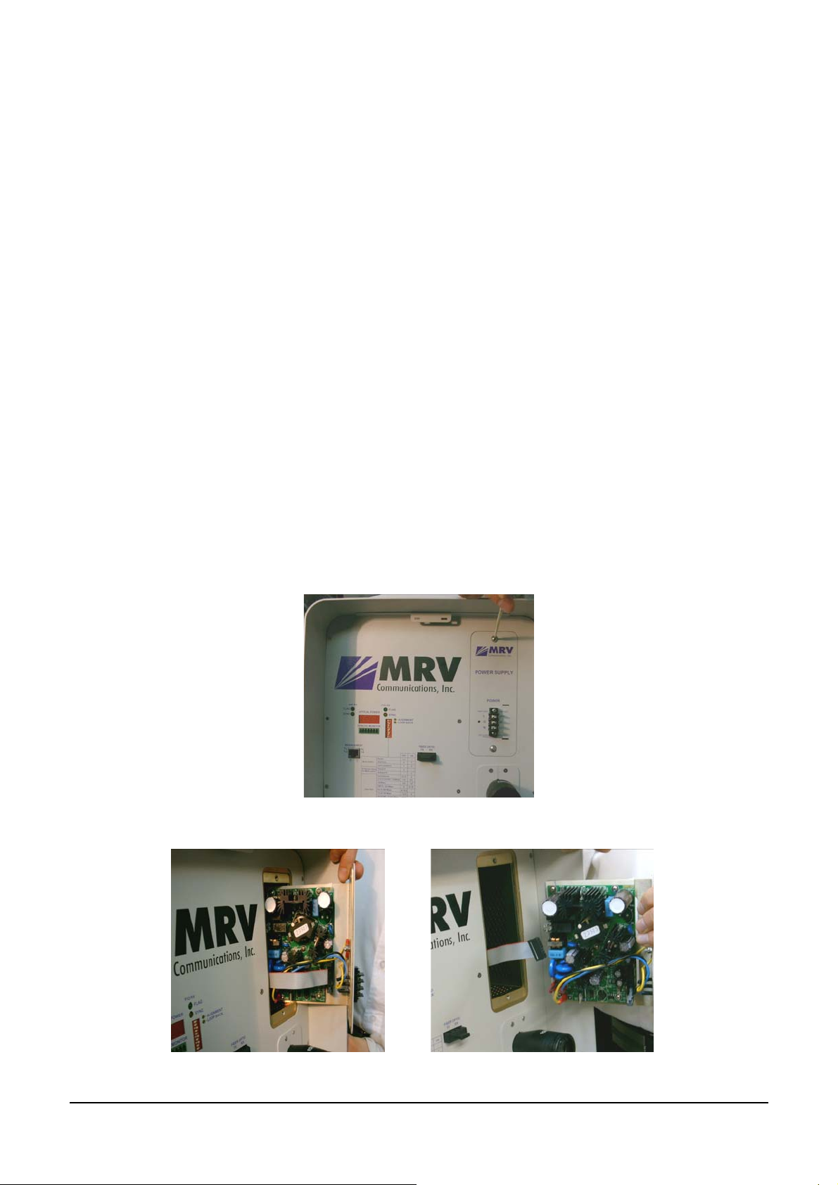
MRV Communications, Inc. – Installation Manual
APPENDIX I
Power Supply Replacement
General
The PS-X000-PR-XX power supply is used in the TS5000 and in TS4000 series. It is pluggable and may be DC
(24 to 60 Vdc, or 35-60Vdc for TS5000 series) or AC (100-240 Vac). The power supply can be simply hot
swapped within seconds without the need for performing any other changes to the TereScope.
Procedure
The procedure for replacing the power supply in the TS5000 is as follows:
1. Turn off the power to the TS5000.
2. Remove the back door by undoing the four (4) allen screws.
3. Remove the power supply cover by undoing the single screw.
4. Disconnect the three (3) wires of the power cable by undoing the three (3) screws.
5. Undo the two ‘N’ screws (shown in Figure I.1) and carefully pull out the power supply as
shown in Figure I.2.
6. Disconnect the flat cable from the power supply as shown in Figure I.3.
7. Connect the flat cable to the new power supply.
8. Fasten the new power supply with the two ‘N’ screws.
9. Connect the three (3) wires of the power cable with the three (3) screws.
10. Fasten the power supply cover with the single screw.
11. Fasten the power supply back door with the four (4) Allen screws.
12. Turn on the power to the TS5000.Power.
Figure I.1: Undoing an ‘N’ Screw
Figure I.2: Pulled out Power Supply Figure I.3: Disconnected Flat Cable
75
Page 87
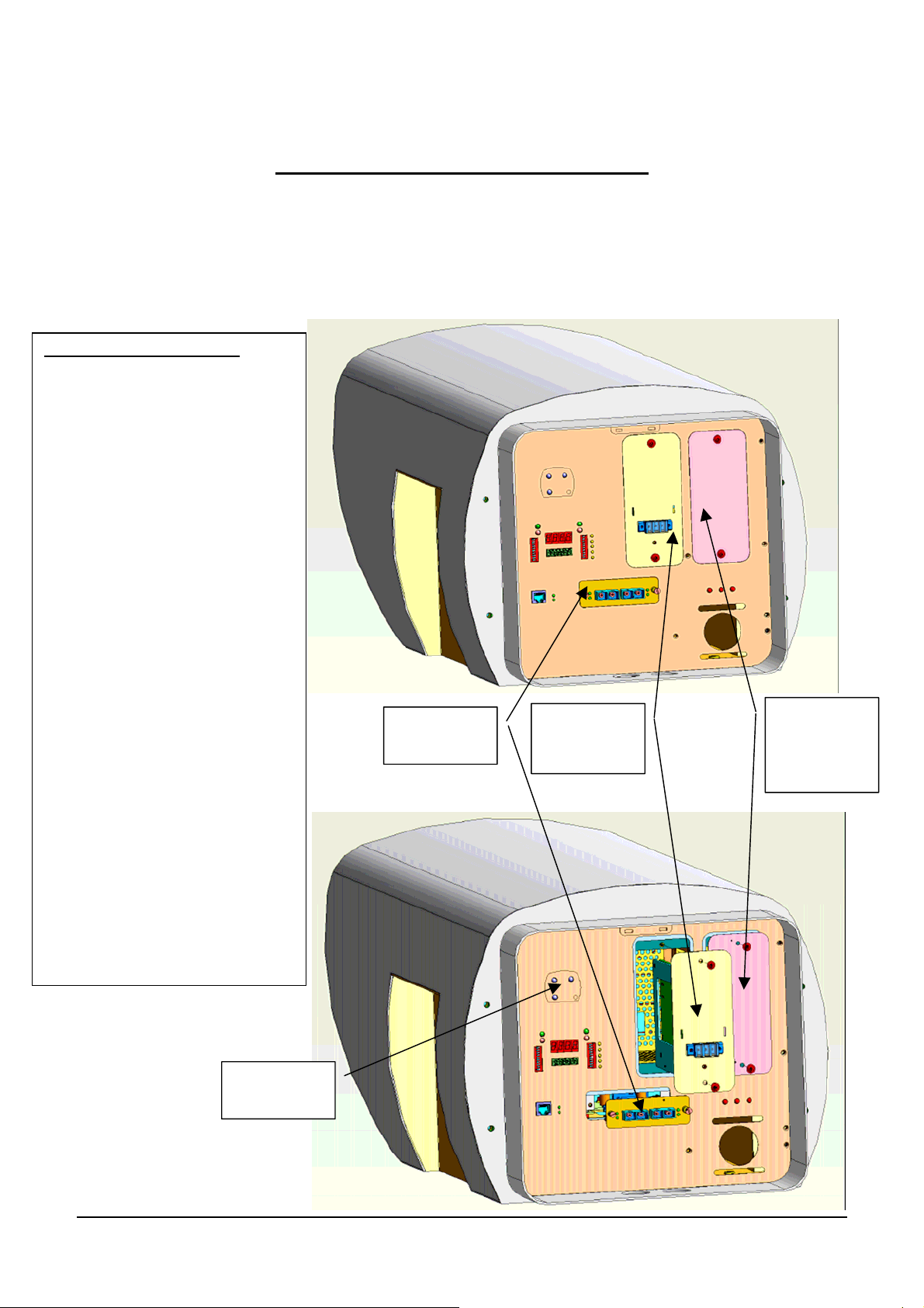
MRV Communications, Inc. – Installation Manual
APPENDIX J
TS5000/155 and TS4000/155 enhancements
Constantly striving for excellence and customer satisfaction, as befits the world leader in the FSO, MRV is presently
enhancing its TS4000/155 (p/n TS4000/XYZ/V**) and the TS5000/155 (TS5000/XYZ/V**) TereScope systems to make
the operation of these devices easier. For example, from now on if a customer does not ordered a Fusion option and
afterwards changed his mind, he will not have to return the TereScope to the factory, he will b e able to quickly and easily
replace the interface by himself. Also, an optional additional power supply can double the MTBF of these products.
The improvements consist of:
1 – Redundant power supply : it is
possible to order an additional power
supply for the TS head. In this case if
the main power supply fails, the
redundant will continue the job without
cutting the link.
2 – The interface is removable: the
distributor or the client can change the
interface without sending the unit to
MRV. (good for changing from MM to
SM or to add the FUSION soltion…)
3 – Laser enable indicators: While it is
a new feature for the TS4000/155,
TS5000/155 always had it - just the
indicators’ location on the back panel
and their size were changed.
4 – SNMP management: a new SNMP
card is integrated, the features are:
a - Two new functions :
• Local Loop back
• Remote Loop Back
b - Active Management (not only
monitoring):
• Local Loop back
• Remote Loop Back
• Reset
• Fusion
• Add Power supplies status
• Software or hardware mode
Removable
Interface
Main
removable
Power supply
Redundant
removable
Power supply
(Optional)
Lasers Enable
indicators
76
 Loading...