

Page 1
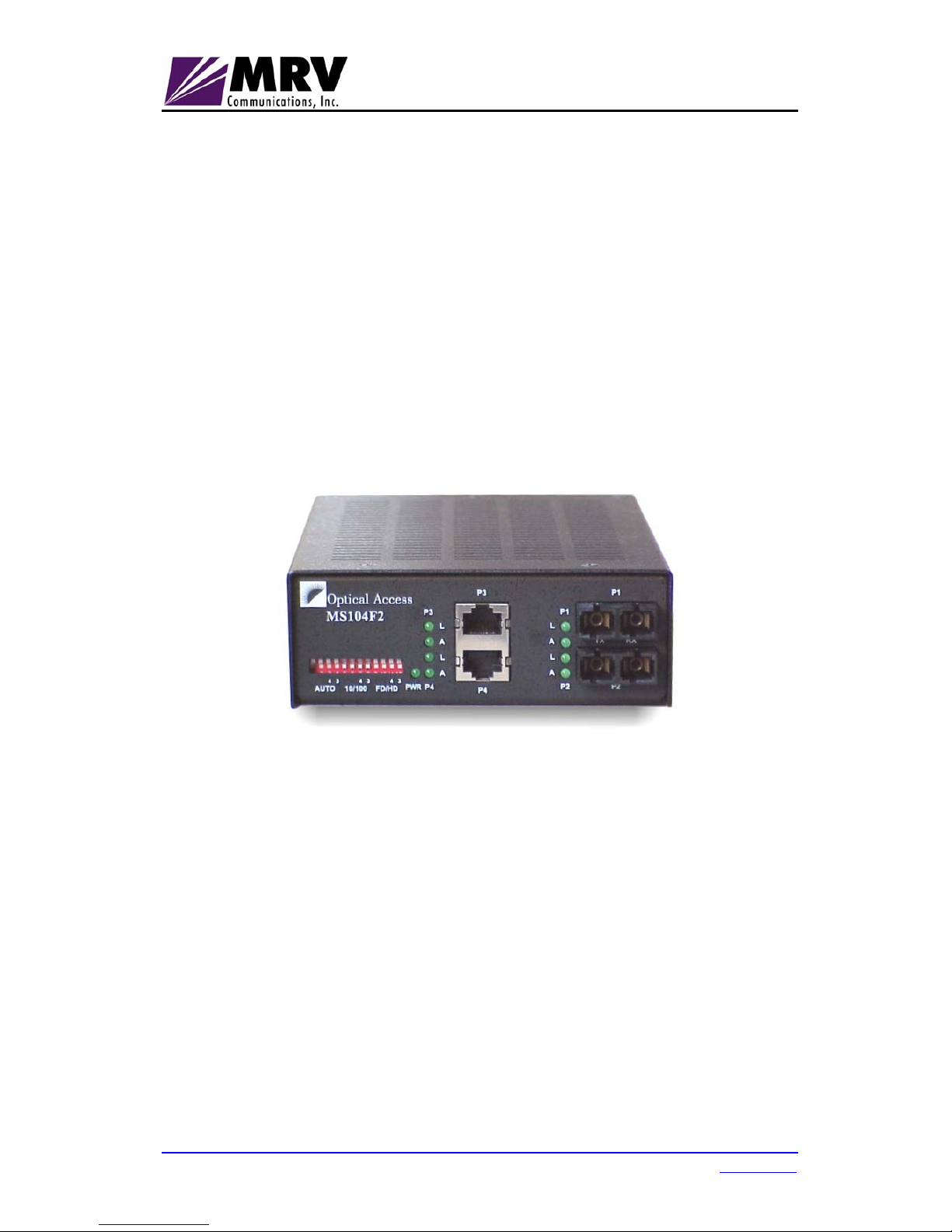
MS 104/5
Ethernet Switches
User Manual
MRV Communications, Inc. URL: http://www.m rv.com
Page 2

MS 104/5
ML46758, Rev. 01
June 2002
Standards Compliance
UL-1950; CSA-22.2 No.950; FCC part 15 Class A; CE - 89/336/EEC, 73/23/EEC.
Disclaimer
MRV reserves the right to modify the equipment at any time and in any way it sees fit in order to improve it.
MRV provides this document without any warranty of any kind, either expressed or implied, including, but
not limited to, the implied warranties of merchantability or fitness for a particular purpose.
Even though much care has been taken in the preparation of this document, omissions and errors may still
exist. Therefore, the customer is advised to exercise due discretion in the use of the contents of this
document since the customer bears sole responsibility.
Trademarks
All trademarks are the property of their respective holders.
Copyright © 2002 by MRV
All rights reserved. No part of this document may be reproduced without the prior permission of MRV.
This document and the information contained herein are proprietary to MRV and are furnished to the
recipient solely for use in operating, maintaining and repairing MRV
equipment. The information within may
not be utilized for any purpose except as stated herein, and may not be disclosed to third parties without
written permission from MRV. MRV
reserves the right to make changes to any technical specifications in
order to improve reliability, function or design.
Document Number:
ML46758
Document Revision:
Rev. 01
Release Date:
June 2002
2
Page 3

MS 104/5
ML46758, Rev. 01
June 2002
Contents
About this Manual............................................................................. 5
Acronyms .......................................................................................... 5
Safety Requirements ........................................................................ 5
Overview............................................................................................6
General............................................................................................................ 6
Models............................................................................................................. 6
Applications.................................................................................................... 6
Features .......................................................................................................... 6
Available ...................................................................................................... 6
Optional........................................................................................................ 7
Layout ............................................................................................................. 8
Front View.................................................................................................... 8
Ports............................................................................................................. 9
DIP Switch ................................................................................................... 9
LED Indicators............................................................................................ 11
Installation and Setup..................................................................... 12
Package Contents ........................................................................................ 12
Procedure ..................................................................................................... 12
Operation.........................................................................................12
Troubleshooting.............................................................................. 13
Product Specification .....................................................................14
Appendix A: Models ......................................................................15
Appendix B: Cleaning Optical Connectors ................................. 16
General.......................................................................................................... 16
Tools and Equipment................................................................................... 16
Procedure ..................................................................................................... 16
3
Page 4

MS 104/5
ML46758, Rev. 01
June 2002
Figures
Figure 1: Applications of the MS 104 and MS 105 .............................................. 6
Figure 2: MS 104F2............................................................................................. 8
Figure 3: MS 105F............................................................................................... 8
Figure 4: MS 105FR............................................................................................ 8
Figure 5: Interconnection of MS 104/5 and another Device .............................. 12
Tables
Table 1: DIP Switch Setting................................................................................. 9
Table 2: Front Panel LEDs ................................................................................ 11
Table 3: Startup and Operation Troubleshooting .............................................. 13
4
Page 5
MS 104/5
ML46758, Rev. 01
June 2002
About this Manual
This manual is intended for the user who wishes to install, operate, and
troubleshoot the MS 104/5 Ethernet switches.
Acronyms
CRC
Cyclic Redundancy Check
DIP
Dual In-line Package
FDB
Filtering/Forwarding DataBase
LED
Light Emiting Diode
MAC
Media Access Control
MDI
Media-Dependent Interface
MM
MultiMode
SM
SingleMode
ToS
Type of Service
Safety Requirements
Caution!
To reduce risk of electrical shock and fire and to maintain proper operation,
ensure that the safety requirements stated hereunder are met!
Before installing the MS 104/5, ensure the following:
1. All power to the MS 104/5 is cut off.
2. By visual inspection, no part is damaged.
Do not connect or disconnect the electrical cable and/or power cord during
lightning strikes or thunderstorms.
5
Page 6
MS 104/5
ML46758, Rev. 01
June 2002
Overview
General
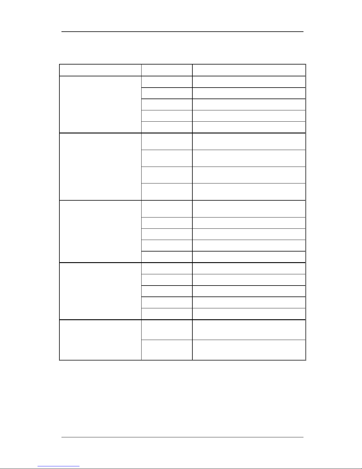
MS 104/5 are members of a families of mixed media Ethernet switches.
Models
The models in each family are described in
Appendix A: Models
.
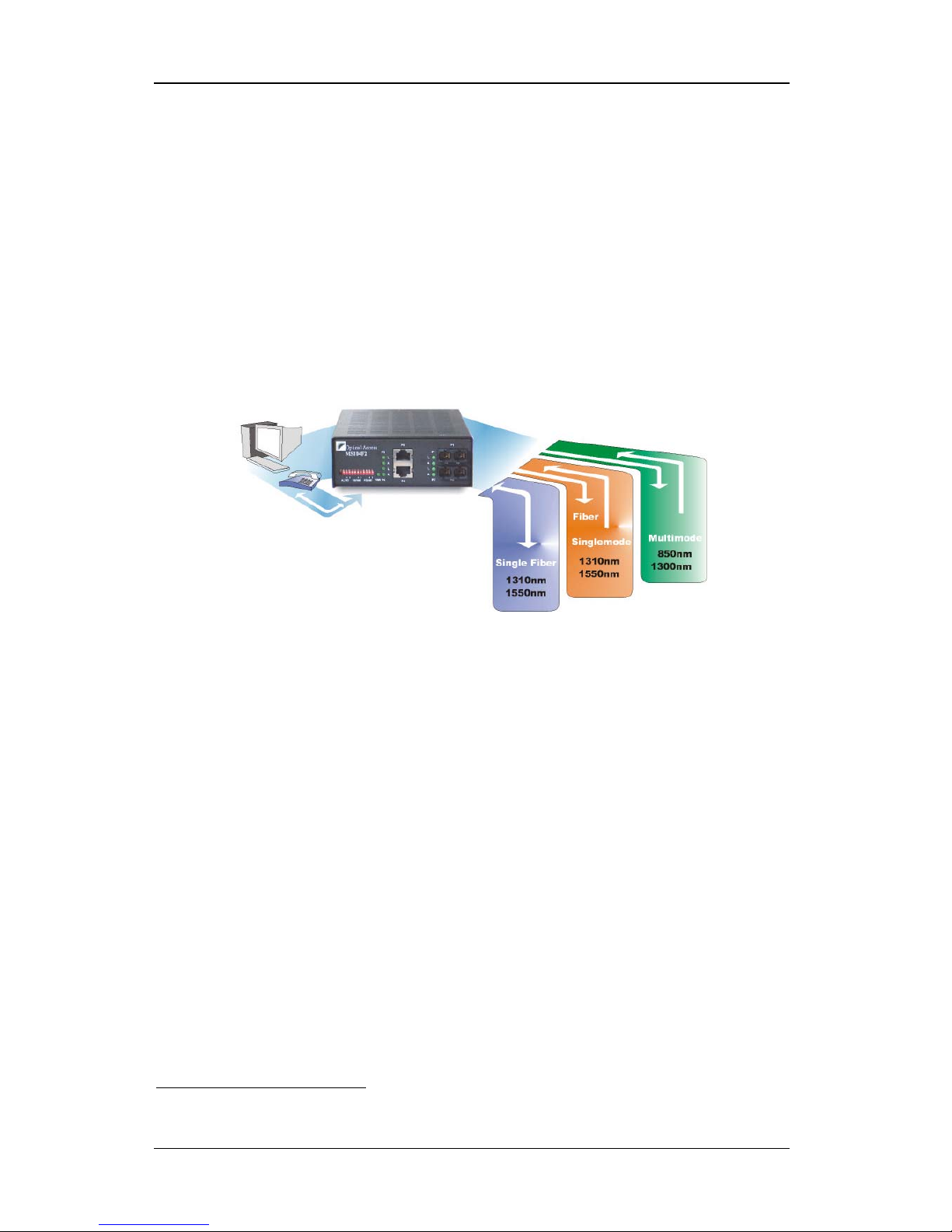
Applications
Figure 1: Applications of the MS 104 and MS 105
Features
Available
• Domain-per-Port
– Partitioning of networks connected to ports into
separate collision domains.
• Store-&-Forward
– Performance of packet CRC and legal size check
prior to resolving whether it is a runt, jabber, or CRC error packet and
discarding it if it is so.
• Auto-Negotation
(or Auto-Sensing) – Automatic self reconfiguration
capability of the 10BASE-T/100BASE-TX switching ports to operate
optimally, i.e., at 100 Mbps speed (rather than at 10 Mbps) and in
full-duplex mode (rather than in half-duplex mode) if the co-port
1
too has
auto-negotation capability. Auto-negotation can be activated or deactivated for each port individually.
• Wire-Speed Operation
– Transmission and reception of packets by all
ports at full link speed with zero packet loss.
1
Co-port is another port which receives from or forwards to an MS 104/5 port.
6
Page 7

MS 104/5
ML46758, Rev. 01
June 2002
• Auto-Configuration
– Each 10/100Base-TX port can be connected to an
Ethernet MDI or MDI-X port with a straight or cross-over cable since the
port automatically configures itself to suit the cable type and co-port
interface.
• Filtering/Forwarding Database (FDB)
– Current map of connected
stations (identified by their MAC address) to ports. The map is dynamically
updated and can maintain as many as 1024 MAC addresses.
• Auto-Learning
– Automatic addition of MAC addresses of new stations to
FDB.
• Auto-Aging
– Clearance of MAC address of station in MS 104/5 FDB if
not accessed for 5 minutes.
• VLAN Support
– Switching of packets of length up to 1536 bytes.
• Broadcast Storms Prevention
– Prevention of broadcast storms
resulting from streaming or over-jabbering stations.
• Fiberoptic Cabling
– Connectivity of single-fiber singlemode cables and
dual fiber singlemode or multimode cables.
• VBC
– Virtual Broadcasting Restriction. Port P1 can send and receive
broadcast and unicast packets to/from the other ports (P2, P3, etc.).
However, the other ports (P2, P3, etc.) cannot send and receive broadcast
packets to each other; they can only send and receive unicast packets to
each other.
Optional
• Packet Prioritization
– Assignment of
high
or
low
processing priority to a
packet on the basis of Port, VLAN, or ToS.
• Flow Control
– Forcing of the transmitting station to temporarily back off
when the global memory of the MS 104/5 becomes saturated. This feature
prevents packet loss. It is applicable to ports that operate in
full
-duplex
mode. It can be activated for each port individually.
• Backpressure
– Forcing of transmitting station to temporarily back off
when the global memory of the MS 104/5 becomes saturated. This feature
prevents packet loss. It is applicable to ports that operate in
half
-duplex
mode. It can be activated for each port individually.
• No Aging
– Prevention of clearance of MAC addresses of stations in
MS 104/5 FDB.
• VBC
– Virtual Broadcasting Restriction. Each port can be enabled or
disabled to send/receive broadcast packets from each of the other ports
individually. However, unicast packets can be sent between
any
two ports.
• Port Isolation
– Each port can be isolated
2
from or grouped3 with each of
the other ports individually.
For example, port P1 can be grouped with all the other ports while the
other ports are isolated from each other.
2
disabled to send/receive broadcast and unicast packets.
3
enabled to send/receive broadcast and unicast packets.
7
Page 8
MS 104/5
ML46758, Rev. 01
June 2002
As another example, ports P1 and P3 can be put in one group, ports P2
and P4 in another.
Layout
Front View
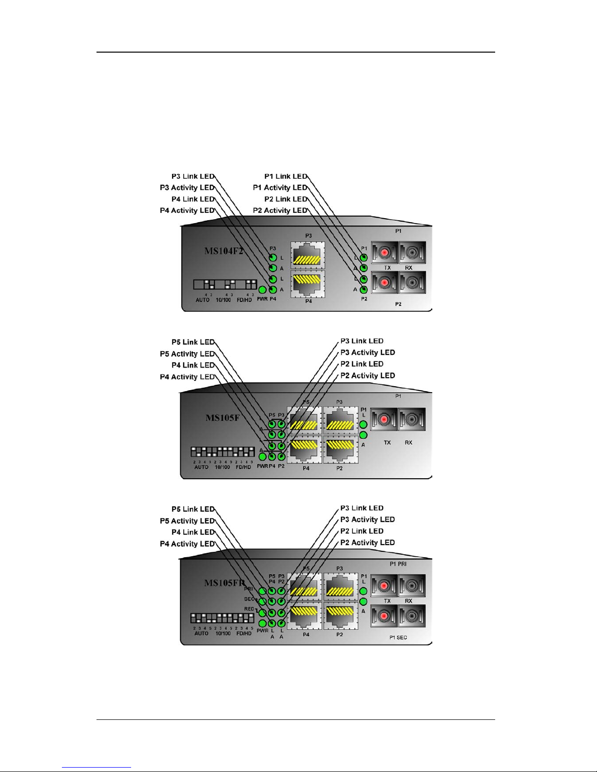
Following are the front views of the MS 104F2, MS 105F, and MS 105FR.
Figure 2: MS 104F2
Figure 3: MS 105F
Figure 4: MS 105FR
8
Page 9
MS 104/5
ML46758, Rev. 01
June 2002
Ports
Power Port
3-prong receptacle for 110V/60Hz or 220V/50Hz line (mains) power input.
100Base-FX Ports
One or two 100Base-FX ports. Each port operates at 100 Mbps, is fitted with a
fiberoptic SC or MT-RJ connector, transmits and receives on 1310 nm or 1550
nm carrier wavelength, and can be connected with a single-fiber singlemode
cable or dual-fiber singlemode cable or dual-fiber multimode cable. The power
budget available depends on the model as described in Appendix A: Models.
10/100Base-TX Ports
Two or four 10/100Base-TX ports. Each port has full auto-negotiation capability,
is fitted with an RJ45 UTP connector, and can be connected with a Category 5
cable up to 100 meters long. To use longer cables, consult your representative.
DIP Switch
12-toggle DIP switch for configuring the operation mode of 10/100Base-TX ports
individually. The toggles are divided into three groups marked
AUTO, 10/100
,
and
FD/HD. AUTO
designates auto-negotiation,
10/100
designates 10/100 Mbps
data rate,
FD/HD
designates full-duplex/half-duplex. Each toggle marked with a
number (e.g., 2, 3, 4 or 5) is
functional
. The number designates the associated
port. Unmarked toggles are not functional and so their position may be ignored.
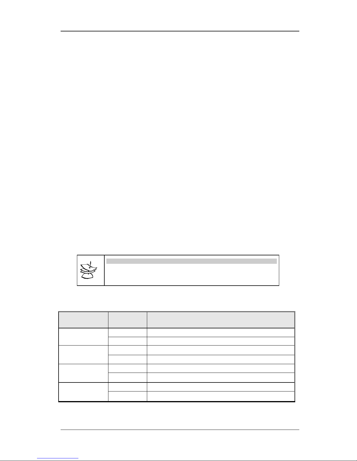
Table 1 specifies each DIP switch toggle, its two positions, and the function of
each position.
Note
To enable a
10/100
or
FD/HD
toggle to function, the
AUTO
toggle marked
with the same number must be set to the
DOWN position, i.e.,
auto-negotiation must be disabled!
Table 1: DIP Switch Setting
DIP Switch
Toggle
Toggle
Position
Function
UP Set Port 2 to operate in auto-negotiation mode.
AUTO 2
DOWN Set Port 2 not to operate in auto-negotiation mode.
UP Set Port 3 to operate in auto-negotiation mode.
AUTO 3
DOWN Set Port 3 not to operate in auto-negotiation mode.
UP Set Port 4 to operate in auto-negotiation mode.
AUTO 4
DOWN Set Port 4 not to operate in auto-negotiation mode.
UP Set Port 5 to operate in auto-negotiation mode.
AUTO 5
DOWN Set Port 5 not to operate in auto-negotiation mode.
9
Page 10

MS 104/5
ML46758, Rev. 01
June 2002
Table 1: DIP Switch Setting (Continued)
UP Set Port 2 to operate at 10 Mbps.
(Effective only if Auto-negotiation DIP switch toggle 3
position is down, i.e., if auto-negotiation is disabled.)
10/100 2
DOWN Set Port 2 to operate at 100 Mbps.
(Effective only if Auto-negotiation DIP switch toggle 3
position is down, i.e., if auto-negotiation is disabled.)
UP
Set Port 3 to operate at 10 Mbps.
(Effective only if Auto-negotiation DIP switch toggle 4
position is down, i.e., if auto-negotiation is disabled.)
10/100 3
DOWN
Set Port 3 to operate at 100 Mbps.
(Effective only if Auto-negotiation DIP switch toggle 4
position is down, i.e., if auto-negotiation is disabled.)
UP Set Port 4 to operate at 10 Mbps.
(Effective only if Auto-negotiation DIP switch toggle 3
position is down, i.e., if auto-negotiation is disabled.)
10/100 4
DOWN Set Port 4 to operate at 100 Mbps.
(Effective only if Auto-negotiation DIP switch toggle 3
position is down, i.e., if auto-negotiation is disabled.)
UP
Set Port 5 to operate at 10 Mbps.
(Effective only if Auto-negotiation DIP switch toggle 4
position is down, i.e., if auto-negotiation is disabled.)
10/100 5
DOWN
Set Port 5 to operate at 100 Mbps.
(Effective only if Auto-negotiation DIP switch toggle 4
position is down, i.e., if auto-negotiation is disabled.)
UP
Set Port 2 to operate in Half-Duplex mode.
(Effective only if Auto-negotiation DIP switch toggle 3
position is down, i.e., if auto-negotiation is disabled.)
FD/HD 2
DOWN
Set Port 2 to operate in Full-Duplex mode.
(Effective only if Auto-negotiation DIP switch toggle 3
position is down, i.e., if auto-negotiation is disabled.)
UP
Set Port 3 to operate in Half-Duplex mode.
(Effective only if Auto-negotiation DIP switch toggle 3
position is down, i.e., if auto-negotiation is disabled.)
FD/HD 3
DOWN
Set Port 3 to operate in Full-Duplex mode.
(Effective only if Auto-negotiation DIP switch toggle 3
position is down, i.e., if auto-negotiation is disabled.)
UP
Set Port 4 to operate in Half-Duplex mode.
(Effective only if Auto-negotiation DIP switch toggle 3
position is down, i.e., if auto-negotiation is disabled.)
FD/HD 4
DOWN
Set Port 4 to operate in Full-Duplex mode.
(Effective only if Auto-negotiation DIP switch toggle 3
position is down, i.e., if auto-negotiation is disabled.)
UP
Set Port 5 to operate in Half-Duplex mode.
(Effective only if Auto-negotiation DIP switch toggle 3
position is down, i.e., if auto-negotiation is disabled.)
FD/HD 5
DOWN
Set Port 5 to operate in Full-Duplex mode.
(Effective only if Auto-negotiation DIP switch toggle 3
position is down, i.e., if auto-negotiation is disabled.)
10
Page 11

MS 104/5
ML46758, Rev. 01
June 2002
LED Indicators
The LEDs are described in Table 2, below.
Table 2: Front Panel LEDs
LED Status Significance
ON MS 104/5 receiving power.
PWR
OFF MS 104/5 not receiving power.
ON Port P 1 link OK.
P1 L
OFF Port P 1 link absent or faulty.
ON Port P 1 activity4 present.
P1 A
OFF Port P 1 activity absent.
ON Port P 2 link OK.
P2 L
OFF Port P 2 link absent or faulty.
ON Port P 2 activity present.
P2 A
OFF Port P 2 activity absent.
ON Port P 3 link OK.
P3 L
OFF Port P 3 link absent or faulty.
ON Port P 3 activity present.
P3 A
OFF Port P 3 activity absent.
ON Port P 4 link OK.
P4 L
OFF Port P 4 link absent or faulty.
ON Port P 4 activity present.
P4 A
OFF Port P 4 activity absent.
ON Port P 5 link OK.
P5 L
OFF Port P 5 link absent or faulty.
ON Port P 5 activity present.
P5 A
OFF Port P 5 activity absent.
ON
Ports P 1 PRI and P 1 SEC set to operate in mutual
redundancy mode.
RED
OFF
Port P 1 PRI set to operate as a regular 100Base-FX
port while port P 1 SEC is disabled.
ON Port PRI OK and receiving.
PRI
OFF Port PRI not OK or not receiving.
ON Port SEC OK and receiving.
SEC
OFF Port SEC not OK or not receiving.
4
transmission/reception
11
Page 12
MS 104/5
ML46758, Rev. 01
June 2002
Installation and Setup
Package Contents
•
MS 104/5
•
Power Cord
•
CD containing User Manual
Procedure
Install the MS 104/5 as follows:
1. Place the MS 104/5 on a flat stable surface (e.g., desk top).
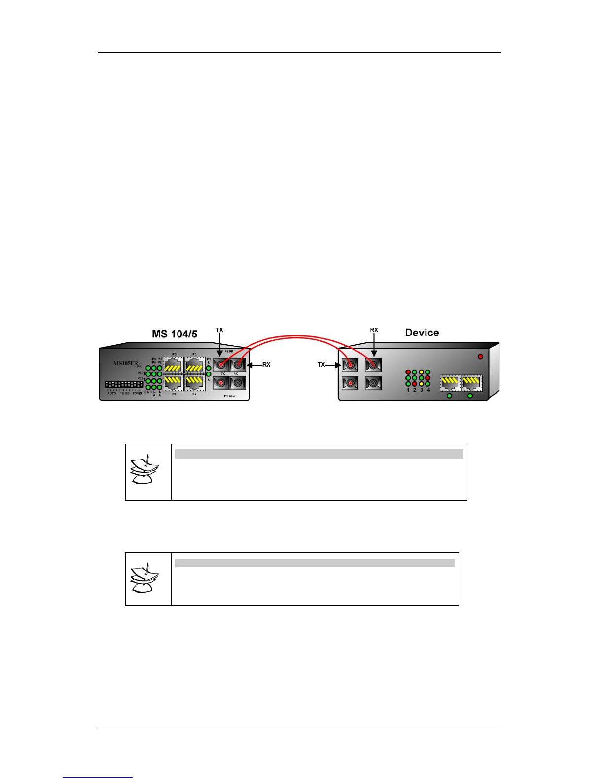
2. Connect the MS 104/5 fiberoptic data ports
TX
and
RX
to the device(s),
ensuring that for each fiber, one end is connected to an RX port while the
other end is connected to a TX port as shown in Figure 5.
3. Interconnect the MS 104/5 electrical data ports and other devices.
Figure 5: Interconnection of MS 104/5 and another Device
4. With the aid of Table 1, set the DIP switch (on the front panel).
Note
If the device port (to which the MS 104/5 electrical data port is
connected) does not have auto-negotiation capability, the MS 104/5
port operates in half-duplex mode and at the same speed of the device port.
5. Connect one end of the power cord to the MS 104/5 power port.
6. Connect the other end of the power cord to the ac line power (mains) to
power on the MS 104/5.
Note
If the DIP switch setting is changed while the MS 104/5 is powered on,
disconnect then reconnect the power cord to enable the MS 104/5 to
operate according to the new setting.
Operation
The MS 104/5 becomes fully operational within a few seconds after being
powered on.
Its operation can be monitored by interpreting the status of its LEDs with the aid
of Table 2. If there is a problem, use the chapter Troubleshooting to resolve it.
12
Page 13

MS 104/5
ML46758, Rev. 01
June 2002
Troubleshooting
The troubleshooting procedure is given in
Table 3
. Read the entries in the
column
Problem
until you reach the problem that applies to the MS 104/5. Then
perform the corrective action(s) appearing in the same row. If the problem
persists, note the status of all the LEDs and consult your
MRV
representative.
Table 3: Startup and Operation Troubleshooting
No Problem Probable Cause Corrective Action
1 PWR
LED off
No line (mains) power. 1. Check power cord
connection.
2. Check line (mains) power
wall outlet.
3. Check power cord.
2
Fiberoptic port L LED off
No link on fiberoptic cable. 1. Check fiberoptic cable
connections.
2. Check device at other end
of fiberoptic cable.
3. Check fiberoptic cable.
4. Clean connectors as
described in Appendix B:
Cleaning Optical
Connectors.
3
Copper port L LED off
Bad STP/UTP cable connection. 1. Check electrical cable
connections.
2. Check device at other end
of electrical cable.
3. Check electrical cable.
4
Fiberoptic port
performance lower than
expected
Duplexity mismatch. Ensure that the port and co-port
are set to the same duplexity.
5
Copper port performance
lower than expected
Device connected to this port is
not auto-negotiating and is
operating in full-duplex mode.
Set DIP switch AUTO toggle
and 10/100 toggle associated
with the MS 104/5 port are set
to down position.
6
PRI LED off. Link to P1 SEC port active, i.e.,
SEC LED on.
1. Check fiberoptic cable
connections to the P1 PRI
ports (TX, RX).
2. Check fiberoptic cable.
3. Clean connectors as
described in Appendix B:
Cleaning Optical
Connectors.
13
Page 14

MS 104/5
ML46758, Rev. 01
June 2002
Product Specification
Switching
Domain-per-Port, Store-&-Forward, Auto-Negotation, Wire-Speed Operation,
Auto-Configuration, Filtering Database (FDB), Auto-Learning, Auto-Aging,
VLAN Support, Broadcast Storms Prevention, 1024 MAC addresses
supported, Single-Fiber Cable Support
Wavelength
(nm)
1310 nm, 1550 nm
(model dependent – see Appendix A: Models)
Fiber Type
MM 62.5/125 µm, SM 9/125 µm
(model dependent – see Appendix A: Models)
Fiber Connector
SC, MT-RJ
(model dependent – see Appendix A: Models)
Optical Data Port Power
Budget
9 dB to 24 dB
(model dependent – see Appendix A: Models)
Electrical Data Port
Supported Speeds
Connector Type
Connector Pinout:
MDI-X
MDI
10 and 100 Mbps
RJ45 8-pin shielded female
1ÆTx+; 2ÆTx-; 3ÆRx+; 6ÆRx-
1ÆRx+; 2ÆRx-; 3ÆTx+; 6ÆTx-
Transmission Rate
10/100 Mbps
Maximum Frame size
1536 bytes
Power (ac)
Line (Mains)
Consumption
90V-240V, 60/50Hz
Less than 12 W
Temperature
Operating
Storage
0 to 40
O
C (32 to 104 OF)
-40 to 70
O
C (-40 to 158 OF)
Humidity
(non-
condensing)
Less than 85%
Dimension
120 mm x 180 mm x 45 mm (4
2
/3 in x 7 in x 13/4 in)
Weight
500 g (1 lb, 1
2
/3 oz)
Compliance
Safety
Network
UL-1950; CSA-22.2 No.950; FCC part 15 Class A; CE - 89/336/EEC,
73/23/EEC
IEEE 802.3, IEEE 802.3u,
F = Fast, I = Internal Power, M = Multimode, S = Singlemode
14
Page 15
MS 104/5
ML46758, Rev. 01
June 2002
Appendix A: Models
Family Models
Description
MS105F/M
4 10/100BaseTX ports, one 100BaseFX uplink port
(MM, 1310nm, 0-2km, DSC)
MS105F/MT/M
4 10/100BaseTX ports & one 100BaseFX uplink
port (MM, 1310nm, 0-2km, MT-RJ)
MS105F/S1
4 10/100BaseTX ports & one 100BaseFX port
switch (SM, 1310nm, 0-40km, DSC)
MS105F/S2
4 10/100BaseTX ports & one 100BaseFX port
switch (SM, 1310nm, 20-60km, DSC)
5 Ports, Dual-Fiber
MS105F/S3
4 10/100BaseTX ports & one 100BaseFX port
switch (SM, 1550nm, 20-100km, DSC)
MS105FSF13/S1
4 10/100BaseTX ports & one 100BaseFX single
fiber port switch (SM; 1310nm transmitter;
0-30km; SC)
MS105FSF15/S1
4 10/100BaseTX ports & one 100BaseFX single
fiber port switch (SM; 1550nm transmitter;
0-30km; SC)
MS105FSF13/S2
4 10/100BaseTX ports & one 100BaseFX single
fiber port switch (SM; 1310nm transmitter;
0-50km; SC)
5 Ports, Single-Fiber
MS105FSF15/S2
4 10/100BaseTX ports & one 100BaseFX single
fiber port switch (SM; 1310nm transmitter;
0-50km; SC)
MS105FR/M
4 10/100BaseTX ports & one redundant
100BaseFX port switch (MM, 1310nm, 0-2km,
DSC)
MS105FR/MT/M
4 10/100BaseTX ports & one redundant
100BaseFX port (MM, 1310nm, 0-2km, MT-RJ)
MS105FR/S1
4 10/100BaseTX ports & one redundant
100BaseFX port (SM, 1310nm, 0-40km, DSC)
MS105FR/S2
4 10/100BaseTX ports & one redundant
100BaseFX port (SM, 1310nm, 20-60km, DSC)
5 Ports, Fiber Redundancy
MS105FR/S3
4 10/100BaseTX ports & one redundant
100BaseFX port (SM, 1310nm, 20-100km, DSC)
MS104F2/M
2 10/100BaseTX ports & 2 100BaseFX ports
switch (MM, 1310nm, 0-2km, DSC)
MS104F2/MT/M
2 10/100BaseTX ports & 2 100BaseFX ports (MM,
1310nm, 0-2km, MT-RJ)
MS104F2/S1
2 10/100BaseTX ports & 2 100BaseFX ports (SM,
1310nm, 0-40km, DSC)
MS104F2/S2
2 10/100BaseTX ports & 2 100BaseFX ports (SM,
1310nm, 20-60km, DSC)
4 Ports, Dual-Fiber
MS104F2/S3
2 10/100BaseTX ports & 2 100BaseFX ports (SM,
1550nm, transmitter; 50-100km, DSC)
MS104F/SF/S1
4 10/100BaseTX ports & one 100BaseFX single
fiber port switch (SM, 1310 nm transmitter;
0-30km; SC)
4 Ports, Single-Fiber
MS104F/SF/S2
4 10/100BaseTX ports & one 100BaseFX single
fiber port switch (SM; 1310nm transmitter;
0-50km; SC)
F = Fast Ethernet, R = Port Redundancy, S = Singlemode, M = Multimode, SF = Single Fiber, DSC = Dual
SC connector, MT = MT-RJ connector.
15
Page 16

MS 104/5
ML46758, Rev. 01
June 2002
Appendix B: Cleaning Optical
Connectors
General
Intrusions (e.g., dust, grease, etc.) at the interface of two optical fibers, such as
at a pair of coupled connectors, attenuate the signal through the fiber.
Consequently, optical connectors must be cleaned before they are coupled with
other connectors.
Tools and Equipment
Following are tools and equipment required for cleaning connectors.
• Dust caps
Caps for protecting the connector from intrusions. A cap is usually made
from flexible plastic. When placing a cap over a connector, avoid pressing
it against the fiber ferula surface in the connector so as to prevent
contamination.
• Isopropyl alcohol
Solvent for contaminants.
• Tissues
Soft multi-layered fabric made from non-recycled cellulose.
Procedure
The procedure for cleaning connectors is as follows:
1. If no stains are present, using a new clean dry tissue, gently rub, in small
circular motions, the exposed fiber surface and surrounding area in the
connector to remove dust.
2. If stains are present,
A. Moisten a new clean dry tissue with isopropyl alcohol and gently
rub, in small circular motions, the exposed fiber surface and
surrounding area in the connector to remove the stains.
B. Using a new clean
dry
tissue, gently rub, in small circular motions,
the exposed fiber surface and surrounding area in the connector to
remove the dissolved stains and excess isopropyl alcohol.
C. If a connector is
not
to be coupled with another immediately, cover
it with a dust cap.
16
 Loading...