

Page 1
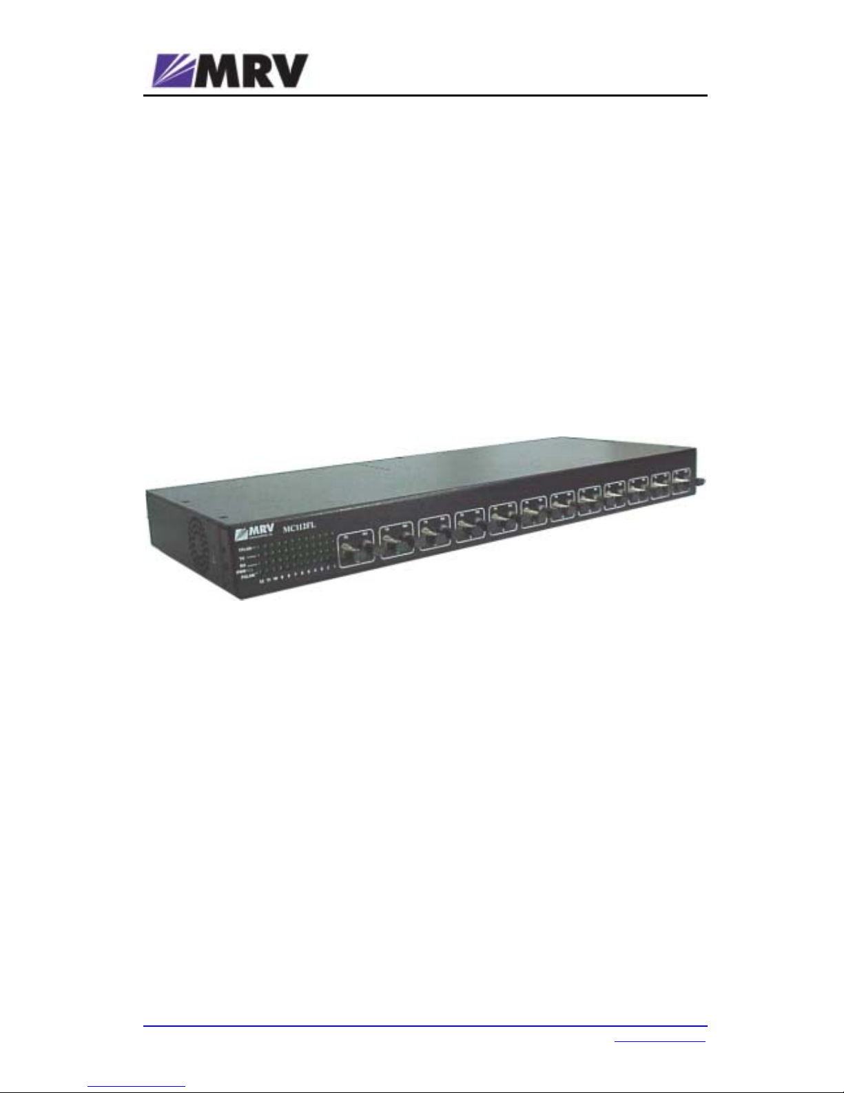
MC112FL
Ethernet 12-Port Media Converter
User Manual
MRV Communications, Inc. URL: http://www.mrv.com
Page 2

MC112FL User Manual ML47766, Rev. 02 July 2007
Standards Compliance
This equipment is designed to comply with UL 1950; CSA 22.2 No 950; FCC Part 15 Class B;
CE-89/336/EEC, 73/23/EEC.
FCC Notice
WARNING: This equipment is designed to comply with the limits for a Class B digital device,
pursuant to Part 15 of the FCC Rules. These limits are designed to provide reasonable protection
against harmful interference when the equipment is operated in a commercial environment. This
equipment generates, uses, and can radiate radio frequency energy and, if not installed and used
in accordance with the manual, may cause harmful interference to radio communications.
Operation of this equipment in a residential area is likely to cause harmful interference in which
case the user will be required to correct for the interference at the user’s own expense.
The user is cautioned that changes and modifications made to the equipment without approval of
the manufacturer could void the user’s authority to operate this equipment.
It is suggested that the user use only shielded and grounded cables when appropriate to ensure
compliance with FCC Rules.
Disclaimer
MRV
®
reserves the right to make changes to any technical specifications in order to improve
reliability, function, or design.
MRV
reserves the right to modify the equipment at any time and in any way it sees fit in order to
improve it.
MRV provides this document without any warranty of any kind, whether expressed or implied,
including, but not limited to, the implied warranties of merchantability or fitness for a particular
purpose.
The user is advised to exercise due discretion in the use of the contents of this document since
the user bears sole responsibility.
Trademarks
All trademarks are the property of their respective holders.
Copyright © 2007 by MRV
All rights reserved. No part of this document may be reproduced without the prior permission of MRV.
This document and the information contained herein are proprietary to MRV and are furnished to the
recipient solely for use in operating, maintaining and repairing MRV
equipment. The information within may
not be utilized for any purpose except as stated herein, and may not be disclosed to third parties without
written permission from MRV.
Document Number: ML47766
Document Revision: Rev. 02
Release Date: July 2007
Contact Information
For customer support, you can:
• Contact your local MRV representative
• Visit our MRV Web site at http://www.mrv.com
URL: http://www.mrv.com 2
Page 3

MC112FL User Manual ML47766, Rev. 02 July 2007
Contents
About this Manual.............................................................................5
Audience ....................................................................................................................................5
Latest Revision..........................................................................................................................5
Organization...............................................................................................................................5
Typographical Conventions.....................................................................................................5
Acronyms...................................................................................................................................5
Safety Requirements........................................................................6
Before Installing ........................................................................................................................6
Before Powering On..................................................................................................................6
During Operation.......................................................................................................................7
Servicing ....................................................................................................................................7
Overview............................................................................................8
Function .....................................................................................................................................8
Features......................................................................................................................................8
Application.................................................................................................................................8
Layout.........................................................................................................................................9
Front...................................................................................................................................... 9
Rear....................................................................................................................................... 9
Installation.......................................................................................10
Safety........................................................................................................................................10
Package Contents ...................................................................................................................10
Requirements...........................................................................................................................10
Tools & Equipment.............................................................................................................. 10
Mounting.............................................................................................................................. 10
Power .................................................................................................................................. 10
Device.................................................................................................................................. 10
Cabling ................................................................................................................................ 10
Accessories .............................................................................................................................10
Procedure.................................................................................................................................11
Unpacking and Inspection................................................................................................... 11
Mounting.............................................................................................................................. 11
Power Line Connection....................................................................................................... 11
Cabling ................................................................................................................................ 11
Verification........................................................................................................................... 11
3 URL: http://www.mrv.com
Page 4

MC112FL User Manual ML47766, Rev. 02 July 2007
Operation .........................................................................................13
Monitoring................................................................................................................................13
Connectivity Verification ........................................................................................................13
Appendix A: Cable Requirements ................................................14
10Base-T Twisted-Pair Cable .................................................................................................14
10Base-FL MultiMode Cable...................................................................................................14
Appendix B: Cleaning Optical Connectors..................................15
General .....................................................................................................................................15
Tools and Equipment..............................................................................................................15
Procedure.................................................................................................................................15
Appendix C: Product Specification ..............................................16
Figures
Figure 1: Application of MC112FL.................................................................................................. 8
Figure 2: Front View of MC112FL .................................................................................................. 9
Figure 3: Rear View of MC112FL................................................................................................... 9
Tables
Table 1: MC112FL Front Panel LEDs .......................................................................................... 13
URL: http://www.mrv.com 4
Page 5
MC112FL User Manual ML47766, Rev. 02 July 2007
About this Manual
Audience
This manual is intended for the use of network administrators who wish to apply, install, and
operate the MC112FL Media Converter. The network administrator is expected to have working
knowledge of Ethernet networking.
Latest Revision
The latest revision of the user manual can be found at:
ftp.international.mrv.com/support/tech_data
Organization
This manual is organized into the following:
Safety Requirements – Specifies the safety requirements that must be met at all times.
Overview – Provides a general introduction to the MC112FL in the following respects: function,
features, layout, application, and layout.
Installation – Specifies the installation requirements and accessories, and shows how to mount
and network connect the MC112FL.
Operation – Describes operation of the MC112FL.
Appendix A: Cable Requirements – Describes the cable requirements for the 10Base-T and
10Base-FL ports of the MC112FL.
Appendix B: Cleaning Optical Connectors – Describes a recommended procedure for cleaning
optical connectors.
Appendix C: Product Specification – Provides useful technical specifics on the MC112FL.
Typographical Conventions
The typographical conventions used in this document are as follows:
Convention Explanation
Italics
This typeface is used for emphasis.
This icon represents important information.
This icon represents risk of personal injury, system damage, or data loss.
Acronyms
AWG American Wire Gage
dB deciBel
RX Receive Data
STP Shielded Twisted Pair
TX Transmit Data
UTP Unshielded Twisted Pair
5 URL: http://www.mrv.com
Page 6

MC112FL User Manual ML47766, Rev. 02 July 2007
Safety Requirements
Caution!
To reduce risk of electrical shock and fire and to maintain proper operation,
ensure that the safety requirements stated hereunder are met!
Before Installing
Power Ensure that all power to the MC112FL is cut off. Specifically, disconnect the
MC112FL power cord from the power source (line/mains).
Inspection Ensure by visual inspection that no part of the MC112FL is damaged.
Covers The optical connectors of the MC112FL must be covered with dust caps at all
times until they are about to be connected.
Site Reserve one of the following sites for the MC112FL:
– 443 mm x 44 mm x 179 mm (19 in x 1U
1
x 7 in) space in a 19-inch rack
or
– Flat, stable, non-conductive, static-free surface (e.g., desktop or shelf).
Before Powering On
Temperature Operate the MC112FL only at a location where the ambient temperature is in
the range 0 to 40 oC (32 to 104 oF).
Humidity Operate MC112FL only at a location where the ambient humidity is non-
condensing and in the range 5 to 90 %.
Cooling Air Ensure that the air-flow around the MC112FL and through the air vents is not
obstructed. In addition, ensure that there is a clearance of at least 25 mm (1
inch) between the air vents and nearby objects.
Power Source Ensure that the power source (line/mains) can supply:
100 to 240 Vac, 0.8 A at 60/50 Hz
Power Cord The ac power cord of the MC112FL must have the following specification:
In the USA and Canada
UL approved and CSA certified flexible 3-conductor power cord having
individual conductor wire of gauge #18 AWG and length not exceeding 4.5 m
(15 ft). The power cord terminations should be NEMA Type 5-15P (3-prong,
one prong for earthing) at one end and an IEC appliance inlet coupler at the
other end.
Any of the following types of power cords are acceptable:
G, S, SE, SJ, SJE, SJO, SJOO, SJT, SJTOO, SO, SOO, SP-3, SPE-3, SPT-3,
ST, STO, STOO, SV, SVE, SVO, SVT, SVTO, SVTOO, W.
In all other countries
Flexible 3-conductor power cord approved by the cognizant safety
organization of the country. The power cord must be Type HAR (harmonized),
with individual conductor wire having cross-sectional area 0.75 sq. mm. The
power cord terminations should be a suitably rated earthing-type plug at one
end and an IEC appliance inlet coupler at the other end. Both of the power
cord terminations must carry the certification label of the cognizant safety
organization of the country.
1
1U = 1¾ inch or 44.45 mm
URL: http://www.mrv.com 6
Page 7

MC112FL User Manual ML47766, Rev. 02 July 2007
During Operation
Do not connect or disconnect the electrical cable and/or power cord during lightning strikes and
thunderstorms.
Ensure that the MC112FL is mounted in a rack or on a flat, stable, non-conductive, and static-free
surface (e.g., desktop or shelf).
Servicing
All servicing must be carried out only by qualified service personnel.
Before servicing, ensure that all power to the MC112FL is cut off!
7 URL: http://www.mrv.com
Page 8
MC112FL User Manual ML47766, Rev. 02 July 2007
Overview
Function
The MC112FL is a media converter that converts Ethernet/IEEE 802.3 10Base-T signals into
Ethernet/IEEE 802.3j 10Base-FL signals and vice versa in the opposite direction.
Using the MC112FL to convert an electrical interface of a device into a fiberoptic interface
provides the added benefits of fiberoptic cabling, such as, increased operating distance, EMI/RFI
immunity, protection against intrusion and eavesdropping, safety from electrical shock, etc.
Essentially, the MC112FL is 12 independent single-input/single-output media converters – all in
one compact package for cost-effectiveness and convenience. Accordingly, up to 12 pairs of
devices can be interconnected with the MC112FL, each pair retained in its own collision domain.
Features
Key features of the MC112FL are as follows:
• 12 pairs of electrical and fiberoptic ports.
• Plug-and-play
• Full-duplex operation mode
• Protective Link Integrity Notification (LIN
2
) mechanism.
• Front panel per-port diagnostic LEDs
• Universal (wide-range) internal power supply
• Rack mountable
Application
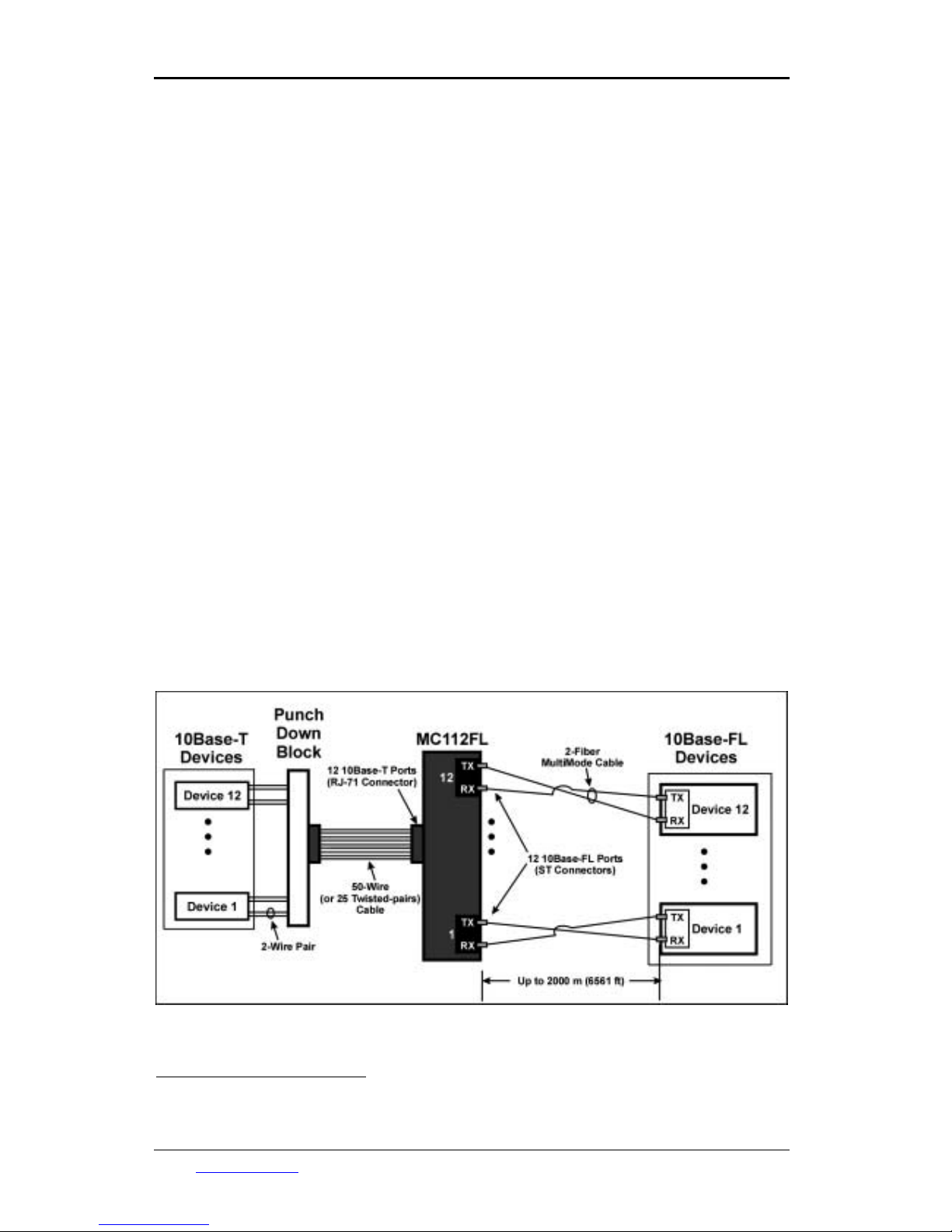
An MC112FL is used to interconnect up to 12 devices having Ethernet/IEEE 802.3 10Base-T
ports to as many devices having Ethernet/IEEE 802.3j 10Base-FL ports, as shown in Figure 1,
and to extend their operating range which can reach up to 2000 m (6561 ft).
Figure 1: Application of MC112FL
2
LIN cuts off transmission to the other side of the MC112FL when it does not receive from one
side.
URL: http://www.mrv.com 8
Page 9
MC112FL User Manual ML47766, Rev. 02 July 2007
Layout
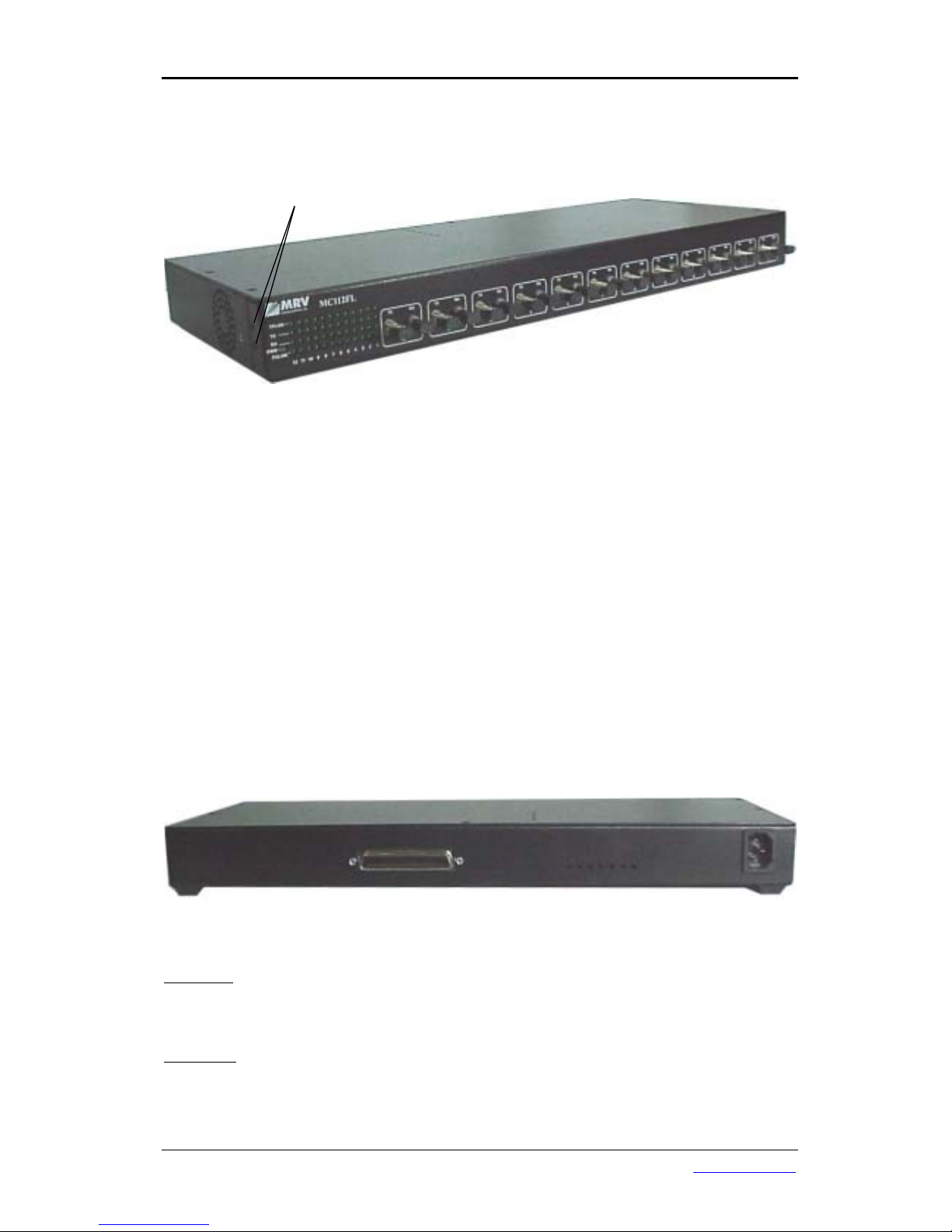
Front
View
Bracket Screws
Figure 2: Front View of MC112FL
Ports
12 Tx and 12 Rx Ethernet/IEEE 802.3j 10Base-FL ports with ST connectors. The ports (TX, RX
pair) are numbered 12 to 1 going from left to right. The requirements of the fiberoptic cables to be
connected to these ports are given in Appendix A: Cable Requirements.
LED Indicators
Global Status LED
• PWR – Power status
Per-Port Status LEDs
• TPLINK – 10Base-T port link status.
• TX –10Base-FL Tx port transmission status.
• RX –10Base-FL Rx port reception status.
• FOLINK – 10Base-FL port link status
For details on the LEDs, refer to Table 1 in the section Operation.
Rear
View
Figure 3: Rear View of MC112FL
Ports
Data Ports
Twelve 4-pin Ethernet/IEEE 802.3 10Base-T ports fitted with a Champ 50-pin connector (RJ71).
The requirements of the electrical data cables to be connected to these ports are given in
Appendix A: Cable Requirements.
Power Port
3-prong receptacle for 100 to 240 Vac, 60/50 Hz line (mains) power input.
9 URL: http://www.mrv.com
Page 10

MC112FL User Manual ML47766, Rev. 02 July 2007
Installation
Safety
Before installing the MC112FL, ensure that the requirements noted in the section Safety
Requirements are met.
Package Contents
• MC112FLs
• Power Cords (1 per MC112FL)
• 2 Rack Mount Brackets
• CD containing User Manual
Requirements
Tools & Equipment
• 6-in flat-tip screwdriver
• 6-in Philips screwdriver
• 4 rack-mount screws
• 50-wire feeder cable with male Champ 50-pin connector for interconnecting the
MC112FL female Champ connector and 10Base-T compliant devices or Punch Down
Block.
Mounting
• 443 mm x 44 mm x 179 mm (19 in x 1U
3
x 7 in) space in a 19-inch rack
or
• Flat, stable, non-conductive, static-free surface (e.g., desktop or shelf).
Power
The MC112FL has a Universal (wide-range) internal power supply that can accept any voltage
from a power source in the range 100 to 240 Vac at 60/50 Hz. The power source must be able to
deliver:
100 to 240 Vac, 0.8 A at 60/50 Hz
Device
The device ports must operate at 10 Mbps in full-duplex or in half-duplex mode; and not in Autonegotiation mode.
The device ports to be connected to the MC112FL Champ connector must be 10Base-T
compliant. The device ports to be connected to the MC112FL fiberoptic ST connectors must be
10Base-FL compliant.
Cabling
The cables must meet the specifications given in Appendix A: Cable Requirements.
Accessories
The following accessories can be used with the MC112FL.
• Punch Down Block (50-pin)
• Up to twelve 4-wire cables for interconnecting the Punch Down Block and 10Base-T
compliant device ports.
3
1U = 1¾ inch or 44.45 mm
URL: http://www.mrv.com 10
Page 11

MC112FL User Manual ML47766, Rev. 02 July 2007
Procedure
Unpacking and Inspection
Unpack the MC112FLs as follows:
1. Examine the shipping box for damage. If it is damaged, request the carrier to remain
present.
2. Open the shipping box without damaging it.
3. Remove the MC112FL(s) and visually inspect them for external damage such as
scratches, dents, or dislodged components. If an MC112FL is damaged, notify the
carrier’s agent and contact your MRV representative.
Mounting
Mount the MC112FL in a rack or place it on a surface as described below.
Rack
1. Make sure that the MC112FL is not connected to a power source.
2. Undo the four Bracket Screws (two on each side of the MC112FL) shown in Figure 2.
3. Fasten the two Mounting Brackets to the sides of the MC112FL with the Bracket Screws.
4. Mount the MC112FL in a 19-inch rack using four Rack Screws.
Surface
Place the MC112FL on a flat, stable, non-conductive static-free surface, e.g., desktop or shelf.
Power Line Connection
To power up the MC112FL:
1. Connect one end of the power cord to the MC112FL.
2. Connect the other end of the power cord to the power source (line/mains).
Cabling
Electrical
1. Attach the male Champ 50-pin connector of a feeder cable to the female Champ 50-pin
connector of the MC112FL.
2. Attach the other end of the feeder cable to the 10Base-T compliant devices or Punch
Down Block (if used).
3. If a Punch Down Block is used, connect it to 10Base-T compliant device ports with 4-wire
cables.
4. Ensure that the devices with the 10Base-T compliant ports are powered ON.
Fiberoptic
1. For each cable fiber, attach a label with the marking TX at one end and another label with
the marking RX at the other end.
2. Remove the protective plastic caps from the fiberoptic ports to be connected.
3. Connect the MC112FL ports to the device ports with fiberoptic cables as shown in Figure
1, ensuring that for each cable fiber, the end marked TX is connected to a TX port and
the end marked RX is connected to an RX port.
4. Ensure that the devices with the 10Base-FL compliant ports are powered ON.
Verification
1. For each connected MC112FL port, verify that its associated LED TPLINK is ON.
For each connected 10Base-T compliant port of the attached device, verify that its
associated link LED is ON.
If a TPLINK LED is OFF, ensure that the:
11 URL: http://www.mrv.com
Page 12

MC112FL User Manual ML47766, Rev. 02 July 2007
a. MC112FL and device are receiving power.
b. Cable interconnecting the MC112FL and device is properly connected.
c. The cable is undamaged.
d. The cable is correctly wired.
2. For each connected MC112FL port, verify that its associated LED FOLINK is ON.
For each connected 10Base-FL compliant port of the attached device, verify that its
associated link LED is ON.
If an FOLINK LED is OFF, ensure that the:
a. Device at the other end is receiving power.
b. Cable interconnecting the MC112FL and device is properly connected, i.e., for
each fiber, one end is attached to a TX port and the other end is attached to an
RX port.
c. The cable is undamaged.
d. Power attenuation of the cables does not exceed the specification in the section
10Base-FL MultiMode Cable on page 14.
3. Verify that 10Base-T device Link LED is ON.
If the device Link LED is OFF, ensure that the:
a. Device at the other end is receiving power.
b. The copper cable to the device is properly connected to the MC112FL copper
port.
c. The fiberoptic cable from the other device to the MC112FL fiberoptic port is
properly connected.
4. Verify that 10Base-FL device Link LED is ON.
If the device Link LED is OFF, ensure that the:
a. Device at the other end is receiving power.
b. The fiberoptic cable from the MC112FL to the 10Base-FL fiberoptic port is
properly connected.
c. The copper cable from the 10Base-T device to the MC112FL copper port is
properly connected.
URL: http://www.mrv.com 12
Page 13
MC112FL User Manual ML47766, Rev. 02 July 2007
Operation
Monitoring
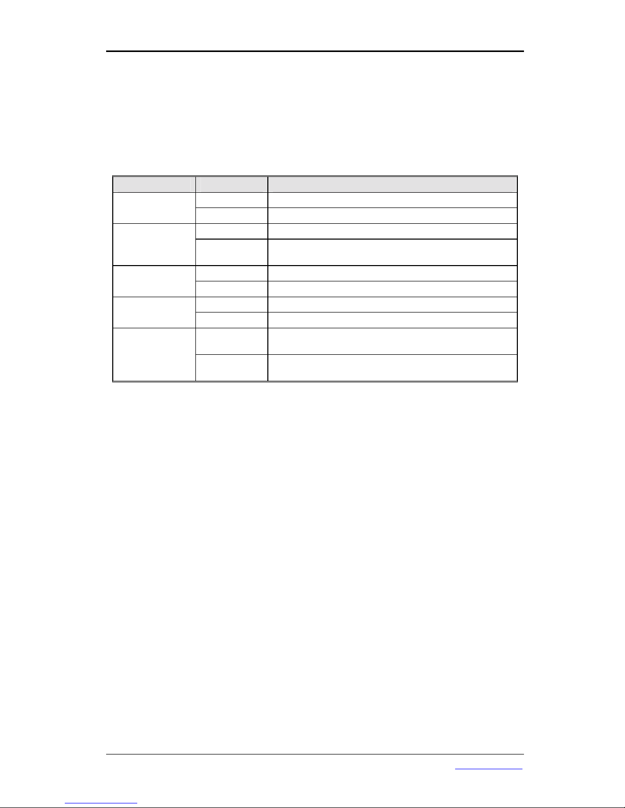
The MC112FL becomes fully operational within a few seconds after being powered on. Its
operation can be monitored by interpreting the status of its LEDs with the aid of Table 1.
Table 1: MC112FL Front Panel LEDs
LED Status Significance
ON Power to MC112FL OK. PWR
OFF Power to MC112FL faulty.
ON Port link to device via the twisted-pair cable OK. TPLINK
OFF
Port link to device via the twisted-pair cable absent or
faulty.
ON/BLINKING 10Base-FL Tx port transmitting data. TX
OFF 10Base-FL Tx port not transmitting data.
ON/BLINKING 10Base-FL Rx port receiving data. RX
OFF 10Base-FL Rx port not receiving data.
ON
10Base-FL port link to remote MC112FL via the
fiberoptic cable OK.
FOLINK
OFF
10Base-FL port link to remote MC112FL faulty or
absent.
Connectivity Verification
Verify connectivity by sending data traffic between the devices interconnected with the MC112FL.
13 URL: http://www.mrv.com
Page 14
MC112FL User Manual ML47766, Rev. 02 July 2007
Appendix A: Cable Requirements
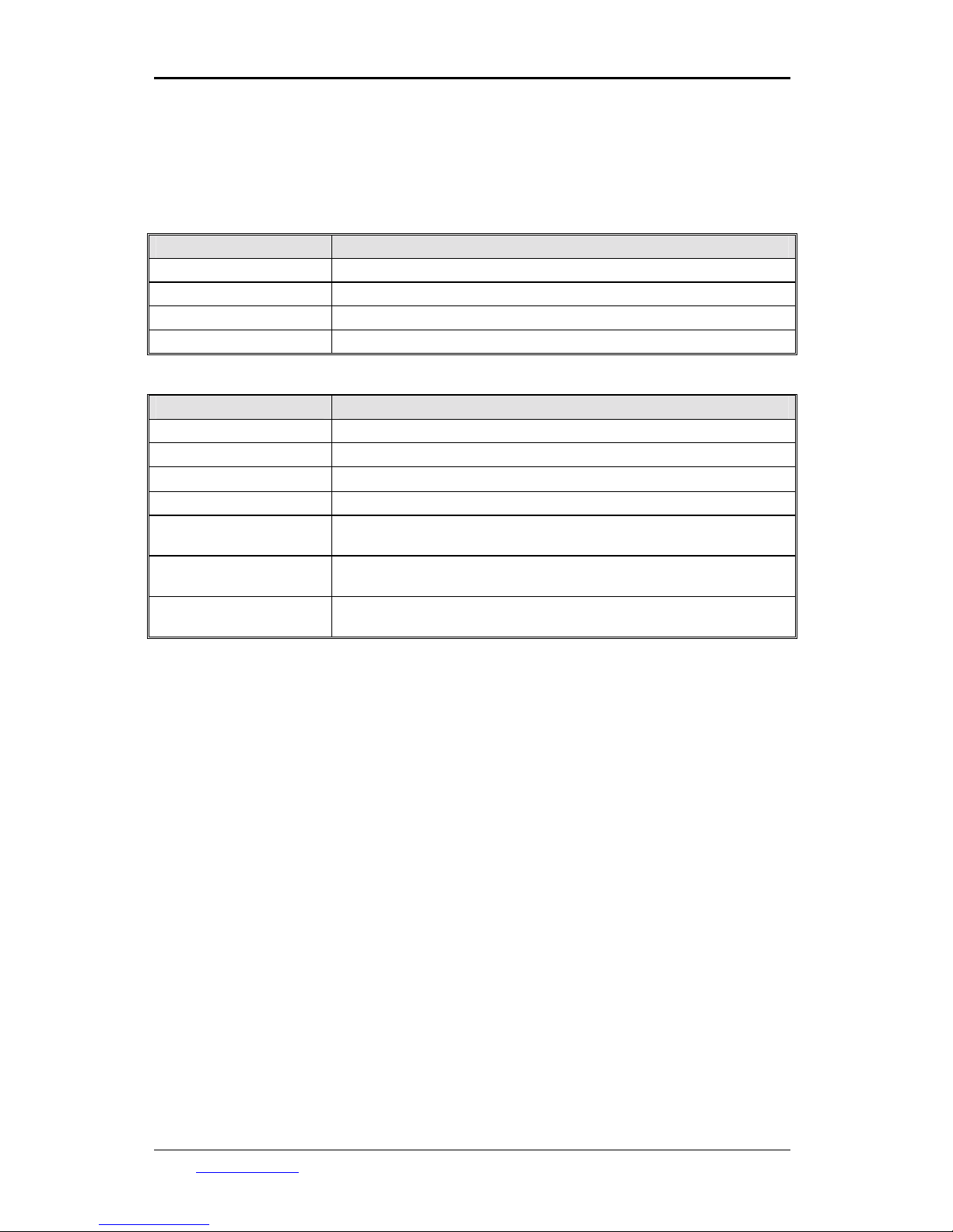
This appendix specifies the cable requirements for the 10Base-T and 10Base-FL ports of the
MC112FL.
10Base-T Twisted-Pair Cable
Parameter Value
Cable Type 50-wire (25 twisted-pairs) cable.
Connector Type Male Champ 50-pin (RJ-71).
Wire Gage 24 (or smaller) AWG.
Cable Length Per the cable quality.
10Base-FL MultiMode Cable
Parameter Value
Cable Type MultiMode.
Connector Type Male ST.
Core/Cladding Diameters
62.5/125 µm
Segment Length 0 to 2000 meters (6561 feet) per the IEEE 10Base-FL standard.
Segment Insertion Loss
(Max)
Not exceeding 12.5 dB as measured using an optical signal source
having center wavelength 850 nm and spectral width 75 nm.
Optical Connector
Insertion Loss
Not exceeding 1 dB.
Cable Attenuation
Not exceeding 3.75 dB/km, when measured at a wavelength of 850
nm using a 62.5/125 mm fiber.
URL: http://www.mrv.com 14
Page 15

MC112FL User Manual ML47766, Rev. 02 July 2007
Appendix B: Cleaning Optical Connectors
General
Intrusions (e.g., dust, grease, etc.) at the interface of two optical fibers, such as at a pair of
coupled connectors, attenuate the signal through the fiber. Consequently, optical connectors
must be cleaned before they are coupled with other connectors.
Tools and Equipment
Following are tools and equipment required for cleaning connectors.
Dust caps
Caps for protecting the connector from intrusions. A cap is usually made from flexible plastic.
When placing a cap over a connector, avoid pressing it against the fiber ferula surface in the
connector so as to prevent contamination.
Isopropyl alcohol
Solvent for contaminants.
Tissues
Soft multi-layered fabric made from non-recycled cellulose.
Procedure
The procedure for cleaning connectors is as follows:
1. If no stains are present, using a new clean dry tissue, gently rub, in small circular
motions, the exposed fiber surface and surrounding area in the connector to remove
dust.
2. If stains are present, moisten a new clean dry tissue with isopropyl alcohol and gently
rub, in small circular motions, the exposed fiber surface and surrounding area in the
connector to remove the stains.
Using a new clean dry tissue, gently rub, in small circular motions, the exposed fiber
surface and surrounding area in the connector to remove the dissolved stains and excess
isopropyl alcohol.
3. If a connector is not to be coupled with another immediately, cover it with a dust cap.
15 URL: http://www.mrv.com
Page 16
MC112FL User Manual ML47766, Rev. 02 July 2007
Appendix C: Product Specification
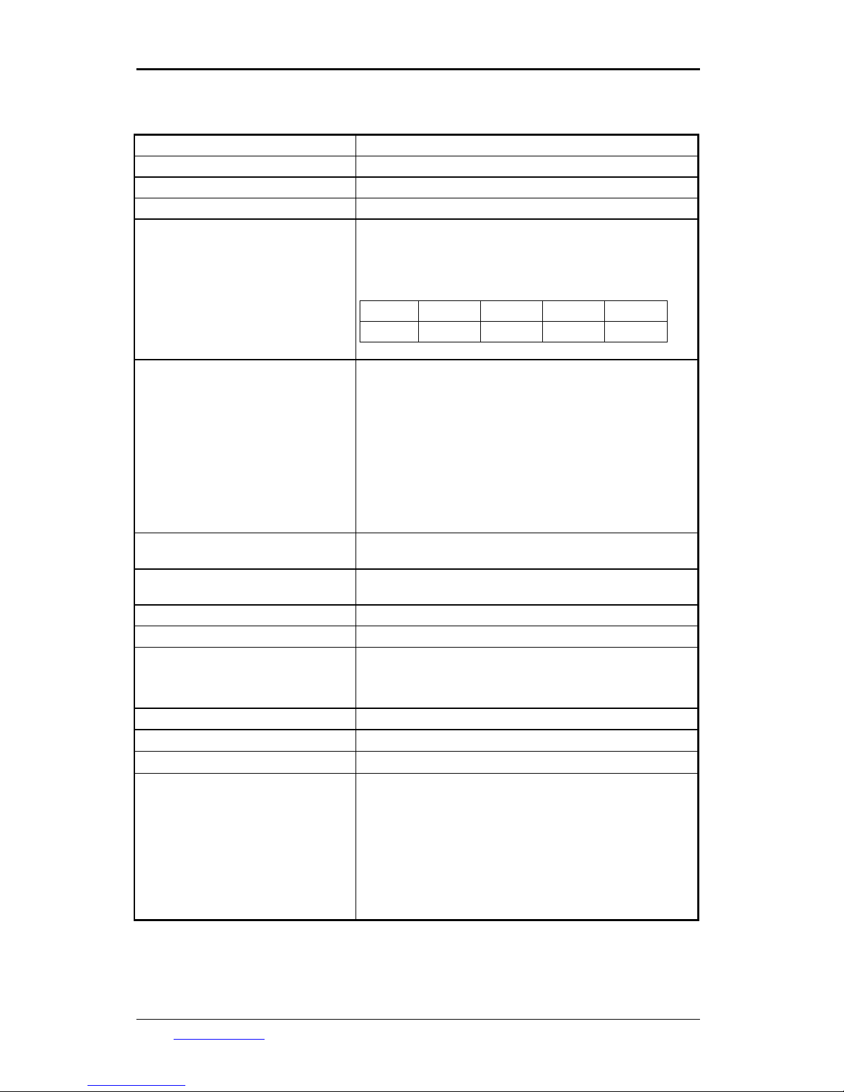
Function Media converter
Protocol Conversion 10Base-T !" 10Base-FL
Network Topology Point-to-point
Operating Distance (max) 2100 m (6889 ft)
Electrical Data Port
Protocol
Supported Speed
Connector Type
Connector Pinout (for Port k,
where k = 1 or 2 … or 12)
(Example: Port 3 signals/pins are:
TX+/30, TX-/5, RX+/31, RX-/6)
10Base-T
10 Mbps
Female RJ-71 (Champ 50-pin)
Signal
TX+ TX- RX+ RX-
Pin
24 + 2k 2k - 1 25 + 2k 2k
Pins 25 and 50 are not used.
Fiberoptic Data Port
Protocol
Supported Speed
Operating Distance (max)
Connector Type
Cable Fiber Core/Cladding
Diameters
Operating Wavelength
10Base-FL
10 Mbps
2000 m (6561 ft) at 3.75 dB/km with 62.5/125 µm cable
fiber core/cladding diameters
Female ST
62.5/125 µm
850 nm
Electrical Data Cable
Refer to the section 10Base-T Twisted-Pair Cable on
page 14.
Fiberoptic Data Cable
Refer to the section 10Base-FL MultiMode Cable on page
14.
Power Input 100 to 240 Vac, 0.8 A at 60/50 Hz
Power Consumption (max) 30 W
Temperature:
Operating
Storage
0 to 40
O
C (32 to 104 OF)
-30 to 90OC (-22 to 194 OF)
Humidity (non-condensing) 5 to 90%
Dimensions (W x H x D) 443 mm x 44 mm x 179 mm (19 in x 1U x 7 in)
Weight (max) 2 kg (4.4 lb)
Compliance
Safety
EMI
EMC
Protocol
Designed to comply with UL 1950; CSA 22.2 No. 950; EN
60950
Designed to comply with FCC Part 15 Class B; EN 55022
Class B
Designed to comply with EN 50082-1.
Designed to comply with Ethernet/IEEE 802.3 10Base-T
and Ethernet/IEEE 802.3j 10Base-FL
1U = 1.75 in.
URL: http://www.mrv.com 16
 Loading...