

Page 1
Getting Started with the LX-4000 Series
Corporate Headquarters
MRV Communications, Inc. Corporate Center
20415 Nordhoff Street
Chatsworth, CA 91311
Tel: 818-773-0900
Fax: 818-773-0906
www.mrv.com
MRV Americas Service and Support
295 Foster Street
Littleton, MA 01460
Tel: 800-435-7997
Tel: +001 978-952-4888 (Outside U.S.)
Email: [email protected]
(Internet)
MRV America Sales
295 Foster Street
Littleton, MA 01460
Tel: 800-338-5316 (U.S.)
Email: sales@mrv .com
MRV International Sales
Business Park Moerfelden
Waldeckerstrasse 13
64546 Moerfelden-Walldorf
Germany
Tel: (49) 6105/2070
Fax: (49) 6105/207-100
Email: [email protected]
451-0308P
Page 2

All rights reserved. No part of this publication may be reproduced without the prior written consent of
MRV Communications, Inc. The information in this document is subject to change without notice and
should not be construed as a commitment by MRV Communications, Inc. MRV Communications, Inc.
reserves the right to revise this publication, and to make changes in content from time to time,
without obligation to provide notification of such revision or changes. MRV Communications, Inc.
assumes no responsibility for errors that may appear in this document.
Copyright © 2006 by MRV Communications, Inc.
Should you experience trouble with this equipment, please contact one of the following support
locations:
• If you purchased your equipment in the Americas, contact MRV Americas Service and
Support in the U.S. at 978-952-4888. (If you are calling from outside the U.S., call +011 978952-4888.)
• If you purchased your equipment outside the Americas (Europe, EU, Middle-East,
Africa, Asia), contact MRV International Service and Support at 972-4-993-6200.
FCC Notice
CAUTION
This equipment has been tested and found to comply with the limits for a
Class A digital device, pursuant to Part 15 of the FCC Rules. These limits
are designed to provide reasonable protection against harmful interference
when the equipment is operated in a residential installation. This
equipment generates, uses, and can radiate radio frequency energy and, if
not installed and used in accordance with the instructions, can cause
harmful interference to radio communications. However, there is no
guarantee that interference will not occur in a particular installation. If
this equipment does cause harmful interference to radio or television
reception, which can be determined by turning the equipment off and on,
the user is encouraged to try to correct the interference by one or more of
the following measures:
• Reorient or relocate the receiving antenna.
• Increase the separation between the equipment and receiver.
• Connect the power cord of the equipment into an outlet on a circuit that
is different from that to which the receiver is connected.
• Consult the dealer or experienced radio/TV technician for help.
Changes or modifications not expressly approved by MRV Communications,
Inc. could void the user's authority to operate the equipment.
2 MRV Communications, Inc. www.mrv.com 451-0308
Page 3
BSMI Notice
VCCI Notice
This is a Class A product based on the standard of the Voluntary Control Council for
Interference by Information Technology Equipment (VCCI). If this equipment is used in a
domestic environment, radio disturbance may arise. When such trouble occurs, the user may
be required to take corrective actions.
EXPORT NOTICE
MRV models contain 128-bit encryption software. Export of this product is restricted under U.S. law.
Information is available from the U.S. Department of Commerce, Bureau of Export Administration at
www.bis.doc.gov.
Licensing Notice
This software is licensed as described in the "License" file on the LX-Series CD Kit and at the MRV
website when downloading software.
451-0308 MRV Communications, Inc. www.mrv.com 3
Page 4

4 MRV Communications, Inc. www.mrv.com 451-0308
Page 5

Table of Contents
Preface................................................................................................................................... 11
Customer Support ..............................................................................................................................11
Other Documentation ........................................................................................................................12
Overview of the LX-4000 Series........................................................................................... 13
Conventions ........................................................................................................................................13
System Specifications ........................................................................................................................14
Installing the LX-4000 Series............................................................................................... 15
Hardware Installation .......................................................................................................................15
Unpack and Inspect the Unit ....................................................................................................... 15
Package Contents .......................................................................................................................... 15
LX-4000 Indicators and Interfaces....................................................................................................16
Front Panel LEDs ......................................................................................................................... 16
Rear Panel LEDs .......................................................................................................................... 17
Environmental and Installation Considerations..............................................................................19
Mounting the Unit into a 19-inch or 23-inch Rack ..........................................................................20
Cable Connections..............................................................................................................................20
Connect the Power Cable .............................................................................................................. 20
Connecting the Ethernet Interface............................................................................................... 20
Connect Serial Device Cables ....................................................................................................... 21
Connecting Your Management Station........................................................................................ 21
Connecting DC Power ................................................................................................................... 21
Modem Port (Optional) ......................................................................................................................22
Powering On .......................................................................................................................................22
System Login and Passwords ............................................................................................................23
Resetting the Unit..............................................................................................................................23
Configuring the LX-4000 Series for the First Time............................................................ 25
Configuring the LX-4000 Unit for the First Time ............................................................................25
First Time Quick Configuration ................................................................................................... 25
Assigning an IP Address via the Network ................................................................................... 27
Manually Setting the IP Address Via the CLI .................................................................................28
Accessing and Configuring the Graphical User Interface (GUI) ....................................................28
Web Configure Mode ..................................................................................................................... 31
Web Access Mode........................................................................................................................... 32
Menu/Config Mode ........................................................................................................................ 32
GUI EZ Configuration........................................................................................................................33
Launching the EZConfig GUI....................................................................................................... 33
Software Upgrades.............................................................................................................................34
IP Configuration Menu ......................................................................................................................34
Booting from Defaults........................................................................................................................34
Accessing and Configuring Additional Features ..............................................................................34
Connecting to the LX-4000 Series via Telnet or SSH ................................................................. 34
Accessing from a Terminal Attached to an LX-4000 Series Serial Port .................................... 35
Additional Considerations .................................................................................................................35
Command Line Interface (CLI) Tree Structure................................................................................36
Additional Considerations for an Internet Environment ................................................................36
451-0308 MRV Communications, Inc. www.mrv.com 5
Page 6

Autobauding Feature .........................................................................................................................36
Reinitializing/Powering Off the Unit ................................................................................................36
Alternative Port Capabilities................................................................................................ 37
Sensor (Temperature/Humidity) Ports .............................................................................................37
Connecting the Temperature/Humidity Sensor .......................................................................... 37
5250 Power Management ..................................................................................................................38
Connecting the 5250...................................................................................................................... 39
5150 Power Strip Management .........................................................................................................40
Connecting the 5150...................................................................................................................... 40
4800 Power Strip Management .........................................................................................................41
Connecting the 4800...................................................................................................................... 41
Using LX Ports as Alarm Inputs and Control Outputs ...................................................................42
Alarm Inputs Setup and Usage .................................................................................................... 42
Control Output Setup and Usage ................................................................................................. 43
Appendix A - Technical Specifications............................................................................... 45
Appendix B - Factory Defaults............................................................................................. 49
ppciboot Factory Default Settings.....................................................................................................50
Appendix C - POST Test Error Codes................................................................................. 51
Error Code Definitions.......................................................................................................................51
POST Test Error Code Sample..........................................................................................................53
Appendix D - Cabling the LX-4000 Series........................................................................... 55
Cabling Considerations......................................................................................................................55
Serial Device Connectors .............................................................................................................. 55
Diagnostic Port Connector (Port 0) .............................................................................................. 55
10/100 Connector........................................................................................................................... 56
Ordering Cables ............................................................................................................................ 56
Modular Adapters ..............................................................................................................................56
Pin Assignments............................................................................................................................ 56
Ordering and Installing the Inlet Connector Lock ...........................................................................58
Connecting to the Diagnostic Port (Port 0).......................................................................................58
Modem Control/Hardware Flow Control ..........................................................................................58
RJ-45 Wiring Considerations ............................................................................................................59
Modular Adapters (RJ-45 to DB-25) .................................................................................................59
MRV 8-Wire Cabling..........................................................................................................................61
6 MRV Communications, Inc. www.mrv.com 451-0308
Page 7

Figures
LX Series 4008 Front Panel ....................................................................................................... 16
LX Series 4016 Front Panel ....................................................................................................... 16
LX Series 4032 Front Panel ....................................................................................................... 16
LX Series 4048 Front Panel ....................................................................................................... 16
LX Series 4008 Rear Panel ........................................................................................................ 17
LX Series 4008 with Modem Rear Panel ................................................................................... 17
LX Series 4016 with Modem Rear Panel ................................................................................... 18
LX Series 4016 DC Version Rear Panel..................................................................................... 18
LX Series 4032 with Modem Rear Panel ................................................................................... 18
LX Series 4032 DC Version with Modem Rear Panel ............................................................... 19
LX Series 4048 AC Rear Panel................................................................................................... 19
Mounting an LX-4000 Series in Rack ........................................................................................ 20
Connecting DC Power ................................................................................................................. 21
LX Series RESET Switch Location ............................................................................................ 23
Basic Menu Structure ................................................................................................................. 36
Connecting the Temperature/Humidity Sensor ........................................................................ 38
Connecting the 5250 ................................................................................................................... 39
Connecting the 5150 ................................................................................................................... 40
Connecting the 4800 ................................................................................................................... 41
Typical Alarm Inputs Connections ............................................................................................ 43
Typical Interface Design for Control Output Signals ............................................................... 44
POST Test Error Code Sample................................................................................................... 54
Serial Device Connector (RJ-45) Signal Assignments .............................................................. 55
10/100 Connector Assignments .................................................................................................. 56
DB-25 Pins................................................................................................................................... 57
Installing the Inlet Connector Lock ........................................................................................... 58
Adapter Wiring, LX Series to DTE ............................................................................................ 59
Adapter Wiring, RJ-45 to DB-9, LX Series to DTE ................................................................... 60
Adapter Wiring, LX Series to DCE ............................................................................................ 60
Adapter Wiring, LX-Series to DCE, with RING........................................................................ 61
Modular Cables for RTS/CTS Flow Control (Eight-Wire), Concurrent with Modem Control Sig-
nalling.......................................................................................................................................... 62
451-0308 MRV Communications, Inc. www.mrv.com 7
Page 8

8 MRV Communications, Inc. www.mrv.com 451-0308
Page 9

Tables
LX-4000 Series Specifications .................................................................................................... 45
Temperature/Humidity Sensor Specifications .......................................................................... 48
LX-4000 Series Factory Defaults ...............................................................................................49
POST Test Error Codes .............................................................................................................. 51
451-0308 MRV Communications, Inc. www.mrv.com 9
Page 10

10 MRV Communications, Inc. www.mrv.com 451-0308
Page 11

Preface
This guide contains all the information you need to get the LX-4000 Series up and running.
This guide is organized as follows:
•Preface - Describes the manual’s organization and how to contact customer support.
• Chapter 1 – Provides an overview of the LX-4000 Series, including supported communication
speeds, software requirements, and conventions.
• Chapter 2 – Describes how to install and connect the LX-4000 Series, as well as the unit’s
LEDs and connectors.
• Chapter 3 – Explains how to configure the unit for the first time, access the Graphical User
Interface, install Java Runtime Environment (JRE), and connect to the LX-4000 Series via
telnet and SSH.
• Chapter 4 – Describes alternative port capabilities, including temperature/humidity sensors,
4800/5150 power control units, and using LX ports as alarm input and control output port
points.
• Appendix A – Provides the electrical, environmental, and physical requirements for the LX4000 Series installation.
• Appendix B - Lists the factory default settings.
• Appendix C – Provides the error code definitions for the POST test error codes.
• Appendix D - Describes how to cable the LX-4000 Series unit.
Customer Support
Should you experience trouble with this equipment, please contact your MRV Americas Service and
Support customer representative in the USA at 978-952-4888. International customers call +011 978952-4888.
451-0308 MRV Communications, Inc. www.mrv.com 11
Page 12

Preface
Other Documentation
Other manuals in the LX documentation set are:
• LX-Series Commands Reference Guide - Describes each individual command in the LX CLI
tree.
• LX-Series Configuration Guide - Provides information on network configuration, initial setup,
how to set up for remote console functions, RADIUS, and system administration. Provides
basic information regarding the Network Management System (NMS), and procedures on how
to use the Management Information Base (MIB) structure (as pointers to objects in the
devices) to manage these units.
• Software Release Notes - Cites supported features as well as any notes and restrictions for the
current software version.
12
MRV Communications, Inc. www.mrv.com 451-0308
Page 13

Chapter 1
Overview of the LX-4000 Series
The LX-4000 Series is a secure standalone communication server that is designed for applications
requiring secure console or serial port management. The LX-4000 Series provides the most secure and
robust feature set to meet your remote console management and terminal server needs. The LX-4000
Series includes the most comprehensive security features, such as per port access protection,
RADIUS, Secure Shell v2.0, PPP PAP/CHAP, PPP dial-back, on-board database, menus, and others.
The LX-4000 Series console management solution enables centrally located or remote personnel to
connect to the console or craft ports of any network element or server. This serial connection allows
administrators to manage and configure the remote network devices and servers, as well as perform
software upgrades as if attached locally.
The LX-4000 Series also provides various port densities of RS-232 DTE RJ45 Serial ports, as well as
V.90/K56 flex Internal Modem options. Currently, the LX-4000 hardware provides port densities of 8,
16, 32, and 48 ports, plus port 0 for local management.
Conventions
The following conventions are used throughout this guide:
• User prompt – The user prompt is (for example) InReach:0> for Non-superusers or InReach:0>>
for superusers. The prompt will change based on a login user profile, as configured by the
Superuser. The 0 represents the session number.
451-0308 MRV Communications, Inc. www.mrv.com 13
Page 14
Overview of the LX-4000 Series
• Configure Mode prompt – A sample configure mode prompt is Async 1-6:0 >>, where
Async is a reminder that tells you which part of the configuration you are in, 1-6 is the range
of ports any operation will affect, 0 is a session number, and >> indicates superuser mode. To
get to the Async 1-6:0 >> prompt, you must first type port async 1 6 at the Config:0
>> prompt. Note that you do not add a dash between the range numbers in port async 1 6.
• Command execution – Unless otherwise specified, commands are executed when you press
<RETURN>.
• Keyboard characters (keys) – Keyboard characters are represented using left and right
angle brackets (< and >). For example, the notation <CTRL> refers to the CTRL key; <A>
refers to the letter A; and <Enter> refers to the RETURN key.
• Typographical conventions – The following typographical conventions are used:
Monospace Typeface – indicates text that can be displayed or typed at a terminal (i.e.,
displays, user input, messages, prompts, etc.).
italics – are used to indicate variables in command syntax descriptions.
• Help Key (?) - At any prompt level, you can press ? to display the available commands at
that level. The only time this is not true is if you are in the midst of entering a command. If ?
is at the end of a partial command, the LX displays a list of valid arguments to assist you in
adding to the current command line.
• Tab - Press the Tab button to complete a partially entered command. You must enter the first
three characters of a command for autocomplete to work. If the command is already complete,
the Tab button displays available commands.
• Command Recall - The up arrow recalls previously used commands.
• Ctrl-F – Moves forward to the next session.
• Ctrl-B – Moves back to the previous session.
• Ctrl-L – Returns you to the Local Command Mode.
• Ctrl-K – Clears the current command line.
NOTE:You must press the Enter key after you type Ctrl-F, Ctrl-B, Ctrl-L, or Ctrl-K.
System Specifications
The following table lists important system specifications:
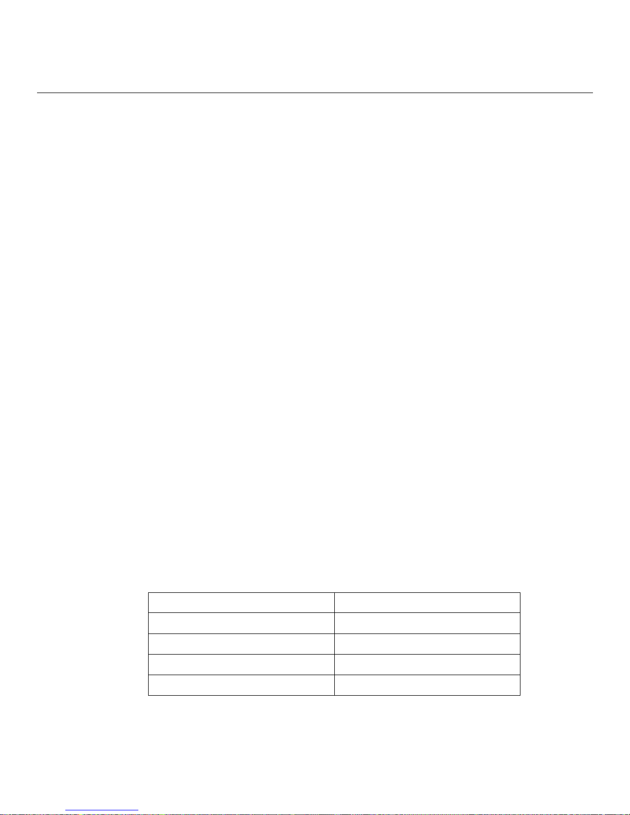
Item Description
Interface DTE RS-232 - RJ-45
Serial Line Speed 134.5 bps to 230 Kbps
Ethernet Interface 10/100 Auto Sensing
Default Serial Line Speed 9600 bps
14
MRV Communications, Inc. www.mrv.com 451-0308
Page 15

Hardware Installation
This section explains how to install an LX-4000 Series Communications server and place it into
operation.
Unpack and Inspect the Unit
Place all packing materials back into the shipping carton and save the carton. (If you need to return
the unit to MRV or your distributor, you should return it in the original carton.)
Package Contents
The LX-4000 unit shipping carton contains the following items:
• One rack mounting kit. MRV provides the following mounting screws: Eight 6-32 x 5/16”
flathead screws for attaching the ears to the unit, and four 10-32 screws to attach to the rack.
• One power cord appropriate to your particular LX model.
• One 8-wire RJ-45 serial crossover cable.
Chapter 2
Installing the LX-4000 Series
• One female DB-9 to RJ-45 adapter.
• One software/documentation CD.
451-0308 MRV Communications, Inc. www.mrv.com 15
Page 16
Installing the LX-4000 Series
LX-4000 Indicators and Interfaces
This section explains the LX-4000 unit’s indicators and interfaces.
Front Panel LEDs
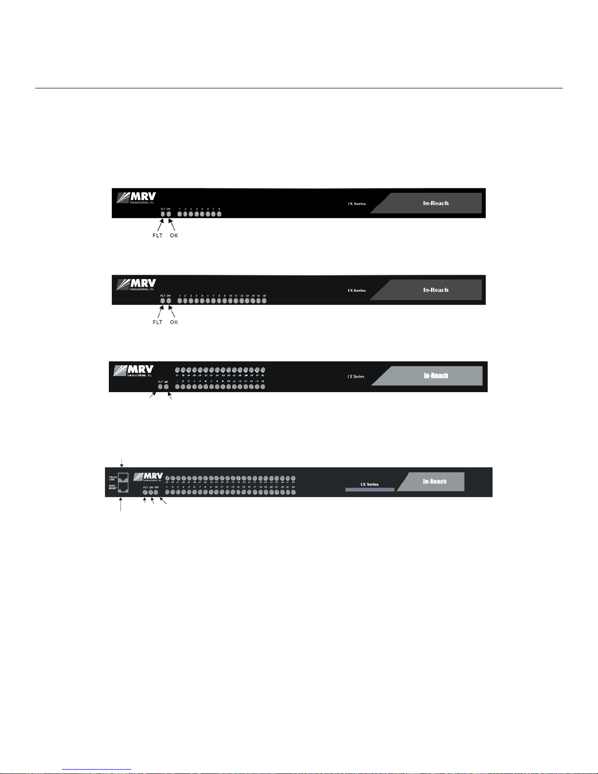
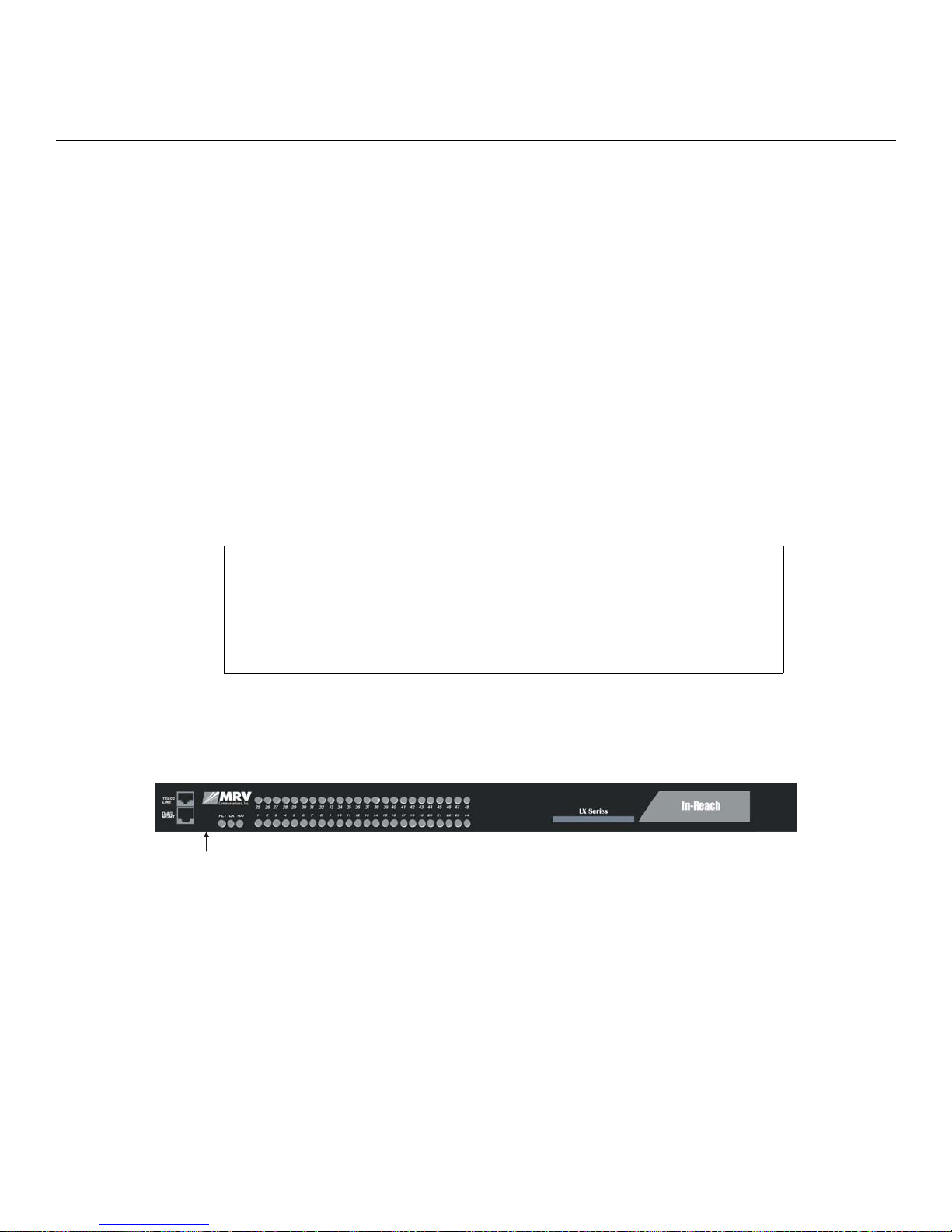
This section explains the front panel LEDs (see Figures 1 through 4).
Figure 1 - LX Series 4008 Front Panel
Figure 2 - LX Series 4016 Front Panel
FLT
OK
Figure 3 - LX Series 4032 Front Panel
Modem Port
DIAG Port (Port 0)
FLT
100 Mbps LED
OK
Figure 4 - LX Series 4048 Front Panel
FLT
Solid red indicates a fault condition exists or maintenance is required. This LED remains on until the
initial Power On Self Test (POST) completes successfully.
OK
Solid green indicates the system’s voltages are normal and the unit has passed the POST test.
16
MRV Communications, Inc. www.mrv.com 451-0308
Page 17
Port Status LEDs
D
K
Each of the eight (or 16, or 32, or 48) green LEDs flash when receive, transmit, or status activity is
detected on its corresponding serial port. The port status LEDs are used in several ways. During the
initialization process, the LEDs indicate self-tests are being performed, and if any self-test fails, they
indicate an error code. After a POST test and a system software boot, the lights indicate when a port
is actively being used.
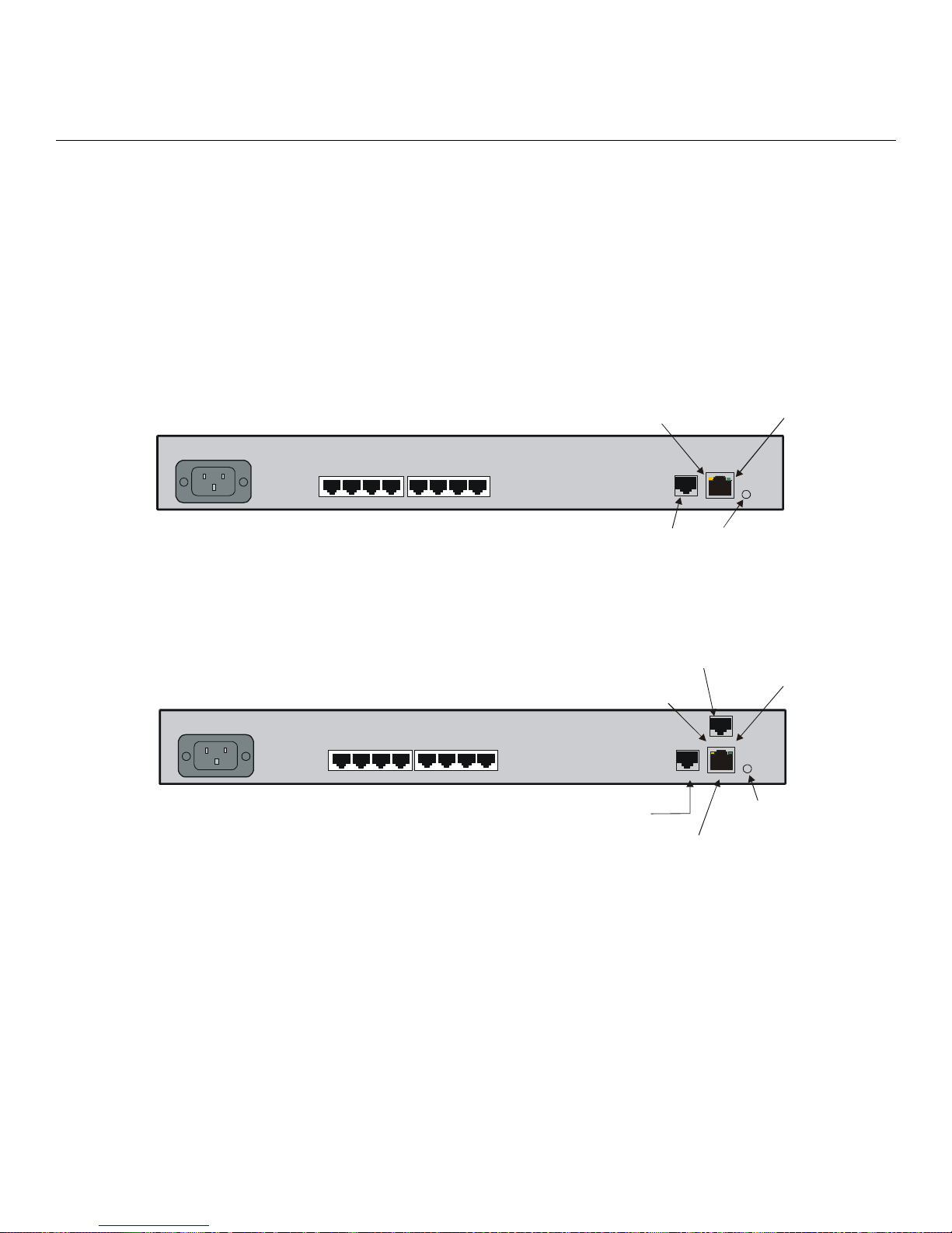
Rear Panel LEDs
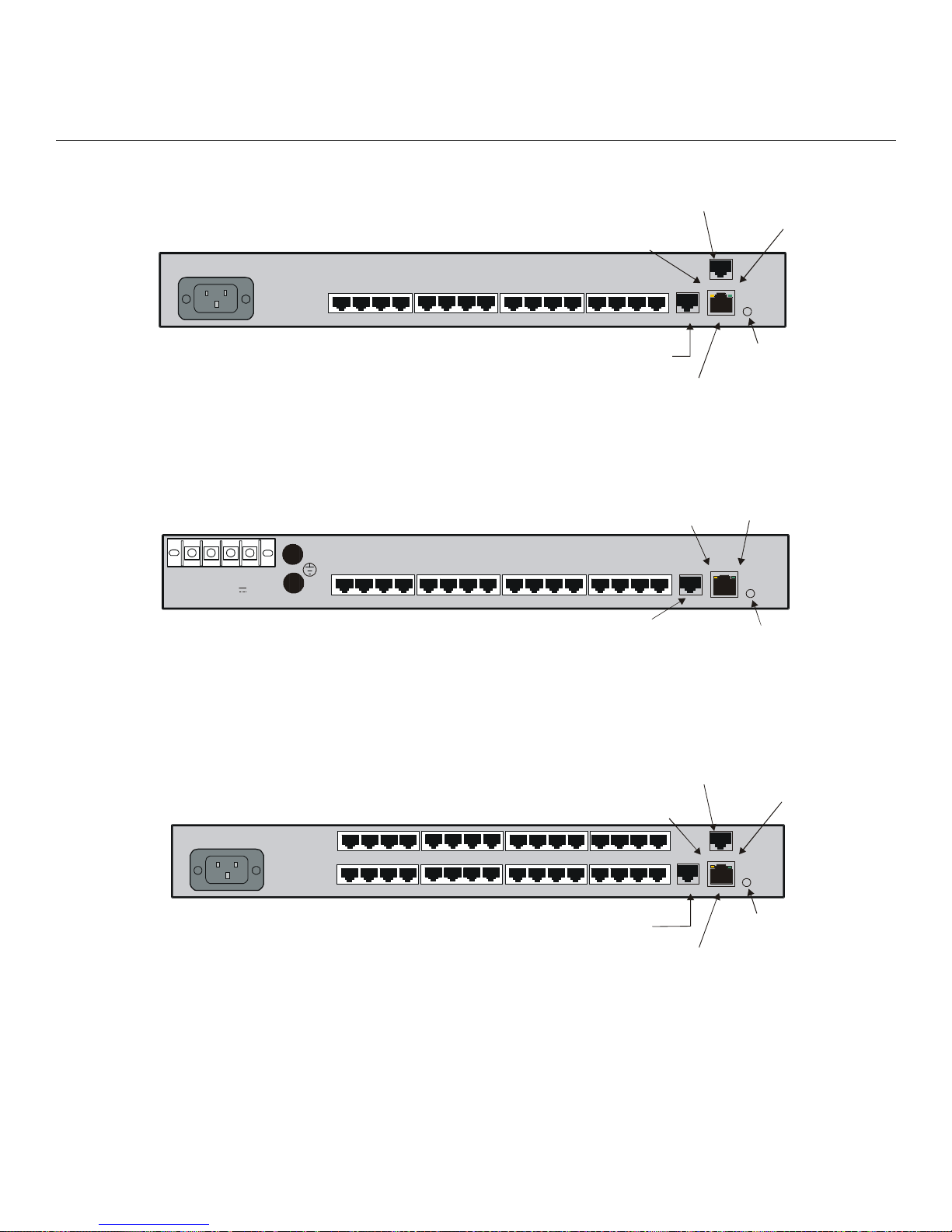
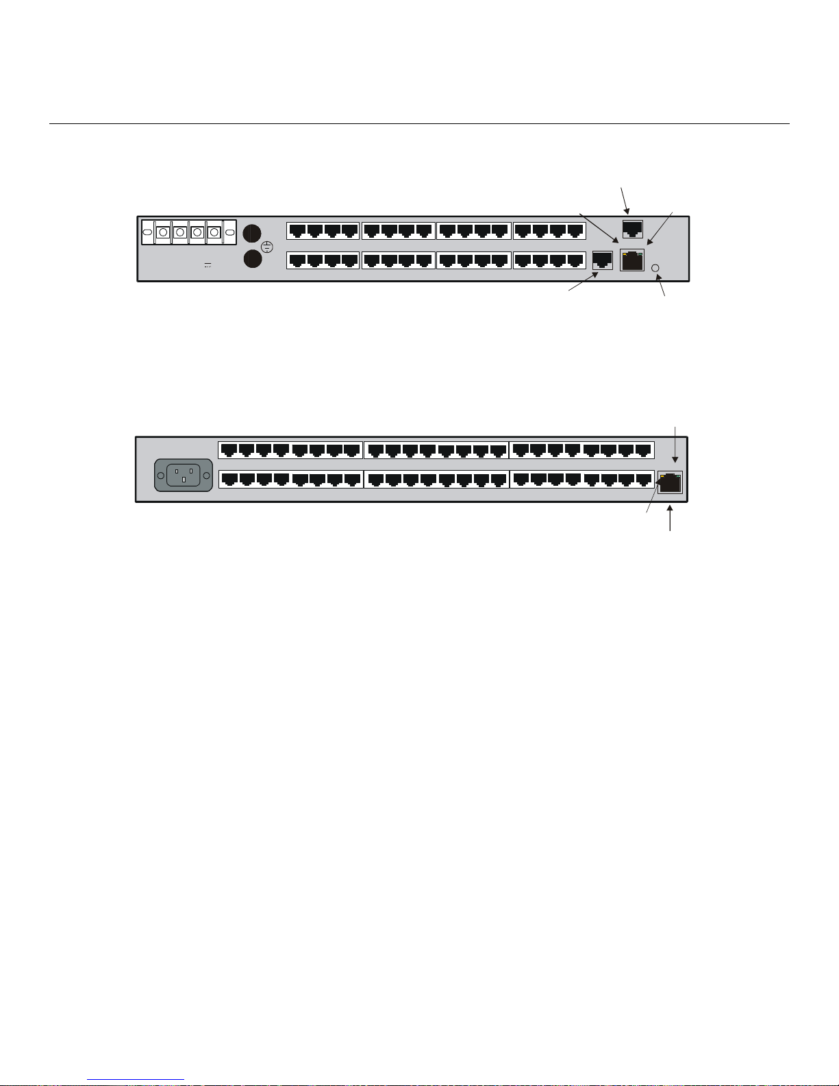
This section explains the rear panel LEDs and shows you a rear view of the various LX-4000 models
(see Figures 5 through 11).
Installing the LX-4000 Series
100-240VAC
1.0A 50/60 Hz
100-240VAC
1.0A 50/60 Hz
1234
5678
DIAG Port (Port 0)
Figure 5 - LX Series 4008 Rear Panel
1 234 5678
1 234 5678
DIAG Port (Port 0)
RCV
10/100
ETHERNET
RCV LINK
DIAG
100 Mbps
LE
Modem Port
RCV
TELCO
LIN E
RCV LINK
DIAG/MGMT
10/100 ETH
10/100
Interface
LIN
100
LINK
100
100
Mbps
LED
Figure 6 - LX Series 4008 with Modem Rear Panel
451-0308 MRV Communications, Inc. www.mrv.com 17
Page 18
Installing the LX-4000 Series
D
K
100-240VAC
1.0A 50/60 Hz
1 23 4 5678
Modem Port
RCV
9101112 131415 16
DIAG
TELCO
LIN E
RCV LINK
10/100 ETHNT
LINK
100
+ -
A
-24/-48/ -6 0 VD C
1.2 MAX
100-240VAC
1.0A 50/60Hz
+ -
DIAG Port (Port 0)
10/100
Interface
100
Mbps
LED
Figure 7 - LX Series 4016 with Modem Rear Panel
RCV
B
1 23 4 5678
9
11 12
10
14 15
13
16
DIAG Port (Port 0)
LIN
10/100
ETHERNET
RCV LIN K
DIAG
100
100 Mbps
LE
Figure 8 - LX Series 4016 DC Version Rear Panel
Modem Port
LINK
RCV
TELCO
LINE
17
1234 5678
1234 5678
18 19
20
21 22 23 2 4
27 28
25 26
9101112 13
9101112 13
29
30 31
14 15
14 15
DIAG
RCV LIN K
100
10/100 ETHNT
32
16
16
18
MRV Communications, Inc. www.mrv.com 451-0308
DIAG Port (Port 0)
10/100
Interface
Figure 9 - LX Series 4032 with Modem Rear Panel
100
Mbps
LED
Page 19
Installing the LX-4000 Series
D
Modem Port
+ -
A
-24/-48/-60 VDC
1.2 MAX
100-240VAC
1.0A 50/60 Hz
+ -
B
25 26 27 28 29
RCV
TELCO
LINE
17 18 19 20 21 22
1 234 5678
23
DIAG Port (Port 0)
24
25 26
9
27
28
11 12
10
30 31
29
13
14 15
32
16
DIAG
RCV LIN K
10 /100 ETH NT
100 Mbps
LE
Figure 10 - LX Series 4032 DC Version with Modem Rear Panel
30 31
34
32
33
35 36 37 38
9 101112 1314151612345678
39
40
42
41
43 44 45
17 18 19 20 21 22 23 24
46 47 48
RCV
10/100
Interface
Figure 11 - LX Serie s 4048 AC Rear Panel
LINK
100
LINK
RCV LINK
10/100 ETH
RCV
The RCV LED is one of two integral LEDs on the 10/100 jack. This yellow LED flashes to indicate
receive activity on the link.
LINK
This green LED defaults to a link good indicator. If the link is present and operating, the LED comes
ON.
100 Mbps
This green LED indicates speed. If the link is 100 Mbps, the LED comes ON. On LX-4048 units, this
LED is on the front of the unit.
Environmental and Installation Considerations
• Unit must be installed in an environment with 5% to 90% humidity, noncondensing, 0° 40° C (32°-104° F).
• Do not choose a location where the unit will be exposed to direct sunlight or subjected to
vibration.
• Do not place an object on the side(s) of the unit that might block airflow through the unit.
451-0308 MRV Communications, Inc. www.mrv.com 19
Page 20
Installing the LX-4000 Series
• The unit may be front, rear, or center mounted.
• There is no mounting difference between the 19” and 23” rack mount ears.
Mounting the Unit into a 19-inch or 23-inch Rack
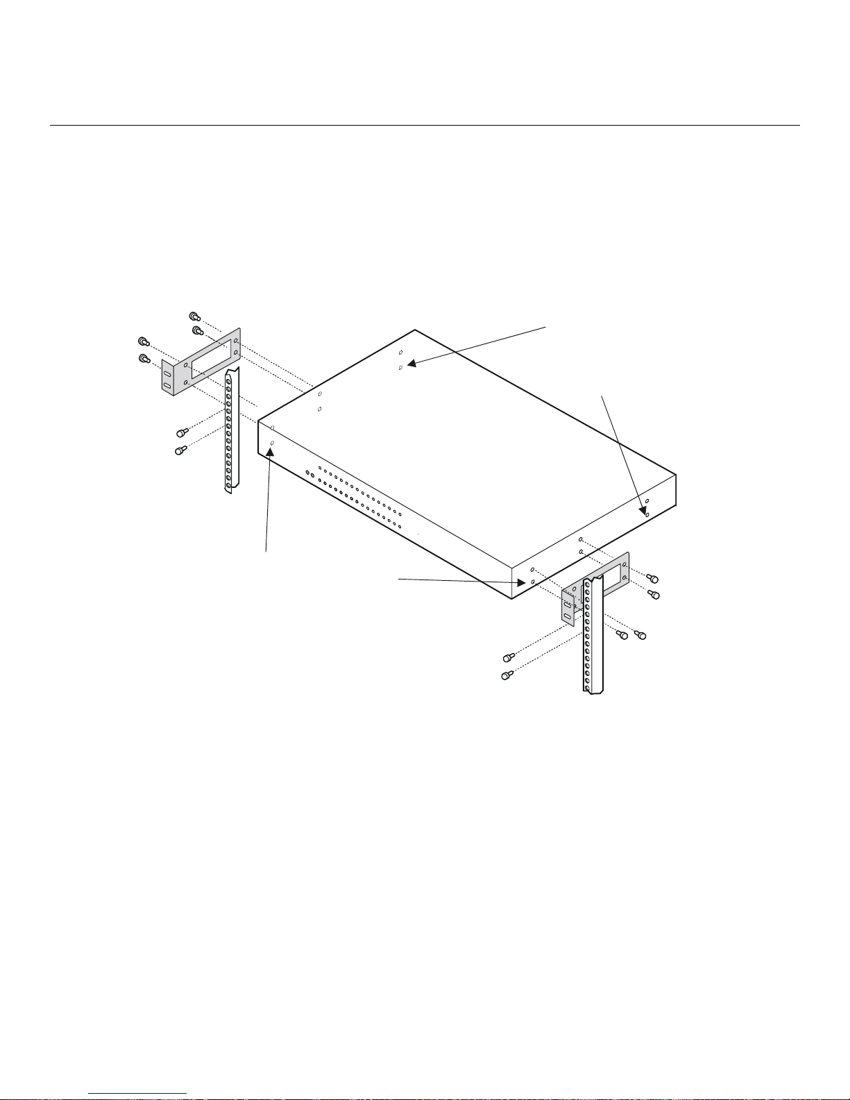
Attach the brackets to the unit, and then mount the unit in the rack. Refer to Figure 12 for further
information.
If you reverse-mount
the unit, remove the rear
and center top and bottom
screws, and insert the
supplied screws through
the rack-mount ears.
The three bottom side screws hold
the cover on the unit. To front-mount
the unit, you must
and center top and bottom screws before
attaching the rack-mount brackets.
Then insert the supplied screws through
the brackets and into the same holes.
remove the front
Cable Connections
This section explains the cable connections for the LX-4000 unit.
Connect the Power Cable
Connect the supplied power cable to the rear of the LX-4000 unit and plug the other end into a 3prong wall outlet.
Connecting the Ethernet Interface
NOTE: This port is set to auto negotiation by default. You can manually configure the port speed
and duplex if you want. Refer to the LX-Series Commands Reference Guide for further
details.
Figure 12 - Mounting an LX-4000 Series in Rack
20
MRV Communications, Inc. www.mrv.com 451-0308
Page 21
Connect a category 3 (CAT 3) cable for 10 Mbps operation, or a category 5 (CAT 5) cable for 10/100
Mbps operation to the 10/100 connector on the rear of the LX-4000 Series (see Figure 5) and the other
end to your network. The LINK LED comes on steady green if the cable is properly connected.
Connect Serial Device Cables
Connect the serial device cables to the 8-pin RJ-45 jacks on the rear of the unit.
NOTE: LX-4000 Series serial ports provide concurrent support for RTS/CTS flow control and
modem control. Refer to Appendix A and Appendix D for further information.
Connecting Your Management Station
Connect the management station to the DIAG port (port 0) using the connector and cable you received
with the LX-4000 unit. Refer to “Connecting to the Diagnostic Port (Port 0)” in Appendix D for more
information on DIAG port connections.
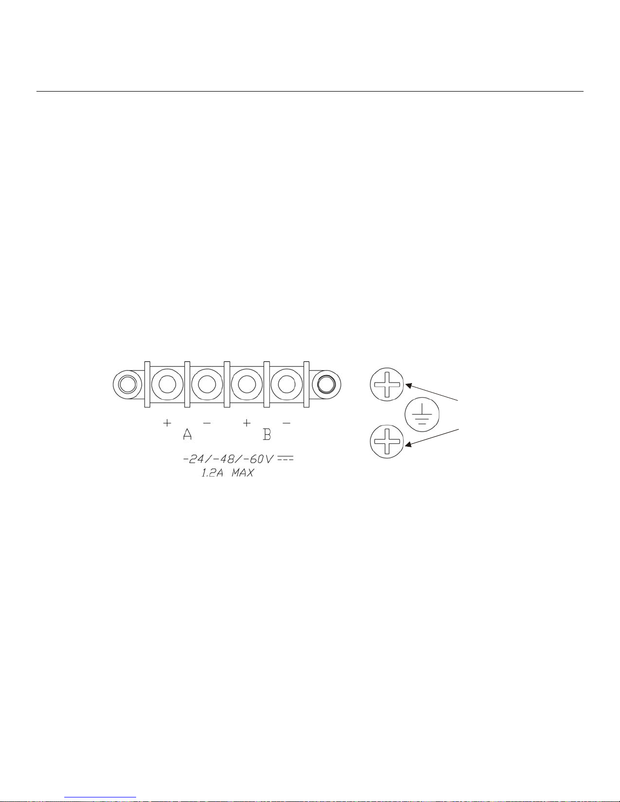
Connecting DC Power
This section describes how to connect power to the DC version of the LX Series 4008, 4016, and 4032.
The LX-4048 model is made in an AC version only.
Installing the LX-4000 Series
#10
Grounding
Lugs
Figure 13 - Connecting DC Power
After you have installed the LX-4000 unit, you can connect the DC power as described in the following
procedure (refer to Figure 13):
1. Connect the LX-4000 to the facility's bonding network (or earth ground), using the points on the
rear panel of the LX-4000. The connection to the facility's bonding network should be made per
local practices, using wire with a minimum conductor size of 18 AWG.
2. Using a ¼-inch nut driver, remove the terminal block nuts.
3. Attach the facility’s “A” feed to the terminal block labeled “A”.
NOTE: Be sure that the -48VDC is connected to the minus side, and the 48VDC return is connected
to the plus side.
4. Attach the facility’s “B” feed to the terminal block labeled “B”.
5. Replace the nuts and tighten them securely.
451-0308 MRV Communications, Inc. www.mrv.com 21
Page 22

Installing the LX-4000 Series
The DC leads should be 22 AWG or larger. They should be terminated with a #5 ring terminal or
larger depending on the wire size used.
NOTE: The LX-4000 will run with only one DC power feed connected. The second input is provided
for redundant system power, which is used in high reliability installations.
6. Attach the clear plastic safety guard to the terminal blocks. (The clear plastic safety guard is provided with the LX-4000 kit.)
Modem Port (Optional)
The modem port is a V.90/K56flex Kbps optional factory installed modem on the LX-4000 Series. The
modem port allows you to dial back from, or dial in to or out of the LX-4000. If the modem is present,
connect your phone line to the modem’s RJ11 connector. If the modem is not installed, the RJ11
connector will not be present on the rear of the unit. In LX-4048 models, the modem port is on the
front of the unit.
The Modem port number is as follows for LX-4000 models:
• LX-4008 - port number 9
• LX-4016 - port number 17
• LX-4032 - port number 33
• LX-4048 - port number 49
At the InReach:0>> prompt, enter the show port async 33 modem command to display a screen
containing the LX-4032 modem port fields.
Powering On
The Power On Self Test (POST) starts when you apply power to the LX-4000 Series unit. The port
status LEDs flicker and the FLT LED remains on while the test is running (this may take only a few
seconds). If the unit passes the POST test, the FLT LED extinguishes, and the OK LED turns green. If
there is a failure, the FLT LED stays on, and the port status LEDs begin flashing an error code. Refer
to Appendix C for an explanation of the codes.
When the POST test is completed, you are presented with two options: [B] Boot System and [L]
Login to System Setup. If you choose neither, the unit boots on its own after eight seconds. If you
type L, a password prompt appears. The default password is access. The Main Menu appears after
you enter the password. The Main Menu allows you to change the boot settings and IP address
assignments. You can review the factory default boot setting by referring to the “ppciboot Factory
Default Settings” on page 50. The system loads the LX-Series software from flash and then loads the
system configuration file.
If the LX boots with default operational parameters, the Quick Configuration menu appears. Refer to
the “System Maintenance” chapter in the LX-Series Configuration Guide for further information on
the Main menu. Refer to “First Time Quick Configuration” on page 25 for further details on the Quick
Configuration menu.
22
MRV Communications, Inc. www.mrv.com 451-0308
Page 23
Once the unit finishes loading the operating system, you can access the unit. At your management
station, access the unit with any terminal emulation software. The terminal settings are 9600 baud,
eight data bits, no parity, one stop bit, Xon/Xoff flow control, autowrap enabled, and terminal type
ANSI. The Login: screen appears.
System Login and Passwords
The following username and passwords are the defaults the first time you use the LX-4000 Series.
• The default login username is InReach (be sure to use a capital I and R). The default
login password is access.
• To enter the superuser mode at the InReach> prompt, enter enable. The default password is
system.
These passwords prevent persons who do not know them from accessing the server. Change the
default passwords to other values as part of your basic server setup. You can use any character or
number in a password. However, backspace, tab, and escape are not supported. Refer to the
“Password Enable” section in the Subscriber chapter of the LX-Series Commands Reference Guide for
information on changing passwords.
Installing the LX-4000 Series
Resetting the Unit
To reset the LX-4000 Series, use a paper clip to momentarily press the reset button, which is behind
the small hole labeled R on the front panel. Refer to Figure 14 for the exact location.
Reset Switch
When the LX-4000 Series enters the RESET state, all front panel LEDs illuminate. When you release
the reset button, the unit begins to execute the Power On Self Test (POST).
If the LX-4000 Series detects an error, the front panel LEDs illuminate to show an error code. This
error sequence is repeated continually until the error is corrected or you power off the unit. During
this time, no data is exchanged over the Ethernet cable or serial ports.
IMPORTANT
Take steps to ensure that the password is not lost or forgotten. If you forget
the password, call Customer Support.
Figure 14 - LX Series RESET Switch Location
If the LX-4000 Series does not detect an error, the unit begins loading software from the internal
flash. Once loaded, the LX-4000 Series resumes normal operations.
451-0308 MRV Communications, Inc. www.mrv.com 23
Page 24

Installing the LX-4000 Series
24
MRV Communications, Inc. www.mrv.com 451-0308
Page 25

Configuring the LX-4000 Series for the First Time
Configuring the LX-4000 Unit for the First Time
You can choose from five options to configure the unit for the first time:
• First Time Configuration Utility - The first time an LX-4000 unit boots up at default
parameters, you are presented with the option to run the Initial Connectivity setup. Enter y and
press <Enter>. Refer to “First Time Quick Configuration” for further details.
• Assign the IP Address via the Network - Refer to “Assigning an IP Address via the Network”
for further details. Use this option if your network is using DHCP, BOOTP, or RARP.
• Setting the IP Address Manually - Refer to “Manually Setting the IP Address Via the CLI”.
• Creating and Loading a Default Configuration File - Refer to “Applying Default
Configurations to Other Units” in the LX-Series Configuration Guide.
• Configuring the LX-4000 Manually via the CLI - Refer to “Upgrading Software with the
ppciboot Main Menu” in the LX-Series Configuration Guide.
Chapter 3
First Time Quick Configuration
NOTE: The first time quick configuration runs only on the DIAG port (port 0) on all models when
booting from default parameters. The DIAG port (port 0) of the LX-4008, LX-4016, and LX4032 is on the rear of the unit. The LX-4048 DIAG port (port 0) is on the front of the unit.
NOTE: Display problems may occur during bootup when you attach a terminal to the DIAG port
(port 0) and the display setup is configured to Smooth-2 Scroll. To avoid this, change the
scroll setting to Jump Scroll.
Use the following procedure to configure your LX-4000 unit for the first time.
1. Plug in the terminal at the DIAG port (port 0 - port values are 9600 bps, eight data bits, one stop
bit, no parity, and Xon/Xoff flow control). The Main Menu appears.
451-0308 MRV Communications, Inc. www.mrv.com 25
Page 26

Configuring the LX-4000 Series for the First Time
2. Press b to boot the LX-4000 unit. The setup takes a minute or two. The The unit has loaded
to factory defaults, would you like to run Initial Connectivity Setup? y/n
message appears.
3. Press y (yes) and press Enter. The “Enter your superuser password” message appears, followed by the Superuser Password prompt.
4. Enter superuser password system. The Quick Configuration menu appears:
Quick Configuration menu
1 Unit IP address
2 Subnet mask
3 Default Gateway
4 Domain Name Server
5 Domain Name Suffix
6 Cluster Secret
7 Superuser Password
8 Exit and Save
Enter your choice:
5. Press the number corresponding to the parameter you want to set.
6. Enter the appropriate information and press <Enter> to return to the Quick Configuration menu.
Once you enter a parameter value, a data entry line specific to that parameter appears on the
Quick Configuration menu.
7. Continue in this way through the menu, configuring as many parameters as you want. You are
not required to configure all parameters.
NOTE: You should change the Superuser Password, since this is the first time you are configuring
the LX-4000 unit (the default password is system). The login username and password are
case-sensitive.
26
MRV Communications, Inc. www.mrv.com 451-0308
Page 27

Configuring the LX-4000 Series for the First Time
8. Press 8 (Exit and Save) to save your changes. The “Is this information correct?” mes-
sage appears.
CONFIGURATION SUMMARY
1 Unit IP address 10.80.1.5
2 Subnet mask 255.0.0.0
3 Default Gateway
4 Domain Name Server
5 Domain Name Suffix
6 Cluster Secret Configured
7 Superuser Password Not Changed
8 Exit and Save
Is this information correct? (y/n) :
9. Press y (yes) and press <Enter>. The Save this information to flash? message appears.
10. Press y (yes) and press <Enter>. The information is saved to flash.
11. Press <Enter> several times to display the Login: prompt.
12. Enter your login name. The default is InReach.
13. Enter your password. The default is access. You can now use the LX-4000 unit.
Completing the First Time Configuration
Once configured, the system stores the configuration in a file called Config.prm by default. From
here you can continue configuring the unit via the CLI, Telnet, SSH, or by using the web browser.
• To use the CLI, refer to Figure 15 on page 36 for the CLI tree structure and to the LX-Series
Commands Reference Guide for information on specific commands.
• To use Telnet, refer to “Connecting to the LX-4000 Series via Telnet or SSH” on page 34.
• To use the web browser, refer to “Accessing and Configuring the Graphical User Interface (GUI)”
on page 28.
Assigning an IP Address via the Network
If you are running DHCP, BOOTP, or RARP the LX-4000 obtains its own IP information
automatically while it boots.
Once the unit has been assigned an IP address from your network, you can configure the unit.
• To use the CLI, refer to Figure 15 on page 36 for the CLI tree structure and to the LX-Series
Commands Reference Guide for information on specific commands.
• To use Telnet, refer to “Connecting to the LX-4000 Series via Telnet or SSH” on page 34.
• To use the web browser, refer to “Accessing and Configuring the Graphical User Interface (GUI)”
on page 28.
451-0308 MRV Communications, Inc. www.mrv.com 27
Page 28

Configuring the LX-4000 Series for the First Time
Manually Setting the IP Address Via the CLI
If the unit boots up with or without an IP address from the network, you can change the addressing
via the CLI.
Use the following procedure to change the IP address information as needed:
1. Connect the terminal to the DIAG port (port 0 - port values are 9600 bps, eight data bits, one stop
bit, no parity, and Xon/Xoff flow control).
2. Press <Enter> several times to display the Login: prompt.
3. Enter your login name. The default is InReach.
4. Enter your password. The default is access. The InReach:0> user prompt appears.
5. Enter enable and press <Enter>. The Password: prompt appears.
6. Enter the default system and press <Enter>. The InReach:0>> superuser prompt appears.
7. Enter config and press <Enter>. The Config:0>> prompt appears.
8. Enter interface 1 and press <Enter>. The Intf 1-1:0>> prompt appears.
9. Enter address ip_address mask network_mask and press <Enter>. The Intf 1-1:0>>
prompt reappears.
10. Enter broadcast broadcast_address and press <Enter>. The Intf 1-1:0>> prompt reappears.
11. Enter exit and press <Enter>. The Config:0>> prompt appears.
12. Enter gateway gateway_address and press <Enter>. The Config:0>> prompt reappears.
13. Enter exit and press <Enter>. The InReach:0>> superuser prompt appears.
14. Enter save config flash to save your changes.
Accessing and Configuring the Graphical User Interface (GUI)
IMPORTANT
If your browser is connected to an LX running an older software version, you must close
the browser completely and clear the cache before connecting your browser to an LX running a
more recent software version. This is because the Java saves the applet to your PC. If you fail to
close the browser completely, the browser will use the old applet when you connect to the
LX running a later software version, and therefore some features will be missing from the GUI
windows.
This section describes how to access and configure the LX via the GUI. To perform this procedure,
you need a PC with Java Runtime Environment (JRE) 1.4.2 or later installed.
NOTE: For optimum GUI performance, MRV recommends that your PC run at 500 MHz or better.
The minimum requirement for desktop color settings is 256.
28
MRV Communications, Inc. www.mrv.com 451-0308
Page 29
Configuring the LX-4000 Series for the First Time
The GUI has two modes: Configuration and Menu. The one you can access depends on what privileges
the administrator has given you.
To access the GUI, do the following:
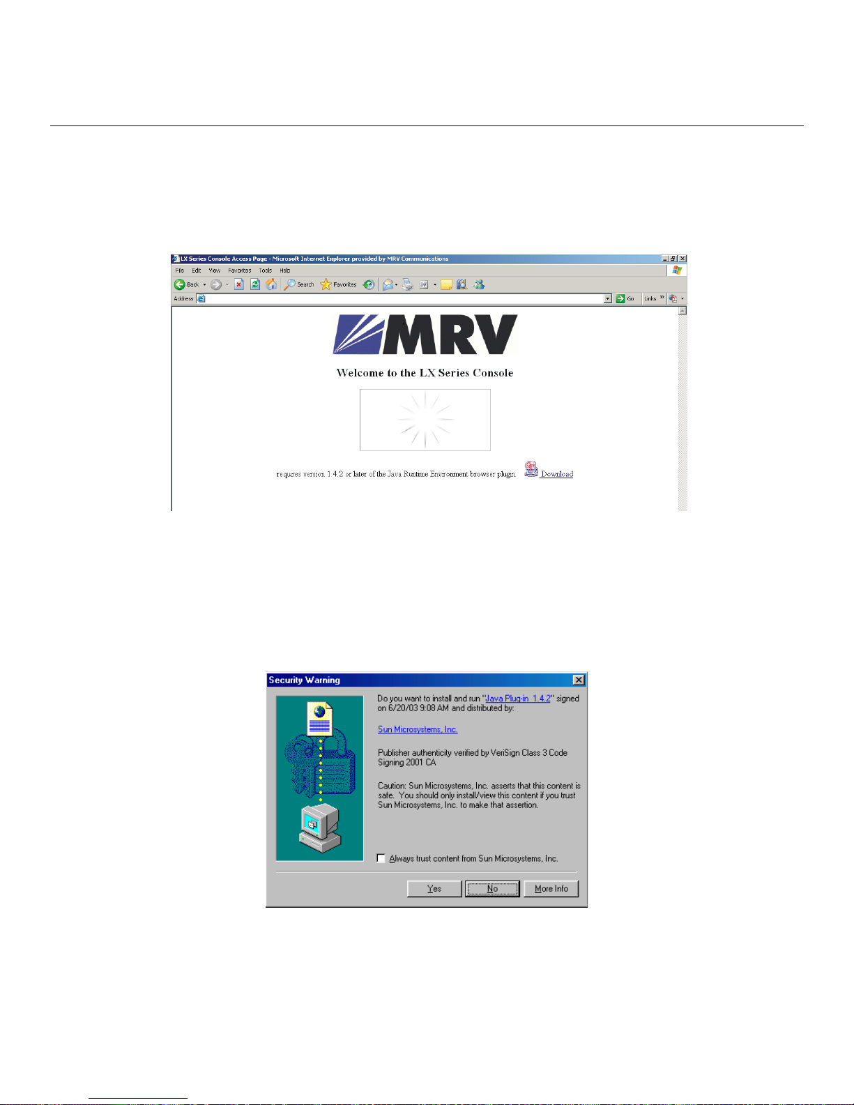
1. At your browser, type the IP address of your LX-4000 unit. The LX Series Console page appears.
NOTE: Make sure that your PC has access to the World Wide Web. You may need to download the
latest release of the Java plug in to your PC. This download is performed automatically if
the GUI sees that the plugin version is out of date, or not available at all. If for some reason
your PC does not download the Java plug-in automatically, click on the Download link and
install the software manually from the http://java.sun.com web site.
2. If you need to download Java, the following window appears automatically.
3. Click Yes. The plugin is downloaded and then the installation begins. A Java Runtime Environ-
ment window appears after about two minutes.
NOTE: Depending on the speed of your PC, this may take several minutes.
451-0308 MRV Communications, Inc. www.mrv.com 29
Page 30
Configuring the LX-4000 Series for the First Time
4. Follow the defaults to the end of the install.
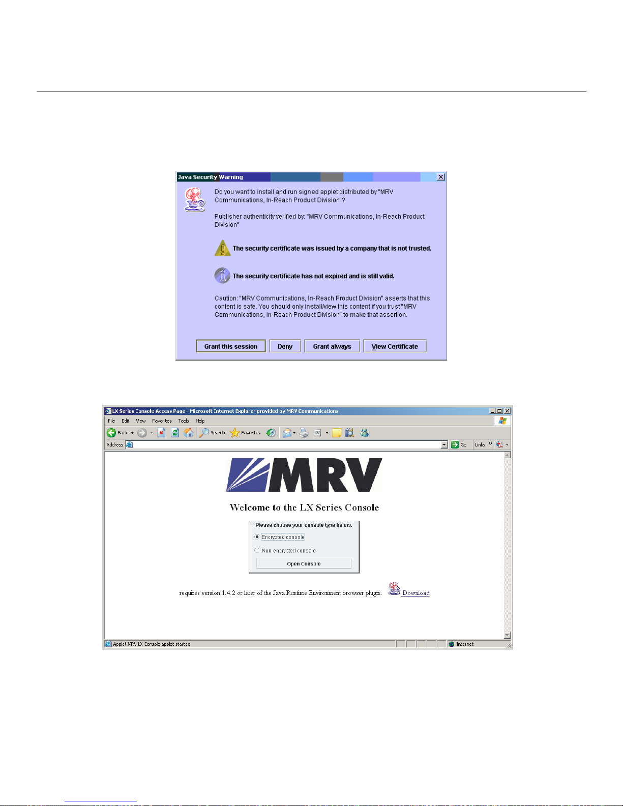
5. When your browser connects to the LX, the Java Security Warning window appears.
NOTE: Your Java Security Warning window may vary, depending on your PC operating system.
6. Click on Grant this session. The Java Security Warning window closes. The LX Series Console
page reappears, now with the console selection visible.
7. Choosing Encrypted Console means the GUI will run slower, but with security. Choosing Non-
Encrypted Console means the GUI will run faster, but without security.
8. Select Encrypted or Non-Encrypted and then select Open Console. A login window
appears.
30
MRV Communications, Inc. www.mrv.com 451-0308
Page 31
9. Enter your Username and Password, and click Login.
NOTE: By default, authentication is done against the LX local user database. To start, use the
known username InReach and password access.
When you login, the next screen that appears depends on which mode you are authorized to configure
and monitor. Refer to “Web Configure Mode” on page 31 or “Web Access Mode” on page 32, depending
on which mode you can access.
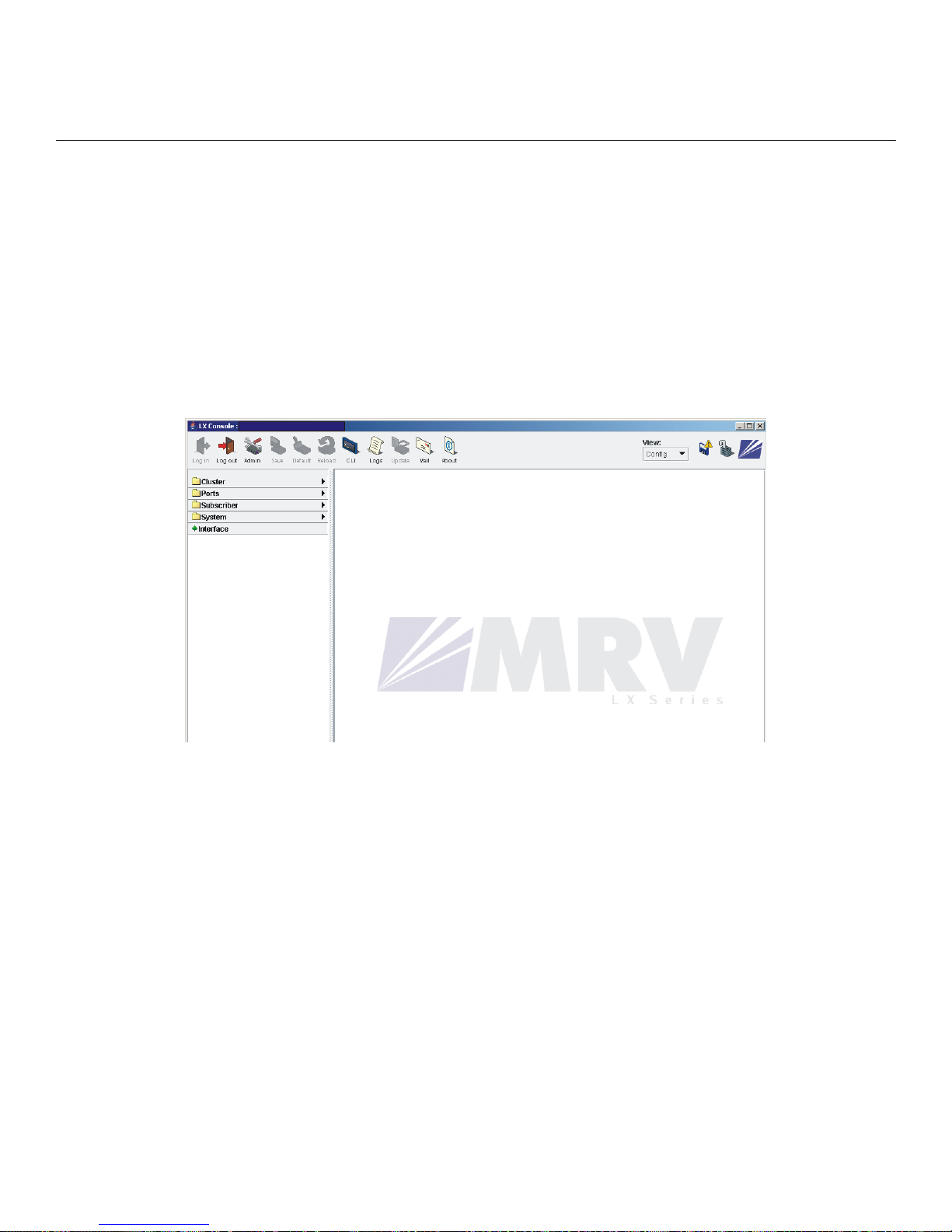
Web Configure Mode
If you are authorized to access the Web Configure Mode, do the following:
1. If you log in as a user, the following window appears.
Configuring the LX-4000 Series for the First Time
2. To log in as a superuser, click the Admin button on the tool bar and log in with the default Supe-
ruser password system. You can now configure the unit via the GUI.
451-0308 MRV Communications, Inc. www.mrv.com 31
Page 32
Configuring the LX-4000 Series for the First Time
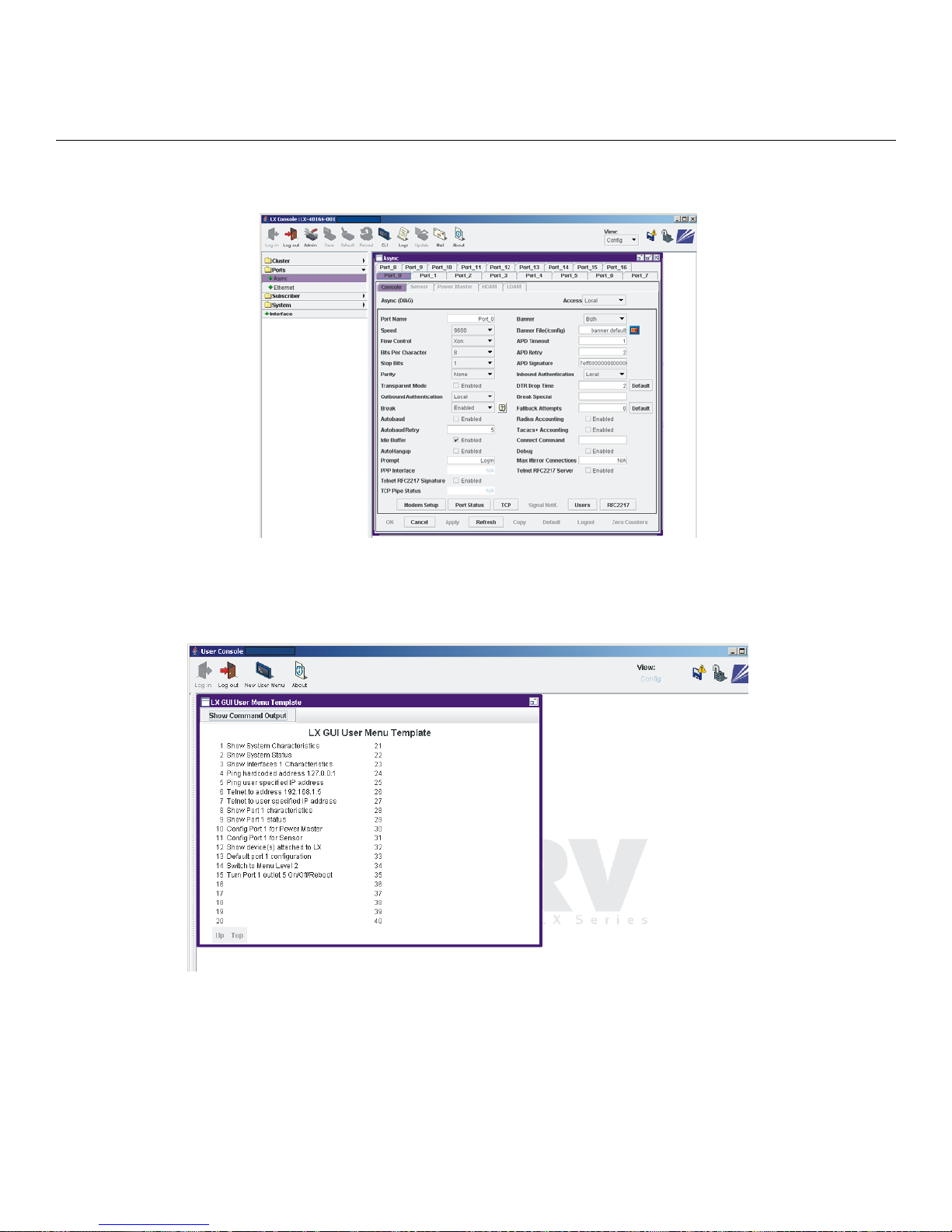
3. Click on the menu items on the left side of the window. For example, selecting Port s: Async opens
the Async ports window.
Web Access Mode
If you have Web Access Mode, your pre-configured menu screen appears when you login. Click on the
various menu items on the left side of the window to perform preconfigured menu option tasks.
Menu/Config Mode
When you have both Menu and Config modes, your initial login presents the menu. Then select View:
Config to open the Config Mode window. After completing your configuration, click on the Save
button on the toolbar to save your changes.
32
MRV Communications, Inc. www.mrv.com 451-0308
Page 33
GUI EZ Configuration
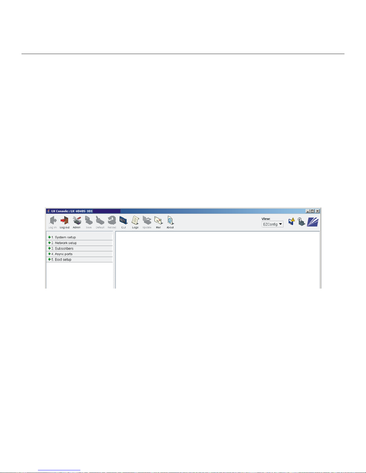
The GUI EZConfig is an ease-of-use configuration tool for basic LX configuration
after initial installation. More experienced users with more complex networks to
configure should use the standard GUI, rather than the EZConfig GUI.
Launching the EZConfig GUI
To access the EZConfig GUI windows:
1. Open your browser.
2. Select Encrypted console or Non-encrypted console and click Open Console.
3. Enter a valid username and password and click Login. The top-level LX Console window appears.
4. Login as superuser (the default is system).
5. In the top right side of the window, select the down arrow to the right of View: Config.
6. Choose EZConfig from the pull-down menu. The five-option menu appears as shown in the following win-
dow.
Configuring the LX-4000 Series for the First Time
Select each of the following menu options to open a specific window for quick configuration.
1. System setup
2. Network setup
3. Subscribers
4. Async Port
5. Boot setup
Follow the menu and the accompanying help text to configure the LX unit.
451-0308 MRV Communications, Inc. www.mrv.com 33
Page 34

Configuring the LX-4000 Series for the First Time
Software Upgrades
To upgrade software using the ppciboot menu, refer to “Upgrading Software with the ppciboot Main
Menu” in the LX-Series Configuration Guide. To upgrade software using the CLI, refer to “Upgrading
Software and ppciboot with the Command Line Interface” in the same manual.
IP Configuration Menu
For details on using the IP Configuration Menu, refer to “Using the IP Configuration Menu” in the
LX-Series Configuration Guide.
Booting from Defaults
For information on how to boot your unit from defaults, refer to “Booting from Defaults” in the LXSeries Configuration Guide.
Accessing and Configuring Additional Features
The following sections describe additional LX-4000 features you can access and configure.
Connecting to the LX-4000 Series via Telnet or SSH
Telnet Directly into the Communication Server
NOTE: The default telnet port is 23. The default SSH port is 22.
1. Telnet to the unit from your machine.
2. Enter your subscriber login name, then your password.
3. If you entered the password correctly, the user> prompt is displayed.
Connecting to a Serial Port
NOTE: Devices connected to serial ports 1-32 on the LX-4032 are assigned telnet port numbers
2100-5200 by default. For example:
• Port 1 = 2100
• Port 2 = 2200
• Port 3 = 2300
NOTE: The corresponding SSH port numbers are 2122-5222. For example:
• Port 1 = 2122
• Port 2 = 2222
• Port 3 = 2322
You can gain telnet/ssh access to a serial device by using the LX IP address and default port number
of that serial port.
Changing the Telnet Port
To change the interface telnet port number, use the following commands:
InReach> enable
34
MRV Communications, Inc. www.mrv.com 451-0308
Page 35

Configuring the LX-4000 Series for the First Time
Password> system
InReach>> config
Config:0>> interface 1
Intf 1-1:0>> telnet port #
NOTE: If you change the port number, be sure not to use a socket number assigned to another
application or daemon.
Accessing from a Terminal Attached to an LX-4000 Series Serial Port
Use the following procedure to access the command line interface port from a dumb terminal attached
to an LX Series serial port, which is set for access local, or dynamic:
1. Hit the return key several times to autobaud (if autobaud is enabled) the port and get the Login:
prompt.
2. Enter your login name. The default is InReach.
3. Enter your password. The default is access.
Additional Considerations
Other considerations include the following:
• Setting up users
• Authentication/Security
• Configuring modem settings
For further information on these issues, refer to the LX-Series Commands Reference Guide, and to the
Support area of the MRV website at www.mrv.com.
451-0308 MRV Communications, Inc. www.mrv.com 35
Page 36
Configuring the LX-4000 Series for the First Time
Command Line Interface (CLI) Tree Structure
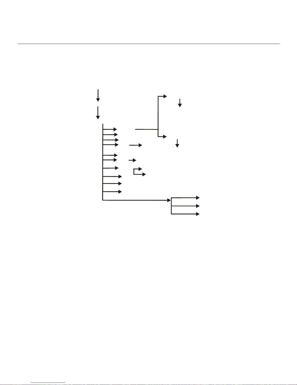
The command line interface structure is designed to be as intuitive as possible. Refer to “Navigating
the LX Command Line Interface (CLI)” in the LX-Series Commands Reference Guide for detailed
information on the menu tree modes. See Figure 15 for the CLI menu structure.
User
Enter “enable” command and
login to Superuser command mode
Superuser
Cconfiguration
Configuration
Nnotification
Ssnmp
Pport ethernet
Pport async
Ssubscribe r
Mmenu
Iinterface
Aauthentication
cluster
hdam
trigger-action
Notification
SNMP
Ethernet
Mmodem
Async
Subscriber
Oopen
Menu
Interface
AAA
Cluster Config
HDAM
Trigger-Action
Modem
Menu Editing
Ibroadcast
group
Broadcast Group
Pppp
PPP
Service Profile
Protocol Command
See Note (below)
User Service
User Information
Maction name
Trule name
Mtrigg e r n am e
Modes --
Action
Rule
Trigger
Note: The Protocol Command Modes include Async, Localsyslog,
Remotesyslog, SMTP, SNPP, TAP, and WEB.
Figure 15 - Basic Menu Structure
Additional Considerations for an Internet Environment
If you plan to use the unit in an Internet environment, you must define addressing and identification
characteristics to enable Internet hosts to recognize the unit as a member of the network. Using
ppciboot, an LX-Series unit can be configured to obtain an IP address and other parameter values
from the network when the unit boots.
Autobauding Feature
Autobaud is disabled on all ports. The administrator can enable autobaud on a per-port basis, except
for the DIAG port (port 0). Default settings for the DIAG port (port 0) are 9600/8/None/1.
Reinitializing/Powering Off the Unit
To reinitialize the unit, enter the following command from the superuser mode:
reload
To power off the unit, disconnect the power cord.
36
MRV Communications, Inc. www.mrv.com 451-0308
Page 37

The LX-4000 Series offers extended capabilities beyond traditional RS-232 communication uses. For
example, a port with specialized hardware attached can be configured to monitor temperature and
humidity remotely. The following sections present some of these capabilities.
Sensor (Temperature/Humidity) Ports
NOTE: Refer to Appendix A for Temperature/Humidity sensor technical specifications.
You can configure ports to act as temperature and humidity monitors when connected to an In-Reach
Temperature/Humidity Sensor. The Temperature/Humidity Sensor provides an accurate
measurement of the temperature/humidity in the area in which your LX Series unit is placed.
The following section explains how to connect and install the sensor.
Connecting the Temperature/Humidity Sensor
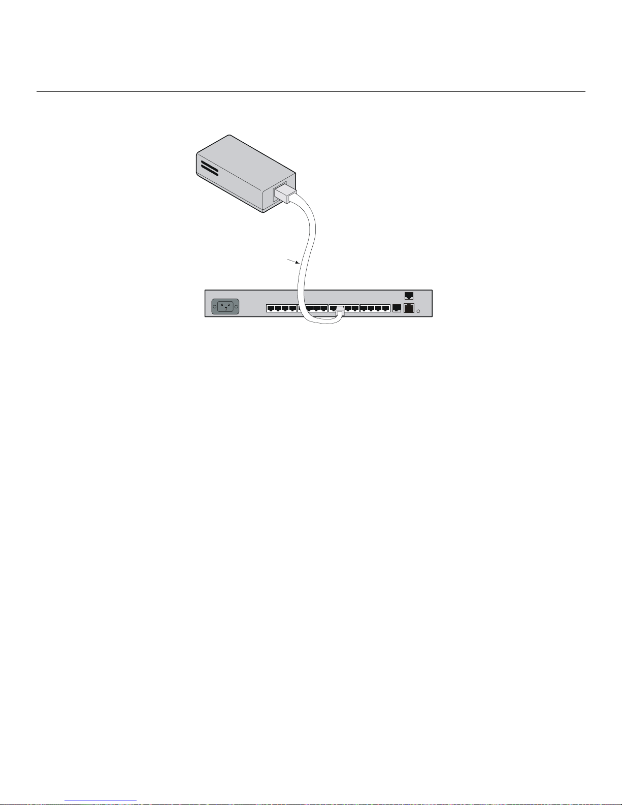
A 10’ Male RJ-45 to Male RJ-45 straight-through cable (P/N MX-151-3027) connects the temperature/
humidity sensor to an LX-4000 async port. The LX unit can be configured to support the sensor on
any async port other than the DIAG port (port 0).
Chapter 4
Alternative Port Capabilities
To connect the sensor:
1. Connect one end of the RJ-45 double-ended straight through cable to the temperature/humidity
sensor. The maximum length of this cable is 50 feet.
451-0308 MRV Communications, Inc. www.mrv.com 37
Page 38
Alternative Port Capabilities
2. Connect the other end to any port you have configured as a sensor port.
RJ45 Double-Ended
Straight-Through Cable
Figure 16 - Connecting the Temperature/Humidity Sensor
You must change the port’s “access” to “sensor” before performing any monitoring. Use the
following command, in the Async Port Configure Mode, to configure asynchronous port 4 as a
Sensor Port:
Async 4-4:0>>access sensor
Once the sensor is enabled, you can check the temperature with the following command:
InReach:0>> show port async 4 status
3. You can also monitor the temperature/humidity remotely through the LX CLI. Refer to the LXSeries Commands Reference Guide for a detailed explanation of the commands used to configure
and view your temperature/humidity sensor through the CLI interface.
5250 Power Management
100-240VAC
1.0A 50/60Hz
12 34 5678
910111213141516
15
33 34
TELCO
LINE
RCV L INK
100
DIAG
10/100 ETHNT
The 5250 Power Control Series family of products provides easy, practical, and secure solutions for
power distribution, power management and load-measurement for data centers and remote sites.
5250 Power Control Series products are available in a variety of models for 100-120VAC up to 30A,
and for 230VAC up to 16A (Continental Europe). A 5250 Series offers individual remote control over
the power on/off status to a maximum of 32 devices.
See the Technical Specifications Appendix for more information about available 5250 Power Control
Series models.
The following section explains how to connect and install the 5250.
38
MRV Communications, Inc. www.mrv.com 451-0308
Page 39
Connecting the 5250
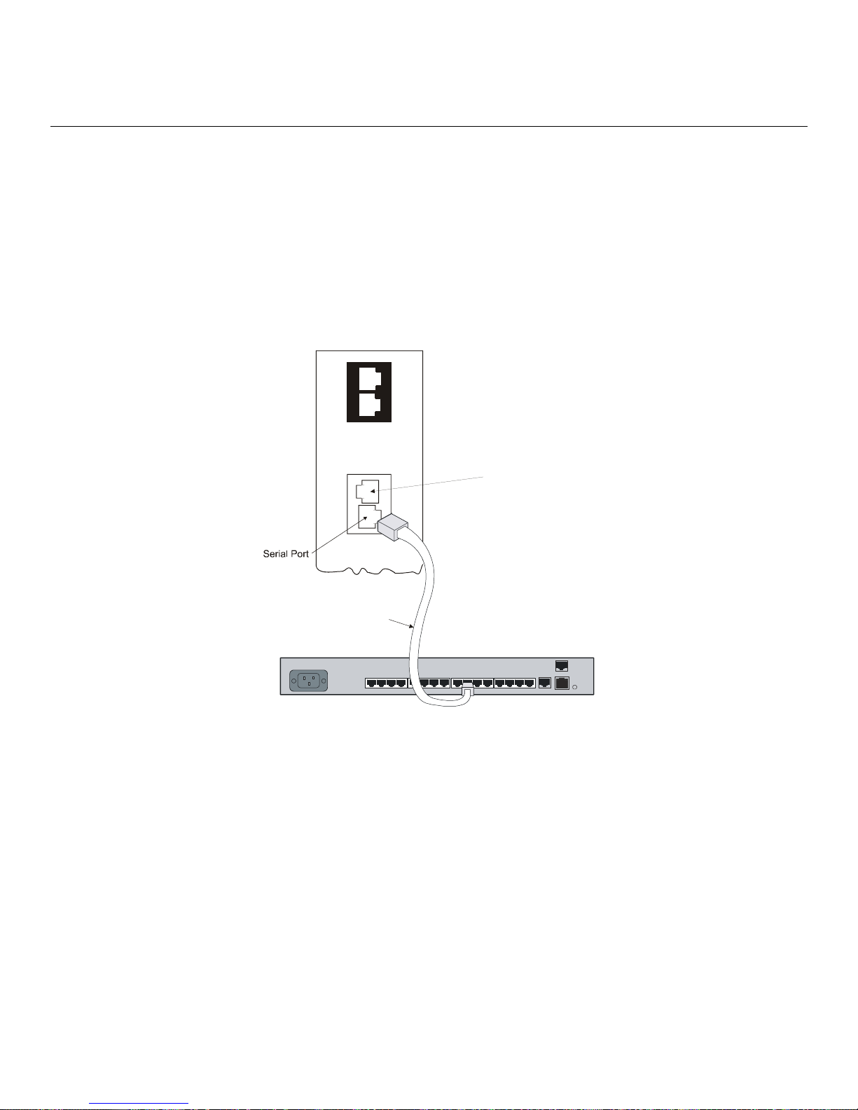
The 5250 Series is equipped with a single RJ45 RS-232 serial port for attachment to the LX serial
port using the supplied RJ45 to RJ45 crossover cable and RJ45 to DB9F serial port adapter as
required. See the Technical Specifications in Getting Started with the 5250 Power Control Series for
more information about the RS-232 serial port.
To connect the 5250:
1. Connect one end of the standard RJ-45 double-ended crossover cable to the serial port of the 5250.
2. Connect the other end to any LX-Series port you have configured as a power management port.
Alternative Port Capabilities
T/H 1
Top of
vertical 5250
Power Control
Series unit
T/H 2
NET
Connect a Network
cable to a hub or switch
only when you want to
upload firmware.
SER
RJ-45 Double-Ended
Crossover Cable
LX-4000
100-240VAC
1.0A 50/60Hz
12 34 5678
91011 121314 15
TELCO
LINE
RCV LINK
16
100
DIAG
10/100ETHNT
Figure 17 - Connecting the 5250
You must change the port’s “access” to “power model ir5250” before performing any control
and monitoring. Use the following command, in the Async Port Configure Mode, to configure
asynchronous port 1 as a 5250 port:
Async 1-1:0>>access power model ir5250
After the 5250 is enabled, you can check its status with the following command:
InReach:0>> show port async 1 status
3. You can also control and monitor the 5250 remotely through the LX CLI. See the LX-Series Commands
Reference Guide for a detailed explanation of the commands used to configure and view your 5250
through the CLI interface. See Chapter 3 for details on how to access the GUI interface.
451-0308 MRV Communications, Inc. www.mrv.com 39
Page 40
Alternative Port Capabilities
5150 Power Strip Management
The 5150 Series family of products provides easy, practical, and secure solutions for power
distribution, power management and load-measurement for remote internetworking equipment and
branch AC circuits.
5150 Series products are available in 8-outlet and 16-outlet configurations for 100-120VAC up to 30A,
and for 230VAC up to 16A (Continental Europe). An 5150 Series offers individual remote control over
the power on/off status to a maximum of 16 devices.
The following section explains how to connect and install the 5150.
Connecting the 5150
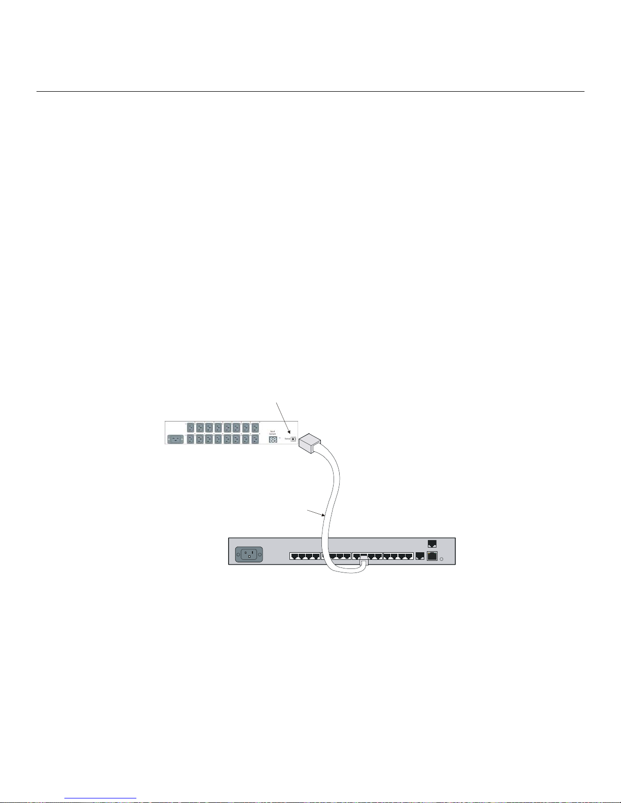
The 5150 Series is equipped with a single RJ45 RS-232 serial port for attachment to a PC or
networked terminal server using the supplied RJ45 to RJ45 crossover cable and RJ45 to DB9F serial
port adapter as required. See the Technical Specifications in Getting Started with the MRV
Communications 5150 Power Control Series for more information on the RS-232 serial port.
To connect the 5150:
1. Connect one end of the standard RJ-45 double-ended crossover cable to the serial port of the 5150.
2. Connect the other end to any port you have configured as a power management port.
Serial Port
IR-5150
RJ-45 Double-Ended
Crossover C able
LX-4000
100-240VAC
1.0A 50/60Hz
1234 5678
91011 121314 15
TELCO
LINE
RCV LINK
16
100
DIAG
10/100ETHNT
Figure 18 - Connecting the 5150
You must change the port’s “access” to “power model ir5150” before performing any control and
monitoring. Use the following command, in the Async Port Configure Mode, to configure
asynchronous port 1 as an 5150 port:
Async 1-1:0>>access power model ir5150
Once the 5150 is enabled, you can check its status with the following command:
InReach:0>> show port async 1 status
40
MRV Communications, Inc. www.mrv.com 451-0308
Page 41
3. You can also control and monitor the 5150 remotely through the LX CLI. Refer to the LX-Series
Commands Reference Guide for a detailed explanation of the commands used to configure and
view your 5150 through the CLI interface.
4800 Power Strip Management
The 4800 -48 VDC Series family of products provides easy, practical, and secure solutions for power
distribution, power management and load-measurement for remote internetworking equipment and
branch AC circuits.
4800 Series products are available in a 4-outlet configuration. An 4800 Series offers individual
remote control over the power on/off status to a maximum of four DC powered devices. The 4800
supports -48 VDC up to 70A.
The following section explains how to connect and install the 4800.
Connecting the 4800
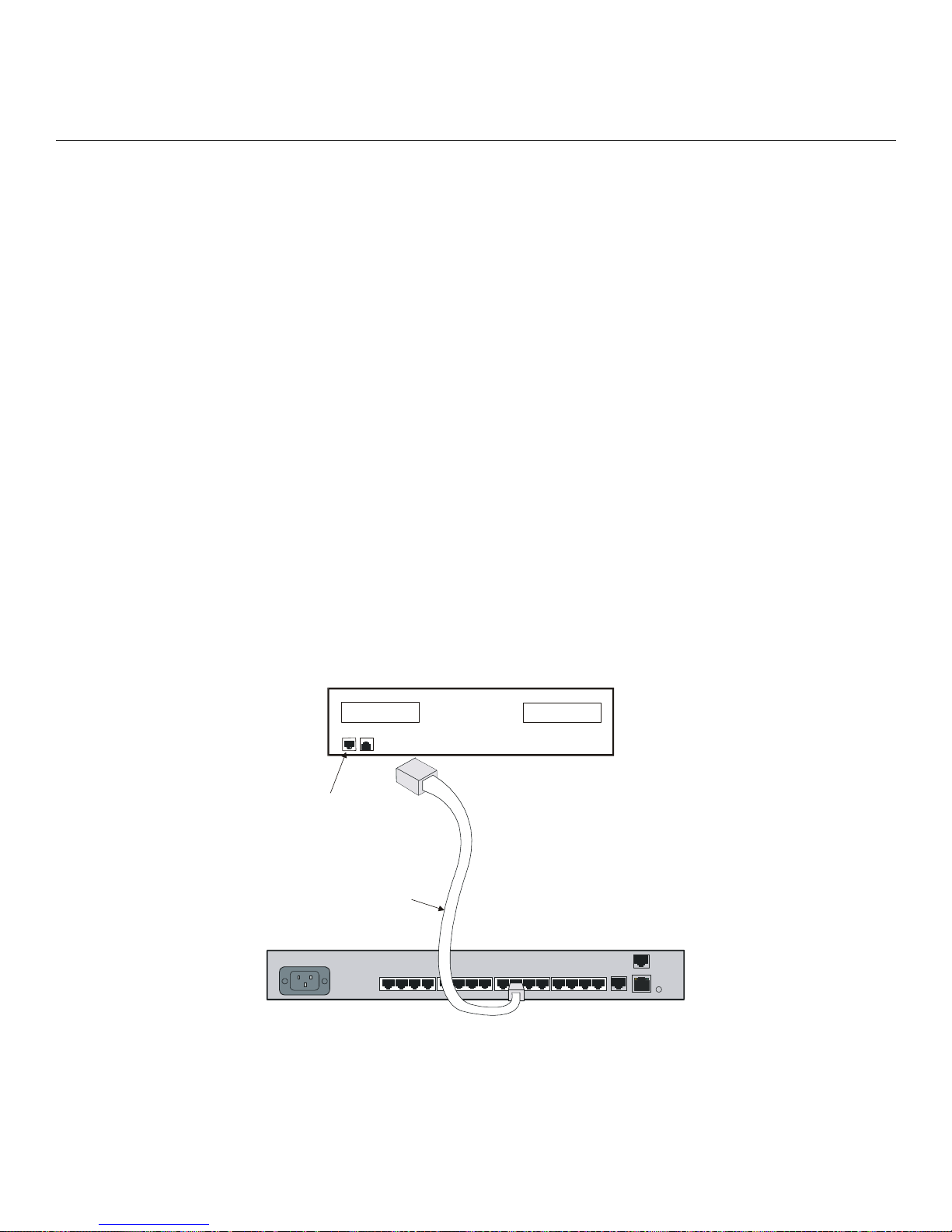
The 4800 Series is equipped with a single RJ45 RS-232 serial port for attachment to a PC or
networked terminal server using the supplied RJ45 to RJ45 crossover cable and RJ45 to DB9F serial
port adapter as required. See the Technical Specifications in Getting Started with the MRV
Communications 4800 Power Control Series for more information on the RS-232 serial port.
Alternative Port Capabilities
To connect the 4800:
1. Connect one end of the standard RJ-45 double-ended crossover cable to the serial port of the 4800.
2. Connect the other end to any LX port you have configured as a power management port.
IR-4800
Serial Port
RJ-45 Double-Ended
Crossover Cable
LX-4000
100-240VAC
1.0A 50/60 Hz
1234 5678
91011 121314 15
TELCO
LINE
RCV LINK
16
100
DIAG
10/100 ETHNT
451-0308 MRV Communications, Inc. www.mrv.com 41
Figure 19 - Connecting the 4800
Page 42

Alternative Port Capabilities
You must change the port’s “access” to “power model ir4800” before performing any control and
monitoring operations. Use the following command, in the Async Port Configure Mode, to
configure asynchronous port 10 as a 4800 port:
Async 1-10:0>>access power model ir4800
Once the 4800 is enabled, you can check its status with the following command:
InReach:0>> show port async 10 status
3. You can also control and monitor the 4800 remotely through the LX CLI. Refer to the LX-Series
Commands Reference Guide for a detailed explanation of the commands used to configure and
view your 4800 through the CLI interface.
Using LX Ports as Alarm Inputs and Control Outputs
The LX-Series can be configured to provide two low voltage/low current outputs per port which can be
used to control remote devices. Using the DTR and RTS signals, these are designated Control
Outputs. They can be used to control external equipment, or they may be used as the controlling
voltage for Alarm Inputs circuits.
The LX-Series can be configured to provide two signal monitor inputs per port using the DSR and
CTS signal to provide a remote device monitoring capability. These are designated Alarm Inputs. The
following sections describe the use of these signals in greater detail.
Some common terms are:
• Alarm Inputs - LX-Series port input signals DSR and CTS used in conjunction with the SignalNotice software feature to monitor real world events.
• Alarm Points - High impedance, low current, isolated inputs available in the MRV Corporation
IR-7104 product.
• Control Outputs - LX-Series port output signals DTR and RTS managed with the Access Control
software commands that could be used to control external equipment or provide a controlling
voltage for Alarm Inputs.
• Control Relays - True SPDT (Single Pole Double Throw) “Form C” Relay contact points
available in the MRV Corporation IR-7104 product.
Alarm Inputs Setup and Usage
The LX-Series can be configured to provide two Alarm Inputs per port using the DSR and CTS
signals. These are enabled with the Signal-Notice feature. Signal-Notice utilizes sets of Trigger-
Action-Rule commands to detect contact closure/opens. The contacts you are monitoring may be
located within your facility, for example doors alarms, window alarms or fluid level sensors. The
contacts may also be contained within your equipment you wish to monitor, for example equipment
fault alarms, temperature alarms and other error condition signals. The signaling device may be a
simple electro-mechanical device such as a switch, a magnetic contact or a relay. The signaling device
may also be electrical such as an opto-isolator, a CMOS driver or a transistor circuit. Typical circuits
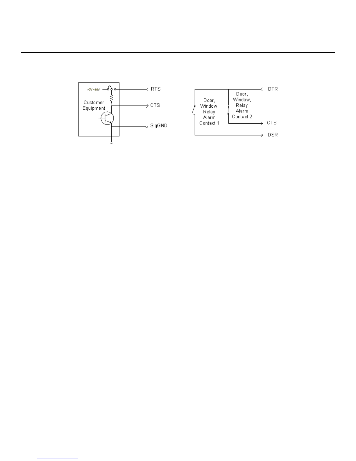
are illustrated in Figure 20.
42
MRV Communications, Inc. www.mrv.com 451-0308
Page 43
Alternative Port Capabilities
Alarm Inputs use the LX-Series input circuits (DSR and CTS) to detect level transitions. These input
circuits sit at the 0V level when left unconnected and can accept a voltage input in the range of ±10V.
Figure 20 - Typical Alarm Inputs Connections
An external voltage within the range of ±10V is required in order for a change to be detected when the
contact opens or closes. Typically, an LX-Series Control Output is used to provide the controlling
voltage for the Alarm Inputs, but it is not required. An external voltage could be used as long as it is
within both the ±10V limits and the limits of the contacts or semiconductor used in the circuit. A
common Signal Ground is required. Refer to Figure 20 for typical implementations.
Important design issues to remember are:
• Electro-mechanical contacts must be rated up to 10V and 3.5mA.
• The inputs present a nominal 5K Ohm impedance but can vary from 3K to 7K Ohm.
• Input levels must be 0.6V or lower to guarantee a low state and 2.4V or higher to guarantee a
high state.
• LX-Series products do not support the use of TXD as the controlling voltage for Alarm Inputs.
DTR or RTS must be used.
• DTR or RTS can provide the controlling voltage for up to 2 Alarm Inputs each.
• A common Signal Ground is required. Twisted pair connections are recommended to reduce
sensitivity to noise.
Note that provisions for handling alarm contact bounce and alarm flooding are available in the IR7104 Alarm Manager family only.
Control Output Setup and Usage
The LX-Series can be configured to provide two low voltage/low current Control Outputs per port
using the DTR and RTS output signals. Typically the Control Output is used as the controlling
voltage for the LX-Series Alarm Inputs. In another case you can design an interface to transition
from the output signals to a higher capacity circuit to implement a control subsystem. An example
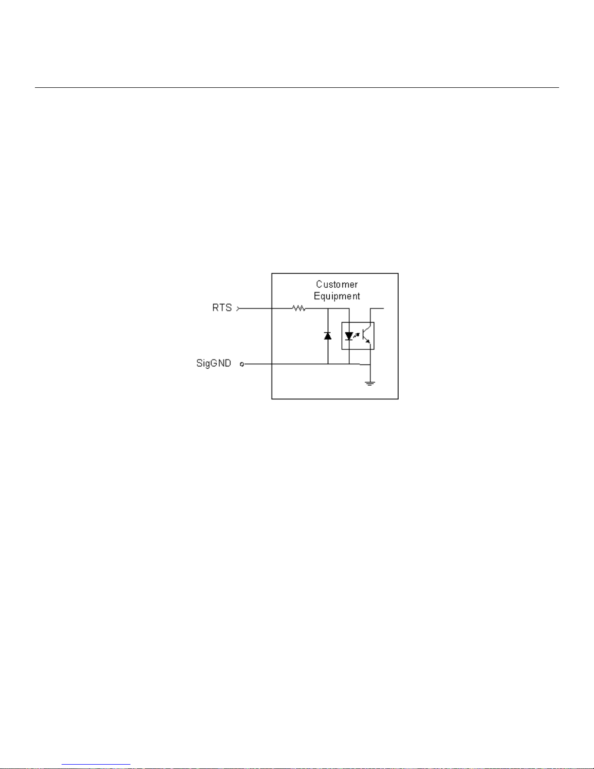
circuit is shown in Figure 21.
Important design issues to remember are:
• Special design attention is required when using Control Outputs in a control subsystem.
• Upon a restart or power up the states of DTR and RTS will transition several times as the LXSeries begins its start-up initialization.
451-0308 MRV Communications, Inc. www.mrv.com 43
Page 44
Alternative Port Capabilities
• The states are undefined upwards of 30 Seconds + the Boot Delay Timer value in some
configurations, i.e. the signals are non-latching through power cycles.
• Note that negative voltage could be present on the interface until the software is completely
initialized.
• Control Outputs in the LX-Series guarantee ±5.0V drive into a 3K Ohm load.
• External loading below 3K Ohm can be tolerated but under no circumstances should the device
load the LX-Series output below ±2.5V/7.6mA absolute maximum drive.
• A common Signal Ground is required.
• The MRV Corporation IR-7104 family can provide true Form C SPDT Relay outputs rated to
30VDC/1A per contact if higher capacity and stable contacts are required through restart and
power cycles.
Figure 21 - Typical Interface Design for Control Output Signals
You must change the LX-Series port access type to control to utilize DTR and RTS as the Control
Outputs. For example:
InReach:0>> config port async # access control
If you want the DTR signal to be asserted High (positive voltage) on the port:
InReach:0>> control port async # dtr high
Refer to the LX-Series Configuration Guide for a detailed explanation of the commands to set up a
port in the Control function.
44
MRV Communications, Inc. www.mrv.com 451-0308
Page 45

Appendix A - Technical Specifications
The following table provides the specifications for the LX-4000 Series.
Table 1 - LX-4000 Series Specifications
Item Description
Terminal Signals Transmit Data, Receive Data, Signal Ground, Data Set Ready/
Data Carrier Detect (DSR/DCD), Data Terminal Ready (DTR),
Clear-to-Send (CTS), and Request-to-Send (RTS). Supports concurrent modem control.
Terminal Cabling Modular RJ-45 DTE
Serial Line Speed LX-4000 Series - 134.5 bps to 230 Kbps
Number of Serial Ports LX 4008 - 8 ports
LX 4016 - 16 ports
LX-4032 - 32 ports
LX-4048 - 48 ports
Modem (optional) V.90/K56flex 56 Kbps
LEDs FLT, OK, Port Status LEDs 1-8 (1-16 on 16 port, 1-32 on 32 port,
1-48 on 48 port), 10/100 Ethernet RCV, 10/100 Ethernet Link,
100Mbps speed
Controls Reset push button switch
Dimensions
Height
Depth
Width
LX-4000 Series
4.34 cm (1.71 in)
21.6 cm (8.5 in)
44.45 cm (17.5 in)
451-0308 MRV Communications, Inc. www.mrv.com 45
Page 46

Appendix A - Technical Specifications
Weight (unpackaged, no
cables)
LX 4008 - 2.7 kg (6.0 lbs)
LX-4016 - 3.06 kg (6.75 lbs)
LX-4032 - 3.4 kg (7.5 lbs)
LX-4048 - 3.47 kg (7.65 lbs)
Processor/Speeds LX-4008, LX-4016:
66 MHz PowerPC system board processor with integral 33 MHz
communication co-processor, plus:
LX-4008 - Two 60 MHz RISC asynchronous communication coprocessors
LX-4016 - Four 60 MHz RISC asynchronous communication coprocessors
LX-4032, LX-4048:
100 MHz PowerPC system board processor with integral 50 MHz
communication co-processor, plus:
LX-4032 - Eight 60 MHz RISC asynchronous communication coprocessors
LX-4048 - Twelve 60 MHz RISC asynchronous communication
co-processors
Memory LX-4008, LX-4016:
8 MB Flash, 64 MB SDRAM
LX-4032, LX-4048:
8 MB Flash, 128 MB SDRAM
Environment 5% to 90% humidity, noncondensing
Operating Temperature: 0 to 40°C (32° to 104° F)
Storage Temperature: -40 to 85°C (-40 to 185° F)
Input Voltage 100 - 240 VAC 50 - 60 Hz (All LX-4000 Series)
Cable Length - Alarm
150 meters (500 feet)
Input
Cable Length - Control
300 Meters (1000 feet)
Output
46
MRV Communications, Inc. www.mrv.com 451-0308
Page 47

Appendix A - Technical Specifications
Power Requirements LX-4008 AC - 11W, (38BTU/hr) 0.09A at 120V (typ), 11W 0.05A
at 220V (typ)
LX-4008 DC - -48VDC Nominal, -20VDC to -72VDC Operating
Range, 1A @ -48VDC, Dual Feed, 165 BTU/hr
LX-4016 AC - 14W, (47.8 BTU/hr) 0.11A at 120V (typ), 14W
0.06A at 220V (typ)
LX-4016 DC - -48VDC Nominal, -20VDC to -72VDC Operating
Range, 1.2A @ -20VDC, Dual Feed, 165 BTU/hr
LX-4032AC - 23W, (79 BTU/hr) 0.19A @ 120V (typ), 0.105A @
220V
LX-4032DC - -48VDC Nominal, -20VDC to -72VDC Operating
Range, 0.6A @ 48VDC, Dual Feed, (99 BTU/hr)
LX-4048AC - 41W, (140 BTU/hr) 0.24A @ 120V (typ), 0.13A @
220V
Minimum Software
Requirements
LX-4008 requires V2.0.0 or greater, LX-4016 requires V2.0.1 or
greater, LX-4032 requires V2.2.0 or greater, LX-4048 requires
V3.0.0 or greater.
Ethernet Interface 10BASE-T/100Base-TX on single RJ-45, Auto-negotiation, Stan-
dard CSMA/CD or Full-Duplex operation.
Control Output Ratings RTS/DTR: 5.0V @ 1.6mA (Nominal), 2.5V @ 7.6mA (Absolute
Maximum)
Real Time Clock
Battery
32.768KHz crystal
Lithium coin cell battery CR2032 or equivalent. Power down
shelf-life: 1 year at 20
0
C.
451-0308 MRV Communications, Inc. www.mrv.com 47
Page 48
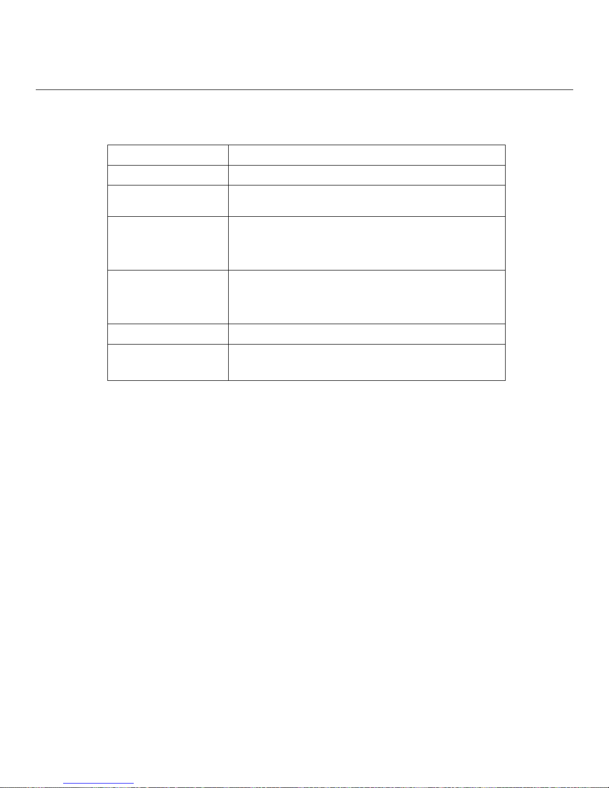
Appendix A - Technical Specifications
The following table provides the specifications for the Temperature/Humidity Sensor.
Table 2 - Temperature/Humidity Sensor Specifications
Item Description
Interface Proprietary
Maximum Cable
50 feet
Length
Operating Environment
5% to 90% humidity, noncondensing
Operating Temperature: 0 to 40°C (32° to 104° F)
Storage Temperature: -40 to 85°C (-40 to 185° F)
Dimensions Height: 0.8 inches
Length: 3.15 inches
Width: 1.57 inches
Weight 1.2 oz
Accuracy Temp: +/-3 deg C
Humidity: +/- 5%
48
MRV Communications, Inc. www.mrv.com 451-0308
Page 49

Appendix B - Factory Defaults
The following table provides the factory defaults for the LX-4000 Series.
Table 3 - LX-4000 Series Factory Defaults
Item Description
DIAG Port/local management port (default
settings)
All Ports Except Management and Modem
Ports (default settings)
Modem Port (default settings) Autobaud is disabled.
The DIAG port (port 0) is the console management port.
Auto Protocol Detect (APD) is disabled.
Autobaud is disabled.
9600/8/1/None.
Quick Start is enabled.
Access is Local.
Flow Control is Xon/Xoff.
Autobaud is disabled.
9600/8/1/None.
Access is Remote.
APD is disabled.
Flow Control is Xon/Xoff.
Speed is 57600.
Access is Local.
APD is enabled.
Flow Control is CTS.
451-0308 MRV Communications, Inc. www.mrv.com 49
Page 50

Appendix B - Factory Defaults
ppciboot Factory Default Settings
The following table lists the factory default settings.
Main Menu Configuration Factory Default Setting
Boot from Network yes
Save boot image to flash no
Boot from flash yes
Time Out, in seconds 8
IP Configuration Menu Configuration
IP Assignment method #1 DHCP
IP Assignment method #2 BOOTP
IP Assignment method #3 RARP
IP Assignment method #4 User Defined
NOTE: For defaults on specific commands, refer to the LX-Series Commands Reference Guide.
Each LX Series unit is configured at the factory to use a default set of initialization
parameters that sets all ports to operate with asynchronous ASCII terminal devices.
Factory Default Setting
50
MRV Communications, Inc. www.mrv.com 451-0308
Page 51

Error Code Definitions
The following table provides the definitions for the LX-4000 Series POST test error codes.
Error Definition Error Code (in Hexa-
CPU Clock Slow 1020
Reading Invalid Default Value from CPLD Diagnostic Register 2010
Appendix C - POST Test Error Codes
Table 4 - POST Test Error Codes
decimal)
Reading Invalid Default Value from Expansion CPLD Diagnostic Register
Reading Invalid Pattern Value from CPLD Diagnostic Register 2020
Reading Invalid Pattern Value from Expansion CPLD Diagnostic Register
Reading Invalid Value from CPLD System Fail Status Register 2030
AC FAIL bit is set in the CPLD System Fail Status Register 2031
+12VFAIL bit is set in the CPLD System Fail Status Register 2033
-12VFAIL bit is set in the CPLD System Fail Status Register 2034
CPLD FAIL bit is set in the CPLD System Fail Status Register 2035
Watchdog Timer Failed 2040
Invalid HW Type 2050
Fast Ethernet Controller (FEC) Reset Delay Timeout 3010
Fast Ethernet Controller (FEC) Transmission Failed Timeout 3020
2011
2021
451-0308 MRV Communications, Inc. www.mrv.com 51
Page 52

Appendix C - POST Test Error Codes
Fast Ethernet Controller (FEC) Reception Failed Timeout 3030
Fast Ethernet Controller (FEC) Invalid Data Received 3040
No PHY Device Detected 3050
CD1400 Reset delay timeout for Quadart 1 4110
CD1400 Reset delay timeout for Quadart 2 4120
CD1400 Reset delay timeout for Quadart 3 4130
CD1400 Reset delay timeout for Quadart 4 4140
CD1400 Reset delay timeout for Quadart 5 4150
CD1400 Reset delay timeout for Quadart 6 4160
CD1400 Reset delay timeout for Quadart 7 4170
CD1400 Reset delay timeout for Quadart 8 4180
CD1400 Reset delay timeout for Quadart 9 4190
CD1400 Reset delay timeout for Quadart 10 41A0
CD1400 Reset delay timeout for Quadart 11 41B0
CD1400 Reset delay timeout for Quadart 12 41C0
CD1400 Loopback operation timeout for Quadart 1 4210
CD1400 Loopback operation timeout for Quadart 2 4220
CD1400 Loopback operation timeout for Quadart 3 4230
CD1400 Loopback operation timeout for Quadart 4 4240
CD1400 Loopback operation timeout for Quadart 5 4250
CD1400 Loopback operation timeout for Quadart 6 4260
CD1400 Loopback operation timeout for Quadart 7 4270
CD1400 Loopback operation timeout for Quadart 8 4280
CD1400 Loopback operation timeout for Quadart 9 4290
CD1400 Loopback operation timeout for Quadart 10 42A0
CD1400 Loopback operation timeout for Quadart 11 42B0
CD1400 Loopback operation timeout for Quadart 12 42C0
CD1400 Invalid Data Received for Quadart 1 4410
CD1400 Invalid Data Received for Quadart 2 4420
CD1400 Invalid Data Received for Quadart 3 4430
CD1400 Invalid Data Received for Quadart 4 4440
CD1400 Invalid Data Received for Quadart 5 4450
52
MRV Communications, Inc. www.mrv.com 451-0308
Page 53

CD1400 Invalid Data Received for Quadart 6 4460
CD1400 Invalid Data Received for Quadart 7 4470
CD1400 Invalid Data Received for Quadart 8 4480
CD1400 Invalid Data Received for Quadart 9 4490
CD1400 Invalid Data Received for Quadart A0 44A0
CD1400 Invalid Data Received for Quadart B0 44B0
CD1400 Invalid Data Received for Quadart C0 44C0
Memory Error at (printing address) 5010
Memory Data Bus Failed 5020
Memory Address Bus Failed High 5030
Memory Address Bus Failed Low 5040
Flash Checksum Error 5055
POST Test Error Code Sample
Appendix C - POST Test Error Codes
NOTE: This example applies to 8, 16, 32, and 48 port LX units. The 16, 32, and 48 port
LX units use only the first eight LEDs when generating error codes.
The following sample illustrates the Port Status LED sequence for Error 2030 (Reading Invalid Value
from PLD System Fail Status Register) on the LX-4008. In this example:
1. A POST test failure occurs on an 8-port unit. All LEDs flash eight times, very quickly, then the error code
is displayed.
2. You record that LED 3 turns on. Again, all LEDs flash eight times very quickly, then the rest of the error
code is displayed.
3. You record that LEDs 3 and 4 turn on. Figure 22 explains how to interpret the sample error code.
NOTE: In hexadecimal, 0 indicates the LED is OFF. 1 indicates the LED is ON.
Each group of four LEDs is converted to a hexadecimal value as follows:
• 0 = 0000
• 1 = 0001
• 2 = 0010
• 3 = 0011
• 4 = 0100
• 5 = 0101
• 6 = 0110
• 7 = 0111
• 8 = 1000
• 9 = 1001
451-0308 MRV Communications, Inc. www.mrv.com 53
Page 54
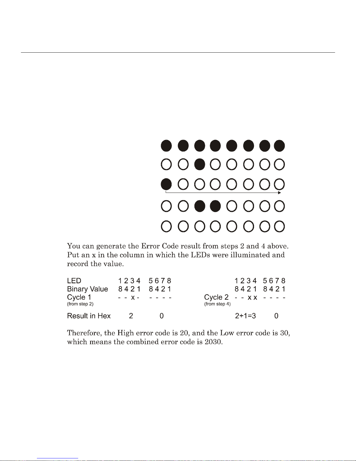
Appendix C - POST Test Error Codes
• A = 1010
• B = 1011
• C = 1100
• D = 1101
• E = 1110
• F = 1111
1 - All flash for 2 secon ds
2 - High error code (20 Hex)
3 - Cycle 1 through 8
4 - Low error cod e (3 0 H ex)
1 2 3 4 5 6 7 8
5 - All extinguished
Figure 22 - POST Test Error Code Sample
54
MRV Communications, Inc. www.mrv.com 451-0308
Page 55

Cabling Considerations
Standard cabling items available from MRV allow you to connect to any serial device that uses male
or female DB-25 or DB-9 connectors. All you need is the appropriate cable (crossover cable for
connecting to a DTE (Data Terminal Equipment) device, straight-through cable for connecting to a
DCE (Data Communication Equipment) device), and the correct modular adapter (male or female DB25 connector), which is essentially an RJ-45-to-DB25 adapter.
Serial Device Connectors
The signal assignments of the 8-pin jacks are shown in Figure 23.
Appendix D - Cabling the LX-4000 Series
12345678 1234
Rj-45 Jack
Figure 23 - Serial Device Connector (RJ-45) Signal Assignments
Diagnostic Port Connector (Port 0)
The pinout for the Diagnostic Port connector is the same as that of the serial connector.
(Female)
56
78
Rj-45 Plug
(Male)
Pin Signal
1 CTS
2 DTR
3 TXD
4 SGND
5 SGND
6 RXD
7 DSR
8 RTS
451-0308 MRV Communications, Inc. www.mrv.com 55
Page 56
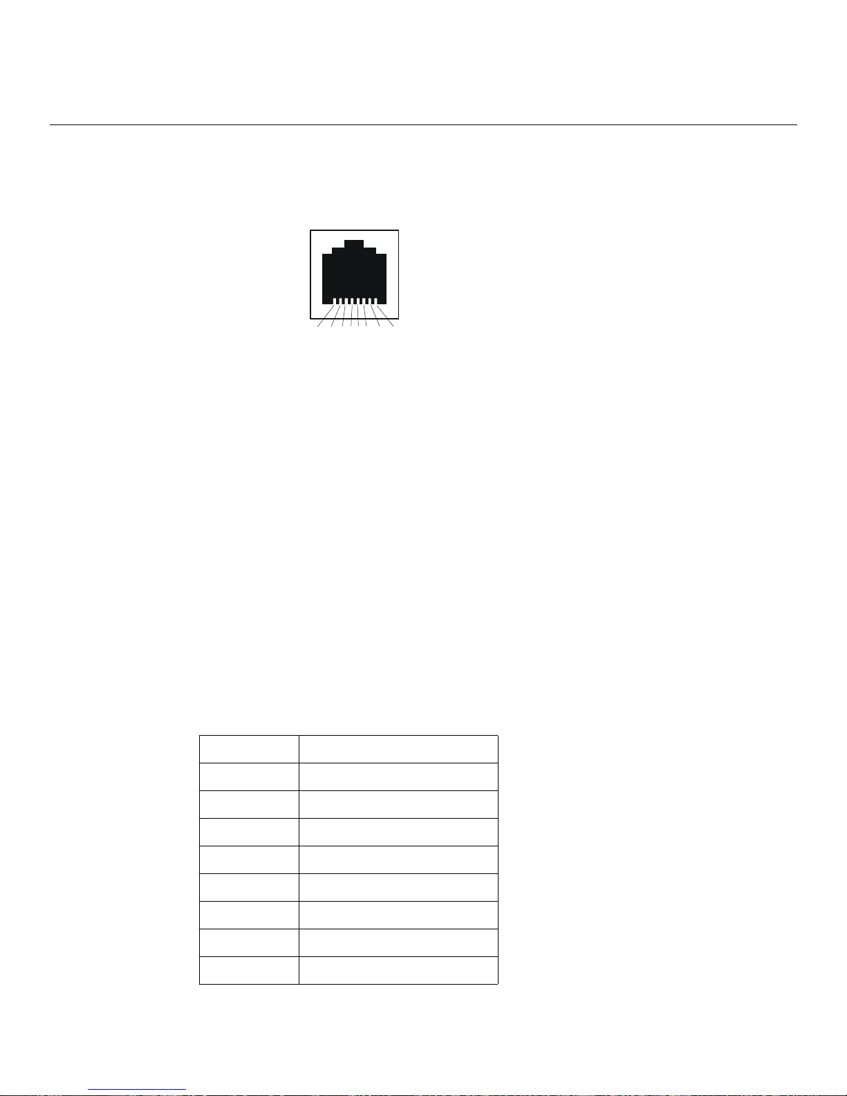
Appendix D - Cabling the LX-4000 Series
10/100 Connector
Figure 24 shows the standard 10/100 (RJ-45 jack) connector signal assignments.
Figure 24 - 10/100 Connector Assignments
Ordering Cables
MRV also supplies crossover cables and modular adapters for use with all LX-4000 Series units. To
order cables, adapters or other cabling accessories from MRV, contact your Sales representative or
distributor.
8 7 6 5 4 3 2 1
Pin Signal
1 TX+
2 TX3 RX+
4 No Connect
5 No Connect
6 RX7 No Connect
8 No Connect
Modular Adapters
MRV provides the following modular adapters for use with LX-4000 Series units:
• Female DB-9 (PN MX-350-0308)
• Female DB-25 (PN MX-350-0181)
• Male DB-25 (PN MX-350-0179) – supports RING
• Male DB-25 (PN MX-350-0180) – supports RTS/CTS
This section describes the pinouts and wiring of the MRV-supplied DB-25 adapter.
Pin Assignments
The following table shows the pinouts for a standard RS-232 DB-25 connector.
Pin Signal
1 Cable Shield
2 Transmit Data
3 Receive Data to DCE
4 RTS (Request to Send)
5CTS (Clear to Send)
6 DSR (Data Set Ready)
7Signal Ground
8 Data Carrier Detect
56
MRV Communications, Inc. www.mrv.com 451-0308
Page 57
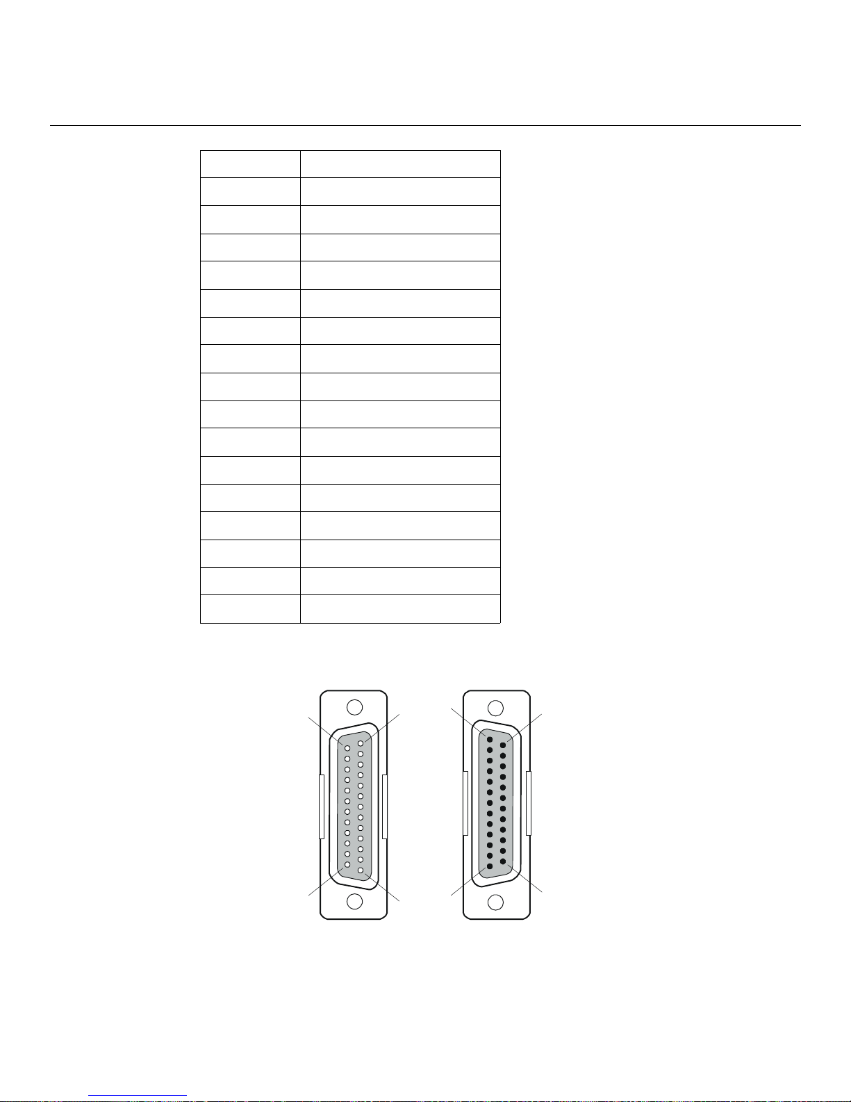
9Unused
10 Unused
11 Unused
12 Unused
13 Unused
14 Unused
15 Unused
16 Unused
17 Unused
18 Unused
19 Unused
20 Data Terminal Ready
21 Unused
Appendix D - Cabling the LX-4000 Series
22 Ring Indicate
23 Unused
24 Unused
25 Unused
Figure 25 shows serial DB-25 pin assignments.
14
25
1
13
1
13
14
25
451-0308 MRV Communications, Inc. www.mrv.com 57
DB-25
(Male)
Figure 25 - DB-25 Pins
DB-25
(Female)
Page 58
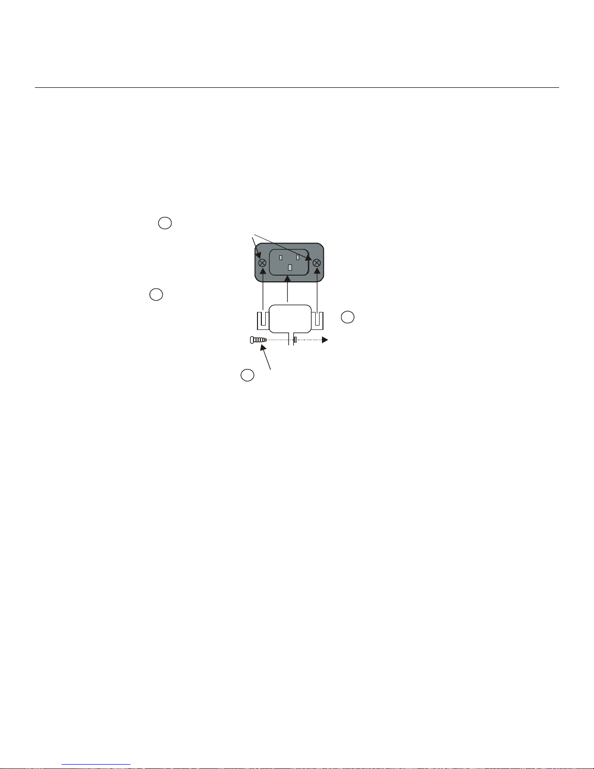
Appendix D - Cabling the LX-4000 Series
Ordering and Installing the Inlet Connector Lock
NOTE: The Inlet Connector Lock is available only on the LX-4008, LX-4016, and LX-4032. It is not
supported on the LX-4048.
You can use an inlet connector lock to lock the AC power cord to the LX-4000 Series unit. MRV does
not supply this lock. You can order the connector lock (part number 85910020) from Panel
Components Corporation. The web address at which you can order the connector lock is:
www.panelcomponents.com/first.html. See Figure 26 for installation instructions.
Insert two 4-40 x
1
1/4” Phili p s screws
here. Do not
tighten.
Slide the connector
2
lock ears under the
screw heads.
Tighten the screws.
90-250VAC
1.0A 50/60Hz
Plug in the power cord
3
(not shown).
Tighten the screw
4
beneath the conne cto r
lock.
Figure 26 - Installing the Inlet Connector Lock
Connecting to the Diagnostic Port (Port 0)
NOTE: Display problems may occur during bootup when you attach a VT420 terminal to the DIAG
port (port 0) and the VT420 display setup is configured to Smooth-2 Scroll. To avoid this,
change the VT420 scroll setting to Jump Scroll.
Connect the provided serial port cable to the DIAG connector (port 0), and the other end to your
terminal. You can use this direct connect serial link to send commands to the boot loader and
diagnostics. This port is used to log system messages during bootup. You can also use port 0 to
manage and configure the LX-4000 once the unit completes the bootstrap process.
Modem Control/Hardware Flow Control
LX-4000 Series serial ports can be set up to support RTS/CTS flow control. The adapters shown in
Figure 27 and Figure 28 illustrate RTS/CTS flow control for DTE devices using DB25 and DB9
connectors. Figure 29 illustrates RTS/CTS flow control for a DB-25 connector on a DCE device like a
modem. LX-4000 Series serial ports can also be set up to support modem control (except for the DIAG
port (port 0)). Figure 27, Figure 28, and Figure 29 support modem control as needed. Only Figure 28
and Figure 29 support concurrent modem control and RTS/CTS flow control between the LX-4000
Serial Port and the attached device.
The adapter shown in Figure 29 supports modem control.
58
MRV Communications, Inc. www.mrv.com 451-0308
Page 59
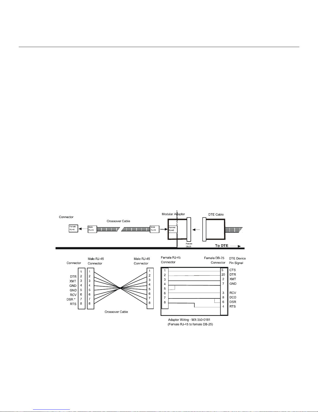
NOTE: You would use a "null-modem" cable when making a direct connection between the serial
ports of two communication servers (i.e., no modems involved) or other DTE device. For that
application, use a DTE-to-DTE cable.
RJ-45 Wiring Considerations
You should give special consideration to the wiring scheme when connecting a device such as a
terminal to a LX-4000 Series serial port. The LX-4000 Series is considered a DTE device. To connect
to another DTE device such as a terminal, you will need crossover wiring, as shown in Figure 27 and
Figure 28. When a DCE device is connected to an LX-4000 Series serial port, straight-through wiring
is required, as shown in Figure 29.
NOTE: In general, an ethernet category 3 (CAT 3) or category 5 (CAT 5) may introduce noise due to
the crossing of pins 3 and 6 (transmit and receive). Flat eight wire cables are recommended.
Modular Adapters (RJ-45 to DB-25)
You can obtain adapters with male and female DB-25 connectors from MRV. These adapters direct
signals from the RJ-45 connector on the cable to the correct pin on the DB-25 connector. Figure 27,
Figure 28, and Figure 29 show how devices are cabled when you use these adapters.
Application (see Figure 27): Use RJ-45 to DB-25 to connect your LX-Series unit to a PC.
Appendix D - Cabling the LX-4000 Series
LX Serie s
MAXserver
Connector
MAXserver
LX Se ri e s
Connector
CTS/RING
XMTGND
RCVGND
DSR *
Female
RJ-45
CTS
DTR
XMT
RCV
RTS
(See Note, Page 5.)
*
1
2
3
4
5
6
7
8
Male
RJ-45
Male RJ-45
Connector
1
2
3
4
5
6
7
8
Crossover Cable
Male RJ-45
Connector
Crossover Cable
MX-151-3028
Male
RJ-45
1
2
3
4
5
6
7
8
Modular Adaptor
Female
RJ-45
Female
DB-25
Female RJ-45
Connector
1
2
3
4
5
6
7
8
Adaptor Wiring - MX-350-0181
(Female RJ-45 to female DB - 25)
DTE Cable
To DTE
Female DB-25
Connector
5
20
2
7
3
8
6
4
DTE Device
Pin Signal
CTS
DTR
XMT
GND
RCV
DCD
DSR
RTS
Figure 27 - Adapter Wiring, LX Series to DTE
451-0308 MRV Communications, Inc. www.mrv.com 59
Page 60
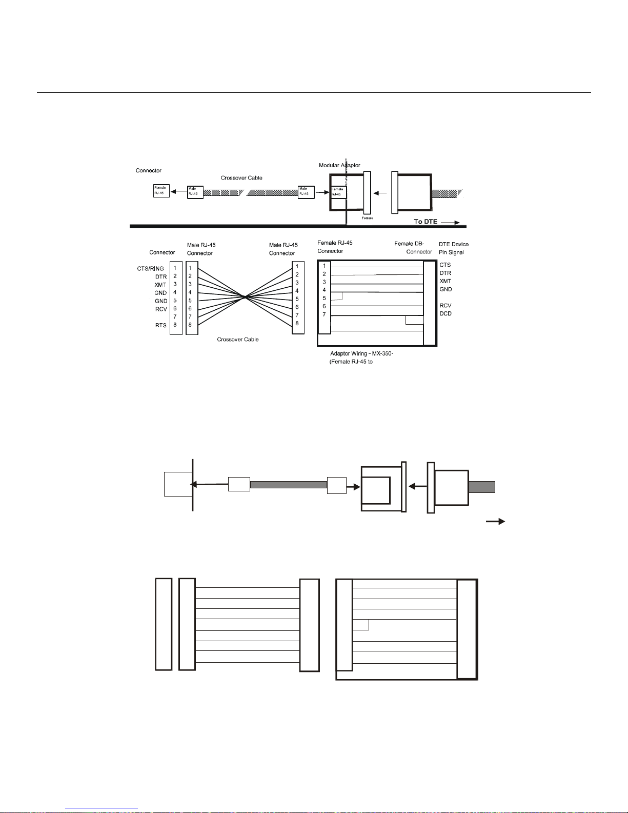
Appendix D - Cabling the LX-4000 Series
A
Application (see Figure 28): Use RJ-45 to DB-9 to connect your LX-Series unit to a PC or other serial
port using a D sub-9 connector.
LX Se rie s
MAXserver
Connector
Female
RJ-45
Male
RJ-45
Crossover Cable
Male
RJ-45
Modular Adaptor
Female
RJ-45
DB-9 Cable
DTE Cable
MAXserver
LX Se rie s
Connector
CTS/RING
DTR
XMT
XMTGND
RCVGND
RCV
DSR *
DCD
RTS
(See Note, Page 5.)
*
Male RJ-45
Connector
1
1
2
2
3
3
4
4
5
5
6
6
7
7
8
8
MX-151-3028
Crossover Cable
Male RJ-45
Connector
1
2
3
4
5
6
7
8
Female
DB -9
DB-25
Female RJ-45
Connector
1
2
3
4
5
6
7
8
8
Adaptor Wiring - MX-350-0181
(Female RJ-45 to female DB-25)
Female DB-9)
To DTE
Female DB-25
Connector
0308
9
5
8
20
4
2
3
7
5
3
2
8
1
6
6
4
7
DTE Device
Pin Signal
CTS
DTR
XMT
GND
RCV
DCD
DSR
DSR
RTS
RTS
Figure 28 - Adapter Wiring, RJ-45 to DB-9, LX Series to DTE
Application (see Figure 29): Use LX-Series to DCE to connect your LX-Series unit to a modem.
LX Series
Connector
Fem a le
RJ-45
Male
RJ-4 5
Stra ig h t Th ro u g h
Cable
Modular
daptor
Male
RJ-4 5
Fem a le
RJ-4 5
Modem
Cable
Su pports RTS/C TS
LX Serie s
Connector
CTS
DTR
XMT
GND
GND
RCV
DCD
RTS
60
Male RJ-45
Connector
1
1
2
2
3
3
4
4
5
5
6
6
7
7
8
8
St ra i g h t Through Cable
MRV Communications, Inc. www.mrv.com 451-0308
Male
DB-25
MX-151-3027
Male RJ-45
Connector
1
2
3
4
5
6
7
8
Fem a l e RJ-4 5
Connector
1
2
3
4
5
6
7
8
Adaptor Wiring MX-350-0180
(Female RJ-45 to male DB-25)
Figure 29 - Adapter Wiring, LX Series to DCE
To Modem
Male DB-25
Connector
5
20
2
7
3
8
4
DCE Devic e
Pin Sig na l
CTS
DTR
XMT
GND
RCV
DCD
RTS
Page 61
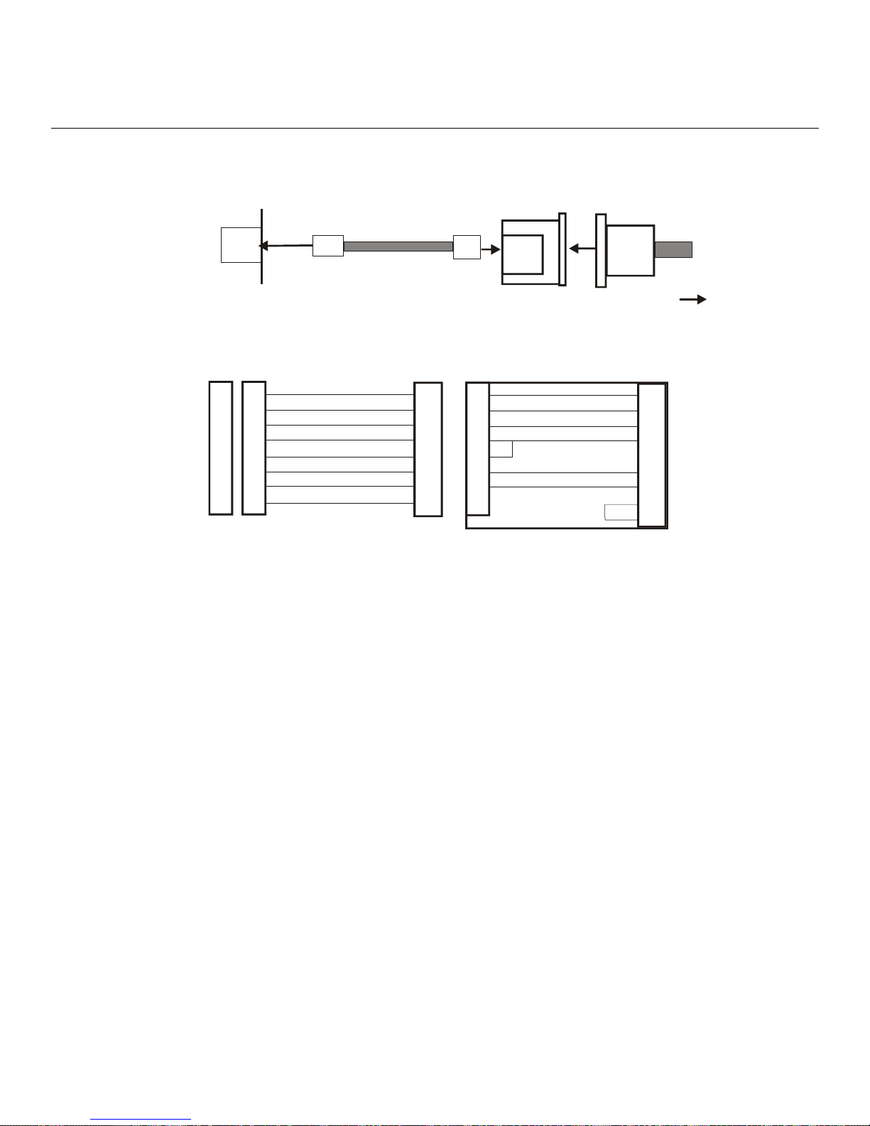
Appendix D - Cabling the LX-4000 Series
A
LX Series
Connector
Female
RJ-45
Supports RING
LX Series
Connector
CTS
DTR
XMT
GND
GND
RCV
DCD
RTS
1
2
3
4
5
6
7
8
Male RJ-45
Connector
1
2
3
4
5
6
7
8
Male
Straight Through
RJ-45
Cable
Straight Through Cable
MX-151-3027
Male RJ-45
Connector
1
2
3
4
5
6
7
8
Male
RJ-45
Female RJ-45
Connector
1
2
3
4
5
6
7
8
Modular
daptor
Female
RJ-45
Male
DB-25
Adaptor W i ring MX-350-0179
(Female RJ-45 to male DB-25)
Modem
Cable
To Modem
Male DB-25
Connector
Figure 30 - Adapter Wiring, LX-Series to DCE, with RING
22
20
2
7
3
8
4
5
DCE Device
Pin Signal
RI
DTR
TXD
GND
RXD
CD
RTS
CTS
NOTE: In order to expand the functionality of the serial interface, the LX-4000 Series modular
cabling allows you to connect different signals to pin 7 of the LX-4000 Series. (This pin is an
input to the LX-4000 Series.) When a DCE device is connected to an LX-4000 Series serial
port, the device's DCD output is connected to pin 7. In this case, the signal at pin 7 is
referred to as DCD. DCD is used here for session control only, not for flow control.
When a DTE device is connected to an LX-4000 Series serial port, the device's DTR output is
connected to pin 7 of the LX-4000 Series. In this case, the signal at pin 7 is referred to as
DSR. (This cabling scheme also provides DECconnect compatibility, since DECconnect does
not support the DCD signal.)
MRV 8-Wire Cabling
This cabling scheme provides XMT, RCV, DCD/DSR, DTR, RTS, CTS, and two signal ground wires.
This cabling is provided through RJ-45 connectors. Using this cabling scheme you can concurrently
use modem control and RTS/CTS hardware flow control, since there are four control signals. This
scheme is useful with relatively high speed devices, complex modem control applications.
In Figure 31, one signal is referred to as CTS. The CTS signal designation refers to the signal
observed at pin 1 of each serial port. Pin 1 is multiplexed to these signals.
This scheme is useful with the following applications:
451-0308 MRV Communications, Inc. www.mrv.com 61
Page 62
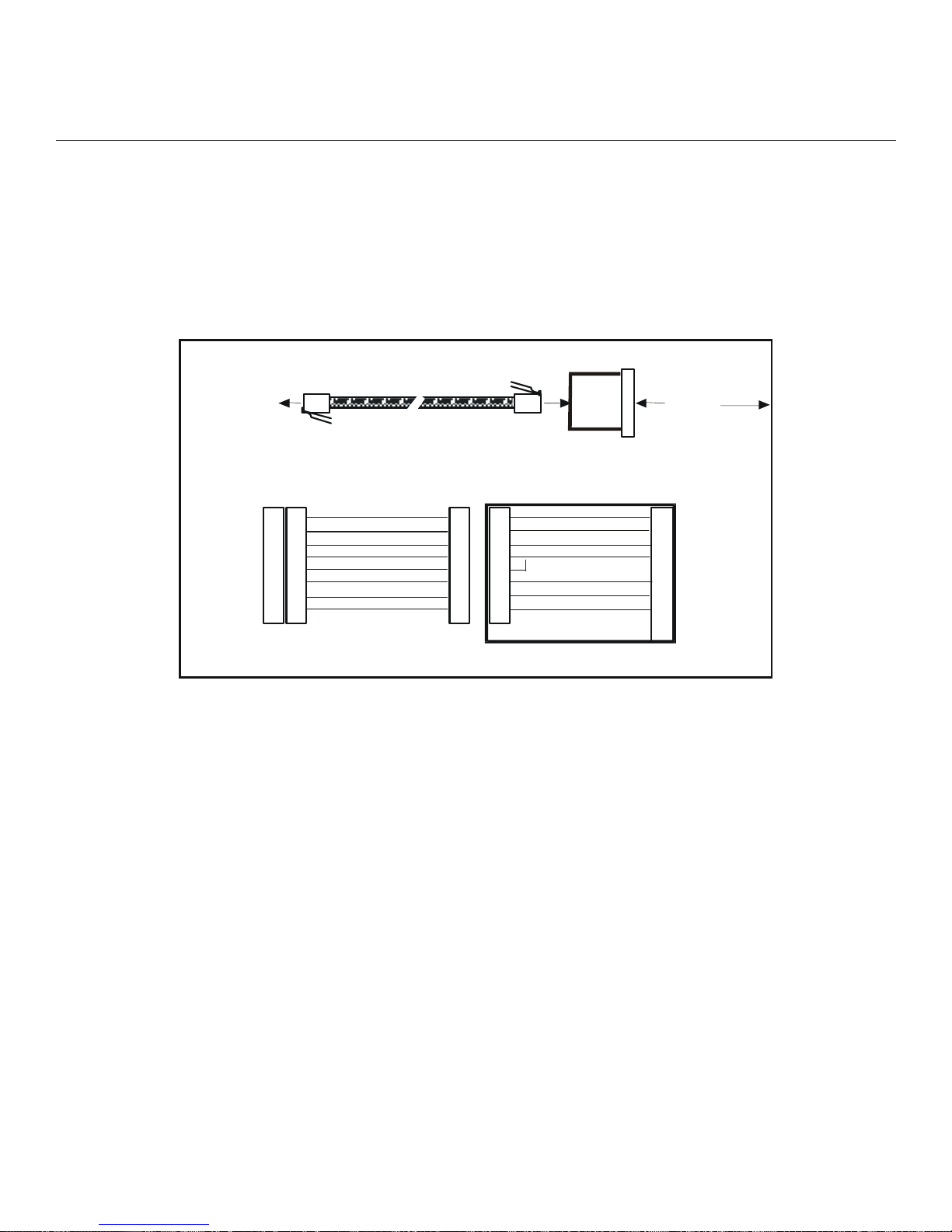
Appendix D - Cabling the LX-4000 Series
• Terminal emulation and file transfer applications, such as Kermit, Xmodem, Microphone, etc.
• Applications such as PPP using low speed modems.
• Applications such as PPP using high speed modems.
• Applications using CCITT V.42-compliant modems, or other devices operating at high port
speeds.
Application (see Figure 31): Use RTS/CTS to connect your LX-Series unit to a modem.
RTS/CTS Modem Connection
RTS/CTS Modem Connection
LX Series
Communication
Communication
Serv er Co nnector
Serv er Co nnector
Connector
Female RJ-45
Female RJ-45
Connector
Connector
CTS/RING
CTS/RING
CTS
DTR
DTR
XMT
XMT
XMTGND
XMTGND
RCVGND
RCVGND
RCV
RCV
DCD
DCD
RTS
RTS
1
1
2
2
3
3
4
4
5
5
6
6
7
7
8
8
Male RJ-45
Male RJ-45
Connector
Connector
1
1
2
2
3
3
4
4
5
5
6
6
7
7
8
8
St raight Through Cable
St raight Through Cable
MX-151-3027
St raight Through Cable
St raight Through Cable
Male RJ-45
Male RJ-45
Connector
Connector
1
1
2
2
3
3
4
4
5
5
6
6
7
7
8
8
Modu lar A dapt or
Modu lar A dapt or
F em ale R J-45
F em ale R J-45
Connector
Connector
1
1
2
2
3
3
4
4
5
5
6
6
7
7
8
8
Adaptor Wiring - MX-350-0180
Adaptor Wiring - MX-350-0180
(F emale R J- 45 t o mal e D B-2 5)
(F emale R J- 45 t o mal e D B-2 5)
Male DB-25
Male DB-25
Connector
Connector
To M o de m
To M o de m
Modem connec tor
Modem connec tor
Pin Signal
Pin Signal
CTS
CTS
5
5
DTR
DTR
20
20
XMT
XMT
2
2
GND
GND
7
7
RCV
RCV
3
3
DCD
DCD
8
8
RTS
RTS
4
4
Figure 31 - Modular Cables for RTS/CTS Flow Control (Eight-Wire), Conc ur-
rent with Modem Control Signalling
62
MRV Communications, Inc. www.mrv.com 451-0308
Page 63

INDEX
Numerics
10/100 connectors 56
4800 power management 41
4800 series
connecting to 41
5150 power management 40
5150 series
connecting to 40
5250 Power Management 38
5250 Series
connecting to 39
8-wire cabling 61
A
adapter wiring 59
adapters 59
alarm input setup 42
autobauding feature 36
C
cables
ordering 56
cabling 20
signals 61
command recall 14
configured 50
Configuring the LX-4000 Unit for the First Time 25
connecting DC power 21
connecting the power cable 20
connecting to a serial port 34
control output setup 43
conventions 13
crossover cables 55
D
DB-25 connectors 59
DB-25 pin assignments 61
DC power
connecting 21
diagnostic port connector 55
DTE devices
connecting to LX-4000 Series 61
DTE wiring 59
E
environment 19
environmental considerations 19
error code definitions 51
ethernet connection 21
F
first time quick configuration 25
flow control 58
FLT - fault LED 16
front panel LEDs 16
G
Graphic User Interface (GUI)
accessing 28
GUI EZ Configuration 33
H
hardware installation 15
help key 14
I
iBoot factory default settings 50
inlet connector lock
installing 58
ordering 58
installation
hardware 15
installing Java Runtime Environment (JRE) 29
Installing the LX Series
site requirements 45, 48, 49
internet access
IP addresses 36
internet environment 36
IP address
assigning via the network 27
manually setting 28
IP information
obtaining 27
J
Java
installing 29
L
LED
fault 16
link 19
OK 16
port status 17
receive 19
speed 19
LINK LED 19
login username 23
default 23
LX- 4000 Indicators 16
451-0308 MRV Communications, Inc. www.mrv.com 63
Page 64

INDEX
LX ports
using as alarm inputs/control outputs 42
LX Series 4008 rear panel 17
LX Series 4008 w/modem rear panel 17
LX Series 4016 DC rear panel 18
LX Series 4016 w/modem rear panel 18
LX Series 4032 DC rear panel 19
LX Series 4032 w/modem rear panel 18
LX Series 4048 AC rear panel 19
LX-4000 Series
about 13
alarm input cable length 46
cabling 45
control output cable length 46
Control Output Ratings 47
controls 45
dimensions 45
environment 46
Ethernet connections 47
LEDs 45
memory 46
minimum software requirements 47
modem 45
power requirements 47
processor 46
real time clock 47
signals 45
speeds 45
voltage 46
weight 46
LX-4000 Series ports
accessing from a terminal 35
LX-4000 Series serial ports
number of 45
LX-4000 Unit
configuring for the first time 25
LX-4008S front panel 16
LX-4016 front panel 16
LX-4032 front panel 16
LX-4048 front panel 16
M
management station
connecting to 21
manually setting the IP address 28
menu tree structure 36
modem port 22
modular adapters 56
O
OK LED 16
organization of user guide 11
P
package contents 15
passwords 23
defaults 23
pinouts
DB-25 56, 61
RJ-45 61
RJ-45 jacks 55
port status LEDs 17
ports 37
POST test error code sample 53
power cable 20
power on self test (POST) 22
powering on 22
ppciboot factory default settings 50
prompts 13
Q
quick configuration
first time 25
R
rack-mounting the unit 20
RCV LED 19
real time clock battery 47
rear panel connections 17
rear panel LEDs 17
reinitializing/powering off the unit 36
RESET switch 23
resetting the unit 23
RJ-45 jacks 21
RJ-45 wiring 59
S
sensor ports 37
serial device cables
connecting to RJ-45 jacks 21
speed LED 19
System Login 23
system specifications 14
T
tab button 14
technical specifications 45
LX-4000 Series 45, 49
temperature/humidity sensor 48
64
MRV Communications, Inc. www.mrv.com 451-0308
Page 65

INDEX
telnet directly to the communication server 34
telnet port
changing 34
temperature/humidity sensor
accuracy 48
cable length 48
connecting the 37
dimensions 48
environment 48
interface 48
weight 48
typographical conventions 14
U
Unpacking and inspecting the unit 15
W
web access mode 32
web configure mode 31
wiring schemes
for RJ-45 59
451-0308 MRV Communications, Inc. www.mrv.com 65
 Loading...