

Page 1
Page 2
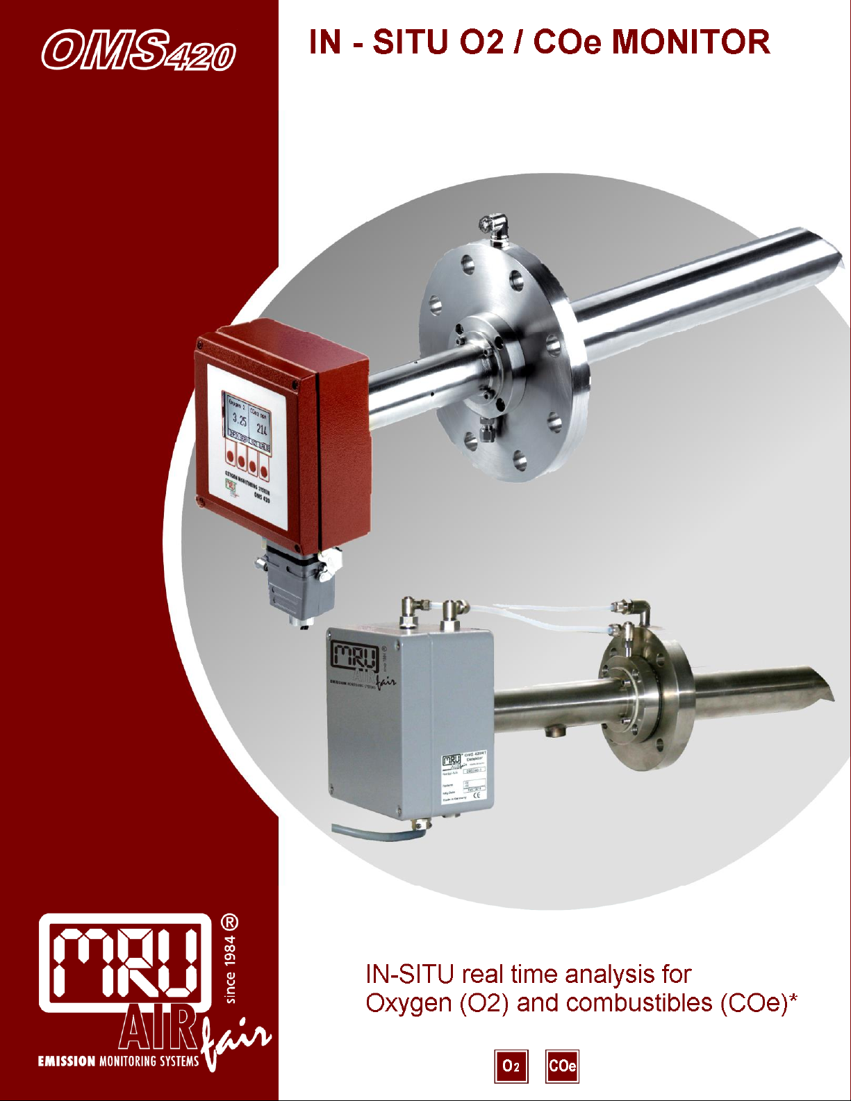
Measurement principle
Oxygen (O2) = ZrO2 zirconium dioxide
COe (combustibles) = heated solid electrolyte
* total of flue gas combustibles
(CO + H2 + CxHy)
displayed as equivalent CO
STANDARD FEATURES
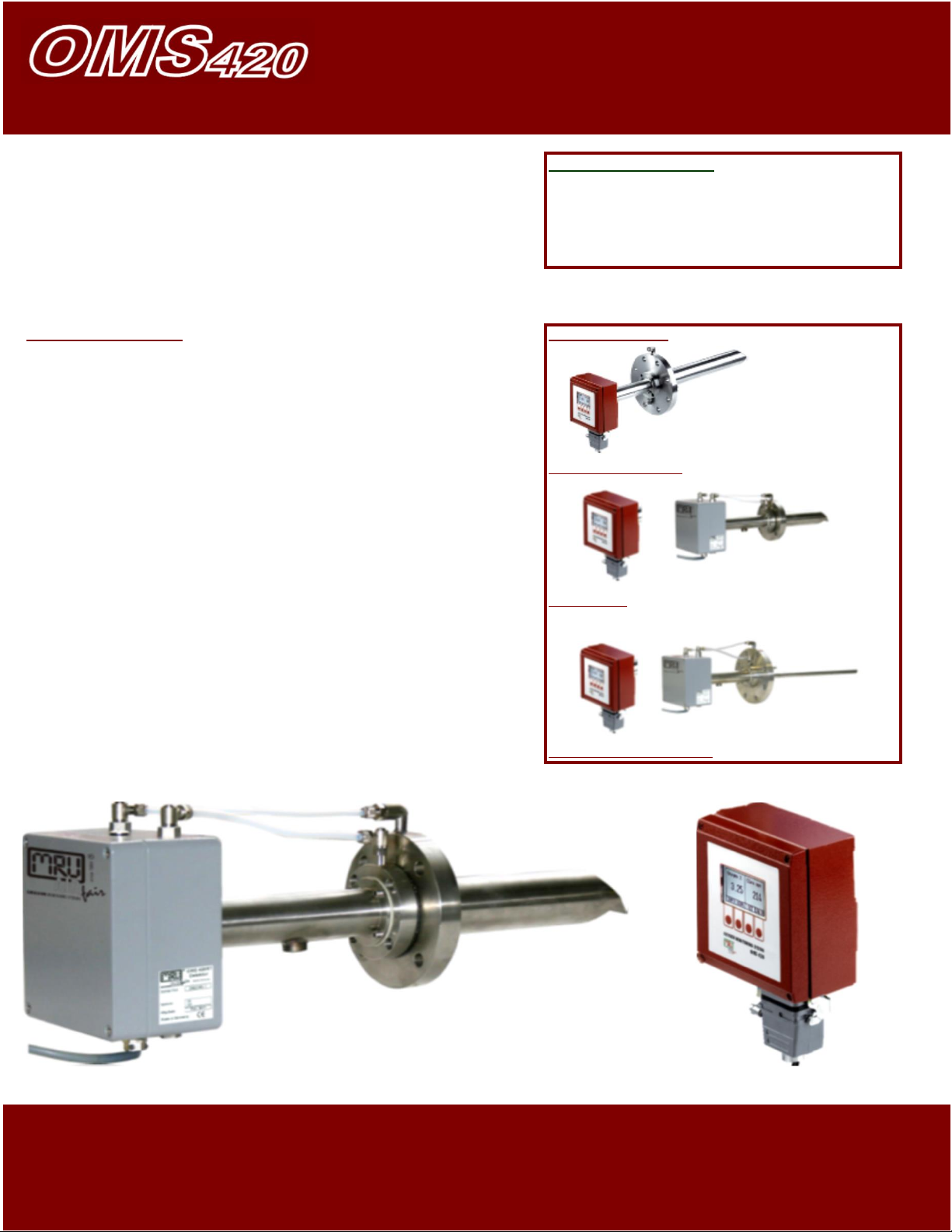
OMS 420 models
˃˃
Clean combustion (low dust)
with combustion temperatures up
to max. 1,800 °F
˃˃
Die cast aluminum enclosure with
electronics, keyboard, up-front display
OMS420 - compact
of O2 and COe
˃˃
Standard ANSI flange
(other flanges e.g. DIN on request)
Probe tube with Ø 2.4” and various
lengths.
OMS420RT
˃˃
Connector for back purge
compressed air.
˃˃
Connecting tube with reference
air inlet with small flange, Ø 3.9"
˃˃
Rugged industrial plug for power supply
and data transfer
OMS420HT High Temp.
(analog 4 … 20 mA, digital RS 485)
OMS 420-RT (remote display and control unit)
Display and control unit
IN - SITU O2 MONITOR
IN-SITU real time analysis
Oxygen (O2) and combustibles (COe)*
Page 3

Combustion-optimization diagram:
Save millions $ a year (in large power plants)
Save energy and fuel consumption
Connecting
tube
OMS control
unit and
Power supply and data
Fitting for back-purge
Probe tube
ANSI flange
Test gas inlet
The essential advantage
of the OMS 420 system
easy servicing, inspecting or
repairing the unit:
The OMS 420 transmitter
contains the electronics, display
and keyboard, the connection
tube and the small flange (Ø
3.9") are mounted on the ANSI
flange using just 4 screws.
Simply loosen the 4 screws and
change the transmitter in
minutes…
… simple and economical
replacement!
Page 4

TECHNICAL SPECIFICATIONS
DATA SUBJECT TO CHANGE WITHOUT NOTICE
Warm up time
min. 30 minutes
Measuring range
0.1 ... 25.0 % Vol.-% O2
0 ... 1,000 ppm COe (option combustibles measurement)
Accuracy
O2: ±0.2 % or ± 5 % of reading, whichever is larger
COe: ±50 ppm or ±10 % of reading, whichever is larger
Flange
ANSI flange: Ø 230mm / probe tube: Ø 60mm,
up to max. 13' (4.0 m) length or flange DN80 PN16
Flange
DN65 PN6 flange: Ø 216 mm / probe tube: Ø 60 mm
up to max. 13' (4.0 m) length or flange DN80 PN16
Flange temperature
min. +160 °F ... max. +300 °F
(condensation at the flange must be avoided)
Response time T90
<10 seconds
Analog outputs
2 x current loop 4 … 20 mA, with galvanic isolation
linearized for both 0 … 25 % O2 and 0 ... 1,000 ppm COe
(user definable settings in 0.5% steps are possible)
Digital output
galvanic isolated RS 485 ( with Modbus protocol)
Power supply
18 ... 24 Vdc (for model OMS 420), 90 ... 100 W
100 ... 240 Vac (for model OMS 420 RT and HT) max. 100 W
Power supply
18 ... 24 Vdc, 90 ... 100 W
Electronic of transmitter
with local microprocessor, display and 4 push-buttons
Calibration inlet
with test gas fitting for 6/4 mm tube cal. gas supplied manually
or automatically by pneumatic unit PU 420
Back purge inlet
min. 87 PSI … 116 PSI (6 … 8 bar) compressed air with quick connector for 8 mm tube
Ambient temperature
-70 °F ... +130 °F
of electronics
Enclosure
Die cast aluminum, 6.3" x 6.3" x 2.4" and probe tube, Ø 2"
Protection class
IP 65
Weight
7.7 lbs. (without probe and flange)
OPTIONS
COe measurement
PROBE TUBE AND SENSOR CHAMBER BLOW BACK SYSTEM. Compressed air is required!!
Blow back timing and duration are user definable. Recommended for
applications with high particulates, such as coal-fired power plants.
Automatic calibration for span and offset, using pneumatic unit PU 420
Application with high temperatures up to approx. 3,100 °F with ceramic tube and ejector (model HT)
Remote control and display unit
(max. cable length = approx. 33’ - model RT) for applications with ambient temperature >120 °F
MRU Instruments, Inc.
Houston, Texas 77044
Tel.: (832) 230 - 0155
Fax: (832) 230 - 1553
info@mru-instruments.com
www.mru-instruments.com
 Loading...